1
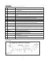
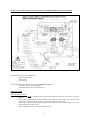
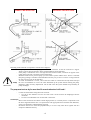
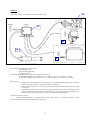
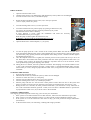
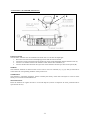
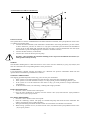
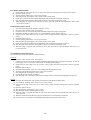
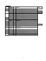
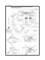
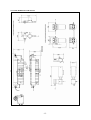
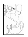
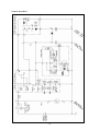
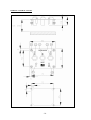
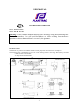
USER MANUAL
EN
LOW PRESSURE WATERMAKER
53421 : 15 l/H – 12 Volts
53422 : 30 L/H – 12 Volts
Warning : Please read this manual carefully before installing, using and maintaining this
Plastimo watermaker. You will avoid breakdown or failure resulting from incorrect
operation or misuse that would not be covered by the guarantee.
PRESENTATION
The Plastimo low pressure watermaker includes a 6 bar pump with reduced electric consumption.
The following power consumptions are given for a unit operating with 25°C and 35gr/l TDS (salinity) sea water:
- 7 Amps for the 15 L/H model
- 14 Amps for the 30 L/H model
-1-
COMPONENTS
The Plastimo low pressure watermaker comes as standard with :
REP. DESIGNATION
FUNCTION
EdM Thru-hull inlet fitting
This sea water intake must always be immersed. It insures continuous sea water feeding of the
units. Optional extra.
Situated close to the thru-hull inlet fitting, it is used to stop sea water feeding. Optional extra
V0
Seacock valve
A/B
1
Hoses
Sea water inlet valve
2
3
Strainer filter
Low pressure pump
4
5
6
7
20µ filter
5µ filter
Amplifier box
Bleed valve
8 & Pressure relief valve
21
10
Osmosis unit
11
12
C
R
E
D
Ech
Feed the unit through filters (4)&(5)
The manual 3-way inlet valve feeds the unit either with sea water in normal operating conditions or
with the water or the chimical solution from a watertank when rinsing, cleaning or storing the
diaphragms.
Is a fine screen filter that prevents coarse particles in, so to protect the low pressure pump (BP)
Driven by the electric motor; the pump rises sea water pressure to the required value between 6
and 9 bars. It must be installed under the waterline of the boat when loaded.
Filters particles up to 20 micron
Filters particles up to 5 micron (absolutely necessary before diaphragms)
It rises sea water pressure to produce fresh water through reverse osmosis diaphragm.
Bleeds the air out of the system before initial use or after having changed filters. It is also used to
run the system at low pressure during rinsing, storing or maintening operations.
This valve is used to adjust pressure if it exceeds 12 and 60 bar.
Composed of a pressure resistant pipe including the diaphragm in which sea water is de-salinated.
Cleaning outlet valve
To operate in close circuit through an auxiliary watertank with maintenance fluid : turn this 3-way
outlet valve on the oposite side from the reject position and turn the inlet valve (1) to rinsing
position.
Reject/Production outlet Manual 3-way valve that routes fresh water produced to the watertank (hose F) if salinity is correct
valve
or either reject it to the sea (through hose C).
Reject hose
Catches concentrated brine to discharge it to the sea.
Thru-hull outlet fitting
Fitted above the waterline, it ensures the reject of the brine to the sea. Optional extra (avoid
installing this fitting before or near the inlet valve)
Rinsing hose
Feeds the unit with the water or the chemical fluids from the auxiliary watertank, for rinsing or
cleaning diaphragms.
Cleaning hose
Drives the discharge water from the unit into the auxiliary watertank by switching the cleaning outlet
(11), to clean the diaphragm in closed circuit..
Sampling valve
Used to sample some fresh water production for quality control.
(see Basic mounting diagram next page)
FLOW CHART
-2-
BASIC LAYOUT DIAGRAM : INSTALLATION ON BORD WITHOUT OPTIONAL EXTRA
The watermaker comes as standard with :
- Remote control panel
- Junction box
- Filter housing
You can add to the basic system the following optional accessories :
- Automatic saltmeter (optional extra)
- Automatic flushing device (optional extra)
INSTALLATION
Mounting of the LP pump
- The LP pump must be installed at more than 200 mm under the waterline of the boat to avoid airbinding.
- The seawater intake must be situated under the pump. The hose which connects the strainer to the
pump must not form an elbow. An elbow could trap air and run dry the pump.
- We strongly recommend to installing a seacock valve (V0) before the sea water inlet valve (1) for a
total watertighness of the system.
- Power supply with cables 2x4 mm² minimum section
-3-
CORRECT INSTALLATIONS
INCORRECT INSTALLATIONS
Mounting of the elements in compliance with the above diagram :
- The pump is mounted on damping pads that absorb vibrations. It must be secured on a support
which is part of the boat structure. Same recommendations for the amplifier.
- If the pump is installed too far or too high from the seawater intake, cavitation can appear in the
pump which will rattle. Cavitation can block the pump.
- With this model of low pressure pump you can't run the system without water. Thus it is essential
that pump priming is automatic and unattended. The only way to do so is to have a rising line from
the seacock valve (V0) to the 20µ filter.
- To check if installation is correct, remove the hose which is connected to the 20µ filter and open
the valve. If installation is correct sea water should fill up the system without starting the pump.
Otherwise, make necessary adjustments. The air that enters the system should escape naturally as
IMPORTANT
pump discharges.
The pump must not run dry for more than 30 seconds otherwise it will break !
-
Connect all the elements using the hoses enclosed :
o Use the 8 mm diameter hose for the fresh water circuit between the diaphragm and the
watertank.
o Use the 15 mm diameter hose for the other connections.
WARNING :
- Most of the connections are effective under high pressure (6 or 60 bar), thus it is important to use
the hoses supplied with the unit or to replace them with appropriate hoses with the same diameters,
as they are designed to withstand these pressures.
- Each hose must be cut clean and perpendicularly to its axis. They must all be tighten with two
clamps for additional security.
-4-
WIRING
A
- For power supply use a cable 2x4 mm² minimum section.
C
D
B
E
Basic electrical installation is composed of :
- A control panel (A)
- A low pressure pump (B)
- A junction box (C)
The following options can be easily connected and are pre-wired.
- An automatic saltmeter (D), connect wires : (2 : blue), (5 : grey), (6 : brown), (7 : black)
- An automatic flushing (E), connect wires : (2 : blue), (04 : grey), (10 : brown), (12 : black)
Basic wiring :
1.
2.
3.
Connect the control panel (A) to the junction box (C) with the supplied 10x0,34 mm² cable (7m
length). For easier connection, follow the number code system .
Connect the junction box (C) to the low pressure pump (B) with the supplied 2x4 mm² cable
(2m length).
Connect the junction box (C) to the power supply terminals with a cable minimum 2x4 mm²
section if length does not exceed 10m. Otherwise use a 6 mm² cable (cable not supplied). It is
not necessary to fit a switch or a fuse as they are integrated in the installation.
Optional accessories wiring :
- Each optional instrument is supplied with a 5x0,75 mm² cable. To connect the accessory to the
junction box follow carefully the numbering on each cable.
-5-
FIRST STARTUP
1.
2.
3.
Open the inlet and outlet valves.
Check that the strainer is not damaged (2) and that the 20 µ and 5 µ filters are not damaged.
Turn the sea water inlet valve (1) towards the pump.
4.
Rotate the Reject/Production outlet valve (12) to the reject position.
(valve in reject position See photo)
5.
Turn the cleaning outlet valve (11) to the reject hose.
6.
You must first drain the low pressure pump by opening its bleed valve (22),
21
(See photo), the seawater must flow out freely without any air pocket.
Check that the strainer filter is filled up.
If water draining is erratic check the installation and make the necessary adjusmentsre
recommendations (see previous page).
When the pump is filled, tighten the bleed valve (22).
22
WARNING : Do not touch the pump adjusting screw (21)
7.
Open the bleed valve of the multiplier (7). (See photo)
12
7
8.
To start the pump press the « ON » switch on the control pannel. Make sure that the seawater flows
freely through the different parts of the system and that there is a seawater flow at the reject hose level
(R). Allow the pump, primary filtration and amplifier drain during at least 5 minutes and then tighten
the amplifier bleed valve (7).
9. Once the amplifier bleed valve is tighten, the seawater pressure in the system will rise up to 40 to 50
bar. Then after a few minutes fresh water production will start. If the reject/production outlet valve (12)
is turned to reject position, all fresh water produced is rejected to the sea. You can however see the
water produced by opening the sampling valve (ECH).
10. During the first 5 minutes, the water produced is brackish. The sampling valve (ECH) enables to taste
or test it with a automatic saltmeter (optional : 53428). Water is considered drinkable under 750 ppm.
When salinity is correct, change reject/production outlet valve (V12) position to route fresh water to the
watertank.
STARTING THE SYSTEM
1. Open the inlet and outlet valves.
2. Check that the strainer (2) and the 20 µ and 5 µ filters are not damaged.
3. Turn the sea water inlet valve (1) to the pump.
4. Turn the reject/production outlet valve (12) to reject position.
5. Turn the cleaning outlet valve (11) to the Reject position.
6. Start the pump with the "on" switch on the control pannel. If water does not flow in the system and
there is not brine rejection to the sea, drain the system again as explained in the "first start up " part.
7. During the first 2 or 3 minutes, the water produced is brackish : you must throw it away. Then taste or
test it with a automatic saltmeter (optional : 53428) to be sure that it is drinkable before to position the
reject/production outlet valve (12) to divert water to the watertank.
STOPPING THE SYSTEM
The stopping procedure depends on how long you won't use your watermaker.
1. If the system is to be left unused for for less than 48 hours, follow the basic maintenance procedure.
2. If the system is to be left unused for a 2 days to 15 days period, perform a flushing operation cycle.
3. If the system is to be left unused for more than 15 days, you must perform a storage maintenance
(sterilization).
4. At the end of the season, for winterising : flushing and storage procedure.
-6-
BASIC MAINTENANCE PROCEDURE
1. Press the « OFF » switch on the control pannel.
2. Once the water production is stopped, close the seacock valve (V0) and turn the reject/production outlet
valve (12) to reject position.
FLUSHING PROCEDURE
1. Press the "OFF" switch on the control pannel.
2. Collect 10 litres of water from the main watertank and put them in the rinsing tank. Warning : do not
use dock supply water as it contains chlorine that can damage the diaphragm.
3. Position the sea water inlet valve (1) in order that water is driven from the rinsing tank and to the low
pressure pump.
4. Open the bleed valve (7).
5. Let the cleaning outlet valve (11) in reject position.
6. Start the pump by pressing the "ON" switch on the control panel. Check the water level in the tank.
7. Fresh water removes the salt from the diaphragm and avoid the development of bacteria.
8. Stop the pump before the rinsing tank is empty to avoid air entering the circuit.
9. After the pump is stopped, close the seacock valve (V0) and turn the reject/production outlet valve (12)
to reject position.
STORAGE PROCEDURE
1. You need the Storage fluid (Plastimo reference 53427)
2. Follow the flushing procedure from (1) to (9) and add the storage fluid at stage (2).
WINTERISING PROCEDURE
1. You need the winterising kit (Plastimo reference53424 : it includes a cleaning fluid, a storage fluid, 5 µ
and 20 µ filters).
2. Rinse first the diaphragm with fresh water (stage 1 to 8 of the flushing procedure).
3. Fill again the rinsing tank with 10 litres of fresh water and mix the cleaning fluid.
4. Let the the sea water inlet valve (1) in pumping position, from the watertank through (E)
5. Keep the bleed valve (7) opened to avoid pressure rise in the diaphragm.
6. Turn the cleaning outlet valve (11) to the rinsing tank through the hose (D) and get a closed circuit.
7. By pressing the « ON » switch start the pump and let it run 10 minutes for a cleaning cycle.
8. After 10 minutes, flush out the cleaning solution and perform the diaphragm rinsing cycle with fresh
water and then a storage maintenance procedure (see storage procedure).
9. Whatever the status of the filters (4) and (5) replace them to avoid build up of bacteria.
10. It's necessary to have water left in the diaphragm and make sure that it can't freeze.
-7-
AUTOMATIC SALTMETER (OPTIONAL)
A
P
B
INSTALLATION
The automatic saltmeter must be installed in the fresh water circuit after the diaphragm.
1. Disconnect the hose between the diaphragm outlet and the main watertank.
2. Connect the 8 mm ∅ hose between the fresh water outlet of the diaphragm and the saltmeter inlet. (P).
3. Connect a second hose between the saltmeter outlet and the main watertank (A).
4. Connect the third hose between the reject hose of the saltmeter and the reject hose of the system (B).
WIRING
The automatic saltmeter is delivered with 4 wires. The 4 wires are numered (2-), (5), (6) and (7) and must be
connected to the corresponding numbers of the junction box..
OPERATION
The saltmeter is completely automatic, checks constantly the salinity of the water and rejects it to the sea if the
salinity level exceeds recommended level.
MAINTENANCE
Rinse the saltmeter at regular intervals to avoid salt deposits (if there are deposits all water produced will be
rejected into the sea).
-8-
AUTOMATIC FLUSHING (OPTIONAL)
A
B
C
INSTALLATION
This optional device must be installed between the main freshwater watertank, the reject/production outlet valve
(1) and the low pressure pump.
1. Connect the main watertank (if the watertank is situated above the rinsing instrument, you can connect
it direct. Otherwise, you have to connect it to a by-pass of the under pressure fresh water distribution
circuit) to the A inlet fitted with activated charcoal. This filter is used to dischlorinate the water from
the watertank to protect the diaphragm (few resistant to available chlorine).
2. Connect the filter outlet (2) to the B inlet.
3. Connect the C outlet to the low pressure pump.
Warning : when installing the automatic flushing kit do respect the installation instructions (see
Main §) and avoid any air trap.
WARNING
WIRING
The automatic flushing device is delivered with a 4 wires. The 4 wires are numered (2-), (04), (10) and (12) and
must be connected to the corresponding numbers of the junction box..
OPERATIION
It was designed to simplify stopping procedures. For a Plastimo low pressure watermaker fitted with this
optional device maintenance procedures are as follows :
STOPPING THE SYSTEM
The stopping procedure depends on how long you won't use your watermaker.
1. If the system is to be left unused for less than 48 hours, follow the basic maintenance procedure.
2. If the system is to be left unused for a 2 days to 15 days period, perform a flushing operation cycle.
3. If the system is to be left unused for more than 15 days, you must perform a storage maintenance
(sterilization).
4. At the end of the season, for winterising : flushing and storage procedure.
BASIC MAINTENANCE
1. Press the « OFF » switch on the control panel.
2. Once the water production is stopped, close the seacock valve (V0) and rotate the reject/production
outlet valve (12) to reject position.
FLUSHING PROCEDURE
1. Press the « OFF » button on the control panel.
2. Press the « Flushing » button. The pump is activated and pump water from the main watertank. The
change of supplying source is fully automatic.
3. This optional rinsing instrument includes a timer for an automatic cut off after a few minutes.
4. When rinsing operation is over, close the seacock valve (V0) and turn the reject/production outlet valve
(12) to reject position.
-9-
FLUSHING PROCEDURE
1. Position the sea water inlet valve (1) to drive water from the rinsing tank to the low pressure pump.
2. Open the bleed valve (7).
3. Put the cleaning outlet valve (11) in reject position.
4. Start the pump by pressing the "ON" switch on the control panel.
5. Fresh water removes the salt from the diaphragm and avoid the development of bacteria.
6. Stop the pump before than the rinsing tank is empty to avoid air entering the circuit.
7. After the pump is stopped, close the seacock valve (V0) and rotate the reject/production outlet valve
(12) to reject position.
STORAGE MAINTENANCE
1. You need the Storage fluid (Plastimo reference 53427)
2. Press the "OFF" switch on the control panel.
3. Collect 10 litres of water from the main watertank and put them in the rinsing tank.
4. Follow the flushing procedure from (1) to (9) and add the storage fluid at stage (2).
5. Position the sea water inlet valve (1) in order to drive water from the rinsing tank to the low pressure
pump.
6. Open the drain screw (7).
7. Let the cleaning outlet valve (11) in reject position.
8. Start the pump by pressing the "ON" switch on the control panel.
9. Fresh water removes the salt from the diaphragm and avoid the development of bacteria.
10. Stop the pump before than the rinsing tank is empty to avoid air entering the circuit.
11. After the pump is stopped, close the seacock valve (V0) and rotate the reject/production inlet valve (12)
to reject position.
WINTERISING MAINTENANCE
You need the winterising kit (Plastimo reference53424).
Cleaning
1. Press the "OFF" switch on the control panel.
2. Collect 10 litres of water from the main watertank and put them in the rinsing tank. Warning : do not use
dock supply water as it contains chlorine that can damage the diaphragm.
3. Position the sea water inlet valve (1) in order to drive water from the rinsing tank to the low pressure
pump.
4. Open the drain screw (7).
5. Turn the cleaning outlet valve (11) to the rinsing tank through the hose (D)
6. Turn the reject/production outlet valve (12) to reject position.
7. Start the pump by pressing the « ON » switch
8. Let the fluid act for at least 10 minutes
9. Stop the pump after 10 minutes, flush out the cleaning solution and start the diaphragm rinsing cycle
Storage
10. Fill again the rinsing tank with 10 litres of fresh water and add the cleaning fluid.
11. Check that the cleaning outlet valve (11) is in reject position.
12. Position the sea water inlet valve (1) in order to drive water from the rinsing tank to the low pressure
pump.
Open the drain screw (7).
Start the pump by pressing the « ON » switch
Stop the pump before the rinsing tank is empty
After the pump is stopped, close the seacock valve (V0) and turn the reject/production inlet valve (2) to
reject position.
17. Whatever the status of the filters (4) and (5) replace them to avoid build up of bacteria.
18. It's necessary to have water left in the diaphragm and make sure that it can't freeze.
13.
14.
15.
16.
-10-
SPARE PARTS
Part number
Ind
SLCE
1 & 11 711047
2
710014
651001
3
656200
653001
711002-02
711101
4
711058
5
711014
6
103121-40
7
609046
600045
8 & 21
6-66.105
10
711205
12
719251
36
724036
40
722072
42
725090
APM50
IPR3FAD2
APM51 & 52
IPR5FAD2
53
OR-233358
54
OR-233359
55
OR-233358
56
OR-233356
880010
880030
N°
Description
Model
MANUAL VALVE 3 X F 1/2" RX
STRAINER FILTER PLAST MM1/2"
LP PUMP 150L ETW30
DC MOTOR 12V 125W 1650T
320 liters LP PUMP ETW30
O RING FILTER FATA 10"
FILTER 7" DUPLEX ATLAS
CARTRIDGE 7"- 20 MICRON
CARTRIDGE 7"- 5 MICRON
S/E ETW PLAST RECUPERATOR
BLEED VALVE AQ-B ETW
Ø8 NEEDLE
SPRING ETW
DIAPHRAGM 4"-21 SW
BRASS 3-WAY VALVE 3xF 1/4
2.5A FUSE
20A UNI 3130 DC CIRCUIT BRAKER
RELAY 1RT 30A 12VCC
PUSH BUTTON
PUSH BUTTON
LED INDICATOR D3 GREEN 12VCC
LED INDICATOR D3 YELLOW 12VCC
LED INDICATOR D3 GREEN 12VCC
LED INDICATOR D3 RED 12VCC
CONTROL PANNEL ETW PLAST 12 VCC
JUNCTION BOX PLAST
-11-
15L/H
15/30L/H
30L/H
15/30L/H
BASIC DIAGRAM
-12-
OUTLINE DIMENSION DRAWING
-13-
WIRING DIAGRAM
-14-
WIRING DIAGRAM
-15-
REMOTE CONTROL PANNEL
-16-