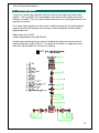
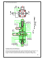
1
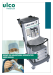
ELITE 615
ANAESTHETIC MACHINE
Ulco Medical
25 Sloane St
Marrickville NSW 2204
USER MANUAL
ii
Copyright © 2005 by Ulco Medical
All rights reserved.
No part of this publication may be reproduced in any form, in an electronic retrieval system
or otherwise, without the written permission of the Ulco Medical.
All Ulco products are subject to a program of continuous development and the
manufacturer reserves the right to make alterations in design and equipment without prior
notice.
Document Number: EL6-UM-001
Version: 1.0
Table of Contents
1 Introduction .......................................................................................... 4
1.1
Restriction ......................................................................................................4
2 Specifications ....................................................................................... 5
3 Warranty................................................................................................ 7
4 Protocol for checking the Anaesthetic Machine ................................ 8
5 Anaesthesia Equiptment Check-out Procedure............................... 13
5.1
Scan the Machine ........................................................................................13
6 Preparation for Use ............................................................................ 17
6.1
Cylinder fitting ( Pin Index ) ..........................................................................17
6.2
Pipeline Hoses .............................................................................................17
6.3
Testing .........................................................................................................17
7 Test Procedure ................................................................................... 19
7.1
Gas supply circuit test ..................................................................................19
7.1.1
Oxygen circuit (cylinder)....................................................................19
7.1.2
Oxygen circuit pipeline ( Fitted as standard) .....................................19
7.1.3
Nitrous oxide (cylinder)......................................................................19
7.1.4
Nitrous oxide circuit pipeline (Fitted as standard)..............................19
7.2
Flowmeters ..................................................................................................19
7.3
System .........................................................................................................20
7.4
Emergency Oxygen Flush............................................................................20
7.5
Oxygen Warning Device ..............................................................................20
7.6
Anti-Hypoxic Device.....................................................................................21
8 Routine Care ....................................................................................... 22
8.1
Cylinder flow control valves..........................................................................22
8.2
Cleaning.......................................................................................................22
8.2.1
8.3
DO NOT AUTOCLAVE......................................................................22
Pipe line hose assemblies............................................................................22
9 Major Components of the Machine ................................................... 23
ii
Elite 615 Anaesthetic Machine
9.1
Patient Block ................................................................................................23
9.2
Main regulators ............................................................................................25
9.2.1
Servicing the regulator ......................................................................25
9.3
Second stage regulators ..............................................................................27
9.4
Oxygen failure warning device .....................................................................28
9.5
Anti Hypoxic Device .....................................................................................32
9.6
Flowmeters ..................................................................................................35
10 Additional components of the machine............................................ 37
10.1 Gas Controls ................................................................................................37
10.2 Vaporisers....................................................................................................37
10.3 Ventilator......................................................................................................37
10.4 Soda-lime absorber......................................................................................38
10.5 The anti-hypoxic device ...............................................................................38
10.6 Gas Manifold................................................................................................39
10.7 Pressure gauges..........................................................................................39
10.8 Scavenging ..................................................................................................39
10.9 Auxiliary oxygen outlet .................................................................................39
10.10 Pipeline hose assemblies ............................................................................39
10.11 Patient circuitry ............................................................................................40
10.11.1 The Circle Circuit ...........................................................................40
10.12 Other accessories ........................................................................................40
10.12.1 Accessory power ...........................................................................41
11 Repair and Service ............................................................................. 41
11.1 Service intervals and service components for Elite ‘615’ .............................41
12 Terms and conditions ................................................................... 12-42
3
Elite 615 Anaesthetic Machine
Elite 615 and Compact Anaesthetic Machines.
The Elite ‘615’ Anaesthetic Apparatus can be easily upgraded from its basic configuration
with optional accessories and attachments including full range of patient monitors to
provide a comprehensive Anaesthesia workstation.
The compact Anaesthetic Machine can also be upgraded from its basic form to include a
range of optional accessories and attachments.
This manual provides information for preparation, assembly and maintenance of the ‘Elite
615 also allied equipment in the ULCO range of anaesthesia apparatus. Although this
equipment has been carefully designed for simplicity of assembly and use, it is
recommended that the contents of this manual be studied before attempting preparation or
maintenance of the equipment.
ULCO or its agents provide a comprehensive service and it is recommended that
advantage of this be taken for the safe and reliable upkeep of this equipment. Customers
requiring this service or advice with operating problems should contact ULCO or its
accredited agents.
If equipment is to be attached to the ULCO range of Anaesthesia machines which has not
been specifically designed, or supplied by ULCO, it is recommended that customers
consult ULCO as to the suitability of the equipment and necessary modifications to the
apparatus.
WARNING
NO OIL OR GREASE OF ANY KIND
MUST BE ALLOWED TO COME
INTO CONTACT WITH HIGH
PRESSURE OXYGEN
IN THE USA THIS DEVICE IS RESTRICTED TO SALE BY, OR ON THE ORDER OF, A
PHYSICIAN.
4
Elite 615 Anaesthetic Machine
Elite ‘615’ Anaesthesia Machine
A special version is available for use in MRI units.
HEIGHT
1370mm
WIDTH
720mm
DEPTH
690mm
WEIGHT
70Kgs. Not including Vaporiser or Absorber.
Standard items supplied with Elite ‘615’
GAS CIRCUITS
Pipeline Oxygen & Nitrous oxide (400kPa)
And Air With gauges.
BACKBAR ASSEMBLY
All Back Bar components fitted with
23mm connectors.
FLOWMETER
3 Gas (Oxygen, Nitrous Oxide & Air)
VAPORISER MOUNTS
Selectatec type x 2
COMMON GAS OUTLET
Emergency Oxygen flush
Patient safety valve
Male connector
Block with
45 L/Min. flow
50 Cm/H2O
22/15 mm
OXYGEN FAILURE
Warning device with audio visual warnings
DRAWER UNITS
1 x Large drawer 150mm deep & 1 x small
Drawer 100mm deep.
OPTIONAL ITEMS
ADDITIONAL DRAWERS
Maximum 2 small drawers. Total of four.
VAPORISERS
Halothane, Ethrane & Isoflurane
(Selectatec Type)
5 GAS FLOWMETER
With Air flowmeter tube.
5
Elite 615 Anaesthetic Machine
ANTI HYPOXIC DEVICE
Prevents delivery of hypoxic mixtures,
Maintains 25% O2 flow.
M.C.S. VALVE
ADE switch selects Bain or Lack
Configuration.
PAEDIATRIC CIRCUIT
Jackson Rees system
MAGILL CIRCUIT
For spontaneous breathing anaesthesia
BAIN ADAPTOR
For controlled breathing anaesthesia
BAIN CIRCUITS
Co Axial circuits for use with Bain
Adaptor
CO2 ABSORBER
1 or 2 kg. capacity
6
Elite 615 Anaesthetic Machine
All Ulco products are guaranteed to be free of defects of workmanship or material for a
period of one year from the date of delivery. The following are exceptions to this warranty:
1.
Defects caused by misuse, mishandling, tampering, or by modifications not
authorised by Ulco or its appointed agents and are not covered.
2.
Rubber and plastic components and materials are warranted to be free of defects
at the time of delivery.
3.
Respiratory volume sensors, fuel cells oxygen sensors have a six month limited
warranty. Fuel cell oxygen sensor capsules have a warranty from date of delivery
of eight months.
4.
Warranty for Durasensors*, is limited to a period of six months from the date of
delivery. Oxisensors TM are warranted to be free of defects at time of delivery.
Any product which proves to be defective in workmanship or material will be replaced,
credited or repaired with Ulco holding the option. Ulco is not responsible for deterioration,
wear or abuse. In any case, Ulco will not be liable beyond the original selling price.
Goods are subject to the terms of applicable warranty. Defective products will be
accepted for return at Ulco’s discretion, and only during the warranty period. Application of
this warranty is subject to the following conditions:
1.
Ulco or its authorised agents must be promptly notified, in writing upon detection of
the defective material or equipment.
2.
Defective material or equipment must be returned, shipping prepaid, to Ulco or its
authorised agent.
3.
Examination by Ulco or its authorised agent must confirm that the defect is in fact
covered by the terms of this warranty.
4.
Notification in writing, of defective material or equipment must be received by Ulco
or its agent no later than two (2) weeks following expiration of this warranty.
In order to assume complete protection under this warranty, the warranty registration card,
and or periodic manufacturer’s service record (if applicable) must be returned to Ulco
within 2 weeks of receipt of the equipment.
The above is the sole warranty provided by Ulco. No other warranty expressed or implied
is intended. Representatives or agents of Ulco are not authorised to modify or amend the
terms and conditions of this warranty.
*DURASENSORS and OXISENSORS are Trademarks of Nellcor Incorporated.
7
Elite 615 Anaesthetic Machine
This is one of the College Policy Documents of the Australian and New Zealand College of
Anaesthetists. The College Policy Documents set down the formal, council-approved
guidelines for practice in a wide range of circumstances.
Hospitals require these documents to be readily accessible to relevant staff at all times for
reference as required. The Policy Documents are also referred to by Government and
other bodies, especially in the process of accreditation of health care facilities.
The College Policy Document ‘Protocol for checking the Anaesthetic Machine’ reads as
follows:
1
Introduction
1.1 The regulated supply of gases and vapours for anaesthesia and the provision of
controlled ventilation for the patient are the main functions of the anaesthetic
machine or workstation. Because oxygenation and ventilation are essential for every
patient and because even a brief failure to maintain them may cause irreparable
harm, every machine must be regularly and thoroughly checked to ensure that all
functions are correctly maintained.
1.2 There must be a reserve facility to maintain oxygenation and ventilation of a patient
should failure of the primary systems occur.
1.3 To ensure early detection of any failure in the anaesthetic machine, it is essential that
appropriate alarms are present in the machine and that there is monitoring of the
state of the patient as specified in College Policy Document P18 Monitoring During
Anaesthesia.
1.4 This protocol incorporates three components:
1.4.1
Level One check. This is very detailed and is required a) on any new
machine and b) on all machines after the required regular servicing. This
check will usually be performed by the service person – whether from the
equipment provider, or from the Bio Engineering Department.
1.4.2
Level Two check. This should be performed at the start of each anaesthetic
session.
1.4.3
Level Three check. This should be performed immediately before
commencing each
subsequent anaesthetic.
responsible for
Each check must be derived specifically for the machine under test and the
Anaesthesia Department ( on behalf of the hospital administration) is
The training and accreditation of the personnel involved with each test.
1.5 Accreditation for checking the anaesthetic machine requires:
8
Elite 615 Anaesthetic Machine
2
1.5.1
Level One. Attendance at a manufacturer’s course or a programme
developed by the hospital’s Anaesthesia Department in consultation with a
qualified Biomedical Engineer.
1.5.2
Levels Two and Three. Checks must follow protocols specifically developed
for the machine under test. All personnel must be trained in correct
procedures and accredited to perform them by the Anaesthesia Department.
The specific protocols should be attached to the machine.
Protocols
2.1 Level One check. This must be performed by on anaesthesia machines a) before
they enter service and b) following all service inspections, which must be performed
at regular and specified intervals.
2.1.1
The Hospital, Anaesthesia Department or body responsible for the equipment
shall keep a detailed record of the equipment and the checking procedures.
This process requires that a checklist be maintained. The checklist will be
based on manufacturer’s recommendations. The protocols shall describe
checking and calibration protocols and the intervals at which these must be
performed.
2.1.2
The anaesthetic machine must have a prominent label to advise of past
service(s) and to indicate when the next check is due. This label must be
visible to the anaesthetist.
2.1.3
Gas Delivery System. The check shall include:
2.1.3.1 Quantifying and minimising leaks
2.1.3.2 Excluding crossed pipelines within the machine
2.1.3.3 Ascertaining the correct functioning of non-return valves throughout the
system
2.1.3.4 Ascertaining the integrity of oxygen failure prevention and warning
devices
2.2
2.1.4
Anaesthetic Vapour Delivery System. The check shall include the accuracy
of vapour output and delivery devices.
2.1.5
It is essential to ascertain that the machine as supplied complies with the
relevant Australian or New Zealand standard.
2.1.6
The check specified above must be undertaken by a suitably qualified
person, usually the service provider. The check must be recorded with
inclusion of information as to what was checked, and by whom. After
servicing, the particular checklist will relate to the actual service performed.
Level Two check. This check must be undertaken by a suitably qualified person
(such as an
anaesthetist, technician or nurse) in accordance with a
protocol specific for the particular machine. Thus several different protocols may be
required in a single hospital. These will serve to verify the correct functioning of the
9
Elite 615 Anaesthetic Machine
anaesthesia machine before it is used for patient care. Equipment required for the
tests must be available on each machine.
`
2.2.1 High Pressure System.
2.2.1.1 Check oxygen cylinder supply. Ensure that cylinder content is sufficient
for its intended purpose.
2.2.1.2 Check that piped gas supplies (where present) are at the specified
pressures and that following high pressure system checks, the
cylinders are turned off.
2.2.1.3 Confirm correct pipeline supply by using an oxygen analyser or multigas
analyser distal to the common gas outlet.
2.1.2
Low Pressure System.
2.2.2.1Check control valves and flow meters. Turn on each gas and observe
the appropriate operation of the corresponding flow meter. Check the
functioning of any interactive anti-hypoxic device
2.2.2.2.Check that any required vapouriser is present:
2.2.2.2.1
Check that adequate anaesthetic liquid is present.
2.2.2.2.2
Ensure that the vapouriser filling ports are closed.
2.2.2.2.3
Check correct seating and locking of a detachable vapouriser.
2.2.2.2.4
positions.
Test for circuit leaks for each vapouriser in both on and off
2.2.2.2.5
Ensure power is available for electrically operated vapourisers.
2.2.2.3 Check for pre-circuit leaks using a method sensitive to 100mL/minute
and appropriate for specific machine.
2.2.2.4 Breathing systems. Check the general status to ensure correct
assembly and absence of leaks. The precise protocol will depend on
the anaesthesia circuit to be used.
2.2.2.4.1 Perform leak test on the breathing system by occluding the
patient connection, applying a fresh gas flow of 300mL/min and
ensuring that a pressure of greater than 30cm H2O is sustained.
2.2.2.4.2 In the circle system check its integrity and the functioning of
unidirectional valves. This can be accomplished with a breathing
bag on the patient limb of the Y-piece. Ventilate the system
manually using an appropriate fresh gas flow. Observe inflation
and deflation of the attached breathing bag and check for normal
system resistance and compliance. Observe movement of
unidirectional valves. Check function of adjustable pressure
10
Elite 615 Anaesthetic Machine
limiting (APL) valve by ensuring easy gas spill through APL when
the two breathing bags are squeezed.
2.2.3
Automatic Ventilation System. This should be checked according to the
manufacturer’s recommendations. This test protocol must be present on
the machine. A test lung (such as a suitably compliant bag) may be used to
check the function of the ventilator. Where practicable, gas flow should be
reduced to check for leaks. The functioning of disconnection and high
pressure alarms should be checked at this time.
2.2.4
Scavenging System. This should be checked after connection to APL valve
and ensuring a free gas flow. If there is negative pressure in any part of the
system, ensure that this does not lead to emptying of the breathing system.
With the patient occluded, a full breathing system should not empty with the
APL valve open.
2.2.5
Emergency Ventilation System. Verify the presence and functioning of an
alternative method of providing oxygen and of controlled ventilation (such as
self-inflating bag).
2.2.6
Other apparatus to be used. This should be checked according to specified
protocols. Attention should be given to:
2.2.6.1 Equipment used for airway maintenance and intubation of the
trachea.
2.2.6.2 Suction apparatus.
2.2.6.3 Gas analysis devices.
2.2.6.4 Monitoring equipment. Special attention should be paid to alarm
limits and any necessary calibration.
2.2.6.5 Intravenous infusion devices.
2.2.6.6 Devices to reduce hypothermia during anaesthesia.
2.2.6.7 Breathing circuit humidifiers.
2.2.6.8 Breathing circuit filters.
2.2.7Final check. Ensure vaporisers are turned off and that the breathing system is
purged with air or oxygen as appropriate.
2.3
Level three check. Immediately before commencement of each anaesthetic, the
anaesthetist should:
2.3.1 Check a changed vaporiser using the protocol outlined in 2.2.2.2.
2.3.2 Check a changed breathing circuit using the protocol outlined in 2.2.2.4.
2.3.3 Check that equipment as specified in 2.2.6 is ready for the next case.
11
Elite 615 Anaesthetic Machine
This policy document has been prepared having regard to general circumstances, and it is
the responsibility of the practitioner to have express regard to the particular circumstances
of each case, and the application of this policy document in each case.
Policy documents are reviewed from time to time, and it is the responsibility of he
practitioner to ensure that the practitioner has obtained the current version. Policy
documents have been prepared having regard to the information available at the time of
their preparation, and the practitioner
Should, therefore have regard to any information, research or material which may have
been published or become available subsequently.
Whilst the College endeavours to ensure that policy documents are as current as possible
at the time of their preparation, it takes no responsibility for matters arising from changed
circumstances or information or material, which may have become available subsequently.
Promulgated: 1984
Reviewed: 1990, 1996
Date of current document: Oct 1997
© This document is copyright and cannot be reproduced in whole or in part without prior
permission.
12
Elite 615 Anaesthetic Machine
!"
#
$
%
The procedure described below is one method of checking out the Anaesthesia machine
that will detect almost any serious problem. (Special procedures may be required if the
machine has been modified or has special medical equipment attached to it.)
The complete check-out procedure or its equivalent should be performed prior to the first
time a machine is used each day. The main checks should also be carried out before
each use of a machine on a different patient.
Ensure that an anaesthetic machine checklist is completed as the procedure is carried out,
with all details submitted.
Comprehensive pre-use and or daily inspection procedure is a vital component of a
complete anaesthesia patient safety program. It must not, however, be relied upon to
prevent all equipment related complications. Some types of failures may not be detected
without an exhaustive inspection protocol, and some equipment failures will inevitably
occur during use.
There is no substitute for the continuous presence, vigilance and good judgement of a
trained anaesthetist during anaesthesia and mechanical ventilation.
Before starting, be sure to have all necessary equipment
Start by verifying that the items necessary for the procedure are present. Appropriate
EMERGENCY drugs and equipment should be close at hand. Be sure to check
Laryngoscopes, as they are the equipment items that fail most frequently.
Visually examine the anaesthesia machine to identify obvious problems, such as broken
flowmeter tubes or missing probes and breathing circuit connectors. Identify and log the
machine serial number on the anaesthetic record as this may be needed if a problem were
to be suspected.
*PROCEDURE
1. Turn on the monitoring equipment, and allow time to stabilize before calibrating. (O2
Analyser)
2. Connect Scavenging System. (All fittings should be sequential to prevent
misconnection). Activate the system prior to carrying out any procedure or check to
avoid polluting the Operating Room.
3. Check back bar integrity and selectatec type mounts. Clear all obstructions such as
tubes and lines which could prevent correct Vaporiser mounting.
4. Various methods of mounting Vaporiser are currently used such as the OFF LINE or
FIXED but the most common is the SELECTATEC type mounting system in which a
mounting block is permanently attached to the back bar, and the Vaporiser is locked on
by means of DZUS (Aircraft type) quick release fastener. Gas flow is diverted through
the Vaporiser via the ports when the Vaporiser is placed on the mounting block. The
selectatec system allows for interchangeability of Vaporiser(s), either for the use of an
13
Elite 615 Anaesthetic Machine
alternative volatile agent, or for the maintenance and servicing, as well as rendering the
Machine “Vapour Free” if necessary. As the
Seal between the Vaporiser and the Selectatec mounting block is dependent on an
“O” ring retained at the bottom of each of the valve stems, it is important that they be
examined each time the Vaporiser is removed from the Anaesthesia Machine.
IMPORTANT….. Make sure that only one “O” ring is on each of the mounting’s valve
stems.
It is recommended that spare “O” rings be kept with each Machine.
Vaporisers not attached to the Anaesthesia Machine must be prevented from tipping
over, storage racks are available to store unused Vaporisers. Vaporisers should be
emptied prior to being moved.
NB. Please read separate instruction manual issued with each Vaporiser prior to use.
14
Elite 615 Anaesthetic Machine
15
Elite 615 Anaesthetic Machine
16
Elite 615 Anaesthetic Machine
&
'
The instruction in this section only details the procedure for connecting the gas supplies.
&
$
(
)*
Optional Item on Elite ‘615’
1.
Check the cylinder for correct gas type.
2.
Check that an intact Bodok seal is fitted to the yoke.
3.
Remove the seal wrap from the cylinder valve.
4.
Open the cylinder valve momentarily to blow any foreign matter from the gas outlet.
5.
Insert the cylinder into the apparatus yoke, ensuring that the outlet orifice of the
cylinder
Valve engages with the inlet of the yoke. Tighten the yoke clamping screw.
&
+
The pipeline hoses are fitted with non interchangeable connectors (Handwheels)
suitable for
Australian wall outlets or cylinder regulators. Each type of gas hose and handwheels is
colour
Coded and diameter size indexed. Hoses should be screwed to the appropriate
connecting
Block on both the supply and the apparatus. Sufficiently tighten to provide a gas tight
seal.
&
,
The apparatus is now ready for testing prior to use. All the components and assembly are
fully tested prior to despatch from our factorybut may have loosend during transport.
Ensure that all components are secure.
1.
Fit the gas cylinders or pipeline gas supplies as detailed in Preparation for Use.
2.
Test the vaporiser, spacer cone, socket joints and safety valve for leaks by
blocking the common gas outlet. Raise the pressure in the backbar using the
oxygen flow control valve on the flowmeter until the patient safety valve pressure
is obtained. Check for leaks from the outlet back to the flowmeter (a soapy
solution can be used to test this).
3.
Turn off all gas supplies (clean all traces of soap solution, if used, from the
machine).
The main components used on Elite ‘615’.
1.
The flowmeter(s) with flow control valves if no anti hypoxic device id fitted. (If
anti-Hypoxic device is fitted the floe control valves are fitted to the Anti hypoxic
device.)
17
Elite 615 Anaesthetic Machine
2.
The vaporiser mount is a selectatec type and accepts most brands of
vaporiser.
3.
The patient block complete with emergency oxygen and patient safety blow off
valve is fitted with a non return valve to prevent back pressure to the
vaporiser(s). A 22/15mm male connector allows connection of the various
circuits or supplies gas to an absorber.
18
Elite 615 Anaesthetic Machine
- ,
-
.
Before any tests are carried out, it is important to ensure that the cylinders are not leaking
around the main valve or the Bodok seal.
-
/)
(
*
1.
Connect the cylinder to the yoke of the pin-index unit.
2.
Check that the oxygen flow control valve is closed –(do not force in any direction.)
3.
Turn cylinder ON and check contents gauge – do not use if less than half full.
4.
Turn cylinder OFF and check that the gauge does not drop more than one division in
one minute. Should the gauge drop more than one division in one minute, locate the
leak and rectify.
5.
Ensure that no leaks are present around the cylinders main valve or Bodok seal.
-
/)
(0
*
6.
Check as for item 2.
7.
Connect oxygen pipeline hose to suitable supply and to the apparatus.
8.
Check that the pressure is 400kPa.
9.
Check for leaks and rectify should they leaks exist.
-
1
) (
*
10. Connect nitrous oxide cylinder to yoke of pin index unit.
11. Check that nitrous oxide flow control valve is closed.
12. Turn on nitrous oxide cylinder and check relative gauge rise.
13. Turn off cylinder and check that the gauge pressure does not drop more than one
division in a minute. Test as in 4.
-
1
)
(
0
*
14. Check that nitrous oxide flowmeter flow control valve is closed.
15. Connect nitrous oxide pipeline hose to suitable supply and to the apparatus.
16. Check that pressure is 400kPa.
17. Test as in 13.
-
0 2#
18. According to the gases relevant to the flowmeter tube, turn on the appropriate gas
supply.
19
Elite 615 Anaesthetic Machine
19. Rotate flow control valves anti-clockwise to open and check that the bobbin or ball
rotates freely and that the rise and fall of the bobbin or ball is free relative to the
valve position.
20. Close the flow control valve and ensure that the bobbin or ball returns to the base of
the flowmeter tube.
21. Repeat this procedure for each gas, turning off each gas supply after use.
NOTE Use the oxygen analyser to ensure that no cross connection of gases has
occurred.
-
#
•
Connect a manometer with Tee piece to the common gas outlet and occlude the other
end of the Tee with the palm of the hand.
•
Open the oxygen flow control valve carefully to 100mL. Flow is reached. The
manometer gauge should indicate at least 40cm/H2O pressure, if this pressure cannot
be achieved a leak exists and should be rectified.
•
Repeat test with vaporiser fitted, and test with vaporiser in the ON and OFF positions.
WARNING
If the system is gas tight, higher pressures may be achieved and these
could damage the manometer gauge if care is not taken.
-
/)
!#
0
•
Ensure that oxygen supply is ON. Depress the flush button to check that flow exists.
•
Connect a 2 litre bag to the common gas outlet, and using a stop watch to time,
depress the flush button. Ensure that the bag fills within 3.5 seconds. This ensures
flows of 35L/min.
-
/)
34
•
Turn “ON” both the oxygen and nitrous oxide supply (use the pipeline Emergency
Oxygen Flush).
•
Set a flow of 1 litre of oxygen and a flow of 3 litres of nitrous oxide on the appropriate
flowmeters.
•
Turn OFF the oxygen supply and observe the pipeline gauge pressure of the oxygen
supply.
•
When the pipeline pressure drops to approximately 220kPa the whistle should start to
sound and shortly after the nitrous oxide flow should cut off (bobbin or ball drops to the
base of the flow tube).
•
The oxygen flow must be maintained and the whistle should sound for at least 7
seconds. It is advisable to have an oxygen analyser fitted to the common gas outlet in
order to ensure that the oxygen percentage does not drop to below 21% for the
duration of the warning.
20
Elite 615 Anaesthetic Machine
•
Reinstate oxygen supply and the nitrous oxide flow should resume and the whistle is
silenced.
•
If the test is satisfactory, turn off all flow control valves and their relative supplies.
-&
%+
) 34
•
With all gas supplies connected, attach oxygen analyser to the common gas outlet.
•
Turn ON air (if fitted) and open and close flow control valve. The air flowmeter bobbin
should rise and fall in the normal way (air is not a hypoxic gas).
•
Turn ON oxygen and nitrous oxide supplies.
•
Ensure that the oxygen flow control valve is closed and that no oxygen flow is
registering in the oxygen flowmeter tube (bobbin is at the base of the tube).
•
Open the nitrous oxide flow control valve several turns and observe the nitrous oxide
flowmeter tube. No flow should register (the device prevents flows of 100% nitrous
oxide).
•
With the nitrous oxide flow control valve left open and with NO nitrous oxide flow, open
the oxygen flow control valve until 1 litre oxygen is flowing. Note that nitrous oxide is
now flowing at around 3L/min, and the oxygen analyser is at 25% oxygen flow.
•
Gradually reduce the flow of oxygen and note that the nitrous oxide is simultaneously
reduced while the oxygen percentage remains above 21%.
NOTE The anti-hypoxic device is not a mixer - the function of the device is to prevent
inadvertant delivery of hypoxic mixtures. The oxygen percentage should be set
5% (21% to 30%). No nitrous oxide flow should be able to be set without first
setting an oxygen flow.
21
Elite 615 Anaesthetic Machine
5
$
Before connecting a cylinder of gas to the yoke assembly on an Anaesthetic Machine,
inspect the Bodok seal for wear and replace if necessary. When removing an old seal, do
not scratch the surface
of the yoke screw seating as this can cause gas leaks at high pressure. It is recommended
that the Bodok seals only are used for replacements. Cylinder valves should always be
opened partially before fitting them onto a yoke to ensure that any dust particles and other
foreign matter that can cause damage or explosion are removed.
5
$
2
44
When a cylinder has been fitted into the yoke, the cylinder valve should be turned ‘on’
gently until fully opened. Sudden high flow and rapid gas expansion create loud noise and
may also damage the contents gauge.
5
$
Avoid use of solvents and abrasive cleaning agents.
5
3/1/, ',/$6 7!
Rubber Goods
Clean and sterilise in accordance with infection control guideline and manufacturers
recommendations.
5
#8
The Pipeline hose assemblies are fitted with NON INTERCHANGEABLE connectors at
both ends of the hose. Each hose is colour coded to ISO STD for a particular gas. Each
hose must be connected to the correct gas inlet and sufficiently tighten to prevent gas
leaks. The Anaesthesia Machine is provided with hooks fitted to the top rear of each leg for
hanging the hoses.
WARNING
Compressed gases are dangerous and should be handled with care. NO OIL whatsoever
must come into contact with compressed gases.
22
Elite 615 Anaesthetic Machine
9
9
: $#
;
The Patient block in its entirety houses the common gas outlet, the emergency oxygen
flush and a patient safety relief valve set to relieve at 50cm/H20 pressure (which can be set
higher or lower). The common gas outlet is a 22/15mm male stainless steel cone with a
weight bearing thread for attaching items such as the fresh gas connecting hose to the
CO2 absorber or a Bain adaptor. The patient block can slide along the front rail to the
most convenient position where it can be locked into position.
Fresh gas from the back bar is supplied to the patient block via the one way valve direct to
the back of the common gas outlet which is in turn connected to the patient safety, the
safety valve is adjusted to relieve at approximately 50cm/H2O pressure. The emergency
oxygen flush is supplied with oxygen direct from the oxygen manifold in the console.
When depressed, the oxygen flush flow is set by a metered orifice that leads from the high
pressure oxygen side of the flush valve to the common gas outlet. The flow is normally 35
to 75 L/min.
Service replacement kit Part No. A307-99 should be replaced at least once a year.
23
Elite 615 Anaesthetic Machine
24
Elite 615 Anaesthetic Machine
9
The regulator, gauge and yoke are assembled in line to reduce the risk of high pressure
leaks. The brass yoke bolt (RG203) has the Bodok seal (RG204) attached to it and is
fitted with a sintered bronze filter (RG2031) is passed through the Yoke assembly and
screwed into the Yoke adaptor body (RG201). The Gauge is attached by the gauge
connector (RG202) to the Adaptor body (RG201). A stainless steel banjo bolt (RG206) is
used to mount the Regulator main body (RG101) to the adaptor body (rg201) and the use
of Dowty seals (RG205) prevent any leaks from occurring. A pressure relief valve (NOT
SHOWN) is fitted to the underside of the Regulator body (RG101) and is set to start
relieving at 600kPa.
9
4
It is recommended that the Diaphragm (RG103) be replaced every 12 months and a total
rebuilt kit (RG1-99) is available and should be replaced on a yearly basis.
The kit consists of new Diaphragm, Capsule, Dowty seals and all ‘O’ rings. Springs should
be also be replaced every 12 months.
NB. Bodok seals must be examined and replaced if necessary every time the Cylinders
are replaced.
25
Elite 615 Anaesthetic Machine
26
Elite 615 Anaesthetic Machine
9
There are 2 second stage regulators fitted, one each for the oxygen and nitrous oxide
supplies. These regulators are situated down stream from the anti-hypoxic device and
flowmeter assembly. They are used to calibrate and fine tune the anti-hypoxic device (see
separate instructions).
The second stage regulators are also used as a buffer to protect the anti-hypoxic device
against any pressure fluctuations that may occur in both the pipeline and the cylinder
regulated pressure:
Pipeline pressure-415 kPa
Cylinder regulated pressure-350-370 kPa
Second stage regulator pressures when set to deliver the correct mixtures on the antihypoxic device are usually <220 kPa. This allows for fluctuations in supply pressure of
more than 100 kPa before the set flows are affected.
27
Elite 615 Anaesthetic Machine
9
/)
2
4
*Testing the Oxygen failure warning device
1. With all the flowmeter controls fully closed and oxygen supply turned OFF, depress
the
emergency oxygen flush button to deplete all
the oxygen from the system. The visual indicator (Visiwink) on the front of the console
should now be RED in colour.
2. Restore the NITROUS OXIDE supply only and turn on the N2O flowmeter flow
control. NO nitrous oxide should flow.
3. Close N2O flowmeter flow control.
4. Restore OXYGEN supply, and the whistle should sound for a short duration as well
the visual indicator should turn GREEN advising that the oxygen supply is now ON.
5. Attach oxygen analyser to common gas outlet and calibrate to 21% allow time to
settle.
6. Set OXYGEN flow to 1L/min. and observe that O2 analyser registers 100% oxygen.
7. Set NITROUS OXIDE flow to 3L/min. and note that the O2 analyser now shows 25%.
8. SHUT OFF all OXYGEN supplies (Cylinder and Pipeline).
9. Depress emergency oxygen flush button gently until the whistle just start to sound
then release oxygen flush button.
10. The Nitrous oxide should cut off shortly after the whistle sounds but the oxygen must
keep on flowing never dropping below 21% and should rise to near 100%.
11. The whistle should be sounding until the oxygen is totally depleted and the Visual
indicator turns RED.
*Servicing and calibrating the device
It is recommended that the Oxygen Failure warning device have a service kit replacement
at least once a year (Part no. A3055-99)
After replacement kit (consisting of 2 x springs, diaphragms and ‘O’ rings) has been fitted,
the unit has to be calibrated as follows:
1.
Attach the test gauge to the oxygen test point in the console.
2.
Disconnect the oxygen pipeline from the wall outlet.
3.
Shut off all flows.
4.
Fit a full oxygen cylinder to the machine and open the cylinder slowly to allow
gradual pressure build up.
5.
Adjust the main oxygen regulator until the pressure on the test gauge is 220kPa.
6.
Loosen lock nut A305512 and adjust the oxygen activating pressure bolt A305541
until the whistle starts to sound (ensure that oxygen is present at the flowmeter).
7.
Increase the main regulator pressure gradually until the whistle stops sounding.
Note the pressure on the test gauge which should be below 300kPa.
8.
Reset the oxygen regulator pressure to 220kPa.
9.
Remove the test gauge from the oxygen test point and fit it to the nitrous oxide test
point.
28
Elite 615 Anaesthetic Machine
10.
Open the nitrous oxide cylinder and check that nitrous oxide cannot flow if the
control valve is opened.
11.
Loosen lock nut A305512 on the nitrous oxide side and adjust bolt A305513 until
the flow just starts.
12.
Fit the test gauge to the Oxygen test point and decrease the oxygen pressure to
200kPa.
13.
Nitrous oxide flow must stop at approximately 210kPa. Adjust if necessary.
14.
The whistle pitch and loudness may be adjusted by means of screw A305521.
Carry out the test as described in Testing section.
29
Elite 615 Anaesthetic Machine
Ventilator Drive Cut Off Device
At the same time the oxygen failure alarm sounds the Ventilator drive Cut Off device is set
to activate cutting off the Ventilator drive supply gas if the drive gas happens to be
Oxygen. This device is identical to the Nitrous oxide cut off part of the Oxygen failure
30
Elite 615 Anaesthetic Machine
device. With a Ventilator attached and functioning, repeat previous oxygen failure test and
ensure that the Ventilator cuts off at the same time as the Nitrous oxide.
Adjustments are done as per Oxygen failure warning device.
Service Replacement Kit Part No. A3056-99 should be replaced at least once a year.
31
Elite 615 Anaesthetic Machine
9
+
) 34
Ulco has devised a unique ANTI HYPOXIC DEVICE which is suitable for use as a remote
mounted unit or as a complete unit comprising of the Anti Hypoxic Device together with the
flowmeter block fitted with rotameter tubes for Oxygen and Nitrous Oxide. The flowmeter
block is fitted with a 23mm female cagemount fitting for connection to any existing
anaesthesia machine. Both systems are available from ULCO Engineering Pty. Ltd. For
use by O.E.M’s. The device has been so designed as to eliminate inherent faults common
in other similar products. With devices of other manufacturer, both the oxygen and the
nitrous oxide start to flow as soon as the nitrous oxide flow control is turned on, thus the
operator can become accustomed to setting the flows by just using the nitrous oxide
flowmeter flow control. This is very well, provided the anaesthesia machine is fitted with an
anti hypoxic device, but the majority of anaesthesia machine in use both here in Australia
and overseas do not have such a device fitted and therefore the operator can set the
machine to deliver 100% NITROUS OXIDE inadvertently. The Ulco Anti hypoxic device
prevents this scenario from happening, because with the ULCO device NO NITROUS
OXIDE is permitted to flow unless the OXYGEN flowmeter flow control is first turned on.
With the ULCO device the NITROUS OXIDE needle valve is held captive by the OXYGEN
flow control, although the N2O flow control knob is free to rotate in order to prevent
damage if force is applied trying to achieve a flow when no flow is allowed. When correctly
adjusted and calibrated the device will prevent the delivery of hypoxic mixtures, oxygen
flow should be maintained at 25% nominal flow (+ -5%). The device itself is tamper proof
and cannot be interfered with by the operator, but is easy to adjust and calibrate by trained
technical staff.
9
0'1$,/1
The device is factory set to deliver 25% +- 5% nominal oxygen flow. If Medical Air is fitted,
this is independent of the device and is not considered as a hypoxic gas and cannot dilute
the mixture to less than 21% oxygen flow. The workings of the device are simple as can be
seen from the diagram, it consists of 2 cartridge assemblies each housing a seat, a needle
and spring acting against the needle trying to keep it out of the seat in the open (flow on)
position. The oxygen control knob pushes the lever causing it to move on its pivot in an
arc. The nearer to the pivot the less the movement on the lever, if we therefore situate the
needle from the pivot at a distance of 1:3 ratio the movement of the needle will also be at a
1:3 ratio, and if we place the oxygen needle at 1 and the Nitrous oxide at 3, the Nitrous
flow will be 3 times greater than the Oxygen (Oxygen will be 25% of the total flow). Due to
differences in gas densities and machining tolerances the 2nd Stage regulators are used to
achieve the final desired settings.
9
!,
,1. 13$ 6; ,1.,
+! 1,+< /=$3!7$!
WARNING : The device cannot recognise or differentiate the type of gas, it is therefore
imperative that a calibrated oxygen analyser is used when setting and calibrating, and for
that matter when in use with a patient. The device is calibrated to deliver NON HYPOXIC
mixtures of oxygen and nitrous oxide at a present percentage of oxygen throughout the
normal working range. The percentage may vary above or below the setting of the nominal
25% due to various factors, but is normally set so that the oxygen is never less than 21%.
32
Elite 615 Anaesthetic Machine
9
!,
,1.
With the correct gases connected to the appropriate fittings of the anaesthesia machine
and to the device:
1. Turn the OXYGEN flowmeter control fully OFF clockwise.
DO NOT USE FORCE.
2. Turn the NOTROUS OXIDE flowmeter control fully ON anti clockwise.
Again DO NOT FORCE.
3. Set Second Stage regulators to deliver maximum pressure, turn fully clockwise.
ZERO ADJUST THE NEEDLE VALVES as follows.
4.
5.
6.
7.
Connect a flexible tube to the oxygen outlet port of the device and immerse the other
end of
the tube into a container of water.
Loosen the lock nut of the oxygen needle valve cartridge, and unscrew the stud until a
leak
Just appears, then unscrew stud in to JUST shut off the leak.
DO NOT OVER ADJUST.
Repeat the above procedure for the nitrous oxide needle valve cartridge.
Tighten the lock nuts being careful not to disturb the settings.
ZERO ADJUST IS NOW COMPLETE.
Setting the Device to deliver the correct percentage
8.
9.
10.
11.
12.
13.
Shut off both O2 & N2O Second Stage regulators.
Open OXYGEN flowmeter flow control 3 or 4 turns 1080 or 1440 degrees. Leave N2O
fully on.
Turn Oxygen Second Stage regulators ON (clockwise) slowly until full flow is
registered on the flowmeter. LOCK Second Stage regulator.
Using the flowmeter flow control turn oxygen flow down to 1L/min.
Turn Nitrous oxide Second Stage regulators ON (clockwise) slowly until the flowmeter
registers 3 L/min. flow. Lock Second Stage regulators.
Test the flows throughout the whole range by opening the oxygen flow control only
(N2O should already be fully open). With the Oxygen analyser still connected to the
common gas outlet the oxygen % should not be less than 21% throughout the range.
Minor adjustments can be made using the Second Stage regulators.
33
Elite 615 Anaesthetic Machine
34
Elite 615 Anaesthetic Machine
9 & 0 2#
Having passed through the system, each gas enters the base of the flowmeter via the flow
control valve and the anti-hypoxic device if fitted. The flow control valves allow for fine
adjustment of the flow rate through each of the flowmeter tubes (rotameters). This
ensures that accurate gas mixtures are achieved.
When the flow control valve(s) is(are) opened, the gas continues at low pressure upward
through the flowmeter tube, whose float responds to indicate the rate of flow in litres per
minute or parts thereof.
Note that the rate of flow is indicated by the top edge of the float (bobbin) against the
flowmeter scale. Indicated flows are accurate to within 1.875% of indicated flow
+0.625% of indicated reading.
Therefore, for a flowmeter with a full scale reading of 10 L/min set to deliver 7.5 L/min, the
maximum permissible error is:
±
((7.5 × 1.875 ) + (10.0 × 0.625 )) L/min
100
= ±((0.141) + (0.063 )) L/min
≡ ±0.204 L/min
Gases passing through the flowmeter mix together at rates of flow selected by the
anaesthetist. Passing along the backbar, the combined gases enter the vaporiser inlet (if
fitted). If the vaporiser is fitted and is in the OFF position, the gases bypass the vaporising
chamber and pass directly to the common gas outlet via the non-return valve fitted in the
terminating block of the backbar. From here they pass to the anaesthetic equipment and
to the patient.
If the vaporiser is selected ON, gas mixtures entering the vaporiser collect a proportion of
the anaesthetic agent from the vaporising chamber within. The percentage volume is
determined by setting the vaporiser control at the percentage figure calculated by the
anaesthetist. Having passed through the vaporiser, the gas mixture now combined with
the anaesthetic agent again enters the backbar and is delivered to the patient as described
previously (see the vaporiser manual for further details).
Access to the flowmeter tubes is simply a matter of removing the grub screw at the top
front of the flowmeter and lifting the protective acrylic cover up and out. Take hold of a
flowmeter tube, and lift it gently until it clears the Base block. The tube is then angled
outward carefully and pulled down and out.
Service replacement kit Part No. A3047-99 or A5047-99 (3 or 5 Gas)
35
Elite 615 Anaesthetic Machine
36
Elite 615 Anaesthetic Machine
>
#
#
> . $
On the left had side of the control console are the gas flow controls and rotameters. Gas
controls can be differentiated by their shape and colour. The white oxygen (O2) control is
furthest to the left and to international design standards. The nitrous oxide (N2O) control is
dark blue and air is black and white.
The basic Elite 615 is a three gas machine with one tube each for oxygen, nitrous oxide
and air. The machine can also be supplied as a three gas, five tube machine with two
tubes for nitrous oxide and oxygen. It can also be supplied with only two tubes – nitrous
oxide and oxygen.
> 7
Various methods of mounting vaporisers are currently used such as the ‘off line’ or ‘fixed’
systems. The most common is the ‘Selectatec’ type mounting system in which a mounting
block is permanently attached to the backbar, and the vaporiser is locked on by means of
DZUS (aircraft type) quick release fastener. Gas flow is diverted through the vaporiser via
the ports when the Vaporiser is placed on the mounting block. The Selectatec system
allows for interchangeability of vaporiser(s), either for the use of an alternate volatile agent
or for maintenance and servicing, as well as rendering the machine ‘vapour free’ if
necessary.
Vaporisers can be easily mounted on the back bar via the Selectatec mounting and should
be securely locked into place.
Vaporisers not attached to the anaesthesia machine must be prevented from tipping over.
Storage racks are available to store unused vaporisers. Vaporisers should be emptied
prior to being moved.
1
?
#
4
#
2
4
> 7
The ventilator can be mounted to either the left or right hand upright of the machine. The
ventilator mount fits into the bracket. All parts can be tightened into position with locking
screws. The base plate is fitted to the mount, and the ventilator is then secured to the
base plate with the four nylon screws supplied.
The ventilator drive hose can then be connected. The drive gas connection for the
ventilator is the last gas inlet on the right of the gas manifold. Air or oxygen drive are
optional. The ventilator drive gas inlet is supplied with the correct gas hose and ring index
for the drive gas specified eg. oxygen.
Note that the ventilator silencer is connected to the back of the ventilator and that the
30mm male scavenging outlet is on the top of the exhaust.
37
Elite 615 User Manual
Further information regarding the operation of the EV500 ventilator can be found in its user
manual.
>
% #
8 8
The soda-lime absorber mount bracket attaches to the post towards the front of the
machine. The absorber mount sits over the upright and should be allowed to seat itself
into position. The top locking screw and side locking screw can then be fastened to hold in
position. The exhaust hose can then be attached to the 30mm exhaust valve scavenging
outlet. The absorber fresh gas hose from the common gas outlet can now be connected to
the fresh gas inlet on the side of the absorber. This connection hose is made from strong
teflon reinforced nylon hose so it will not perish. No latex tubing is used in Ulco machines.
> ,
%
)
4
The Elite 615 contains many features to ensure patient well-being. The first of these is the
anti-hypoxic device. This is a now mandatory device in Australia and many overseas
markets. This allows the anaesthetist to deliver 100% oxygen to the patient but never less
than a nominal 25% oxygen in the presence of nitrous oxide in the mix. This also means
that no nitrous oxide can flow without oxygen. Other devices sometimes allow oxygen flow
once nitrous oxide has been turned on. No Ulco machines allow this, meaning that
oxygen flow must be established before nitrous oxide.
The device is suitable for use as a remote mounted unit or as a complete unit comprising
the anti-hypoxic device together with the flowmeter block (consisting of rotameter tubes for
oxygen and nitrous oxide). The flowmeter block is fitted with a 23mm female cagemount
fitting for connection to any existing anaesthesia machine. Both systems are available
from Ulco for use by O.E.M.s.
The device has been designed to eliminate inherent faults common in other similar
products. In some such devices, both the oxygen and nitrous oxide begin to flow as soon
as the nitrous oxide control is turned on. The operator can thus become accustomed to
setting all flows whilst only using the nitrous oxide flow control. This is a safe practise
assuming the anaesthesia machine is fitted with an anti-hypoxic device. Many machines
both in Australia and overseas, however, do not have such a device, enabling the operator
to deliver a 100% nitrous oxide flow inadvertently.
The Ulco anti-hypoxic device prevents this by ensuring that no nitrous oxide is permitted to
flow unless the oxygen flow control is first turned on. The nitrous oxide needle valve is
held in place by the oxygen flow control. The nitrous oxide flow control knob is free to
rotate, however, in order to prevent damage if force is applied trying to achieve a flow
when no flow is allowed. When correctly adjusted and calibrated, the device will prevent
the delivery of hypoxic mixtures, and oxygen flow will be maintained at 25% nominal flow
( 5%).
The device itself is tamper proof and cannot be interfered with by the operator, but is easy
to adjust and calibrate by trained technical staff.
38
Elite 615 User Manual
>& .
The gas manifold is fitted to the rear of the machine. All gases that supply the machine
are connected via the manifold. Pipeline air, nitrous oxide and oxygen are connected from
the wall, as well as all pin index reserve cylinders. All yokes are pin-indexed, and once
cylinders are located, can be secured into position. The clip mounted cylinder spanners
are designed to fit the cylinder valves, and make it possible to reach through and turn on
the reserve cylinders from the front of the machine. The Elite 615 is fitted with colourcoded ring indexed gas hoses for wall gas supply: white for oxygen, blue for nitrous oxide
and black and white for air.
>Pressure gauges are well placed just above the working surface. The top row shows
pipeline pressure, while the bottom row shows the pressure in the reserve gas cylinders.
A simple visible indicator called the Visiwink is mounted on the right. When green it
indicates oxygen is ON. When red it indicates that oxygen pressure is OFF.
>5
4
On the left-hand upright of the frame is the scavenging block, which should be connected
to wall suction. Adequate scavenging can be achieved by adjusting the ball to the marked
line. Vacuum adjustment is via the control at the front.
The vacuum reservoir for scavenging is integrated into the frame of the machine using
both the frame upright and the supporting member cross-bar. The scavenging block has
two locations for pink/red scavenging tubing to be connected. If only one is being used,
the other can be sealed by using a bung (supplied). The vacuum tubing is then connected
to the outlet tubing on the back of the block.
>9
)
)
An auxiliary oxygen outlet is mounted on the right-hand frame upright where an oxygen
flowmeter can be used. In this way oxygen can be delivered to the patient, instead of
using the rotameters and standard common gas outlet. This is used, for example, with
neurolipse (?), relative analgesia and local anaesthesia, safely bypassing the possibility of
accidental vaporiser delivery or in-circuit complications.
The 0-15 L/min flowmeter can then be connected to the auxiliary outlet. It should be
tested to make sure it is operating correctly.
> >...............
#8
>
The pipeline hose assemblies are fitted with non-interchangeable connectors
(handwheels) at both ends of the hose. They are suitable for Australian wall outlets or
cylinder regulators. Each type of gas hose and handwheel is colour coded and diameter
size indexed to the ISO (International Standards Organization) standard for that particular
gas. Each hose must be connected to the correct gas inlet and sufficiently tightened to
prevent gas leaks. The anaesthesia machine is provided with hooks at the top rear of
each leg for hanging the hoses.
39
Elite 615 User Manual
>
...............
ULCO manufactures many different types of patient circuitry.
All are connected to the fresh gas line from the common gas outlet.
The first circuit is the Magill’s circuit or Mapleson A. It is a spontaneous breathing circuit
and is supplied with a mask. The exhaust valve is fitted with a scavenging connector.
The second circuit is a Bain or Mapleson D or E. Again, a scavenging connector is fitted.
The third circuit is the paediatric circuit which goes by many names and comes in many
different configurations from many manufacturers. It is suitable for small children and
neonates and comes supplied with three masks.
The circle circuit, however, is the most common option.
>
............,
, $
$
For this the absorber is connected to the common gas outlet. Ulco has two different
configurations for absorbers.
Version 1:Ulco absorber 1 or 2kg model without auto/manual (bag/vent) switch. This
version utilises the same limb to either connect the ventilator or the manual bag.
Version 2:Ulco absorber 1 or 2kg model with bag/vent switch (Part No AB 600 or AB
600LF). This version has separate limbs for the ventilator and manual bag and selection is
made by switching the lever either to the bag or vent position. This version eliminates the
need to remove the manual bag from the single limb to attach it to the ventilator.
Both versions can be fitted with the optional Manometer gauge (Part No AB 400) and low
flow APL valve.
>
.............../
/
The mounting of patient suction jars and other accessories can be achieved two ways.
Firstly, a second post can be installed as mentioned previously, or a simple mount can be
secured to the side of the upright that can accommodate most modern suction bottle
mounts.
Another accessory which can be supplied on the side is a fold-down writing tray. This is
attached by a simple quick locking mounting block on the rail on the side of the work area.
The tray can be secured in a horizontal position by swinging the arm brace out from under
the tray. Many other accessories can be mounted on the rail via this method, for example,
a universal circuit support arm able to swivel in many directions. The lock screw on the
side can control excessive movement.
40
Elite 615 User Manual
Hooks are mounted on each frame upright and a movable sphygmomanometer mount is
positioned on the top monitor tray. An aneroid or mercurial sphygmomanometer can then
be used.
>
............
2
The Elite 615 can be fitted with an optional six outlet powerboard at the top rear of the
machine. The powerboard is designed to suit Australian standard plugs and is protected
by an earth leakage circuit breaker or ELCB. On the bottom right hand corner is a fitting
for E P Earth.
If the six outlet power board is supplied, two of the outlets may need to be used to power
some of the operational features of the Elite 615. Firstly, the rotameter backlighting is
supplied with a short power cord that connects to the back of the rotameter housing and
requires connection. Secondly, the ventilator power cord may also be connected here
leaving the other four outlets for the operator’s own requirements, eg. patient monitoring.
4
Repair of this equipment must be performed by an authorized ULCO Technical Service
Representative.
ULCO Products in need of factory repairs must be sent to the nearest local agents or
direct to ULCO.
ULCO RECOMMENDS THAT anaesthesia machines be serviced at twelve (12) months
intervals.
4
Item No.
1.
2.
3.
4.
5.
6.
7.
8.
9.
10.
11.
12.
13.
14.
4
4
#
!
@
& A
Product.
Interval in Months.
Anti Hypoxic device
12
Rotameter 2 Tube
12
Rotameter 3 Tube
12
Rotameter 5 Tube
12
Selectatec Block
12
Regulator (Primary)
12
Regulator (Secondary)
12
Oxygen Failure Alarm
12
Ventilator Drive
12
Manifolds
12
Patient Block
12
Scavenge Block
12
Elite ‘615’ Service kit – 3 TUBE
12
Elite ‘615’ Service kit – 5 TUBE
12
Qty
1
1
1
1
2
3
2
1
1
3
1
1
1
1
Part. No.
AHD10-99
A2047-99
A3047-99
A5047-99
A3046-99
RG1-99
RO7-99
A3055-99
A3056-99
A3057-99
A307-99
A3027-99
A300-99
A500-99
41
,#
All merchandise to be returned must have prior written authorisation by Ulco, and a valid
Return Goods Authorisation (RGA) number shall appear on the shipping label, packing
slip, purchase order and any other related documents.
When requesting authorisation to return material, the following information should be
provided:
1. Customer purchase order and date.
2. Ulco invoice number and date, and method of shipment (available form delivery
document).
3. Part number, quantity, and description of goods to be returned.
4. Reason for returning goods.
The following are acceptable reasons for return of goods:
1. Material failure within warranty period.
2. Service or repairs.
3. Ordered in error or duplication of order.
Any shipping errors or shortages of goods must be reported to Ulco within seven (7) days
of receipt of such goods.
Goods are subject to any terms of any applicable warranty. Premature failure of products
shall be accepted for return at Ulco’s discretion, and only during the warranty period.
Goods to be returned which are not under warranty should have been purchased within
thirty days of request for return, and returned within thirty days after request. Goods shall
be returned unused, and in Ulco containers. Goods may be subject to a 20% restocking
charge, with the exception of goods failure within the warranty period or due to Ulco error.
The following merchandise is not eligible for return, unless proven defective:
1.
2.
3.
4.
Sterile material, unless shipped in error by Ulco.
Rubber and plastic components that have been used.
Specially ordered or produced items.
Goods that have been altered or abused.
All items to be returned shall be shipped, including RGA number, to:
Ulco Medical
25 Sloane St
Marrickville NSW 2204
Australia
42
GOODS RETURN AUTHORISATION
RGA Number
Customer Details
Name
Address
State/Country
Postcode
Returned Product
Date of Purchase
Date of return
Reason for returning goods (please give a short description of the fault):
Signature
Return to
ULCO Medical
25 Sloane St
Marrickville NSW 2204
Australia
Always obtain RGA number from ULCO prior to returning goods.
ULCO MEDICAL
COMMISSIONING REPORT
This report is to be filed in the hospital’s Equipment validation file, and a copy returned to Ulco.
If any major non-conformances are detected during commissioning, please contact:
The Quality Manager
Ulco Medical
25 Sloane St
Marrickville, NSW, 2204 Ph 02 95195881, Fax 02 9550 2841
MODEL NO.
SERIAL NO.
CUSTOMER
DATE
Connect the unit to a power supply and fit the three gas cylinders. Note: The pressure in
the cylinders must be 10 000kpa or more.
1
Check the unit for marks or damage
2
With each cylinder in turn, open the cylinder valve until the system is full, then
turn the cylinder off. The pressure must not drop more than 1000kpa in one minute.
3
Oxygen Failure
•
Fit an oxy gauge to the auxiliary oxy outlet, fill the oxy and nitrous systems, turn off the oxy
supply and set the nitrous flow to 1 l/min.
•
Using the oxy flush button on the FGO, gradually drain the oxy system.
The alarm must start sounding at 220 kpa
The nitrous flow must cease within 5 secs of the alarm sounding
4
Anti hypoxic device
•
Check that flowmeters operate over their full range
•
With oxy flow at zero, fully open the nitrous flow control.
Nitrous flow must be zero
Open oxy to 0.3 l/min, nitrous = 0.9 l/min
Open oxy to 0.5 l/min, nitrous = 1.5 l/min
Open oxy to 1.0 l/min, nitrous = 3.0 l/min
Open oxy to 2.0 l/min, nitrous = 6.0 l/min
All readings are to be +/- 15%
5
Fresh gas outlet blow-off
•
With an oxy flow of 1.0 l/min, occlude the FGO.
The blow-off valve must operate at 50 cm H2O
With a flow of 0.1 l/min, the valve must operate at between 45 & 55 cm H2O
6
Scavenging
Connect the pink scavenging tube and turn on the scavenging valve until the centerline of the ball
reaches the datum mark on the scale. Ensure that the ball position is maintained.
7
Absorber checks
Connect the FGO to the absorber inlet elbow.
Connect the manometer tube to the quick connector.
Connect the interface tube (if fitted).
Connect the absorber outlet to the ventilator.
Fit a circle breathing circuit with a 2l bag on the “Y” connector.
Set oxy flow at 0.3 l/min, and ratio at 1 : 2.
Check that the ventilator functions
Check that the manometer on the ventilator reads tha same as the manometer on the AM.
Check that the bag on the breathing circuit inflates and deflates in time with the ventilator.
8
Ventilator checks
With the unit connected to the anaesthetic machine, and the outlet elbow plugged, turn the selector switch
“ON”. Should get:
•
Digital display
•
Bellows should operate
•
Limit bar graph should operate
Check that the bellows operates to the full extent of the volume control
Turn the selector switch to “OFF”. Bellows should not descend.
Turn the selector switch “ON” and fully open the inspiatory valve.
60 cm H2O should be achieved.
Turn the selector switch to “CPAP”. Should be a constant 20 cm H2O.
Check that the alarm operates both under and over limits.
Check the minimum and maximum inspiratory times and rates:
•
Insp time 0.1 – 3.0 secs
•
Exp time 0.1 – 16 secs
•
Rate 3 – 250 bpm
Disconnect mains power ant turn selector switch “ON”. The unit must operate
All readings +/- 10%
Commissioned by: ............................................. Date: