1
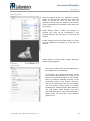
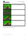
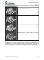
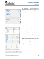
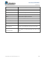
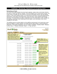
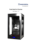
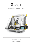
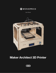
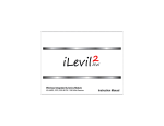
3DIM LABORATORY S.R.O. User Manual Revision 1.1 User Manual 3DimMaker Revision 1.1 Table of Contents 1. Installation ................................................................................................................ 2 1.1. Hardware requirements ...................................................................................... 2 2. 3D printing ................................................................................................................ 3 2.1. Input data ........................................................................................................... 3 2.2. Printing technology ............................................................................................. 3 2.3. G-code................................................................................................................ 4 2.4. Materials ............................................................................................................. 4 3. Let’s print our first model .......................................................................................... 5 3.1. Printer selection and settings ............................................................................. 5 3.2. Loading a model ................................................................................................. 6 3.3. Positioning the model ......................................................................................... 6 3.4. Selecting a print profile ....................................................................................... 7 3.5. Generating a G-code .......................................................................................... 7 3.6. Printing a G-code................................................................................................ 7 4. Program environment ............................................................................................... 8 4.1. Description of the environment and panels ........................................................ 8 5. Working with a model ............................................................................................. 16 5.1. Loading a model ............................................................................................... 16 5.2. Positioning the model ....................................................................................... 16 6. Generating a G-code from a model ........................................................................ 18 6.1. Adjusting profiles for printing ............................................................................ 18 6.2. Generating a G-code ........................................................................................ 18 6.3. Adjusting basic parameters .............................................................................. 18 7. Printing a G-code.................................................................................................... 20 7.1. Loading the material ......................................................................................... 20 7.2. Material management ....................................................................................... 20 8. Program settings .................................................................................................... 22 9. Printers supported .................................................................................................. 24 9.1. Specifying your own printer .............................................................................. 24 9.2. Printer calibration.............................................................................................. 25 10. G-code to model conversion parameters................................................................ 26 Copyright © by 3Dim laboratory s.r.o. 1 User Manual 3DimMaker Revision 1.1 1. Installation 3DimMaker supports the operating systems Windows Vista and higher and Mac OS X Lion and higher. Due to high memory requirements we recommend that you use a 64-bit operating system. 1.1. Hardware requirements Processor: at least dual core RAM: >4GB Mid-range dedicated video card, 512MB of video RAM Copyright © by 3Dim laboratory s.r.o. 2 User Manual 3DimMaker Revision 1.1 2. 3D printing 3D printing is a process in which a special printer creates a three-dimensional object from an appropriate material by laying it down in successive layers. A number of different printing technologies exist for 3D printing. At the current time, the most widespread and affordable method is thermoplastic extrusion. The advantage of 3D printing over classical machining is the possibility of creating shapes that could not be fabricated by any other method. 2.1. Input data Data for 3D printing are transferred to the application in the form of 3D models in the formats STL, OBJ, PLY, 3DS, and others. Not every 3D model is printable. A model must meet certain preconditions for 3D printing: - - The model should be closed. For an open model, it is not possible to distinguish the internal and external sides, so such a model will only be printed with a thin line without internal infills. The model should not contain details smaller than the print resolution. If it contains such details, the program usually only manages to print some of them and does not maintain the correct size for them. The model should not contain errors. If the model is composed of multiple open parts or overlapping triangles or contains poorly oriented normals, etc., the application will attempt to process the model, but the result may not correspond to what the user sees, may be lacking infill in some locations, may not be correctly supported, etc. 2.2. Printing technology On the basis of the settings selected by the user, which are restricted by the parameters of the printer, the model is converted into a series of slices. Printing paths are computed from these slices for the outlines of the model (perimeters), for the infill of the model, which increases its rigidity, and for supports for parts of the model which would “hang” in the air during printing. The result of this processing is a G-code. Copyright © by 3Dim laboratory s.r.o. 3 User Manual 3DimMaker Revision 1.1 2.3. G-code The term “G-code” refers to a sequence of instructions for machining tools. Because there are a number of variants, and there may be slight differences between manufactures, not every G-code will work with every printer. Therefore, it is advisable to process a model directly for a given printer. The G-code is closely linked with the current settings of the printer. Therefore, it is not possible to correctly print a G-code for a different extruder width, for instance. 2.4. Materials Two basic materials, ABS and PLA, are generally used for printing with the thermoplastic extrusion method. They are supplied in the form of filaments with a diameter of 1.75 to 3 mm. ABS – acrylonitrile butadiene styrene is a thermoplastic material. Its advantages are that it is firm, temperature and chemical resistant, and not harmful to health. Parts made from ABS can be bonded with solvent and polyacrylate adhesives. PLA – polyactid acid is obtained from renewable resources, namely from corn or potato starch, and is biodegradable. It is easier to process than ABS, but the products are less resistant to higher temperatures and already begin to get soft around 60°C. Products made from PLA are less elastic and glossier than those made from ABS. Copyright © by 3Dim laboratory s.r.o. 4 User Manual 3DimMaker Revision 1.1 3. Let’s print our first model 3DimMaker can be run in a simplified mode using a wizard or in an extended mode for advanced 3D printer users. It is possible to switch between these modes with the icon in the toolbar. In the simplified mode, a wizard panel is displayed in the application which combines the most important items for printing a model and, in a few steps from the user, goes through the entire process of preparing a G-code and printing. 3.1. Printer selection and settings The first step is the initial configuration of the printer. It is usually only necessary to adjust the printer settings the first time it is launched, and the wizard will not prompt this step later. ATTENTION! It is necessary to select not only the correct printer type, but also the port through which it is connected and the correct extruder diameter. When selecting the port, the printer must be connected to the computer and turned on! Copyright © by 3Dim laboratory s.r.o. 5 User Manual 3DimMaker Revision 1.1 3.2. Loading a model The second step is loading a model. In the simplified mode, it is only possible to load one model. If a model is already loaded, it will be deleted and replaced by the new model. If there is a G-code in the application, it will also be removed. The program can load models in the formats STL, OBJ, PLY, 3DS, and others. 3.3. Positioning the model The next step is positioning the model on the printer bed. 3DimMaker automatically positions the model in the middle of the printer bed and simultaneously deposits it on the print bed. If the model is too large, it then reduces it so it will fit in the print area. If we do not make any adjustments to the position or the scale, we can go directly to the next step. ATTENTION! If the changes made to the position of the model prevent it from being printed, the wizard will not allow you to go to the next step! Copyright © by 3Dim laboratory s.r.o. 6 User Manual 3DimMaker Revision 1.1 3.4. Selecting a print profile The fourth step is selecting the material and print profile. A material can be selected for each extruder. The list of available profiles is updated automatically according to the materials selected and the program settings for the extruder width entered. 3.5. Generating a G-code Clicking the Generate G-code button starts a computation that may last from tens of seconds to a few minutes, depending on the complexity and size of the model. Once the computation has finished, the G-code is displayed. The G-code display parameters can be adjusted with the Display preferences panel accessible from the View menu. 3.6. Printing a G-code Clicking the Print button initiates printing of the G-code. The print progress and estimated time till completion are continuously updated in the progress indicator on the status bar in the lower left part of the application window. Similarly, the display of the currently printed part of the model is continuously updated in the 3D window. ATTENTION! The printer does not begin printing immediately, because at the start, it needs to cross to the initial position and heat the extruder and printer bed to the working temperature! Copyright © by 3Dim laboratory s.r.o. 7 User Manual 3DimMaker Revision 1.1 4. Program environment 4.1. Description of the environment and panels The application consists of one main window that displays the virtual print surface of the 3D printer and the models located on this surface. Displayed panels may be located at the sides of this window. Their arrangement can be changed by dragging the titles of the panels. The toolbar is located in the upper part of the window. This can also be dragged to any location. By clicking the right-hand button on the toolbar, it is possible to adjust the visibility of other bars. Buttons for controlling the printer connection, preheating, and working with an SD card in the printer are located on the right side of the status bar if it is available. Copyright © by 3Dim laboratory s.r.o. 8 User Manual 3DimMaker Revision 1.1 Browser panel With the Browser panel, it is possible to browse folders and files and use the preview to select the model or G-code we want to load into the application and to process it. Display of the preview can be cancelled with the checkbox in the lower part of the panel. Single clicking selects a folder and displays its preview. The scene can be manipulated in the preview window in the same way as in the main 3D window. Double clicking loads the selected model or G-code into the application and displays it in the main 3D window. (Anais model is licensed under Creative Commons license by Fantasygraph) View panel The way the model and G-code are displayed can be changed with the View panel. In the upper part, display parameters of the print filament during display of a G-code can be adjusted. Its width and height can be changed, which are implicitly adjusted according to the parameters stored in the G-code. The entire style of the visualization can also be changed: very low quality (colored lines), low quality (shaded lines), medium quality (thick filament), and high quality (thick filament with more advanced shading). To work comfortably with a higher quality, you will need a more powerful graphics card. Copyright © by 3Dim laboratory s.r.o. 9 User Manual 3DimMaker Revision 1.1 Very low quality is suitable for analyzing the individual layers of the G-code. It is also not demanding for the hardware. Low quality is suitable for quickly previewing the entire G-code. Medium quality simulates the display of thick print filaments. It is appropriate for inspecting where individual filaments overlap. In terms of its use, high quality is equivalent to medium quality, but the filaments are displayed with better shading. The visualization method of the loaded model can also be switched on the panel. The options are flat shading, smooth shading, wireframe, and wireframe-Z. Copyright © by 3Dim laboratory s.r.o. 10 User Manual 3DimMaker Revision 1.1 Flat shading is appropriate for models with a large number of sharp angles and large flat surfaces. Smooth is appropriate for models with rounded parts. Wireframe displays a wireframe model. Wireframe-Z displays a wireframe model but respects the visibility as when displaying the full model. In the bottom part of the panel, it is possible to restrict the display of the G-code and display only some of its layers. The first layer displayed and the number of following layers are specified. The visibility of the supports, infills, and crossings of the printer head can also be switched optionally. Copyright © by 3Dim laboratory s.r.o. 11 User Manual 3DimMaker Revision 1.1 Wizard panel The wizard panel is for basic control of the application by regular users. In a few steps from the user, it goes through loading a model, selecting the print profile, preparing the G-code, and finally printing the end-product. Objects panel If the Advanced settings selection is active, the user has access to the Object panel, which is used to manage loaded models and G-codes. A list of models and G-codes with their basic properties is displayed in the upper part. Next to each object there is a checkbox which can be used to display or hide the given object. The properties of the object can be displayed by clicking on the arrow to the left of the name of the object. Models can be manipulated with this panel using a series of buttons and sliders. With them, the model can be rotated along several axes, moved, or scaled. When changing the scale, it is possible to force the size to be increased uniformly or along individual axes. The scale can also be changed by entering exact values into the number fields. Under the transformations, there are buttons for: Copyright © by 3Dim laboratory s.r.o. 12 User Manual 3DimMaker Revision 1.1 depositing the model on the print bed centering the model on the bed positioning the model according to three points that are entered positioning the model according to a polygon that is entered resetting the transformations After clicking the button, positioning according to three points or a polygon is accomplished by holding down the Shift key and clicking on the model. For the three-point method, small balls will start to appear at the marked locations. After marking the third one, the model is positioned and the balls disappear. For positioning according to a polygon, only one location needs to be marked. The model then turns so that the selected polygon or three points lie even with the bed. Resetting the transformations cancels all transformations performed on the model so far and positions it at the start of the coordinate system. Copyright © by 3Dim laboratory s.r.o. 13 User Manual 3DimMaker Revision 1.1 Manual control panel This panel allows the user to directly control the connected printer by hand. Control elements for manipulating the extruders and heater are located in the upper part. Below them is a control cross for moving the printer head along individual axes. Besides this, it is possible to send the head to the so-called Home position. Cooling can also be controlled. An important function that is accessible from this panel is the wizard for loading the material. It is also possible to influence its speed and printing temperature while printing. Copyright © by 3Dim laboratory s.r.o. 14 User Manual 3DimMaker Revision 1.1 Printing profiles panel The conversion of a model to a G-code has a number of adjustable parameters that are combined into printing profiles. The application contains both special profiles tailored to specific printers and materials and general profiles which have to be customized with input from the user. ATTENTION! For profiles supplied with the application, it is possible to view the parameters and change only the most basic ones. If you would like to make more advanced adjustments to the settings, you must select the corresponding basic profile and duplicate it! Every profile can be temporarily overridden. You can add, remove and adjust overriding parameters after you enable this feature with Apply checkbox. Copyright © by 3Dim laboratory s.r.o. 15 User Manual 3DimMaker Revision 1.1 5. Working with a model 5.1. Loading a model A model can be loaded with the Load model command from the File menu or by double clicking on the selected file in the browser window, which can be displayed with a command from the View menu. The supported model formats are STL, OBJ, PLY, 3DS, and others. For correct processing, the model should be closed, with non-overlapping parts, with details corresponding to the print quality, and with correctly adjusted normals. If any of these conditions are not met, you can attempt to fix the model after it has loaded with the Fix command from the context menu on the model element in the Objects panel. For larger fixes, we recommend using one of the special online services or making the fixes manually in the 3D modeling software. Since model processing for 3D printing makes significant demands on processor performance and memory, it is advisable to ensure that the model is not excessively detailed. 5.2. Positioning the model A loaded model can be selected by clicking the left mouse button in the 3D scene on the selected model. Multiple models can be selected simultaneously by holding down the Shift key at the same time. The selection of models can be canceled in steps with the Ctrl key. The selected models can then be moved. If necessary, it is possible to rotate them or change their size using the draggers. To make it easier to rotate the model by a right angle, make a precise scale change, and place it, there are control elements in the print wizard or in the Object panel in expert mode for rotating by one degree or 90 degrees, for moving the model along the print surface, and for changing the scale by a given value. In addition, the model can be placed on the print surface in the current position or according to the selected position, according to three selected points on the model if necessary. Copyright © by 3Dim laboratory s.r.o. 16 User Manual 3DimMaker Revision 1.1 When positioning multiple models at once, the application distinguishes the selected positions by color, where the positions of the models are limited by the projections of their convex envelopes. Copyright © by 3Dim laboratory s.r.o. 17 User Manual 3DimMaker Revision 1.1 6. Generating a G-code from a model Before printing the model, it is necessary for the application to slice the model into print layers and compute printing path for printing both the actual outline of the model and the infills and support structures. The result of this processing is a G-code, a sequence of instructions for the printer. 6.1. Adjusting profiles for printing Before generating a printing code, it is necessary to tell the application how many extruders, what material, and what print profile you want to print the model with. The number of extruders is given by the printer you have. If you have a printer with multiple extruders, it is of course possible to use only some of them. Select the material according to what you have and what there are pre-prepared print profiles for. The selection of profiles that can be used for a given number of extruders and extruder dimensions in combination with the material used is automatically updated when the parameters are changed. Select a profile from the available profiles corresponding to the quality with which you would like to print the model. A higher quality generally means longer preparation of the G-code and of the printing itself. In the advanced settings mode, all the settings of the selected profile can be displayed, and certain basic ones can be adjusted. Alternatively, it is possible to create your own copy of the profile where you can adjust a whole series of parameters. However, if the settings are inappropriate, this may lead to an result that is unprintable, even if everything looks fine when you display it in the application. 6.2. Generating a G-code You can generate a G-code for the selected settings by clicking the Generate G-code button. The computation can last from a few seconds to tens of minutes depending on the size and complexity of the model and the settings selected. The G-code created can be saved with the corresponding selection from the File menu; the G-code can be reloaded with the Load G-code command from the same menu or by double clicking on the selected file in the browser window, which can be displayed with the command from the View menu. The generated G-code is customized for the given settings and the printer selected, since it is generally not advisable to transfer a code elsewhere once it has already been generated. 6.3. Adjusting basic parameters Perimeters – these are print paths running along the outline of the object; they define the basic consistency of the object. Infill density – increases the rigidity of the object. 10% infill already gives the object sufficient rigidity and saves a lot of material. Supports – these are the support structure for printing parts of the model that are not reinforced by anything. After the model is printed, they have to be broken off by hand, or, if multiple materials are Copyright © by 3Dim laboratory s.r.o. 18 User Manual 3DimMaker Revision 1.1 used, they can be removed by chemical means. Although the supports are separated from the shape by small gaps, they sometimes require greater force to break off. Extruder settings – determine which extruder will be used for printing the given type of geometry. Copyright © by 3Dim laboratory s.r.o. 19 User Manual 3DimMaker Revision 1.1 7. Printing a G-code Once you have a G-code generated for printing and have loaded the material into the printer, you can start printing. The printer does not begin printing immediately, because at the start, it needs to cross to the initial position and heat the extruder and print bed to the working temperature. The print progress and estimated time till completion are continuously updated in the progress indicator on the status bar in the lower left part of the application window. Similarly, the display of the currently printed part of the model is continuously updated in the 3D window. Printing in progress can be paused, usually for the purpose of replacing the material, and can be stopped completely if necessary. If the application crashes during printing or a similar error state arises, the application can offer the user to resume printing from the last recorded position. Since the printer contains its own cache, the last recorded position may not correspond exactly to the actual end of printing. Furthermore, the printer will need to calibrate at least the X and Y axes in order to continue printing. Therefore, we recommend only using this function in an emergency. 7.1. Loading the material You can find the wizard for loading the material in the manual control panel. Once the dialog box opens, the associated extruder immediately starts to heat up to the temperature entered in the program settings. While it is heating up, you can disconnect the guiding tube from the extruder head, cut off the old material, and pull a new tube through in its place. Once the required extruder temperature is reached, click the Load material button, and the printer will start to push the heated material thorough the head. Push a new filament with material into the extruder head. After loading the material, click the Load material button again to turn of the extruder motor and insert the guiding tube back into the head. 7.2. Material management To make it easier to manage printing materials, the application makes it possible to enter material packs in the program settings along with information on their lengths. If you then select the Copyright © by 3Dim laboratory s.r.o. 20 User Manual 3DimMaker Revision 1.1 corresponding material pack as the source for the given extruder, the application will automatically subtract the material used during printing and warn you before printing if the quantity of material is insufficient for printing the selected object. Copyright © by 3Dim laboratory s.r.o. 21 User Manual 3DimMaker Revision 1.1 8. Program settings When you click on View – Preferences in the application menu, a dialog box with settings opens. The language of the application, the style used, different colors for windows and G-codes, and the style of scene manipulation and control can be selected on the General tab. On the Advanced tab you can enable logging the state of the application, antialiasing for drawing, display of warning messages in potential error states, and automatic checks for application updates. Copyright © by 3Dim laboratory s.r.o. 22 User Manual 3DimMaker Revision 1.1 On the printer tab you can set the printer parameters with which you would like to print. Here you can select the printer type, the port via which the printer communicates, and the extruder width. It is then possible to adjust the area for purging the extruder and the heating temperature right before printing. Finally, actions can be defined that have to be performed when printing stops. Copyright © by 3Dim laboratory s.r.o. 23 User Manual 3DimMaker Revision 1.1 9. Printers supported Printing has been tested on Aroja printers, but in principle it should function on all printers that work via a serial port or a virtual serial port and communicate in the standard way. 9.1. Specifying your own printer In the program settings it is possible to open a dialog box for adding your own printer. When specifying a printer, it is necessary to enter not only its dimensions but also the communication parameters. If you’re unsure, try keeping the defaults, or try to find a printer among the supported printers that uses the same or similar electronics. After specifying your own printer, only generic profiles will be available to you which may not allow printing to achieve optimal results. Therefore, it may be necessary to create copies of existing profiles and customize their printing parameters. Copyright © by 3Dim laboratory s.r.o. 24 User Manual 3DimMaker Revision 1.1 9.2. Printer calibration The current version of the program only supports calibration of the size of the objects printed. After opening the calibration panel with the Calibrate command from the Print menu, you will be able to print a calibration object; you enter its measured dimensions into the panel and perform the calibration. Copyright © by 3Dim laboratory s.r.o. 25 User Manual 3DimMaker Revision 1.1 10. G-code to model conversion parameters Printer properties G-Code arcs Use G2/G3 commands for native arcs (experimental, not supported by all firmwares) Filament properties Filament diameter Diameter in mm of your raw filament (default: 3) Extrusion temperature Extrusion temperatures in degrees Celsius; set to 0 to disable; to specify multiple temperatures, use ';' as separator (default: 200) First layer extrusion temperature Extrusion temperature for the first layer, in degrees Celsius. Set to 0 to disable (default: same as --temperature) Bed temperature Heated bed temperature in degrees Celsius; set to 0 to disable (default: 0) First layer bed temperature Heated bed temperature for the first layer, in degrees Celsius; set to 0 to disable (default: same as --bed-temperature) Extrusion multiplier Change this to alter the amount of plastic extruded. There should be very little need to change this value, which is only useful to compensate for filament packing (default: 1) Extrusion formula Selection of the formula for calculation of amount of the extruded material (value : 0 or 1, default: 0) Speed properties Travel speed Speed of non-print moves in mm/s (default: 130) Perimeter speed Speed of print moves for perimeters in mm/s (default: 30) Small perimeter speed Speed of print moves for small perimeters in mm/s or % over perimeter speed (default: 30) External perimeter speed Speed of print moves for the external perimeter in mm/s or % over perimeter speed (default: 70%) Infill speed Speed of print moves in mm/s (default: 60) Support speed Speed of support material print moves in mm/s (default: 60) Bridge speed Speed of bridge print moves in mm/s (default: 60) Copyright © by 3Dim laboratory s.r.o. 26 User Manual 3DimMaker Revision 1.1 First layer speed Speed of print moves for bottom layer, expressed either as an absolute value or as a percentage over normal speeds (default: 30%) Accuracy properties Layer height Layer height in mm (default: 0.4) First layer height Layer height for first layer (mm or %, default: 100%) Infill every N layers Infill every N layers (default: 1) Print properties Number of perimeters Number of perimeters/horizontal skins (range: 0+, default: 3) Number of top layers Number of solid layers to do for top surfaces (range: 0+, default: 3) Number of bottom layers Number of solid layers to do for bottom surfaces (range: 0+, default: 3) Fill density Infill density (range: 0–1, default: 0.4) Fill angle Infill angle in degrees (range: 0–90, default: 45) Fill minimum spacing Minimum spacing between pattern lines (in mm, default: 0) Fill pattern Pattern to use to fill non-solid layers (default: rectilinear) Solid fill pattern Pattern to use to fill solid layers (default: rectilinear) Use outer solid layer fill Use perimeters to fill outermost solid layer Perimeter fill dissolve factor Factor that affects dissolving of inner perimeter and infill into each other First perimeter dissolve factor Factor that affects dissolving of first perimeter's start and end Perimeter dissolve factor Factor that affects dissolving of perimeter's start and end Avoid fill retracts Minimizes retractions during fill printing (similar to --onlyretract-when-crossing-perimeters) Avoid support retracts Minimizes retractions during support print Avoid perimeter retracts Minimizes retractions during perimeter print Outer perimeter first Outer perimeter will be printed first if checked, inner Copyright © by 3Dim laboratory s.r.o. 27 User Manual 3DimMaker Revision 1.1 perimeter will be printed first otherwise Dense fill area Geometry with smaller area will get double fill density (default:50) Keep start points Attempts to keep start/end points of printed geometry close to those in lower layers Start G-Code Load initial G-code from the supplied file. This will overwrite the default command (home all axes [G28]). End G-Code Load final G-code from the supplied file. This will overwrite the default commands (turn off temperature [M104 S0], home X axis [G28 X], disable motors [M84]). Layer G-Code Load layer-change G-code from the supplied file (default: nothing). Tool change G-Code 1 Load tool-change G-code which is performed just before tool change from the supplied file (default: nothing). Tool change G-Code 2 Load tool-change G-code to be performed after tool change finished from the supplied file (default: nothing). Support properties Support material Generate support material for overhangs Support threshold angle Overhang threshold angle (range: 0–90; set to 0 for automatic detection; default: 0) Pattern Pattern to use for support material (default: rectilinear) Interface layers Number of perpendicular layers between support material and object (0+, default: 0) Vertical Interface layers Number of layers between support material and object (0+, default: 0) Spacing Spacing between pattern lines (in mm, default: 2.5) Angle Support material angle in degrees (range: 0–90, default: 0) Against bed only No supports between model parts will be generated, only supports against print bed Optimize Performs additional checks of supports to reduce errors (default: true) Copyright © by 3Dim laboratory s.r.o. 28 User Manual 3DimMaker Revision 1.1 Dense fill threshold Max supports area which will get dense fill (default: 100) Skeleton dense fill Turns on polygon-axis-based dense fill. Uses double density support fill if not on (default: true) Number of raft layers Number of layers to raise the printed objects by (range: 0+, default: 0) Brim Turns on brim for supports that are distant enough from model body (default: false) Trunk like base Turns on trunk-like supports base (default: false) Top Layer Extrusion Factor Extrusion factor for the top layer of supports (range: 0–1, default: 1) Support every N layers Support every N layers (default: 1) Retraction properties Retract length Length of retraction in mm when pausing extrusion (default: 1) Retract speed Speed for retraction in mm/s (default: 30) Move lift Lift Z by the given distance in mm or % of layer height when retracting and moving (default: 200%) Retract before travel Only retract before non-print moves of this length in mm (default: 0) Retract restart extra Additional amount of filament in mm to push after compensating retraction (default: 0) Retract restart tool change Additional amount of filament in mm to push after switching tool (default: 0) Early retract Distance before polygon end where extrusion finishes and retraction starts (default: 0) Cooling properties Cooling enabled Enable fan and cooling control Slowdown below layer time Slow down if layer print time is below this approximate number of seconds (default: 30) Fan below layer time Enable fan if layer print time is below this approximate Copyright © by 3Dim laboratory s.r.o. 29 User Manual 3DimMaker Revision 1.1 number of seconds (default: 60) Minimum print speed Minimum print speed (mm/s, default: 10) Minimum fan speed Minimum fan speed (default: 35%) Maximum fan speed Maximum fan speed (default: 100%) Bridge fan speed Fan speed to use when bridging (default: 100%) Disable fan first layers Disable fan for the first N layers (default: 1) Fan always on Always keep fan on at min fan speed, even for layers that don't need cooling Skirt properties Skirts to draw Number of skirts to draw (0+, default: 1) Skirt distance Distance in mm between innermost skirt and object (default: 6) Skirt height Height of skirts to draw (expressed in layers, 0+, default: 1) Brim width Width of the brim that will get added to each object to help adhesion (mm, default: 0) Flow properties Extrusion width Set extrusion width manually; it accepts either an absolute value in mm (like 0.65) or % of extruder width. First perimeter offset Offset of the first perimeter in mm (default: 0) Bridge properties Bridges Build bridges (default: true) Bridge overlap Set bridge-model overlap; it accepts an absolute value in mm Max bridge length Set maximum bridge length; it accepts an absolute value in mm Extruder properties Perimeter extruder Extruder to use for perimeters (1+, default: 1) Infill extruder Extruder to use for infill (1+, default: 1) Copyright © by 3Dim laboratory s.r.o. 30 User Manual 3DimMaker Revision 1.1 Support material extruder Extruder to use for support material (1+, default: 1) Transform properties Auto-drop Drop model on printbed Rotate-x Model rotation in degrees around X axis Rotate-y Model rotation in degrees around Y axis Rotate-z Model rotation in degrees around Z axis Scale Factor for scaling input object (default: 1) Additional properties Repair model Try to fix model Thin parts Enable thin parts Vertex merge limit Threshold for merging vertices together (this may fix open models; it can also break them even more in some cases). Line connection limit Threshold for connecting lines with isolated ends (this may fix open models; it can also break them even more in some cases). Copyright © by 3Dim laboratory s.r.o. 31