1
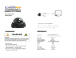
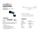
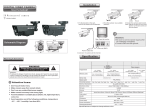
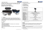
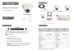
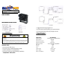
DIGITAL VIDEO CAMERA
User's Manual
SKU# 15-CG30A
Black & White Pin Hole Camera
• Suggested mounting height 8'-12'
• Do not mount camera directly to a metal surface
• Do not point camera directly into light sources
WARNING
Attention:
To reduce the danger of electric shock, please do not open the case (or back
cover) of camera; everything needed for user operation is on the surface of
the camera; please seek help from a qualified professional for repair.
Attention items:
• Do not touch CCD or lens
• Do not use any unidentified power supply
• Avoid installation in unstable places
• Do not use camera in the following conditions,
Temperature: -20⁰C/+50⁰C
Image Sensor
Effective Pixels
Signal system
Horizontal resolution
Minimum illumination
Electronic shutter
S/N ratio
Gamma
Lens
Video output
Power supply
Power consumption
1/3" SONY CCD
E:510(H)x492(V) C:5000(H)x582(V)
EIA/CCIR
330TVL
0.05Lux/F2
Auto:1/50(1/60)-1/100,000Sec
>48dB
0.45
3.6mm
1.0Vp-p, 75Ω
DV 12V±5%
200mA
Making a BNC Connection
Connecting a Pre-made Cable
Step 1: Strip away all of the cable and shielding so
you have 1/2" of the center conductor exposed as
shown in the picture.
Connect this end to
the camera.
Step 2: Then strip away the black outer jacket so
you have 1/4" of the shielding exposed. Do not
allow any of the copper shielding to touch the
center conductor.
The cables are labeled with a yellow wrap detailing the camera end
and the DVR end. It is very important that you identify these ends
before installing the cable so that you have the correct ends at the
correct location.
Step 3: Insert the cable into the fitting and gently
find the hole for the center conductor before you
press the fitting onto the wire. Now just twist the
fitting onto the wire while firmly pressing down
until the fitting is firmly on the cable.
Installing a power wire pigtail
Step 1: At the camera location, take the power
cable and strip away the outer sheathing to
expose the inner two wires (black & red). Then
strip away about 1/4" of the wires jacket to
expose the copper wire. Do the same to the
power wire pigtail which connects to the camera
power connection as shown. Note: Do not strip or
cut the power lead coming directly from the
camera. You should strip the "pigtail" power
cable which came with your kit. You should have
one "pigtail" for each camera.
Step 2: Now take the red power cable lead and
twist it together with the black & white lead from
the power pigtail. Now take the black lead from
the power cable and twist it together with the all
black lead from the pigtail. Use the gray wire nuts
provided with your system and twist them onto
the wires until they are firmly secured.
Contact
EZWATCHPRO
www.ezwatch-security-cameras.com
Phone/Fax
Technical Support/Sales
Toll Free 1-866-241-3400
International 001-801-4783980
Fax 1-801-295-2191
Mail
Main Office/Mailing Address
Automated Video Systems
1600 S. State Street
Salt Lake City, UT 84115