1
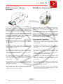
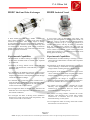
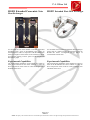
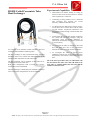
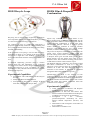
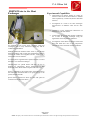
P.A.Hilton Ltd Heat Exchanger Service Unit H102 H102 shown fitted with H102C Shell & Tube Heat Exchanger 11 types of Heat Exchangers can be used on the H102 Service Unit. Safe and Suitable For Unsupervised Student Operation. Responds Rapidly to Control Changes. Negligible Operating and Maintenance Costs. Optional Computerised Data Acquisition Upgrade Two year Warranty. Page 1 of 11 Edition 5 NOTE: The policy of P.A.Hilton Ltd is one of continual improvement and we reserve the right to change this specification without notice. P.A.Hilton Ltd Introduction Heat Exchangers are a vital component in many industrial processes enabling heat to be transferred from one fluid to another. Four of the most common types found in industry are Concentric Tube, Shell and Tube, Plate and Jacketed Vessel. Student engineers need to be aware of the characteristics of these and other heat exchangers if they are to be involved in the design, operation or service of any heat transfer process. The Hilton Heat Exchanger Service Unit is bench mounted, fully instrumented and operates from conventional single phase electrical supply and mains water. Using optional modules, the Service Unit enables students to investigate the performance of each of these common heat exchangers and their variants. The unit will be of particular interest to those studying: Mechanical Engineering Nuclear Engineering Chemical Engineering Control and Instrumentation Plant and Process Engineering Building Services Engineering Physics Refrigeration Marine Engineering Experimental Capabilities For detailed descriptions and experimental capabilities refer to individual data sheets for each optional heat exchanger. Description Heat Exchanger Service Unit H102 (Shown with Optional H102C Fitted) A bench mounted, reinforced plastic panel with an integral electrical console that provides services for any of the optional heat exchangers. Temperature controlled hot water is provided from an electrically heated tank by a continuously rated fixed speed pump. Mains cold water is pressure regulated. Hot and Cold flow is controlled and measured using variable area flowmeters. The optional heat exchangers are connected to the service unit using non-drip, self-sealing couplings. Electrical safety is provided by double pole overload and earth leakage circuit breakers. The hot water system is equipped with a safety temperature limiting device. The standard instrumentation consists of up to 12 type T thermocouples, displayed on a digital panel meter, and two flowmeters for hot and cold fluids. These enable all relevant heat transfer calculations to be made. Optional Heat exchangers in some cases add other measurement configurations. An optional Computerised Data Acquisition Upgrade HC103A is available to allow all available parameters to be recorded on a computer in real time. Page 2 of 11 Edition 5 NOTE: The policy of P.A.Hilton Ltd is one of continual improvement and we reserve the right to change this specification without notice. P.A.Hilton Ltd Specification Services Required Heat Exchanger Service Unit H102 Electrical: A: General A fully instrumented bench top heat exchanger service unit providing circulated hot water and controlled cold water flows for many types of individual optional heat exchangers. Optional computerised data acquisition of all measured parameters available. Detailed A bench mounted heat exchanger service unit comprising a reinforced plastic instrument panel with electric water heater and circulating pump providing temperature controlled hot water from self-sealing quick release couplings. Controlled and measured cold water is taken from the local supply. Internal electric and mechanical safety devices to allow for unsupervised operation by students. Instrumentation to measure up to 12 temperatures and the relevant flow rates of the hot and cold fluids through the heat exchanger under test. Optional Heat Exchangers Include:Concentric Heat Exchanger H102A Plate Heat Exchanger H102B Shell & Tube Heat Exchanger H102C Jacketed Vessel H102D Extended Concentric Heat Exchanger H102E Extended Plate Heat Exchanger H102F Water to Water Turbulent Flow Heat Exchanger (Nu, Re, Pr Investigation) H102G Coiled Concentric Tube Heat Exchanger H102H Recycle Loops H102J Film and Dropwise Condensation H102K Water to Air heat Exchanger H102M Supplied with a detailed experimental operating and maintenance manual giving example experimental results and sample calculations. Accessories and spares for two years normal operation together with a full two year warranty. Optional computerised data acquisition of all measured parameters is available with a 21 channel data logger and menu driven software. Refer to the optional Heat Exchanger specifications for detailed capabilities Dimensions Height: 760mm Width: 760mm Depth: 485mm Weight: 39kg. B: 220-240 Volts, Single Phase, 50Hz (With earth/ground). Line current up to13A at 230v 110-120 Volts, Single Phase, 60Hz (With earth/ground). Line current up to 26A at 110v Water: 3 litres m-1 at a minimum of 10m head. Open drain for this flow rate. Accessories and Spares Unit supplied with: One experimental operating and maintenance manual in either English, Spanish or French. Accessories and spares for 2 years normal operation. List available on request. Ordering Information Order as: Heat Exchanger Service Unit H102 Electrical Specification Either: A: 220-240 Volts, Single Phase, 50Hz (With earth/ground). B: 110-120 Volts, Single Phase, 60Hz (With earth/ground). Language Either: English, Spanish, French. Optional Heat Exchangers, Order as: Concentric Heat Exchanger Plate Heat Exchanger Shell & Tube Heat Exchanger Jacketed Vessel Extended Concentric Heat Exchanger Extended Plate Heat Exchanger Water to Water Turbulent Flow Heat Exchanger Coiled concentric Tube Heat Exchanger Recycle Loops Film and Dropwise Condensation Water to Air heat Exchanger H102A H102B H102C H102D H102E H102F H102G H102H H102J H102K H102M Shipping Specifications Service Unit H102 Net Weight: Approximate Gross Weight: Packing Case Dimensions:Packing Case Volume: 39kg. 82kg. 0.92 x 0.65 x 1.05m 0.32m3 For shipping details of the optional heat exchangers please refer to P.A.Hilton Ltd. Also Available On Request Further detailed specification. Additional copies of instruction manual. Recommended list of spares for 5 years operation. Page 3 of 11 Edition 5 NOTE: The policy of P.A.Hilton Ltd is one of continual improvement and we reserve the right to change this specification without notice. P.A.Hilton Ltd H102A Concentric Tube Heat H102B Plate Heat Exchanger Exchanger A clear acrylic tube containing cold water surrounds an inner stainless steel tube in which the hot water flows. Total heat transfer area of approximately 24000mm2. Six thermocouples measure hot and cold inlet, mid-point and exit temperatures. Self-sealing quick release connections enable rapid connection to the H102 and conversion from parallel to counter current flow. An extended version with 3 pairs of intermediate points and a total of 10 thermocouples is also available as H102E. Multiple brazed stainless steel plates arranged for multipass operation with passes in series give a total heat transfer area of approximately 24000mm2. Four thermocouples measure hot and cold fluid entry and exit temperatures. Self-sealing quick release connections enable rapid connection to the H102 and conversion from parallel to counter-current flow. An extended version with intermediate measuring points and a total of 6 thermocouples is available as H102F. Experimental Capabilities Experimental Capabilities Demonstration of indirect heating or cooling by transfer of heat from one fluid stream to another when separated by a solid wall Demonstration of indirect heating or cooling by transfer of heat from one fluid stream to another when separated by a solid wall Conducting an energy balance across a concentric tube heat exchanger and calculate the overall efficiency at different fluid flow rates. Conducting an energy balance across plate exchanger and calculate the overall efficiency at different fluid flow rates. To demonstrate the differences between counter-current flow and co-current flows and the effect on heat transfer, temperature efficiencies and temperature profiles through a concentric tube heat exchanger. To demonstrate the differences between counter-current flow and co-current flows and the effect on heat transfer, temperature efficiencies and temperature profiles through a plate heat exchanger. To determine the overall heat transfer coefficient for a concentric tube heat exchanger using the logarithmic mean temperature difference for counter-current and cocurrent flows. To determine the overall heat transfer coefficient for a plate heat exchanger using the logarithmic mean temperature difference for counter-current and cocurrent flows. To investigate the effect of changes in hot fluid and cold fluid flow rate on the temperature efficiencies and overall heat transfer coefficient. To investigate the effect of changes in hot fluid and cold fluid flow rate on the temperature efficiencies and overall heat transfer coefficient. To investigate the effect of driving force (difference between hot stream and cold stream temperature) with counter-current and co-current flow To investigate the effect of driving force (difference between hot stream and cold stream temperature) with counter-current and co-current flow Page 4 of 11 Edition 5 NOTE: The policy of P.A.Hilton Ltd is one of continual improvement and we reserve the right to change this specification without notice. P.A.Hilton Ltd H102C Shell and Tube Exchanger H102D Jacketed Vessel A thick walled glass shell with 2 baffles contains cold water, which passes over 7 stainless steel tubes through which hot water flows. Tube bundle length of 205mm giving total heat transfer area of approximately 24000 mm2. Four thermocouples measure hot and cold fluid entry and exit temperatures. Self-sealing quick release connections enable rapid connection to the H102 and conversion from parallel to counter-current flow. A vessel with a clear top has a glass outer jacket. Hot water may pass through this or through a heat transfer coil inside the vessel to provide external or internal heating. The vessel contents of up to 2 litres are agitated by a variable speed stirrer, and may be batch or continuous feed. Six thermocouples measure hot inlet and exit temperatures from the jacket and coil, cold fluid inlet and vessel contents temperatures. Quick release connections enable rapid connection to the H102 and conversion from heating jacket to heating coil. Experimental Capabilities Experimental Capabilities Demonstration of indirect heating or cooling by transfer of heat from one fluid stream to another when separated by a solid wall. Demonstration of indirect heating or cooling by transfer of heat from one fluid stream to another when separated by a solid wall. Conducting an energy balance across a shell and tube exchanger and calculate the overall efficiency at different fluid flow rates Investigation of the heating characteristics of a stirred vessel containing a fixed batch of liquid when heated using hot fluid circulating through a submerged coil. To demonstrate the differences between counter-current flow and co-current flows and the effect on heat transfer, temperature efficiencies and temperature profiles through a shell and tube heat exchanger. Investigation of the heating characteristics of a stirred vessel containing a fixed batch of liquid when heated using hot fluid circulating through an outer jacket. To determine the overall heat transfer coefficient for a shell and tube heat exchanger using the logarithmic mean temperature difference to perform the calculations (for counter-current and co-current flows). To investigate the effect of changes in hot fluid and cold fluid flow rate on the temperature efficiencies and overall heat transfer coefficient. To investigate the effect of driving forces (difference between hot stream and cold stream temperature) with counter-current and co-current flow. To investigate the change in overall heat transfer coefficient and logarithmic mean temperature difference as a batch of fluid in the vessel changes temperature. To perform an energy balance, calculate the overall efficiency and determine the overall heat transfer coefficient for a continuous flow in a stirred vessel when heated using a submerged coil. To perform an energy balance, calculate the overall efficiency and determine the overall heat transfer coefficient for a continuous flow in a stirred vessel when heated using an outer jacket. To investigate the effect of stirring on the heat transfer characteristics of a stirred vessel. Page 5 of 11 Edition 5 NOTE: The policy of P.A.Hilton Ltd is one of continual improvement and we reserve the right to change this specification without notice. P.A.Hilton Ltd H102E Extended Concentric Tube H102F Extended Plate Heat Exchanger Heat Exchanger An extended version of the H102A Concentric Tube Heat Exchanger with 3 pairs of intermediate points giving 10 thermocouples in total. In conjunction with the H102A this allows investigation of the effects of increased heat transfer area and the plotting of more points on the temperature distribution graph. An extended version of the H102B Plate Heat Exchanger with a total of 6 thermocouples. In conjunction with the H102B this allows investigation of the effects of increased heat transfer area Experimental Capabilities Experimental Capabilities The experimental capabilities of the H102E are similar to those of the H102A but also allow students to make the direct comparison of test results on a heat exchanger with a doubled surface area. The experimental capabilities of the H102F are similar to those of the H102B but also allow students to make the direct comparison of test results on a heat exchanger with a doubled surface area. Page 6 of 11 Edition 5 NOTE: The policy of P.A.Hilton Ltd is one of continual improvement and we reserve the right to change this specification without notice. P.A.Hilton Ltd H102G Water-Water Turbulent Flow Heat Exchanger Experimental Capabilities Determination of heat transfer rate, logarithmic mean temperature difference, overall heat transfer coefficient and 4 point hot and cold stream temperature profiles. Determination of surface heat transfer coefficient inside and outside the tube, and of the effect of fluid velocity. Comparison of performance in concurrent and in counter-current flow. Investigation of the relationship between Nusselt (Nu), Reynolds (Re) and Prandtl (Pr) Numbers for Reynolds Numbers up to 65000 and for Prandtl Numbers between 2.5 and 5.0. Determination of the constants in Nu = k Rea Prb. This is a highly advanced concentric tube heat exchanger with hot water flowing through the central tube while cooling water flows through the annular space. The heat exchanger has been divided into three equal sections in order to allow examination of the intermediate stream temperature conditions and temperature distribution through the heat exchanger. Thermocouples sense the hot and cold stream temperatures at the four stations and the inner tube wall temperatures on entry and exit. The addition of the central tube surface temperatures at inlet and exit allow detailed investigation of the surface heat transfer coefficient inside and outside the central tube. This allows advanced students to investigate the Nusselt, Reynolds, Prandtl relationship Nu = k Rea Prb. The core tube temperatures also allow students to plot hot stream, cold stream and core tube temperatures for both con-current and counter-current flow. The unit incorporates an extended range flowmeter in order to allow investigation of low and high range Reynolds numbers. The PID temperature control on the H102 Heat Exchanger Service Unit allows investigation of turbulent flow conditions at a range of fixed Prandtl numbers. Investigations using these two methods of control allow students to experimentally determine the constants in one of the classic empirical equations for turbulent heat transfer in a tube. Nu = 0.023 Re0.8 Pr0.4 Page 7 of 11 Edition 5 NOTE: The policy of P.A.Hilton Ltd is one of continual improvement and we reserve the right to change this specification without notice. P.A.Hilton Ltd H102H Coiled Concentric Tube Heat Exchanger Experimental Capabilities Demonstration of indirect heating or cooling by transfer of heat from one fluid stream to another when separated by a solid wall. Conducting an energy balance across a shell and tube exchanger and calculate the overall efficiency at different fluid flow rates To demonstrate the differences between countercurrent flow and co-current flows and the effect on heat transfer, temperature efficiencies and temperature profiles through a shell and tube heat exchanger. To determine the overall heat transfer coefficient for a shell and tube heat exchanger using the logarithmic mean temperature difference to perform the calculations (for counter-current and co-current flows). To investigate the effect of changes in hot fluid and cold fluid flow rate on the temperature efficiencies and overall heat transfer coefficient. The heat exchanger is fully instrumented using the Heat Exchanger Service Un it H102 with thermocouples on the inlet and outlet of both the hot and cold streams. To investigate the effect of driving forces (difference between hot stream and cold stream temperature) with counter-current and co-current flow. The heat exchanger can be arranged so that either hot or cold streams are in the inner tube. With either configuration both co-current and countercurrent flow can be established. All of the above procedures may be undertaken with the hot fluid in the inner tube and cold fluid in the outer tube; or, with hot fluid in the outer tube and the cold flow in the inner tube. An example of an industrial coiled concentric tube heat exchanger with turbulence enhancing tubes. The heat exchanger is deliberately not insulated so that heat losses in all of the configurations can be investigated. Page 8 of 11 Edition 5 NOTE: The policy of P.A.Hilton Ltd is one of continual improvement and we reserve the right to change this specification without notice. P.A.Hilton Ltd H102J Recycle Loops H102K Film & Dropwise Condensation Recycling can be used in many engineering applications and is important when applied to thermodynamic processes as it can result in reduced energy requirements. Vapour may condense onto a cooled surface in two distinct modes known as filmwise and dropwise. For the same temperature difference between the vapour and the surface, dropwise condensation is several more times effective than filmwise. However it involves special surface finishes or treatment in order to maintain dropwise condensation and for this reason, though desirable, it seldom occurs in real plant operation. The process of dropwise condensation is enhanced by the special water cooled condenser surface finish that prevents wetting of the surface. Condensation then occurs in droplets which grow and fall under gravity. These falling droplets wipe the surface clean ready for more droplets to form. This continuous cleaning puts the water cooled surface in direct contact with the vapour. The duplicate filmwise condenser is not specially treated and allows condensation to form as a film. This effectively grows and runs down the condenser gaining thickness as it falls. The film effectively acts as a resistance to heat transfer, as heat must be conducted through this film to the internal cooling water. For example in most air conditioning applications a proportion of the already treated air within a building will be recycled and mixed with fresh incoming air before being returned to the building. If the proportion of recycling is too low then the energy requirement is likely to rise whereas if the proportion of recycled air is high then “sick building” syndrome can occur where bad smells and micro-biological problems can arise. In chemical engineering processes where a reaction requires both time and temperature to be controlled recycling can be used to ensure a longer residence time for mixing and reactions to occur. In addition the energy requirement is vastly reduced from the alternative option of utilising a batch process. Experimental Capabilities Investigation and Understanding Of The Recycle Process. Steady State Heat and Mass Balances Investigation of Responses to Changes in Bleed Flow Rate, Heat Input or Recycle Rate Thermocouples are fitted to the surfaces of both condensers allowing the direct comparison of surface temperatures in both filmwise and dropwise condensation. The H102 standard instrumentation allows heat transfer rates and surface heat transfer coefficients from both condensers to be compared. Experimental Capabilities Visual observation of filmwise and dropwise condensation and .nucleate boiling. Measurement of heat flux and surface heat transfer coefficient in both filmwise and dropwise condensation at pressures up to atmospheric. Investigation of the saturation pressure/temperature relationship for water between ambient temperature (20-30°C) and 100°C. Demonstration and investigation of the effect of air in condensers. Demonstration of Dalton’s law. Page 9 of 11 Edition 5 NOTE: The policy of P.A.Hilton Ltd is one of continual improvement and we reserve the right to change this specification without notice. P.A.Hilton Ltd H102M Water to Air Heat Exchanger An Example of one of the most commonly used heat exchangers; seen in every automotive engine bay and air conditioning installation. Experimental Capabilities Demonstration of indirect heating or cooling by transfer of heat from one fluid stream to another when separated by a solid wall (fluid to fluid heat transfer). Investigation of a water to air heat exchangers characteristics at different water and air flow rates. Calculation of the temperature efficiencies of both the hot and cold streams. To determine the overall heat transfer coefficient for a water to air heat exchanger using the logarithmic mean temperature difference. Investigation of the effects of changes in hot fluid and cold fluid flow rate on the temperature efficiencies and overall heat transfer coefficient. Multiple aluminium channels allow water to pass through the heat exchanger with cooling fins fixed between them to increase the surface area and heat transfer, resulting in a total surface area of 0.2025m2. A Cooling fan is supplied with a speed controller to control the airflow over the heat exchanger. Thermocouples are placed before and after the fan to measure air temperature. Water temperature is also measured via the inbuilt thermocouples of the base unit. Power is supplied by the external 240v socket mounted on the side of the unit which feeds a 12v power supply to the speed controller and fan. Quick release connections allow for ease and speed of connection of the hot water hoses. Page 10 of 11 Edition 5 NOTE: The policy of P.A.Hilton Ltd is one of continual improvement and we reserve the right to change this specification without notice. P.A.Hilton Ltd HC103A Data Acquisition Upgrade Hardware details The Optional Computerised Data Acquisition Upgrade HC103A consists of a 21 channel Hilton Data logger (D103), together with pre-configured, ready to use, WindowsTM compatible educational software. Factory fitted coupling points on the H102 allow installation of the upgrade to the unit at any time in the machine’s extensive life. The Hilton Data logger (D103) connects, using the cable supplied, to a standard USB port on the user-supplied PC. If more than one logger is required connection is via a second USB port or standard USB hub. The combined educational software and hardware package allows immediate computer monitoring and display of all relevant parameters on the H102. Software Details The pre-configured menu driven Software supplied with the Computer Upgrade HC103A allows all recommended experiments involving the electronic transducers and instruments on the H102 to be carried out with the aid of computerised data acquisition, data storage and on-screen data presentation. This enhances student interest and speeds comprehension of the principles being demonstrated. Students are presented with either raw data for later hand calculation or alternatively data may be transferred to most spreadsheets for computerised calculation and graphical presentation. Data may be stored on disc and displayed at any time using the software supplied. Alternatively data may be transferred to any compatible spreadsheet together with individual time and date stamp on each reading for complex analysis. Additional Data Logging Facility Supplied As Standard The D103 is the third generation of Hilton Data Logger. It comprises an industrially proven 21 channel interface with 8 thermocouples (type T and K as standard) / differential voltage inputs (±100mv DC), 8 single ended DC voltage inputs (±8v), 4 logic or frequency inputs and one mains voltage input. In addition there are on board 12v DC, ±5V DC and ±15v DC power supplies for most commercially available transducers. The Hilton Data Logging software supplied as standard with the HC103A package allows the D103 to be disconnected from the H102 and used together with most standard transducers as a stand-alone computer data logger for the instrumentation and monitoring of existing laboratory equipment using locally sourced industrial transducers. The software is also backwards compatible with our many second generation D102 data loggers that are already in use worldwide. Full data logger command protocol and communications details are provided in an extensive user manual that allows other software applications to communicate with the logger via the USB interface. Users can write their own software, typically in LabView, Matlab, C, C++, Visual Basic etc. This further expands the student project capabilities of the HC103A package from teaching and demonstration into the field of research and postgraduate study. Computer Hardware Requirements The menu driven Software supplied with the Computer Upgrade HC103A will operate on a PC which has at least 0.5Gb Mb ram, VGA graphics, 1Gb hard drive, CD drive and an available USB port. The software is Windows 2000, XP and 7 compatible. Ordering Information Order as: Data Acquisition Upgrade HC103A P.A.HILTON Ltd. Horsebridge Mill, King’s Somborne, Stockbridge, Hampshire, SO20 6PX, England. Telephone: National (01794) 388382 International +44 1794 388382 Fax: National (01794) 388129 International +44 1794 388129 E-mail: Website: [email protected] www.p-a-hilton.co.uk Page 11 of 11 Edition 5 NOTE: The policy of P.A.Hilton Ltd is one of continual improvement and we reserve the right to change this specification without notice.