1
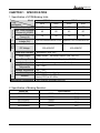
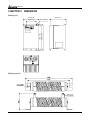
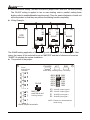
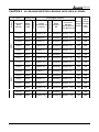
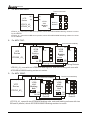
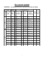
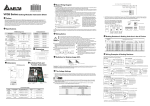
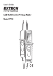
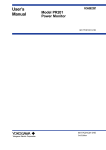
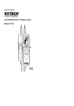
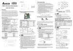
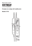
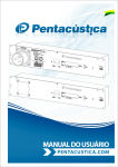
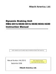
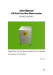
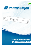
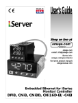
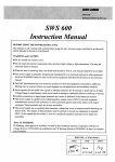
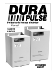
VFDB Series
Preface
Congratulations on your purchase of DELTA’s braking module. VFDB braking units are
applied to absorb the motor regeneration energy when the three phase induction motor stops
by deceleration. With VFDB braking unit, the regeneration energy is dissipated by braking
resistors. To avoid mechanical or human injury, please refer to this user manual before wiring.
VFDB braking units are suitable for DELTA AC Motor Drives VFD Series 230V/460V. VFDB
braking units need to be used in conjunction with BR series braking resistors to provide the
optimum braking characteristics.
VFDB braking units (2015, 2022, 4030 and 4045) are approved by Underwriters Laboratories,
Inc. (UL) and Canadian Underwriters Laboratories (cUL)
DELTA ELECTRONICS, INC. ALL RIGHTS RESERVED
VFDB Series
DELTA ELECTRONICS, INC. ALL RIGHTS RESERVED
VFDB Series
Chapter 1 Specification.................................................................................. 1
Chapter 2 Dimension ..................................................................................... 2
Chapter 3 Individual Parts and Function Explanation .................................... 3
Chapter 4 Basic Wiring Diagram.................................................................... 4
Chapter 5 Wiring Notice................................................................................. 5
Chapter 6 Definition for Braking Usage ED ................................................... 6
Chapter 7 Setting and Regulation.................................................................. 7
Chapter 8 Summary for Braking Units and Braking Resistors ....................... 9
Chapter 9 Wiring Examples of Braking Resistors .......................................... 10
DELTA ELECTRONICS, INC. ALL RIGHTS RESERVED
VFDB Series
DELTA ELECTRONICS, INC. ALL RIGHTS RESERVED
VFDB Series
CHAPTER 1 SPECIFICATION
1. Specification of VFDB Braking Units
Usage Environment
Protection
Input
Rating
Output Rating
Model
230V Series
460V Series
VFDB2015
2022
4030
4045
Specification
Max. Motor Capacity (KW)
15
22
30
45
Max. Peak Discharge
40
60
40
60
Current (A) 10%ED
Continuous Discharge
15
20
15
18
Current (A)
Braking Start-up
330/345/360/380/400/415±3V 660/690/720/760/800/830±6V
Voltage (DC)
DC Voltage
Heat Sink Overheat
Alarm Output
Power Charge Display
Installation Location
Operating
Temperature
Storage Temperature
Humidity
Vibration
Mechanical Configuration
200~400VDC
400~800VDC
Temperature over +95℃
Relay contact 5A120VAC/28VDC (RA, RB, RC)
Blackout until bus (+~-) voltage below 50VDC
Indoor (no corrosive gases, metallic dust)
-10℃~+50℃
-20℃~+60℃
90%R.H., Non-condensing
9.8m/s2 (1G) under 20Hz
2m/s2 (0.2G) at 20~50Hz
Wall-mounted enclosed type IP50
2. Specification of Braking Resistors
Model no.
BR1K5W005
BR1K2W6P8
BR1K2W008
BR1K5W040
BR1K0W050
DELTA ELECTRONICS, INC. ALL RIGHTS RESERVED
Specification
1500W
1200W
1200W
1500W
1000W
1
5.0Ω
6.8Ω
8.0Ω
40Ω
50Ω
VFDB Series
CHAPTER 2 DIMENSION
Braking unit
121.0 [4.76]
80.0 [3.15]
ERR.
RED
200.0 [7.87]
ACT.
YELLOW
189.5 [7.46]
CHARGE
GREEN
130.0 [5.12]
R3.3 [R0.13]
Braking resistor
2
DELTA ELECTRONICS, INC. ALL RIGHTS RESERVED
VFDB Series
CHAPTER 3 INDIVIDUAL PARTS AND FUNCTION EXPLANATION
Terminal Wire Gauge
Circuit
Terminal
Mark
Wire Gauge
Power Input Circuit
+(P), -(N)
10~12AWG/3.5~5.5mm2
M4 Screw 18 KG-CM
Braking Resistor
B1, B2
10~12AWG/3.5~5.5mm2
M4 Screw 18 KG-CM
SLAVE and Fault
Circuit
AWG/mm2
M1, M2
S1, S2
RA, RB, RC
20~18AWG/0.25~0.75mm2
M1, M2, S1, S2 with shielded wires
DELTA ELECTRONICS, INC. ALL RIGHTS RESERVED
3
Terminal
Torque
M2 Screw 4 KG-CM
VFDB Series
CHAPTER 4
BASIC WIRING DIAGRAM
NFB
MC
R/L1
R/L1
U/T1
S/L2
S/L2
V/T2
IM
T/L3
T/L3
W/T3
MOTOR
O.L.
MC
Thermal
SA
Overload
Surge
Relay
Absorber
VFD + ( P )
Series
-( N)
E.F
DCM
+(P )
B1
- ( N ) VFDB
Braking
RA
Unit
B2
RC
Thermal Overload
Relay
O.L.
BR
Braking Resistor
Note1: When AC drive uses with DC reactor, please refer to wiring diagram in AC drive user
manual for the wiring of terminal +(P) of Braking unit.
Note2: Do NOT wire terminal -(N) to neutral point of power system.
Operation Explanation:
1. For safety consideration, install an overload relay between the braking unit and the
braking resistor. In conjunction with the magnetic contactor (MC) prior to the drive, it can
perform complete protection against abnormality.
2. The purpose of installing the thermal overload relay is to protect the braking resistor from
damage due to frequent braking, or due to braking unit keeping operating resulted from
unusual high input voltage. Under such circumstance, just turn off the power to avoid
damaging the braking resistor.
3. Please refer to chapter 3 for the specification of the thermal overload relay.
4. The alarm output terminals (RC, RA, BB) of the braking unit will be activated when the
temperature of the heat sink exceeds 95℃. It means that the temperature of the
installation environment may exceed 50℃, or the braking %ED may exceed 10%ED.
With this kind of alarm, please install a fan to force air-cooling or reduce the environment
temperature. If the condition not due to the temperature, the control circuit or the
temperature sensor may have been damaged. At this time, please send the braking unit
back to the manufacturer or agency for repair.
5. The AC Motor Drive and braking unit will be electrified at the same time while turning on
the NFB (No-fuse breaker). For the operation/stop method of the motor, please refer to
the user manual of the AC Motor Drives VFD Series. The braking unit will detect the inner
DC voltage of the AC motor drive when it stops the motor by deceleration. The extra
regeneration will be dissipated away rapidly by the braking resistor in the form of heat. It
can ensure the stable deceleration characteristic.
4
DELTA ELECTRONICS, INC. ALL RIGHTS RESERVED
VFDB Series
CHAPTER 5
WIRING NOTICE
Do not proceed with wiring while power is applied to the circuit.
!
1.
!
2. The wiring gauge and distance must comply with the electrical code.
!
3. The +(P), -(N) terminals of the AC motor drive (VFD Series), connected to the
braking unit (VFDB), must be confirmed for correct polarity lest the drive and the
braking unit be damaged when power on.
When the braking unit performs braking, the wires connected to +(P), -(N), B1 and
B2 would generate a powerful electromagnetic field for a moment due to high current
passing through. These wires should be wired separately from other low voltage
control circuits lest they make interference or mis-operation.
!
4.
!
5. Wiring distance
VFD series
11~22kW
Max 10M
230/460V
AC Motor Drive
!
!
!
!
!
VFDB
2015
2022
4030
4045
Braking Unit
Max 5M
BR
Braking Resistor
6. Inflammable solids, gases or liquids must be avoided at the location where the
braking resistor is installed. The braking resistor had better be installed in
individual metallic box with forced air-cooling.
7. Connect the ground terminal to the Earth Ground. The ground lead must be at least
the same gauge wire as leads +(P), -(N).
8. Please install the braking resistor with forced air-cooling or the equivalent when
frequent deceleration braking is performed (over 10%ED).
9. To avoid personal injury, do not connect/disconnect wires or regulate the
setting of the braking unit while power on. Do not touch the terminals of
related wiring and any component on PCB lest users be damaged by extreme
dangerous DC high voltage.
10. The ring terminals are suggested to be used for main circuit wiring. Make sure the
terminals are fastened before power on.
DELTA ELECTRONICS, INC. ALL RIGHTS RESERVED
5
VFDB Series
CHAPTER 6 DEFINITION FOR BRAKING USAGE ED%
100%
Braking Time
T1
ED% = T1/T0x100(%)
T0
Cycle Time
Explanation:
The definition of the barking usage ED(%) is for assurance of enough time
for the braking unit and braking resistor to dissipate away heat generated by
braking. When the braking resistor heats up, the resistance would increase with
temperature, and braking torque would decrease accordingly.
6
DELTA ELECTRONICS, INC. ALL RIGHTS RESERVED
VFDB Series
CHAPTER 7
SETTING AND REGULATION
1. Regulation of power voltage: the power source of the braking unit is DC voltage from +(P),
-(N) terminals of the AC motor drive. It is very important to set the power voltage of the
braking unit based on the input power of the AC motor drive before operation. The setting
has a great influence on the potential of the operation voltage for the braking unit. Please
refer to the table below.
Table 1: The Selection of Power Voltage and Operation Potential of PN DC Voltage
230V Model Braking Start-up voltage 460V Model Braking Start-up voltage
AC Power
DC Bus (+(P), -(N))
AC Power
DC Bus (+(P), -(N))
Voltage
Voltage
Voltage
Voltage
190Vac
330Vdc
380Vac
660Vdc
200Vac
345Vdc
400Vac
690Vdc
210Vac
360Vdc
415Vac
720Vdc
220Vac
380Vdc
440Vac
760Vdc
230Vac
400Vdc
460Vac
800Vdc
240Vac
415Vdc
480Vac
830Vdc
Input Power With Tolerance ±10%
CHARGE
ACT
ERR
Power lamp Braking lamp Fault lamp
Input Voltage Setting
480V
460V
440V
415V
400V
380V
240V
230V
220V
210V
200V
190V
For VFDB-4030/4045 Series
Factory setting: 460V
For VFDB-2015/2022 Series
Factory setting: 230V
Note: A. Before regulating the power voltage, make sure the power has been turned off.
B. Please set power voltage as the possible highest voltage for unstable power system.
Take 380VAC power system for example. If the voltage may be up to 410Vac,
415VAC should be regulated.
C. For DELTA’s AC motor drive VFD Series, please set parameter (Over Voltage Stall
Prevention ) as “close” to disable over-voltage stall prevention, to ensure stable
deceleration characteristic.
DELTA ELECTRONICS, INC. ALL RIGHTS RESERVED
7
VFDB Series
2. MASTER/SLAVE setting: The MASTER/SLAVE jumper is set “MASTER” as factory setting.
The “SLAVE” setting is applied to two or more braking units in parallel, making these
braking units be enabled/disabled synchronously. Then the power dissipation of each unit
will be equivalent so that they can perform the braking function completely.
Wiring Example:
+(P )
-( N)
+(P )
-( N)
+(P )
M1
M2
VFD
Series
-( N)
M1
M2
S1
S2
+(P )
-( N)
S1
S2
SLAVE
SLAVE
MASTER
B1
O.L.
B2
B1
BR
B2
BR
O.L.
B1
O.L.
B2
BR
The SLAVE braking application of three braking units is shown as the above diagram. After
wiring, the jumper of first unit shall be set as “MASTER” and that of others must be set as
“SLAVE” to complete the system installation.
The position of the jumper:
ACT
CHARGE
Slave
output/input
Terminal
ERR
Power lamp Braking lamp Fault lamp
M2 M1 S2
480V
460V
440V
415V
400V
380V
SLAVE
S1
240V
230V
220V
210V
200V
190V
RC RB RA
M1:SLAVE output signal +
M2:SLAVE output signal S1:SLAVE input signal +
S2:SLAVE input signal -
MASTER
MASTER/SLAVE
Setting Jumper
NOTE: Please use shielded wires
while wiring.
Alarm output terminals
8
DELTA ELECTRONICS, INC. ALL RIGHTS RESERVED
VFDB Series
460V
230V
Braking Unit
Discharged Resistor
Resistor
Specification for
a Resistor
Numbers
Voltage
AC Drive
ALL BRAKING RESISTORS & BRAKING UNITS USE IN AC DRIVES
Numbers
CHAPTER 8
Equivalent
Resistors
Specification for
Each Braking Unit
Applicable
Motor
KW(HP)
Model
NumberVFDB
11(15)
2015
1 1200W 6.8Ω 2 1K2W6P8 2400W 13.6Ω
125
20A
15(20)
2015
1 1500W 5Ω
2 1K5W005 3000W 10Ω
125
30A
18.5(25)
2022
1 1200W 8Ω
4 1K2W008 4800W 8Ω
125
35A
22(30)
2022
1 1200W 6.8Ω 4 1K2W6P8 4800W 6.8Ω
125
40A
30(40)
2015
2 1500W 5Ω
4 1K5W005 3000W 10Ω
125
30A
37(50)
2015
2 1500W 5Ω
4 1K5W005 3000W 10Ω
100
30A
45(60)
2022
2 1200W 6.8Ω 8 1K2W6P8 4800W 6.8Ω
120
30A
11(15)
4030
1 1000W 50Ω
1 1K0W050 1000W 50Ω
135
10A
15(20)
4030
1 1500W 40Ω
1 1K5W040 1500W 40Ω
125
15A
18.5(25)
4030
1 1200W 8Ω
4 1K2W008 4800W 32Ω
125
15A
22(30)
4030
1 1200W 6.8Ω 4 1K2W6P8 4800W 27.2Ω
125
20A
30(40)
4030
1 1500W 5Ω
4 1K5W005 6000W 20Ω
125
30A
37(50)
4045
1 1200W 8Ω
8 1K2W008 9600W 16Ω
125
40A
45(60)
4045
1 1200W 6.8Ω 8 1K2W6P8 9600W 13.6Ω
125
50A
55(75)
4030
2 1500W 5Ω
125
30A
75(100)
4045
2 1200W 6.8Ω 16 1K2W6P8 9600W 13.6Ω
125
50A
DELTA ELECTRONICS, INC. ALL RIGHTS RESERVED
Model
NumberBR
Typical
Braking Thermal
Torque Overload
10%ED Relay
Value
8 1K5W005 6000W 20Ω
9
VFDB Series
CHAPTER 9
WIRING EXAMPLES OF BRAKING RESISTORS
NOTE: Before wiring, please notice equivalent resistors value shown in the column
“Equivalent resistors specification for each braking unit” in the previous page
to avoid damage.
1. For 230V 15HP/20HP:
B1
+(P )
+( P )
VFD
Series - ( N )
Thermal Overload
Relay
O.L.
-( N)
VFDB
2015
Braking
Unit
VFD110_23_
VFD150_23_
Braking
Resistor
B2
VFD110_23_ uses with 2PCS BR1K2W6P8 braking resistors in series
VFD150_23_ uses with 2PCS BR1K5W005 braking resistors in series
2. For 230V 25HP/30HP :
Thermal Overload
Relay
B1
+ (P )
VFD
Series
-( N)
VFD185_23_
VFD220_23_
+ (P )
O.L.
VFDB
- ( N ) 2022
Braking
Unit
Braking
Resistor
B2
VFD185_23_ uses with two BR sets in parallel, which 2PCS BR1K2W008 braking resistors
in series for each BR set.
VFD220_23_ uses with two BR sets in parallel, which 2PCS BR1K2W6P8 braking resistors
in series for each BR set.
3. For 230V 40HP/50HP:
Thermal Overload Relay
Thermal Overload Relay
+(P ) - (N)
VFD
Series
VFD300_23_
VFD370_23_
+ ( P ) - ( N ) B1
+ ( P ) - ( N ) B1
VFDB
2015
Braking
Unit
O.L.
VFDB
2015
Braking
Unit
O.L.
SLAVE
MASTER
B2
M1 M2
Braking
Resistor
B2
S1 S2
Braking
Resistor
VFD300_23_ / VFD370_23_ use with two VFDB2015 braking units, and each braking
unit uses with 2PCS BR1K5W005 braking resistors in series.
10
DELTA ELECTRONICS, INC. ALL RIGHTS RESERVED
VFDB Series
4. For 230V 60HP:
Thermal Overload Relay
Thermal Overload Relay
+ (P ) - (N )
+ ( P ) - ( N ) B1
+ ( P ) - ( N ) B1
VFDB
2022
Braking
Unit
VFD
Series
VFD450_23_
VFDB
2022
Braking
Unit
O.L.
O.L.
SLAVE
MASTER
B2
M1 M2
B2
S1 S2
Braking
Resistor
Braking
Resistor
VFD450_23_ uses with two VFDB2022 braking units, and each braking unit uses with two
BR sets in parallel, which 2PCS BR1K2W6P8 braking resistors in series.
5. For 460V 15HP/20HP:
B1
+(P )
VFD
Series
- (N)
+(P )
-( N)
Thermal Overload
Relay
O.L.
VFDB
4030
Braking
Unit
VFD110_43_
VFD150_43_
Braking
Resistor
B2
VFD110_43_ uses with 1PCS BR1K0W050 braking resistor
VFD150_43_ uses with 1PCS BR1K5W040 braking resistor
6. For 460V 25HP/30HP/40HP:
B1
+(P )
VFD
Series
-( N)
VFD185_43_
VFD220_43_
VFD300_43_
+(P )
Thermal Overload
Relay
O.L.
VFDB
- ( N ) 4030
Braking
Unit
Braking
Unit
B2
VFD185_43_ uses with 4PCS BR1K2W008 braking resistors in series
VFD220_43_ uses with 4PCS BR1K2W6P8 braking resistors in series
VFD300_43_ uses with 4PCS BR1K5W005 braking resistors in series
DELTA ELECTRONICS, INC. ALL RIGHTS RESERVED
11
VFDB Series
7.
For 460V 50HP/60HP:
B1
VFD
Series
+(P )
+ (P )
- (N )
-(N)
O.L.
VFDB
4045
Braking
Unit
VFD370_43_
VFD450_43_
Thermal Overload
Relay
Braking
Resistor
B2
VFD370_43_ uses with two BR sets in parallel, which 4PCS BR1K2W008 braking resistors in series
for each BR set.
VFD450_43_ uses with two BR sets in parallel, which 4PCS BR1K2W6P8 braking resistors in series
for each BR set.
8.
For 460V 75HP:
Thermal Overload Relay
Thermal Overload Relay
+ (P ) - (N )
VFD
Series
VFD550_43_
+ (P ) - (N )
+ ( P ) - ( N ) B1
VFDB
4030
Braking
Unit
B1
VFDB
4030
Braking
Unit
O.L.
O.L.
SLAVE
MASTER
B2
M1 M2
B2
S1 S2
Braking Resistor
Braking Resistor
VFD550_43_ uses with two VFDB4030 braking units, and each braking unit uses with
4PCS BR1K5W005 braking resistors in series.
9.
For 460V 100HP:
Thermal Overload Relay
Thermal Overload Relay
+(P ) - (N)
VFD
Series
VFD750_43_
+ ( P ) - ( N ) B1
+ ( P ) - ( N ) B1
VFDB
4045
Braking
Unit
O.L.
VFDB
4045
Braking
Unit
O.L.
SLAVE
MASTER
B2
M1 M2
Braking
Resistor
B2
S1 S2
Braking
Resistor
VFD750_43_ uses with two VFDB4045 braking units, and each braking unit uses with two
BR sets in parallel, which 4PCS BR1K2W6P8 braking resistors in series.
12
DELTA ELECTRONICS, INC. ALL RIGHTS RESERVED
Document Update
460V
230V
Braking Unit
Discharged Resistor
Resistor
Specification for
a Resistor
Numbers
Voltage
AC Drive
ALL BRAKING RESISTORS & BRAKING UNITS USE IN AC DRIVES
Numbers
CHAPTER 8
Model
NumberBR
Equivalent
Resistors
Specification for
Each Braking Unit
Typical
Braking Thermal
Torque Overload
10%ED Relay
Value
Applicable
Motor
KW(HP)
Model
NumberVFDB
11(15)
2015
1 1200W 6.8Ω 2 1K2W6P8 2400W 13.6Ω
125
20A
15(20)
2015
1 1500W 5Ω
2 1K5W005 3000W 10Ω
125
30A
18.5(25)
2022
1 1200W 8Ω
4 1K2W008 4800W 8Ω
125
35A
22(30)
2022
1 1200W 6.8Ω 4 1K2W6P8 4800W 6.8Ω
125
40A
30(40)
2015
2 1500W 5Ω
4 1K5W005 3000W 10Ω
125
30A
37(50)
2015
2 1500W 5Ω
4 1K5W005 3000W 10Ω
100
30A
45(60)
2022
2 1200W 6.8Ω 8 1K2W6P8 4800W 6.8Ω
120
30A
11(15)
4030
1 1000W 50Ω
1 1K0W050 1000W 50Ω
135
10A
15(20)
4030
1 1500W 40Ω
1 1K5W040 1500W 40Ω
125
15A
18.5(25)
4030
1 1200W 8Ω
4 1K2W008 4800W 32Ω
125
15A
22(30)
4030
1 1200W 6.8Ω 4 1K2W6P8 4800W 27.2Ω
125
20A
30(40)
4030
1 1500W 5Ω
4 1K5W005 6000W 20Ω
125
30A
37(50)
4045
1 1200W 8Ω
8 1K2W008 9600W 16Ω
125
40A
45(60)
4045
1 1200W 6.8Ω 8 1K2W6P8 9600W 13.6Ω
125
50A
55(75)
4030
2 1500W 5Ω
125
30A
75(100)
4045
2 1200W 6.8Ω 16 1K2W6P8 9600W 13.6Ω
125
50A
8 1K5W005 6000W 20Ω
1
CHAPTER 9
WIRING EXAMPLES OF BRAKING RESISTORS
NOTE: Before wiring, please notice equivalent resistors value shown in the column
“Equivalent resistors specification for each braking unit” in the previous page
to avoid damage.
1. For 230V 15HP/20HP:
B1
+(P )
+( P )
VFD
Series - ( N )
Thermal Overload
Relay
O.L.
-( N)
VFDB
2015
Braking
Unit
VFD110_23_
VFD150_23_
Braking
Resistor
B2
VFD110_23_ uses with 2PCS BR1K2W6P8 braking resistors in series
VFD150_23_ uses with 2PCS BR1K5W005 braking resistors in series
2. For 230V 25HP/30HP :
Thermal Overload
Relay
B1
+ (P )
VFD
Series
-( N)
VFD185_23_
VFD220_23_
+ (P )
O.L.
VFDB
- ( N ) 2022
Braking
Unit
Braking
Resistor
B2
VFD185_23_ uses with two BR sets in parallel, which 2PCS BR1K2W008 braking resistors
in series for each BR set.
VFD220_23_ uses with two BR sets in parallel, which 2PCS BR1K2W6P8 braking resistors
in series for each BR set.
3. For 230V 40HP/50HP:
Thermal Overload Relay
Thermal Overload Relay
+(P ) - (N)
VFD
Series
VFD300_23_
VFD370_23_
+ ( P ) - ( N ) B1
+ ( P ) - ( N ) B1
VFDB
2015
Braking
Unit
O.L.
VFDB
2015
Braking
Unit
O.L.
SLAVE
MASTER
B2
M1 M2
Braking
Resistor
B2
S1 S2
Braking
Resistor
VFD300_23_ / VFD370_23_ use with two VFDB2015 braking units, and each braking
unit uses with 2PCS BR1K5W005 braking resistors in series.
2
4. For 230V 60HP:
Thermal Overload Relay
Thermal Overload Relay
+ (P ) - (N )
+ ( P ) - ( N ) B1
+ ( P ) - ( N ) B1
VFDB
2022
Braking
Unit
VFD
Series
VFD450_23_
VFDB
2022
Braking
Unit
O.L.
O.L.
SLAVE
MASTER
B2
M1 M2
B2
S1 S2
Braking
Resistor
Braking
Resistor
VFD450_23_ uses with two VFDB2022 braking units, and each braking unit uses with two
BR sets in parallel, which 2PCS BR1K2W6P8 braking resistors in series.
5. For 460V 15HP/20HP:
B1
+(P )
VFD
Series
- (N)
+(P )
-( N)
Thermal Overload
Relay
O.L.
VFDB
4030
Braking
Unit
VFD110_43_
VFD150_43_
Braking
Resistor
B2
VFD110_43_ uses with 1PCS BR1K0W050 braking resistor
VFD150_43_ uses with 1PCS BR1K5W040 braking resistor
6. For 460V 25HP/30HP/40HP:
B1
+(P )
VFD
Series
-( N)
VFD185_43_
VFD220_43_
VFD300_43_
+(P )
Thermal Overload
Relay
O.L.
VFDB
- ( N ) 4030
Braking
Unit
Braking
Unit
B2
VFD185_43_ uses with 4PCS BR1K2W008 braking resistors in series
VFD220_43_ uses with 4PCS BR1K2W6P8 braking resistors in series
VFD300_43_ uses with 4PCS BR1K5W005 braking resistors in series
3
7.
For 460V 50HP/60HP:
B1
VFD
Series
+(P )
+(P )
-(N)
-(N)
O.L.
VFDB
4045
Braking
Unit
VFD370_43_
VFD450_43_
Thermal Overload
Relay
Braking
Resistor
B2
VFD370_43_ uses with two BR sets in parallel, which 4PCS BR1K2W008 braking resistors in series
for each BR set.
VFD450_43_ uses with two BR sets in parallel, which 4PCS BR1K2W6P8 braking resistors in series
for each BR set.
8.
For 460V 75HP:
Thermal Overload Relay
Thermal Overload Relay
+(P ) - (N)
VFD
Series
VFD550_43_
+(P ) - (N)
+ ( P ) - ( N ) B1
VFDB
4030
Braking
Unit
B1
VFDB
4030
Braking
Unit
O.L.
O.L.
SLAVE
MASTER
B2
M1 M2
B2
S1 S2
Braking Resistor
Braking Resistor
VFD550_43_ uses with two VFDB4030 braking units, and each braking unit uses with
4PCS BR1K5W005 braking resistors in series.
9.
For 460V 100HP:
Thermal Overload Relay
Thermal Overload Relay
+(P ) - (N)
VFD
Series
VFD750_43_
+ ( P ) - ( N ) B1
+ ( P ) - ( N ) B1
VFDB
4045
Braking
Unit
O.L.
VFDB
4045
Braking
Unit
O.L.
SLAVE
MASTER
B2
M1 M2
Braking
Resistor
B2
S1 S2
Braking
Resistor
VFD750_43_ uses with two VFDB4045 braking units, and each braking unit uses with two
BR sets in parallel, which 4PCS BR1K2W6P8 braking resistors in series.
4