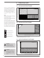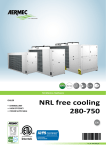
1
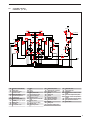
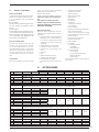
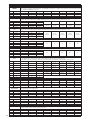
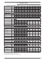
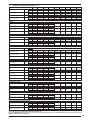
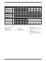
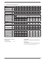
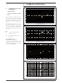
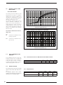
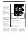
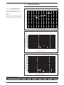
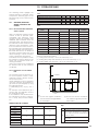
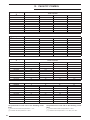
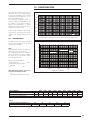
coo
ling
scroll
axial
heat
GR3
CHILLERS AND AIR WATER HEAT PUMPS - TECHNICAL MANUAL
COOLER AIR | WATER
• INDOOR UNIT STANDARD EFFICIENT
• FOR OUTDOOR INSTALLATIONS
• STANDARD VERSIONS RUNNING
LOWNOISE
NRL 280-700
standard
EN
INRLTY.05_13_5172705_01
Dear Customer,
Thank you for choosing an AERMEC product. This product is the result of many years of experience and indepth engineering research, and it is built using top quality materials and advanced technologies.
In addition, the CE mark guarantees that our appliances fully comply with the requirements of the
European Machinery Directive in terms of safety. We constantly monitor the quality level of our products,
and as a result AERMEC products are synonymous with Safety, Quality, and Reliability.
Product data may be subject to modifications deemed necessary for improving the product without
the obligation to give prior notice.
Thank you again.
AERMEC S.p.A
AERMEC S.p.A. reserves the right at any moment to make any modifications considered necessary to improve our products and is
not obliged to add these modifications to machines that have already been manufactured, delivered or are under construction.
INDEX
1.1.
USE IN COMPLIANCE WITH DESTINATION............................3
1.2.
PRESERVATION OF THE DOCUMENTATION.........................3
1.
NOTES REGARDING THE DOCUMENTATION.......................3
2.
FUNDAMENTAL SAFETY REGULATIONS.................................3
3.
PRODUCT IDENTIFICATION....................................................3
4.1.
MODELS AVAILABLE...............................................................4
4.2.
VERSIONS AVAILABLE............................................................4
4.3.SILENCED...................................................................................
MOTORCONDENSERS (CL)...................................................4
4.
DESCRIPTION OF THE UNIT.....................................................4
4.4.CONFIGURATOR....................................................................5
5.1.
NRL 0280-0300-0330-0350.....................................................6
5.
DESCRIPTION OF THE COMPONENTS..................................6
5.2.
NRL 0500-0550-0600-0650-0700...........................................7
5.3.
COOLING CIRCUITS, HYDRAULIC ( ° - L )............................8
5.4.
COOLING CIRCUITS,HYDRAULIC ( H - Hl ).........................9
5.5.
COOLING CIRCUIT...............................................................10
5.6.
FRAME AND FANS................................................................10
5.7.
HYDRAULIC COMPONENTS................................................10
5.8.
CONTROL AND SAFETYCOMPONENTS .............................10
5.9.
ELECTRIC COMPONENTS....................................................11
6.ACCESSORIES.......................................................................11
7.1.
TECHNICAL DATA FOR VERSIONS ( ° - L )..........................13
7.
TECHNICAL DATA.................................................................13
7.2.
TECHNICAL DATA FOR VERSIONS( H - HL )........................15
7.3.
TECHNICAL DATA FOR VERSIONS (c)................................17
8.
OPERATIONAL LIMITS...........................................................18
8.1.
COOLING MODE FUNCTIONING ......................................18
8.2.
HEATING MODE FUNCTIONING..........................................18
8.3.
MOTORCONDENSING FUNCTIONING...............................18
9.1.
COOLING CAPACITY AND INPUT POWER .......................19
9.
CORRECTIVE COEFFICIENTS...............................................19
9.2.
HEATING CAPACITY AND INPUT POWER...........................20
9.3.
FOR ∆t DIFFERENT TO THE
NOMINAL........................20
9.4.
DEPOSIT FACTORS................................................................20
10.1. HOW TO INTERPRET GLYCOL CURVES...............................21
10.
ETHYLENE GLYCOL SOLUTION............................................21
11.1. TOTAL PRESSURE DROPS......................................................22
11.
PRESSURE DROPS..................................................................22
12.1. MINIMUM/MAXIMUM WATER ................................................
CONTENT IN THE SYSTEM ....................................................23
12.
STORAGE TANK.....................................................................23
13.
CAPACITY CONTROL...........................................................24
14.1. PRESSURE DROPS..................................................................25
14.DESUPERHEATER...................................................................25
15.1.
NRL (T)...................................................................................26
15.2. PRESSURE DROPS..................................................................26
15.
TOTAL RECOVERY................................................................26
16.dimensionEMENT COOLING LINES version (c)............27
17.
18.
SOUND DATA........................................................................28
CALIBRATION OF CONTROL AND SAFETY PARAMETERS.29
For the installation of the appliance, please comply with the safety rules and regulations contained in these instructions
Moving parts hazard
Danger: Disconnect voltage
High temperature hazard
Generic danger
Voltage hazard
i
Useful information and notices
1
AERMEC S.p.A.
37040 Bevilacqua (VR) Italy – Via Roma, 996
Tel. (+39) 0442 633111
Telefax 0442 93730 – (+39) 0442 93566
www.aermec.com - [email protected]
NRL
SERIAL NUMBER
EC DECLARATION OF CONFORMITY
We, the undersigned, hereby declare under our own responsibility that
the assembly in question, defined as follows:
NAME
NRL
TYPE
AIR/WATER HEAT PUMPCHILLER
MODEL
To which this declaration refers, complies with the following harmonised standards:
CEI EN 60335-2-40
Safety standard regarding electrical heat pumps, air conditioners and
dehumidifiers
CEI EN 61000-6-1
CEI EN 61000-6-3
Immunity and electromagnetic emissions for residential environments
CEI EN 61000-6-2
CEI EN 61000-6-4
Immunity and electromagnetic emissions for industrial environments
EN378
Refrigerating systems and heat pumps - Safety and environmental
requirements
UNI EN 12735
UNI EN 14276
Seamless, round copper tubes for air conditioning and refrigeration
Pressure equipment for cooling systems and heat pumps
Therefore complying with the essential requirements of the following directives:
- LVD Directive: 2006/95/CE
- Electromagnetic compatibility Directive2004/108/CE
- Machinery Directive 98/37/CE
- PED Directive regarding pressurised devices 97/23/CE
The product, in agreement with Directive 97/23/CE, satisfies the Total quality Guarantee procedure (form H)
with certificate n.06/270-QT3664 Rev.3 issued by the notified body n.1131 CEC via Pisacane 46 Legnano (MI) Italy
Bevilacqua
15/01/2008
Marketing Manager
Signature
2
1. NOTES REGARDING THE DOCUMENTATION
1.1.
SE IN COMPLIANCE WITH
U
DESTINATION
AERMEC units are constructed according to the recognised technical
standards and safety regulations.
These appliances are designed and
built for heating and hot water production and also for cooling and
must be used in compatibility with
their technical features. In spite of this,
dangers to the user or third parties
may arise, as well as damage to the
appliance and other objects, in the
event of improper use and use that
is not in compliance with that envisioned.
Any use not expressly indicated in
this manual is not permitted. Consequently AERMEC will not assume any
responsibility for damage that may
occur due to failure to comply with
these instructions.
1.2.
RESERVATION OF THE
P
DOCUMENTATION
The installation instructions, along
with all the related documentation,
must be given to the user of the system, who assumes the responsibility of
keeping the instructions so that they
are always at hand in case of need.
READ THIS DOCUMENT CAREFULLY, the
appliance must be installed by qualified and suitably prepared staff in
compliance with the national legislation effective in the country of destination.
The appliance must be installed so
that maintenance and/or repairs can
be carried out. The appliance warranty does not cover the costs for ladders, scaffolding, or other elevation
systems that may become necessary
for carrying out servicing under warranty.
The validity of the warranty shall be
void in the event of failure to comply
with the above-mentioned indications.
2. F
UNDAMENTAL SAFETY REGULATIONS
We remind you that the use of products that employ electrical energy
and water requires that a number
of essential safety rules be followed,
such as:
This appliance is not suitable for use
by persons (including children) with
limited physical, sensory, or mental
capacities or those lacking experience or know-how, unless they are
supervised or instructed regarding the use of the appliance by a
person who is responsible for their
safety. Children must always be supervised to ensure they do not play
with the appliance.
It is prohibited to carry out any technical or maintenance operation
before the unit has been disconnected from the electrical mains
by switching off the master switch
of the system and the main power
switch on the control panel.
It is prohibited to modify the safety
or adjustment devices without the
manufacturer’s authorisation and
precise instructions
It is prohibited to pull, disconnect, or
twist the electrical cables coming
from the unit even if disconnected
from the electrical mains.
It is prohibited to leave containers
and flammable substances near to
the unit.
It is prohibited to touch the appliance when you are barefoot and
with parts of the body that are wet
or damp.
It is prohibited to open the access hatches to the internal parts
of the appliance without first having switched off the system master
switch.
It is prohibited to disperse or abandon the packing materials and
they must be kept out of the reach
of children, as they are a potential
source of danger.
3. PRODUCT IDENTIFICATION
NRL can be identified by means of:
− Packing label that reports the identification data of
the product.
TECHNICAL
PLATE
AE R M E C SP A - via R oma 44
37040 - B evilacqua (V R ) - I T AL I A
M OD.
vers.
P rod. date
IP
Serial no
C A L DO
HE A T
C HA UD
HE I ZUNG
T S(H P /L P )
P t = kW
F R E DDO
COL D
F R OI D
K UHL UNG
P e = kW
In = A
Is = A
C
R E S.E L /E L .HE AT E R
R E S.E L /E -HE I ZUNG
M in.
M ax.
kW
max
=
P f = kW
P e = kW
In = A
Is = A
P S (H P /L P )
bar
R 407C
Kg
I n R x max = A
I tot max = A
PACKING
LABEL
− Technical plate
positioned on the lateral cross-member of the electric box.
NOTE:
Tampering, removal, lack of the identification plate or other does not allow
safe identification of the product and
will make any installation or maintenance operation to be performed difficult.
TECHNICAL
PLATE
AE R M E C SP A - via R oma 44
37040 - B evilacqua (V R ) - I T AL I A
M O D.
vers.
P rod. date
T S(H P /L P )
P t = kW
F R E DDO
COL D
F R OI D
K UHL UNG
P e = kW
In = A
Is = A
C
R E S.E L /E L .HE AT E R
R E S.E L /E -HE I ZUNG
M in.
M ax.
kW
max
=
PACKING
LABEL
IP
Serial no
C A L DO
HE A T
C HA UD
HE I ZUNG
P f = kW
P e = kW
In = A
Is = A
P S (H P /L P )
bar
R 407C
Kg
I n R x max = A
I tot max = A
3
4.
Standards and directives to be followed in the
design and manufacture
of the unit:
−
Safety system:
Machine Directive
2006/42/EC
Low voltage directive
LVD 2006/95/EC
Electromagnetic compatibility directive
EMC 2004/108/EC
Pressure containers directive
PED 97/23/CE EN 378,
UNI EN 14276
Electrical part:
EN 60204-1
Protection rating
IP24
Acoustic part:
SOUND POWER
(EN ISO 9614-2)
SOUND PRESSURE
(EN ISO 3744)
Certifications:
Eurovent
−
−
Refrigerant GAS:
This unit contains fluorinated
greenhouse gases covered by
the Kyoto Protocol.
Maintenance and disposal
operations must be only
carried out by qualified staff.
R410A GWP=1900
The appliances in the NRL series are
units used for the production of cold
water for technological systems. The
heat pump models also allow to produce hot water for heating. They are
made up of two R410A cooling circuits and a unique hydraulic circuit,
which may or may not be supplied
with storage or pumping unit. The
presence of several scroll compressors allows NRL chillers various partialisations of the cooling capacity. The electronic adjustment with
microprocessor controls and manages all components and functioning parameters. An internal memory
records the functioning conditions
when an alarm occurs in order to
show it on the display. The units have
an IP 24 protection rating.
4.1.
−
−
−
−
−
−
−
4
MODELS AVAILABLE
“COOLING ONLY” (° - L)
maximum external temperature accepted 42°C;
temperature water product 18°C;
“HEAT PUMP” (H - HL)
in
cooling mode the operational limits
reach a maximum external air temperature of 42°C;
temperature water product 18°C;
in heating mode the operational
limits reach a maximum external air
temperature of 42°C;
temperature water product 50°C;
NRLH does not envision the following
configurations:
YH (with water produced lower than 4 °C)
HC (motorcondencing heat pump)
4.2.
•
DESCRIPTION OF THE UNIT
VERSIONS AVAILABLE
RECUPERATORI DI CALORE:
HEAT RECUPERATORS:
with desuperheater inserted
in series (D).
−
ATTENTION:
In heat pump models the desuperheater must be shut-off in heat pump
mode, or the warranty will be come
void.
•
Total heat recovery (T)
With plate heat exchanger
inserted in parallel with the coils.
−
−
Both of these versions (D - T) have:
Hot gas by-pass device upstream
from the evaporator.
Water filter before the recovery heat
exchanger.
−
Units with Desuperheater (D)
or Total Recovery (T) do not envision the
following versions:
− YD
− YT
− XT (only for temperature under 4°C)
− XD (only for temperature under 4°C)
4.3.
SILENCED
MOTORCONDENSERS (CL)
The NRL-C motorcondensers do not envision the following versions:
−
−
−
HC (motorcondencing heat pump)
TC (motorcondensing with total recovery)
DC motorcondensing with storage
tank.
Mechanical thermostatic valve
− version Y: it is the version that allows
to produce cooled water below the
standard value of +4 °C to a minimum of -6 °C. Contact the head office for lower values.
4.4.
CONFIGURATOR
1,2,3
4,5,6,7
8
9
10
11
12
13
14
15
16,17
NRL
028
°
°
°
°
°
°
°
°
00
Campo
1, 2 ,3
Code
4, 5, 6, 7 Size
NRL
0280 - 0300 - 0330 - 0350 - 0500 - 0550 - 0600 - 0650 - 0700
8
Thermostatic valve
°
Standard mechanical thermostatic valve
Y
Low water temperature mechanical thermostatic valve (to -6°C)
X
Electronic thermostatic valve also for low water temperature (to -6°C)
9
Model
°
C
H
10
Heat recovery
°
Without recuperators
D
Desuperheater
T
Total recovery
11
Version
°
L
Standard Cooling Only
Compact silenced
12
Coils
°
R
S
V
In aluminium
In copper
Tinned copper
Painted
13
Fans
°
M
Standard
Larger
14
Power supply
°
400V-3N-50Hz with magnet circuit breakers
1
220V-3-50Hz with magnet circuit breakers
15, 16
Storage tank
00
Without hydronic storage tank
01
Low static pressure storage tank and single pump
02
Low static pressure storage tank and reserve pump
03
High static pressure storage tank and single pump
04
High static pressure storage tank and reserve pump
05
Storage tank with holes for int. res. low static pressure and single pump
06
Storage tank with holes for int. res. low static pressure and reserve pump
07
Storage tank with holes for int. res. high static pressure and single pump
08
Storage tank with holes for int. res. high static pressure and reserve pump
09
Double water ring
10
Double water ring with integrated resistance
P1
Without storage tank with low static pressure
P2
Without storage tank with low static pressure pump and reserve pump
P3
Without storage tank with high static pressure
P4
Without storage tank with high static pressure pump and reserve pump
Cooling Only
Motorcondensing
Heat Pump
[1] Available only for 0280, 0300, 0330, 0600, 0650.
5
5. DESCRIPTION OF THE COMPONENTS
5.1.
NRL 0280-0300-0330-0350
9
10
8
19
18
15
16
17
7
11
6
12
14
4
3
5
20
2
1
KEY:
6
1
2
Plate heat exchanger
Storage tank
11
12
Compressors
Storage tank draining
3
4
5
6
7
8
9
10
Expansion vessel
Pumps
Loading unit
Safety valve
Vent valve
Coil
Fans
Electric Control Board
13
14
15
16
17
18
19
20
Desuperheater
Mounted filter
Cycle reversing valves
Liquid storage tank
Thermostatic valves
Dehydrator filter
Liquid separator
Electric resistance
13
NOTE:
The drawings shown are only
an example.
5.2.
NRL 0500-0550-0600-0650-0700
9
10
14
8
13
7
18
16
15
17
6
12
4
3
5
20
11
2
NOTE:
The drawings shown are only
an example.
1
KEY:
1
2
Plate heat exchanger
Storage tank
11
12
Compressors
Storage tank draining
3
4
5
6
7
8
9
10
Expansion vessel
Pumps
Loading unit
Safety valve
Vent valve
Coil
Fans
Electric Control Board
13
14
15
16
17
18
19
20
Desuperheater
Mounted filter
Cycle reversing valves
Liquid storage tank
Thermostatic valves
Dehydrator filter
Liquid separator
Electric resistance
7
5.3.
COOLING CIRCUITS,
HYDRAULIC ( ° - L )
V
V
VSA
BAT
BAT
RU
VSIC
SF
VE
RU
loading
VSIC
GR
RU
AP
FD
FD
VS
VS
IDL
IDL
PP
PP
SA
RU
EQ
TGP
PP
VT
VT
RE
SD
AP
EQ
TGP
RU
P
P
CP
RS
PP
CP
VNR VNR
SIW
BVT
BP
FM
BVT
PP
SC
PP
BP
FL
SUW
QE
QE
FM
VE
--VaS
VSA
TGP
CP
FL
SA
SF
8
Electric Control Board
Water filter
Expansion vessel
Electric cable
Ball valve
Water safety valve
Pressing line gas circuit
breaker
Compressor
Flow switch
Water tank
Venting
V
BAT
RU
FD
VT
SC
PP
TAP
RU
BP
RS
Fan
Coil
Cock
Dehydrator filter
Thermostatic valve
Heat exchanger
Pressure point
High pressure transducer
Cock
Low pressure switch
Drain cock
SD
RE
VNR
P
GR
RU
SD
RE
VNR
P
GR
Anti-freeze probe
300W electric resistance
Non-return valve
Pump
Filling unit
Cock
Anti-freeze probe
Electric resistance
Non-return valve
Pump
Filling unit
VS
IDL
EQ
BVT
SIW
SUW
AP
Solenoid valve
Liquid indicator
Equaliser
Temperature control valve
bulb
Inlet water temperature probe
Outlet water temperature
probe
High pressure pressure switch
5.4.
COOLING CIRCUITS,
HYDRAULIC ( H - Hl )
VSA
V
V
RCS
BAT
BAT
PP
VIC
PP
TAP
AP
VU EQ
VU
TGP
PP
FD
VS
VS
IL
IL
VS
VS
VIC
TGP
PP
VT
VIC
RS
RU
PP
TAP
SEP
AP
P
VSIC
BP
TBP
PP
BVT
VU
FD
VT
VSIC
CP
SD
AL
SEP
loading
GR
RE
EQ VU
BVT
SA
PP
AL
VIC
SF
VE
RCS
VNR
P
VNR
BP
C
VU
VU
VU
C
VU
CP
TBP
PP
SIW
FM
SC
FL
SUW
QE
QE
FM
Electric Control Board
Water filter
VE
--VU
AL
CP
VSA
TGP
Expansion vessel
Electric cable
One-way valve
Liquid storage tank
Compressor
Water safety valve
Pressing line gas circuit
breaker
Water tank
Venting
Load/drain cock
SA
SF
RCS
V
BAT
RU
FD
VT
SC
PP
TAP
Fan
Coil
Cock
Dehydrator filter
Thermostatic valve
Heat exchanger
Pressure point
High pressure transducer
VSIC Safety valve
BP
Low pressure switch
RS
Drain cock
SEP Liquid separator
SD
RE
VNR
P
GR
RU
SD
RE
VNR
P
GR
VIC
Anti-freeze probe
300W electric resistance
Non-return valve
Pump
Filling unit
Cock
Anti-freeze probe
Electric resistance
Non-return valve
Pump
Filling unit
Cycle reversing valve
VS
IDL
EQ
BVT
SIW
SUW
AP
TBP
FL
Solenoid valve
Liquid indicator
Equaliser
Temperature control valve
bulb
Inlet water temperature probe
Outlet water temperature
probe
High pressure pressure switch
Low pressure transducer
Flow switch
9
5.5.
COOLING CIRCUIT
Compressors
Highly efficient hermetic scroll compressors on anti-vibration mounts, activated by
a 2-pole electric motor with internal circuit
breaker protection, supplied as per standard with sump resistance.
The resistance is powered automatically
when the unit stops as long as the unit is live.
Desuperheater (on request only)
Plate type (AISI 316), insulated externally
with closed cell material to reduce heat
loss.
Air-side heat exchanger
High efficiency realised with copper pipes
and aluminium louvers blocked by mechanical expansion of the pipes.
Total recovery (on request only)
Plate type (AISI 316), insulated externally
with closed cell material to reduce heat
loss.
Water-side heat exchanger
Plate type (aisi 316), insulated externally
with closed cell material to reduce heat
loss. Equipped as per standard with the
anti-freeze electric resistance.
5.6.
Liquid separator
(for heat pump only)
Positioned on compressor intake for protection against any return of refrigerant
fluid, flooded start-up and functioning in
the presence of liquids.
Liquid storage tank
(for heat pumps and total recovery only)
Compensates the difference in volume
between louvers coil and plate exchanger, withholding excess liquid.
Dehydrator filter
Mechanical dehydrator filter realised in
ceramics and hygroscopic material, able
to withhold impurities and any traces of
humidity present in the cooling circuit.
Liquid indicator
Used to check the refrigerant gas load
and any presence of humidity in the cooling circuit.
Thermostatic valve
The mechanical valve, with external
equaliser positioned at evaporator outlet,
modulates the flow of gas to the evaporator, depending on the heat load, in order
to ensure a correct level of heating of the
intake gas.
Electronic valve (optional)
Liquid and pressing line cocks
(cooling versions only)
Allows interruption of the refrigerant in the
case of extraordinary maintenance.
Solenoid valve
The valve closes when the compressor
switches off, blocking the flow of refrigerant gas to the evaporator.
By-pass solenoid valve
(heat pump only)
By-passes the thermostatic valve during
the de-frosting cycle.
Cycle reversing valve (heat pump only)
10
It reverses the flow of refrigerant on variation
of summer/winter mode and during de-frosting cycles.
One-way valve
Allows one-way flow of the refrigerant.
FRAME AND FANS
Ventilation Unit
Helical type, balanced statically and dynamically. The electric fans are protected
electrically by magnet circuit breakers
and mechanically by metal anti-intrusion
grids, according to the IEC EN 60335-2-40
Standard.
Larger fans (M)
Support frame
Made in hot galvanised sheet steel with
suitable thickness and painted with polyester powders able to resist atmospheric
agents through time.
5.7.
HYDRAULIC COMPONENTS
Circulation pump
Depending on the features of the pump
selected, it offers a static pressure that is
useful for beating system pressure drops.
The possibility of a reserve pump is also
envisioned.
The reserve pump is managed by the circuit board.
Flow switch (installed as per standard)
It checks that there is circulation of
water. If this is not the case, it blocks
the unit
Water filter (installed as per standard)
This allows to block and eliminate any impurities present in the hydraulic circuits. It
contains a filtering mesh with holes that
do not exceed one millimetre. It is indispensable in order to prevent serious damage to the plate exchanger.
Storage tank
In sheet steel with capacity of 300 litres. In
order to reduce heat loss and eliminate
the condensate formation phenomenon,
it is insulated using polyurethane material
with a suitable thickness.
As per standard it has a 300W anti-freeze
electric resistance (to -20°C external temperature- tank water temperature 5°C)
controlled by the board using an antifreeze probe inserted into the tank.
Vent valve (all versions)
Automatic, mounted on the upper part of
the hydraulic plant; it discharges any air
pockets present in the same.
Filling unit
(versions with storage tank)
It is equipped with a manometer for the
display of system pressure.
Expansion vessel
(versions with storage tank)
with nitrogen pre-load membrane.
Hydraulic circuit safety valve
(only in versions with storage tank or with
pump)
Calibrated at 6 Bar and with piped discharge, which intervenes by discharging
overpressure if abnormal work pressures
occur.
5.8.
CONTROL AND SAFETY
COMPONENTS
Low pressure pressure switch (LP)
- Cooling only (L)
With fixed calibration, placed on low pressure side of cooling circuit, it inhibits functioning of compressor if abnormal work
pressure occurs.
High pressure pressure switch (AP)
- Cooling only (L)
- Heat pump (HL)
With fixed calibration, placed on high
pressure side of cooling circuit, it inhibits
functioning of compressor if abnormal
work pressure occurs.
Low pressure transducers (TP2)
- Cooling only (L) "accessory"
- Heat pump (HL) "as per standard"
Placed on high pressure side of cooling
circuit, it signals the work pressure to control board, generating a pre-warning if
abnormal pressure occurs.
High pressure transducer (TP3)
- Cooling only (L) "accessory"
- Heat pump (HL) "as per standard"
Placed on high pressure side of cooling
circuit, it signals the work pressure to control board, generating a pre-warning if
abnormal pressure occurs.
Anti-freeze electric resistance
(installed as per standard)
Its functioning is controlled by the antifreeze probe positioned in the plate evaporator. Activation takes place when the
temperature of the water is +3°C, while it
is disconnected with water temperature
of +5°C. The dedicated software, housed
in the adjustment board, manages the
electric resistance.
Cooling circuit safety valve
Intervenes by discharging the overpressure in the case of abnormal pressures.
- Calibrated at 45 bar on the HP branch
- Calibrated at 30 bar on the LP branch
(only for heat pump)
5.9.
ELECTRIC COMPONENTS
Electric Control Board
Contains the power section and the management of controls and safety devices.
It is in compliance with the following
Standards
IEC EN 61000-6-1
IEC EN 61000-6-3 (electromagnetic immunity and emission for residential environments).
IEC EN 61000-6-2
IEC EN 61000-6-4 (electromagnetic immunity and emission for industrial environments).
With the Directives regarding electromagnetic compatibility EMC 89/336/CEE and
92/31/CEE and LVD 2006/95/CE
.
Door-lock isolating switch
The electric control board can be
accessed by removing the voltage.
Act on the opening lever of the control board itself. This lever can be locked
using one or more padlocks during maintenance interventions to prevent the
machine being powered up accidentally.
Control board
Allows the complete control of the appli-
ance. For a more in-depth description
please refer to the user manual.
Remote control panel
Allows to control the chiller at a distance.
Compressors magnet circuit breaker protection;
Fans magnet circuit breaker protection;
Auxiliary magnet circuit breaker protection;
Exhaust gas temperature control thermostat.
ELECTRONIC ADJUSTMENT
Microprocessor board
Made up from management and control board and display board. Functions
performed:
• evaporator inlet water temperature
adjustment with thermostating up
to 4 steps and proportional control
- integral on fan speed (with DCPX
accessory).
• delayed start-up of compressors.
• compressors rotation sequence.
• compressors functioning hours
count.
• start/stop.
• reset.
• alarms permanent memory.
• autostart after voltage drop.
• multi-language messages.
• functioning with local or remote control.
• machine status display:
compressors ON/OFF;
alarms summary.
• alarms management:
high pressure;
flow switch;
low pressure;
anti-freeze;
compressors overload;
fans overload;
pumps overload.
• display of the following parameters:
inlet water temperature;
outlet water temperature Storage
tank temperature. Outlet water temperature; delta T;
high pressure; low pressure;
re-start stand-by time.
• alarms display.
• set settings:
a) without password:
set cooling;
total differential
b) with password:
set anti-freeze;
low pressure exclusion time;
display language;
access code.
For further information, please refer to
user manual.
6. ACCESSORIES
0280
aer485
°
L
H
HL
•
•
0300
0330
0350
0500
0550
0600
0650
This accessory allows the connection of the unit with BMS supervision systems with RS 485 electrical standard and
MODBUS protocol.
•
•
•
•
•
•
•
•
•
•
•
•
•
•
•
•
•
•
•
•
•
•
•
•
•
•
VT ( 00-P1-P2-P3-P4
Rubber or spring anti-vibration mounts. Select the model using the compatibility table.
)
°
17
17
17
L
17
13
13
13
13
H
17
17
17
HL
17
VT (01-02-03-04-05-06-07-08)
°
13
L
13
H
13
HL
13
Rubber or spring anti-vibration mounts. Select the model using the compatibility table.
13
13
10
10
10
10
10
13
13
3
3
•
•
Board to couple onto the unit circuit board. Allows to program two time periods per day (two switch-on/off cycles)
and to have differentiated programming for every day of the week.
•
•
•
•
•
•
•
•
•
•
•
•
•
•
•
•
•
•
•
•
•
•
•
•
•
•
pGS
°
L
H
HL
13
Protects the external coil from blows and prevents access to the area below where the compressors and cooling circuit are housed. Every kit includes two grids.
3
3
3
2(x2)
2(x2)
2(x2)
2(x2)
2(x2)
3
3
3
gp
°
L
H
HL
0700
11
0280
AERWEB30
0330
0350
0500
0550
0600
0650
0700
°
-
L
•
•
•
•
•
•
•
•
•
H
-
-
-
-
•
•
•
•
•
HL
•
•
•
•
•
•
•
•
•
It allows to view the value of the compressor intake pressure on the microprocessor board display (one per circuit). Placed on the low
pressure side of the cooling circuit, it inhibits functioning of the compressor if abnormal work pressures occur.
TP2
°
-
-
-
-
L
(x2)
(x2)
(x2)
(x2)
H
as per
standard
as per
standard
as per
standard
as per
standard
HL
°
-
-
-
-
L
(x2)
(x2)
(x2)
(x2)
H
as per
standard
as per
standard
as per
standard
as per
standard
HL
(x2)
(x2)
(x2)
(x2)
(x2)
as per
standard
as per
standard
as per
standard
as per
standard
as per
standard
It allows to view the value of the compressor flow pressure on the microprocessor board display (one per circuit). Placed on the high
pressure side of the cooling circuit, it inhibits functioning of the compressor if abnormal work pressures occur.
TP3
as per
standard
as per
standard
as per
standard
as per
standard
as per
standard
Current rephaser. Connected in parallel to the motor, it allows a reduction of the absorbed current. (It can only be
installed in the machine construction phase and so must be requested on ordering).
RIF
°
-
-
-
-
L
50
50
50
51
H
-
-
-
-
HL
50
50
50
51
DRE
52
52
53
53
53
It allows the reduction of peak power necessary for the machine during start-up phase (accessory applicable only in the factory).
°
-
-
-
-
L
281
301
331
351
H
-
-
-
-
HL
281
301
331
351
DCPX
°
-
L
56
H
-
HL
58
DCPX
501
551
601
651
701
This accessory allows correct functioning with external temperatures lower than 10 °C and to – 10 °C.
It is made up from an adjustment circuit board that varies the number of fan revs. on the basis of condensation pressure read
by the high pressure transducer, in order to keep it high enough for correct unit functioning.
It also allows correct functioning in heating mode with external temperatures exceeding 30°C and up to 42°C.
64
64
64
64
64
as per
as per
as per
as per
as per
56
56
56
standard
standard
standard
standard
standard
64
64
64
64
64
as per
as per
as per
as per
as per
58
58
58
standard
standard
standard
standard
standard
DCPX only for configurations with larger fans (M).
°
-
-
-
-
64
64
64
64
64
61
as per
standard
as per
standard
as per
standard
as per
standard
as per
standard
L
60
60
60
H
-
-
-
-
HL
63
63
63
63
dualchiller
DCPX - not necessary, fans already control their speed
Simplified control system for control, switch-on/off of two chillers, with Amec GR3 control, in the same plant as if they were the same unit.
°
-
-
-
-
•
•
•
•
•
L
•
•
•
•
•
•
•
•
•
H
-
-
-
-
•
•
•
•
•
HL
•
•
•
•
•
•
•
•
•
Multichiller
Control system for control, switch-on/off of the single chillers in a plant in where multiple units are installed in parallel, always ensuring constant flow to the evaporators.
•
•
•
•
•
-
°
-
L
•
•
•
•
•
•
•
•
H
-
-
-
-
•
•
•
•
•
HL
•
•
•
•
•
•
•
•
•
TRX1
•
The water accumulators with holes and supplementary electric heaters leave the factory with plastic protection caps. Before loading
the system, if the installation of an electric heater is not envisaged it is compulsory to replace the plastic caps with the special TRX1.
•
•
•
•
•
•
•
•
°
•
L
•
•
•
•
•
•
•
•
•
H
•
•
•
•
•
•
•
•
•
HL
•
•
•
•
•
•
•
•
•
FACTORY FITTED ACCESSORY. It is a manual pressure switch electrically wired in series with the existing automatic high
pressure switch on the compressor discharge pipe.
PRM 1
12
0300
The AERWEB device allows theremote control of a chiller from a common PCby means of a serial connection. By using
addi-tional modules the device allows control of thechiller by telephone network, using the AER-MODEM; accessory or
GSM network, usingthe AERMODEMGSM. The AERWEB can pilotup to 9 chillers, each of which must be equip-ped with
the AER485 or AER485P2 accessory.
•
•
•
•
•
°
•
•
•
•
•
•
•
•
•
L
•
•
•
•
•
•
•
•
•
H
•
•
•
•
•
•
•
•
•
HL
•
•
•
•
•
•
•
•
•
7. TECHNICAL DATA
7.1.
TECHNICAL DATA FOR VERSIONS ( ° - L )
COOLING
Cooling capacity
kW
Total input power
kW
Water flow rate
l/h
Total pressure drops
kPa
ENERGETIC INDEX
EER
W/W
ESEER
W/W
ELECTRICAL DATA
°
L
°
L
°
L
°
L
0280
53
20,3
9120
51
0300
63
22,6
10840
46
0330
68
26,1
11700
54
0350
81
28,4
13930
55
0500
97
87
34,8
38,5
16680
14960
53
43
0550
103
93
38,2
42,5
17720
16000
59
48
0600
126
113
45,9
50,9
21670
19440
64
51
0650
137
127
53,9
57,6
23560
21840
61
52
0700
156
144
60,0
64,8
26830
24770
74
63
°
L
°
L
2,61
3,16
2,79
3,37
2,61
3,15
2,85
3,45
2,79
2,26
3,43
3,40
2,70
2,19
3,32
3,30
2,75
2,22
3,87
3,83
2,54
2,20
3,58
3,56
2,60
2,22
3,67
3,65
63
70
67
75
81
90
88
99
100
111
76
81
100
112
122
214
220
232
243
261
3/2
3/2
4/2
4/2
4/2
°
L
°
L
°
L
°
L
36
46
155
40
53
184
44
58
190
51
63
200
°
L
2/2
2/2
2/2
2/2
°
L
°
L
°
L
°
L
°
L
4
14200
0,6
2,6
50
4
14200
0,6
2,6
50
4
14200
0,6
2,6
50
6
20200
0,9
3,9
50
°
L
1
1
1
°
L
2"1/2
2"1/2
°
L
°
L
300
300
LOW STATIC PRESSURE CIRCULATION PUMP
°
Input power
KW
L
1,1
°
Absorbed current
A
L
2,7
°
Useful static pressures
KPa
L
104
Power supply
A
Absorbed current
A
Maximum current
A
Peak current
A
COMPRESSORS (SCROLL)
Number/circuit
n°/n°
FANS (AXIAL)
Quantity
n°
Air flow rate
m³/h
Input power
kW
Absorbed current
A
Useful static pressures [1]
"M"
EVAPORATORS (PLATE)
Quantity
n°
HYDRAULIC CONNECTIONS
Hydraulic circuit conØ
nections* (IN/OUT)
HYDRAULIC CIRCUIT
Storage tank capacity
Storage tank anti-freeze
resistance
l
W
400V-3N-50Hz
2
2
2
2
2
34600
28400
34600
28700
34600
27700
34600
29400
33600
28600
2,5
2,5
2,5
2,5
2,5
5,6
5,6
5,6
5,6
5,6
50
50
50
50
50
1
1
1
1
1
1
1
1
1
1
1
2"1/2
2"1/2
2"1/2
2"1/2
2"1/2
2"1/2
2"1/2
300
300
300
300
300
300
500
500
500
500
500
300
300
300
300
300
1,1
2,7
106
1,1
2,7
96
1,1
2,7
89
1,5
1,5
1,5
1,5
1,85
3,6
3,6
3,6
3,6
5,0
123
141
111
130
91
117
83
103
91
117
* The water connections are all ‘Victaulic’ type
[1] The static pressures available refer to the nominal air flow rate.
13
0280
HIGH STATIC PRESSURE CIRCULATION PUMP
°
Input power
KW
L
1,5
°
Absorbed current
A
L
3,6
°
Useful static pressures
KPa
L
143
SOUND DATA
Sound power (1)
dBA
Sound Pressure (2)
dBA
DIMENSIONS
Height
mm
Width
mm
Depth
mm
Empty weight
Kg
0300
0330
0350
1,5
3,6
144
1,5
3,6
135
1,5
3,6
129
°
L
°
L
73
41
73
41
74
42
75
43
°
L
°
L
°
L
°
L
1606
1100
2450
675
1606
1100
2450
684
1606
1100
2450
688
1606
1100
2450
704
0500
0550
0600
0650
0700
1,85
1,85
3,0
3,0
3,0
5,0
5,0
5,7
5,7
5,7
161
179
150
168
184
210
178
198
134
162
82
77
50
45
82
77
50
45
82
77
50
45
83
78
51
46
83
78
51
46
1875
1875
1875
1875
1875
1100
1100
1100
1100
1100
3010
3010
3010
3010
3010
3010
3010
3010
3010
3010
868
872
968
983
1091
REFERENCE NOMINAL CONDITIONS
IN COOLING MODE
- Inlet water temperature
- Outlet water temperature
- External air temperature
- ∆t
14
12 °C
7 °C
35 °C
5°C
(1) SOUND POWER
Aermec determines sound power values
in agreement with the 9614-2 Standard, in
compliance with that requested by Eurovent
certification.
(2) SOUND PRESSURE
Sound pressure measured in free field conditions with reflective surface (directivity factor
Q=2) at 10mt distance from external surface of
unit, in compliance with ISO 3744 regulations.
7.2.
TECHNICAL DATA FOR VERSIONS( H - HL )
COOLING
Cooling capacity
kW
Total input power
kW
Water flow rate
l/h
Total pressure drops
kPa
H
HL
H
HL
H
HL
H
HL
280
51
20,1
8770
47
300
61
22,5
10490
43
330
66
26,2
11350
51
350
73
31,0
12560
45
H
HL
H
HL
H
HL
H
HL
58
18,6
9980
61,1
68
21,3
11700
53,6
75
24,3
12900
65,6
82
27,8
14100
56,4
H
HL
H
HL
H
HL
2,54
3,16
3,12
2,71
3,37
3,19
2,52
3,15
3,09
2,35
3,45
2,95
500
90
83
36,4
39,7
15480
14280
46
39
550
95
90
40,5
42,9
16340
15480
50
45
600
115
110
49,1
51,8
19780
18920
53
49
650
134
124
53,3
58,3
23050
21330
58
50
700
145
140
62,9
65,6
24940
24080
64
60
99
106
129
150
165
33,2
36,0
43,1
48,0
55,1
17030
18230
22190
25800
28380
55
62
67
73
83
2,47
2,09
3,43
3,40
2,35
2,10
3,32
3,30
2,34
2,12
3,87
3,83
2,51
2,13
3,58
3,56
2,31
2,13
3,67
3,65
2,98
2,94
2,99
3,13
2,99
66/60
72/ 60
71/63
75/ 63
87/76
91/ 76
92/82
100/ 82
108/95
113/ 95
76
81
100
112
122
214
220
232
243
261
3/2
3/2
4/2
4/2
4/2
HEATING
Heating capacity
kW
Total input power
kW
Water flow rate
l/h
Total pressure drops
kPa
ENERGETIC INDEX
EER
W/W
ESEER
COP
W/W
W/W
ELECTRICAL DATA
H
HL
H
HL
H
HL
H
HL
36 /33
46
155
40 /38
53
184
44 / 41
58
190
56 /50
63
200
H
HL
2/2
2/2
2/2
2/2
H
HL
H
HL
H
HL
H
HL
H
HL
4
14000
0,6
2,6
50
6
20000
0,9
3,9
50
6
20000
0,9
3,9
50
6
20000
0,9
3,9
50
n°
H
HL
1
1
1
Hydraulic circuit connections* Ø
(IN/OUT)
H
HL
2"1/2
2"1/2
H
HL
H
HL
300
300
LOW STATIC PRESSURE CIRCULATION PUMP
H
Input power
KW
HL
H
Absorbed current
A
HL
H
Useful static pressures
KPa
HL
1,1
2,7
108
Power supply
A
Absorbed current
A
Maximum current
A
Peak current
A
COMPRESSORS (SCROLL)
Number/circuit
n°/n°
400V-3N-50Hz
FANS (AXIAL)
Quantity
n°
Air flow rate
m³/h
Input power
kW
Absorbed current
A
Useful static pressures [1] "M"
Pa
EVAPORATORS (PLATE)
Quantity
HYDRAULIC CONNECTIONS
HYDRAULIC CIRCUIT
Storage tank capacity
l
Storage tank anti-freeze W
resistance
2
2
2
2
2
39400
28400
39400
28700
39400
28700
37500
27400
37500
28100
3,5
3,5
3,5
3,5
3,5
7,5
7,5
7,5
7,5
7,5
70*
70*
70*
70*
70*
1
1
1
1
1
1
2"1/2
2"1/2
2"1/2
2"1/2
2"1/2
2"1/2
2"1/2
300
300
300
300
300
300
500
500
500
500
500
300
300
300
300
300
1,1
2,7
110
1,1
2,7
100
1,1
2,7
95
1,5
1,5
1,5
1,5
1,85
3,6
3,6
3,6
3,6
5,0
136
148
127
136
113
123
89
109
115
125
* The water connections are all ‘Victaulic’ type
[1] The static pressures available refer to the nominal air flow rate.
[*] As for the NRL0500-0700 the fans for the “M” version are inverter-type. The DCPX accessory is not meant fort his version as the fans are already
equipped with the fan speed regulation.
15
280
HIGH STATIC PRESSURE CIRCULATION PUMP
H
Input power
KW
HL
1,5
H
Absorbed current
A
HL
3,6
H
Useful static pressures
KPa
HL
152
SOUND DATA
Sound power (1)
dBA
Sound Pressure (2)
dBA
DIMENSIONS
Height
mm
Width
mm
Depth
mm
Empty weight
Kg
300
330
350
1,5
3,6
153
1,5
3,6
153
1,5
3,6
144
H
HL
H
HL
73
41
74
42
74
42
75
43
H
HL
H
HL
H
HL
H
HL
1606
1100
2450
713
1606
1100
2450
724
1606
1100
2450
731
1606
1100
2450
740
REFERENCE NOMINAL CONDITIONS
IN COOLING MODE
- Inlet water temperature
- Outlet water temperature
- External air temperature
- ∆t
16
12 °C
7 °C
35 °C
5°C
In HEAT MODE
- Inlet water temperature
- Outlet water temperature
- External air temperature
- ∆t
40 °C
45 °C
7/6 °C
5°C
500
550
600
650
700
1,85
1,85
3,0
3,0
3,0
5,0
5,0
5,7
5,7
5,7
174
185
165
174
206
216
184
204
160
171
82
77
50
45
82
77
50
45
82
77
50
45
83
78
51
46
83
78
51
46
1130
1142
1875
1100
3010
913
917
1016
(1) SOUND POWER
Aermec determines sound power values
in agreement with the 9614-2 Standard, in
compliance with that requested by Eurovent
certification.
(2) SOUND PRESSURE
Sound pressure measured in free field conditions with reflective surface (directivity
factor Q=2) at 10mt distance from external
surface of unit, in compliance with ISO 3744
regulations.
7.3.
TECHNICAL DATA FOR VERSIONS (c)
COOLING
Cooling capacity
KW
Total input power
KW
ENERGETIC INDEX
EER
W
DATI ELETTRICI RAFFREDDAMENTO
Power supply
A
Cooling absorbed cur- A
rent
Maximum current (FLA)
A
Peak current (LRA)
A
280
300
330
350
500
550
600
650
700
°
L
°
L
55
20,5
65
22,8
70
26,3
83
28,7
100
90
35,1
38,8
106
96
38,5
42,9
130
116
46,3
51,4
141
131
54,4
58,1
161
148
60,5
65,4
°
L
2,67
2,85
2,66
2,91
2,85
2,31
2,75
2,23
2,80
2,27
2,59
2,25
2,65
2,27
63,6
60,8
67,6
75,2
81,7
90,7
88,8
99,9
100,9
112,0
76
81
100
112
122
214
220
232
243
261
°
L
°
L
°
L
°
L
36,3
46
155
40,4
53
184
44,4
58
190
51,5
63
200
°
L
4
4
4
6
2
2
2
2
2
°
L
°
L
73
41
73
41
74
42
75
43
82
77
50
45
82
77
50
45
82
77
50
45
83
78
51
46
83
78
51
46
°
L
°
L
°
L
°
L
1606
1100
2450
655
1606
1100
2450
660
1606
1100
2450
664
1606
1100
2450
677
1875
1875
1875
1875
1875
1100
1100
1100
1100
1100
3010
3010
3010
3010
3010
837
841
931
939
1047
400V-3N-50Hz
FANS (AXIAL)
Quantity
n°
SOUND DATA
Sound power (1)
dBA
Sound Pressure (2)
dBA
DIMENSIONS
Height
mm
Width
mm
Depth
mm
Empty weight
Kg
REFERENCE NOMINAL CONDITIONS
IN COOLING MODE
- External air temperature
- Evaporation temperature
35 °C
5°C
(1) SOUND POWER
Aermec determines sound power values in agreement with the
9614-2 Standard, in compliance with that requested by Eurovent
certification.
(2) SOUND PRESSURE
Sound pressure measured in free field conditions with reflective
surface (directivity factor Q=2) at 10mt distance from external surface of unit, in compliance with ISO 3744 regulations.
17
8.
OPERATIONAL LIMITS
8.1. COOLING MODE FUNCTIONING
KEY:
Functioning with glycol
Functioning with glycol
with DCPX accessory
Standard functioning
Standard functioning
with DCPX accessory
35
External air temperature d. b. °C
NOTE:
In the cooling mode the unit can be
started up with ambient air at 46°C
and inlet water at 35°C
In the heating mode the unit can be
started up with ambient air at -15°C
and inlet water at 20°C
The unit can operate at these conditions only for the time which is necessary to achieve the right temperature
in the plant. To reduce this time it is recommended to install a 3-way valve
that allows to bypass the water flow
in the plant until the achievement of
the conditions that allow the unit to
work within the proper operating limits
42
40
30
25
20
15
10
5
0
-5
-10
-15
-5
0
5
10
15
18
Temperature of the water produced °C
8.2. HEATING MODE FUNCTIONING
50
Temperature of the water produced °C
The units, in standard configuration,
are not suitable for installation in salty environments. Maximum and minimum limits for water flow rates at the
exchanger are indicated by the curves in the pressure drop diagrams.
For functioning limits, please refer
to the below diagrams, values for
∆t = 5°C.
45
40
35
30
25
20
15
-15
-10
-5
0
5
10
15
20
25
30
35
External air temperature d. b. °C
NOTE: As for the versions with buffer tank (09-10) the operating limits in
cooling and heating mode are 3°C lower
8.3. MOTORCONDENSING FUNCTIONING
42
40
38
ATTENTION
If the unit is installed in
particularly windy areas,
we recommend providing
for windbreak to avoid
malfunctioning of the unit
device.
18
External air temperature d. b. °C
35
ATTENTION
Contact our technical
sales department if the
unit needs to operated
outside the operating limits.
40
30
25
20
15
10
5
0
-5
-10
-15
-6
-4
-2
0
2
4
6
8
Evaporation temperature °C
10
12
14 15
9. CORRECTIVE COEFFICIENTS
9.1.
COOLING CAPACITY AND
INPUT POWER
COOLING CAPACITY CORRECTIVE COEFFICIENTS
20°C
1,6
25°C
1,5
30°C
1,4
−
"STANDARD VERSIONS"
35°C
1,3
1,2
− "HEAT PUMP VERSIONS IN COOLING
1,1
MODE"
40°C
Cf
1
The cooling capacity efficiency and elec-
0,9
42°C
0,8
trical input power in conditions differing
0,7
from normal conditions are obtained by
0,6
multiplying the nominal values (Pf, Pa) by
the respective corrective co-efficients (Cf,
0,5
Ca).
0,4
-6
-4
-2
0
2
The following diagrams show how to obtain corrective coefficients to use for units
in their various versions in cooling mode;
4
6
8
10
12
14
16
18
Water produced (°C)
INPUT POWER IN COOLING MODE CORRECTIVE COEFFICIENTS
1,4
external air temperature, to which reference is made, is shown in correspondence to
1,3
each curve.
1,2
KEY:
Corrective co-efficient of the cooling capacity.
Ca:
Corrective co-efficient of the input power.
42°C
1,1
Ca cooling
Cf:
FOR ∆t DIFFERENT TO 5°C
30°C
1
25°C
0,9
20°C
0,8
0,6
to obtain the correction factors of the co-
-6
-4
-2
0
2
oling capacity and input power. In order to
4
6
8
10
Water produced (°C)
12
14
16
18
VERSION C COOLING CAPACITY CORRECTIVE COEFFICIENTS
1,6
20°C
1,5
25°C
30°C
1,4
35°C
1,3
1,2
Cf
1,1
1
40°C
0,9
42°C
0,8
0,7
0,6
0,5
0,4
-6
-4
-2
0
2
4
6
8
10
Evaporation temperature [°C]
12
14
15
VERSION C INPUT POWER CORRECTIVE COEFFICIENTS
1,4
1,3
1,2
42°C
1,1
Ca
ve dirtying factors Tab. 9.4.1.
35°C
0,7
At the evaporator use Tab. 9.3.1.
consider exchanger dirtying, use the relati-
40°C
40°C
35°C
30°C
1,0
25°C
0,9
20°C
0,8
0,7
0,6
-6
-4
-2
0
2
4
6
8
10
12
14
15
Evaporation temperature [°C]
19
9.2.
HEATING CAPACITY AND
INPUT POWER
HEATING CAPACITY CORRECTIVE CO-EFFICIENTS
1,4
− "HEAT PUMP VERSIONS"
The yields are intended net of de-frosting cycles.
KEY:
Ct:
Corrective co-efficient of the heating capacity.
Ca:
Corrective co-efficient of the
Input power.
1,2
1,1
Ct
1
0,9
0,8
0,7
0,6
0,5
-15
-12
-9
-6
-3
0
3
6
9
12
15
18
21
24
27
30
External air temperature (°C)
INPUT POWER IN HEATING MODE CORRECTIVE CO-EFFICIENTS
1,3
Ca in heating mode
The heating capacity efficiency and
electrical input power in conditions
differing from normal conditions are
obtained by multiplying the nominal
values (Pt, Pa) by the respective coefficient correctives (Ct, Ca).
The following diagram shows how to
obtain corrective coefficients; the
produced hot water temperature, to
which reference is made, is shown in
correspondence to each curve, assuming a water temperature difference
equal to 5°C between the condenser
inlet and outlet.
35°C
40°C
45°C
50°C
1,3
1,2
50°C
1,1
45°C
1
40°C
0,9
35°C
0,8
0,7
-15
-12
-9
-6
-3
0
3
6
9
12
15
18
21
24
27
30
External air temperature (°C)
9.3.
FOR ∆t DIFFERENT TO THE
NOMINAL
For ∆t different from 5°C at the evaporator use Tab. 9.3.1. to obtain the
correction factors of the cooling capacity and input power. In order to
consider exchanger dirtying, use the
relative dirtying factors Tab. 9.4.1.
9.4.
3
5
8
10
Cooling capacity correction factors
0,99
1
1,02
1,03
Input power correction factors
0,99
1
1,01
1,02
DEPOSIT FACTORS
The performances shown by the table
refer to clean tubes with deposit factor=1.
For different deposit factor values,
multiply the data in the performance
tables by the co-efficients given.
20
9.3.1. Corrective factors at ∆t different from the Chiller nominal
9.4.1. Deposit factors
Cooling capacity correction factors
Input power correction factors
[K*m2]/[W]
0,00005
0,0001
0,0002
1
0,98
094
1
0,98
0,95
10. ETHYLENE GLYCOL SOLUTION
10.1.
HOW TO INTERPRET GLYCOL
CURVES
The curves shown in the diagram summarise a significant number of data,
each of which is represented by a
specific curve. In order to use these
curves correctly it is first necessary to
make some initial reflections:
− If you require to calculate glycol
percentage based on the temperature of the external air, enter from the left axis of the graph
and once the curve is intercepted
draw a vertical line, which in turn
will intercept all the remaining
curves; the points obtained from
the upper curves represent the
co-efficients for cooling capacity and input power for flow rates
and pressure drops (remember
that these co-efficients still need
to be multiplied by the nominal value of the size in question);
whilst the lower axis recommends
the glycol percentage value necessary for producing water at the
desired temperature.
− If you require to calculate glycol
percentage based on the tem-
2.20
FcGDpF (a)
2.10
FcGDpF (b)
2.00
FcGDpF (c)
1.90
FcGDpF (d)
1.80
1.70
1.60
FcGDpF (e)
1.50
1.390
1.40
1.30
1.310
1.20
1.180
1.10
1.00
1.090
FcGQF
1.280
FcGQ (PdC)
1.110
FcGPf (PdC)
1.000
0.99
0.990
0.98
FcGPa
0.975
0.97
0.96
0.95
5
0
5
-5
-10
-6
0
-15
-20
-25
-30
-35
-40
0
5
10
15
20
25
30
Glycol %
35
40
45
50
55
-3
Temperature of water produced
FcGPf
0.94
External air temperature
− The correction factors of cooling
capacity and input power take
into account the presence of glycol and diverse evaporation temperature.
− The pressure drop correction factor considers the different flow rate
resulting from the application of
the water flow rate correction factor.
− Correction factor of water flow
rate is calculated to keep the
same ∆t that would be present
with the absence of glycol.
NOTE
An example is given on the next page
to help graph reading.
Using the diagram below it is possible
to determine the percentage of glycol required; this percentage can be
calculated by taking one of the following factors into consideration:
Depending on which fluid is considered (water or air), the graph is interpreted from the right or left side from
the crossing point of the external temperature line or the water produced
line and the relative curves. A point
from which the vertical line will pass is
obtained and this will distinguish both
glycol percentage and relative correction coefficients.
KEY:
FcGPf Corrective factors of the cooling capacity
FcGPa
Corrective factors of the input power
FcGDpF (a)
Correction factors for pressure drops (evaporator) (av. temp.
= -3.5 °C)
FcGDpF (b)
Correction factors of pressure drops (av. temp. = 0.5 °C)
FcGDpF (c)
Correction factors of pressure drops (av. temp. = 5.5 °C)
FcGDpF (d)
Correction factors of pressure drops (av. temp. = 9.5 °C)
FcGDpF (e)
Correction factors of pressure drops (av. temp. = 47.5 °C)
FcGQF Correction factor of flow rates (evap.) (av. temp. = 9.5 °C)
FcGQC Correction factors of flow rates (condenser) (av. temp. = 47.5 °C)
NOTE
Although the graph reaches an external air temperature of -40°C, unit
operational limits must be considered.
perature of water produced, enter from the right axis of the graph
and once the curve is intercepted
draw a vertical line, which in turn
will intercept all the remaining
curves; the points obtained from
the upper curves represent the
co-efficients for cooling capacity
and input power for flow rates and
pressure drops (remember that
these co-efficients still need to be
multiplied by the nominal value
of the size in question); whilst the
lower axis recommends the glycol
percentage value necessary for
producing water at the desired
temperature. Remember
that
the initial measurements “EXTERNAL AIR TEMPERATURE” and “PRODUCED WATER TEMPERATURE”, are
not directly linked to each other,
therefore it will not be possible to
enter the curve of one of these
measurements and obtain the
corresponding point on the other
curve.
21
11. PRESSURE DROPS
11.1. TOTAL PRESSURE DROPS
TOTAL PRESSURE DROPS ( ° - L )
Standard cooling only NRL (° - L)
and standard heat pump (H - HL).
250
NOTE:
The pressure drops and useful
static pressures are calculated in
cooling mode with water at 10°C.
200
Pressure drops (kPa)
650-700
600
500-550
280
300-330
150
350
100
50
0
0
10000
20000
30000
40000
50000
60000
Water flow rate l/h
USEFUL STATIC PRESSURE LOW STATIC PRESSURE ( ° - L - H - HL )
260
240
220
180
160
140
120
100
80
0
0
40
0
70
25000
0
65
20000
0
15000
60
50
10000
-5
5000
0
30
0
0
35
-3
28
20
0
50
60
30
Pressure drops (kPa)
200
30000
35000
Water flow rate l/h
0
00
60
25000
-7
0
55
20000
0
65
0-
15000
0
10000
35
5000
0
- 33
0
0
50
28
320
300
280
260
240
220
200
180
160
140
120
100
80
60
40
20
0
0
30
Pressure drops (kPa)
USEFUL STATIC PRESSURE HIGH STATIC PRESSURE ( ° - L - H - HL )
30000
35000
Water flow rate l/h
Average water temperature
Correction factor
22
5
1,02
10
1
15
0,985
20
0,97
30
0,95
40
0,93
50
0,91
12. STORAGE TANK
The following tables highlight the
principle features of hydraulic circuit
components, whilst the graph on the
following page shows relative static
pressures.
12.1. MINIMUM/MAXIMUM
WATER CONTENT IN THE
SYSTEM
12.2.
Hydraulic height
Calibration of the expansion vessel
Water content reference value
Water content reference value
Water content reference value
H [m]
bar
l (1)
l (2)
l (3)
25
2.8
2.646
1190
622
20
2.3
3.118
1404
732
15
1.8
3590
1616
844
≤ 12.25
1.5
3852
1732
904
12.3.
12.1.1.Recommended maximum
water content
Glycoled
water
max.
min.
Table 12.2 indicates maximum water
content in litres of hydraulic plant,
compatible with expansion vessel
capacity supplied as standard (FOR
VERSIONS WITH STORAGE TANK OR
JUST WITH PUMP). The values shown in
the table refer to three maximum and
minimum water temperature conditions. If the effective water content of
the hydraulic system (including storage tank) is greater than that shown in
the table, whist active, an additional
expansion vessel is required. Use usual
criteria, referring to volume of added
water, to determine size required.
From tables 12.3 it is possible to obtain
the maximum content values for the
system also for glycoled water functioning conditions.
Values are worked out by multiplying
the referred value by the corrective
co-efficient.
10%
40
10%
10%
Corrective
co-efficients
Reference
condition
-2
0,507
(1)
60
-2
0,686
(2)
85
-2
0,809
(3)
20%
40
-6
0,434
(1)
20%
60
-6
0,604
(2)
20%
85
-6
0,729
(3)
35%
40
-6
0,393
(1)
35%
60
-6
0,555
(2)
35%
85
-6
0,677
(3)
Water temp. °C
Reference operational conditions:
(1) Cooling: Max water temp. = 40 °C, min water temp. = 4 °C.
(2) Heating (heat pump): Max water temp. = 60 °C, min water temp. = 4 °C.
(3) Heating (boiler): Max water temp. = 85 °C, min water temp. = 4 °C.
Ptar = H / 10.2 + 0.3
H max (1) = 55 m
12.1.2.Expansion vessel calibration
Ptar = 1.5 bar
H = 12.25 m
H
H=0m
Ptar = 1.5 bar
The standard pre-load pressure value of the expansion vessel is 1.5 bar,
while their volume is 24 litres. The maximum value is 6 bar.
Vessel calibration must be regulated
using the maximum level difference
(H) of the user (see diagram) by using
the following formula.
p (calibration) [bar] = H [m] / 10.2 +
0.3.
For example: if level difference (H) is
equal to 20m, the calibration value of
the vessel will be 2.3 bar.
If the calibration value obtained from
the calculation is less than 1.5 bar (i.e.
for H < 12.25), keep standard calibration.
30
3.2
2.174
978
510
H min (2)
KEY
(1) Check that highest installation
does not exceed a height difference of 55 metres.
(2) Ensure that lowest installation
can withstand global pressure in
that position.
Minimum water content
NRL
0280
0300
0330
0350
0500
0550
0600
0650
0700
n° Compressor
(1) l/KW
(2) l/KW
Key:
(1)
2
7
14
3
5
10
4
4
8
(2)
Minimum water content
Minimum water content in the case
of process applications or applications with low outside temperatures
and low load.
Regolation on the temperature outlet water.
project Δt less than 5°C.
23
13. CAPACITY CONTROL
(*) Cooling capacity
%
Versions
NRL0280
NRL0300
NRL0330
NRL0350
NRL0500
NRL0550
NRL0600
NRL0650
NRL0700
1°
55
55
55
55
40
36
25
25
25
2°
100
100
100
100
75
68
50
50
50
(*) Input power %
Versions
NRL0280
NRL0300
NRL0330
NRL0350
NRL0500
NRL0550
NRL0600
NRL0650
NRL0700
1°
45
45
45
45
30
26
20
20
20
2°
100
100
100
100
65
58
45
45
45
Levels of power
(**) Heating capacity
%
Versions
NRL0280
NRL0300
NRL0330
NRL0350
NRL0500
NRL0550
NRL0600
NRL0650
NRL0700
1°
50
50
50
50
35
31
23
23
23
2°
100
100
100
100
70
63
48
48
48
(**) Input power %
Versions
NRL0280
NRL0300
NRL0330
NRL0350
NRL0500
NRL0550
NRL0600
NRL0650
NRL0700
1°
45
45
45
45
30
26
20
20
20
2°
100
100
100
100
65
58
45
45
45
4°
100
100
100
3°
100
100
70
70
70
4°
100
100
100
3°
100
100
73
73
73
4°
100
100
100
3°
100
100
70
70
70
4°
100
100
100
Levels of power
The performance levels refer to the following conditions:
(*) processed water temperature = 7°C;
(*) outside air temperature = 35°C.
24
Levels of power
3°
100
100
75
75
75
Levels of power
The performance levels refer to the following conditions:
(**) processed water temperature = 50°C;
(**) outside air temperature = 7°C B.S./ 6°C B.U.
14. DESUPERHEATER
In heat pump models the desuperheater must be shut-off in heat pump
mode, or the warranty will be come
void..
Desuperheater corrective co-efficients
3.00
2.50
Corrective co-efficients Cd
The heating capacity that can be
obtained from the desuperheater
is found by multiplying the nominal
value (Pd) shown in figure 14.1.1, by a
relative co-efficient (Cd).
The following diagrams allow to
obtain corrective co-efficients to use
for chillers in their various versions;
external air temperature, to which
reference is made, is shown in correspondence to each curve.
2.00
1.50
1.00
45°C
40°C
0.50
35°C
30°C
20°C
35
40
45
50
55
60
65
Temperature of water produced at the desuperheater ∆t 5° C
14.1. PRESSURE DROPS
NOTE
Desuperheater features and pressure
drop curves are shown below.
For temperature values of produced
water, different from 50°C, multiply
the result by the corrective factor
shown in figure 14.1.2.
DESUPERHEATER PRESSURE DROPS
70
60
Pressure drop (kPa)
The NRL models with desuperheater
have 2 desuperheaters for all sizes
(positioned in parallel).
Nominal value referring to:
−Air temperature
−Water at the desuperheater
45/50°C
−∆t
5°C
25°C
0.00
350-500-550-600
50
650-700
280-300-330
40
30
20
35°C
10
0
0
5000
14.1.1.NRL (D)
Recovered heating capacity
Desuperheater water flow rate
Desuperheater pressure drop
10000
15000
20000
Water flow rate l/h
Units with Desuperheater (D) do not
envision the following versions:
−YD
−XD (only for temperature under 4°C)
kW
l/h
kPa
0280
20,5
3520
10
0300
22,9
3940
13
0330
25,3
4350
16
0350
31,3
5380
9
0500
36,1
6210
12
0550
38,1
6550
14
0600
44,9
7710
18
0650
54,3
9340
14
0700
59,8
10290
17
14.1.2.
Average water temperature °C
Multiplicative co-efficients
30
1.04
40
1.02
50
1
60
0.98
70
0.96
25
15. TOTAL RECOVERY
In the case of functioning with total
heat recovery, machine performance does not depend on the external air temperature, but on that of
the hot water produced: the electric input power and the recovery
heating capacity are obtained by
multiplying the values (Pa, Pr) given in
table 15.1 by the respective corrective co-efficients (Ca, Cr), deductible
from the following diagrams.
The temperature of the hot water
produced is given in correspondence
with each curve, to which reference
is made, assuming a difference of 5°C
between inlet and outlet from the
total recuperator.
The cooling capacity (Pf) is obtained
from the distance between the recovery heating capacity (Pr) and input
power (Pa).
RECOVERED HEATING CAPACITY CORRECTIVE CO-EFFICIENTS
1.5
35°C
1.4
40°C
45°C
1.3
50°C
Cr
55°C
1.2
1.1
1.0
0.9
5
6
7
8
9
10
11
12
13
14
15
16
17
18
Temperature of the water produced (°C)
INPUT POWER WITH RECOVERY CORRECTIVE CO-EFFICIENTS
Nominal value referring to:
−Air temperature
35°C
−Water at the desuperheater
50°C
−∆t
5°C
1.2
55°C
1.1
50°C
45°C
Ca
1.0
Units with Total Recovery (T) do not
envision the following versions:
−YT
−XT (only for temperature under 4°C)
40°C
0.9
35°C
0.8
0.7
5
6
7
8
9
10
11
12
13
14
15
16
17
18
Temperature of the water produced (°C)
NRL (T)
Recovered heating capacity
kW
Total input power
kW
Recovery water flow rate
l/h
Heat exchanger recovery pressure
kPa
drop
15.2. PRESSURE DROPS
The NRL models with total recovery
always have 1 recuperator.
The features of the recuperators and
the pressure drop curves are given
below; filter losses are not considered.
The pressure drops in the diagram
are relative to an average temperature of 50°C.
Table 15.2.1 shows the corrections to
apply to pressure drops on variation
of the average water temperature.
0280
0300
0330
0350
0500
0550
0600
0650
72
84
92
107
127
136
167
185
210
19,7
12340
22,0
14430
25,5
15860
27,5
18430
31,8
21880
35,2
23470
42,9
28680
50,9
31880
57,0
36150
27
36
45
22
31
37
52
45
24
0700
TOTAL RECOVERY PRESSURE DROPS
140
600
650
120
280-300-330
Pressure drop (kPa)
15.1.
100
350-500-550
80
700
60
40
20
0
0
10000
20000
30000
40000
50000
60000
70000
80000
Water flow rate l/h
15.2.1. Pressure drop corrections on variation of the average water temperature.
Average water temperature °C
Multiplicative co-efficients
26
30
40
50
1.04
1.02
1
16. dimensionEMENT COOLING LINES version (c)
COOLING LINES
Model
Intake line f [mm]
Line
length [m]
C1
NRL0280C
NRL0300C
NRL0330C
NRL0350C
NRL0500C
NRL0550C
NRL0600C
NRL0650C
NRL0700C
Liquid line f [mm]
C2
C1
C2
R410A
refrigerant
per metre of
line [g/m]
R410A
refrigerant
per metre of
line [g/m]
C1
C2
0-10
28
28
15,88
15,88
230
230
10-20
28
28
15,88
15,88
230
230
20-30
28
28
15,88
15,88
230
230
0-10
28
28
15,88
15,88
230
230
10-20
28
28
15,88
15,88
230
230
20-30
28
28
15,88
15,88
230
230
0-10
28
28
15,88
15,88
230
230
10-20
28
28
15,88
15,88
230
230
20-30
28
28
15,88
15,88
230
230
0-10
28
28
18
18
280
280
10-20
28
28
18
18
280
280
20-30
35
35
18
18
310
310
0-10
35
28
18
18
310
280
10-20
35
28
18
18
310
280
20-30
35
35
18
18
310
310
0-10
35
28
18
18
310
280
10-20
35
28
18
18
310
280
20-30
42
35
18
18
350
310
0-10
35
35
22
22
420
420
10-20
35
35
22
22
420
420
20-30
42
42
22
22
460
460
0-10
35
35
22
22
420
420
10-20
42
42
22
22
460
460
20-30
42
42
22
22
460
460
0-10
10-20
20-30
42
42
42
42
42
42
28
28
28
28
28
28
660
660
660
660
660
660
Key:
C1 = Cooling circuit 1
C2 = Cooling circuit 2
UNITÀ CONDENSANTE
CONDENSING UNIT
UNITES DE CONDENSATION
KONDENSATOREINHEITEN
4m
Provide oil traps on suction pipe
to allow the oil back to the compressor when the evaporating
unit is at a lower level than the
condensing one. The total length of the piping between the two
units is measured in respect of the
length of the liquid line. Contact
Aermec in case of additional information needed.
0,5%
0,5%
EVAPORATORE
EVAPORATOR
EVAPORATEUR
VERDAMPFER
27
17. SOUND DATA
Sound power
Aermec determines sound power values
in agreement with the 9614-2 Standard, in
compliance with that requested by Eurovent certification.
Sound Pressure
Sound pressure measured in free field
conditions with reflective surface (directivity factor Q=2), in compliance with ISO
3744 regulations.
NOTE
The data refer to the version with
standard fans
NRL
0280L
0300L
0330L
0350L
0280HL
0300HL
0330HL
0350HL
NRL
0500°- H
0550°- H
0600°- H
0650°- H
0700°- H
0500L - HL
0550L - HL
0600L - HL
0650L - HL
0700L - HL
Total sound levels
Octave band [Hz]
Pressure.
125
250
500 1000 2000 4000 8000
Pow.
dB(A)
dB(A)
Sound
potential
for centre of band [dB] frequency
dB(A)
10 m
1m
(A)
73
73
74
75
73
74
74
75
41
41
42
43
41
42
42
43
56
56
57
58
56
57
57
58
71,4
71,5
72,3
73,2
71,4
72,2
72,4
73,2
59,6
59,7
61,2
62,2
59,6
61,1
61,2
62,2
63,0
63,1
63,5
64,6
63,0
63,5
63,5
64,6
58,8
58,9
61,0
61,3
58,8
61,0
61,2
61,3
49,6
49,8
50,0
51,8
49,6
50,0
50,3
51,8
43,3
43,4
43,7
43,7
43,3
43,7
43,7
43,5
Total sound levels
Octave band [Hz]
Pressure.
125
250
500 1000 2000 4000 8000
Pow.
dB(A) dB(A) dB(A) Sound potential for centre of band [dB] frequen10 m 1 m
cy (A)
82
82
82
83
83
77
77
77
78
78
50
50
50
51
51
45
45
45
46
46
64
64
64
65
65
59
59
59
60
60
68,1
68,1
68,9
69,4
69,4
64,4
65,0
65,1
65,6
65,6
Values referring to:
− Inlet water temperature
− Temperature of water produced
− External air temperature
28
66,3
66,4
66,4
67,1
66,3
66,4
66,6
67,1
12°C
7°C
35°C
69,8
69,9
71,4
70,6
70,7
67,0
68,4
68,9
69,0
69,1
74,0
75,0
74,8
75,1
75,3
69,8
69,9
70,0
70,3
70,5
76,7
77,5
77,7
77,9
78,0
71,8
71,8
72,0
72,2
72,3
76,5
76,5
76,4
78,0
78,3
70,7
70,5
70,6
72,2
72,5
74,1
72,0
72,0
74,6
74,4
66,6
66,0
66,1
67,8
68,0
63,8
61,0
59,9
64,1
63,9
58,9
59,0
59,1
61,9
62,0
18. CALIBRATION OF CONTROL AND SAFETY PARAMETERS
CONTROL PARAMETERS
Set Cooling
Inlet water temperature in cooling functioning mode.
MIN.
MAX.
DEFAULT
-10°C
20°C
7.0°C
Set Heating
Inlet water temperature in heating functioning mode.
MIN.
MAX.
DEFAULT
30°C
50°C
50°C
Anti-freez
intervention
Intervention temperature of the anti-freeze alarm on the EV
side (water outlet temperature).
MIN.
MAX.
DEFAULT
-15°C
4°C
3°C
Total differential
Proportional temperature band within which the compressors are
activated and deactivated.
MIN.
MAX.
DEFAULT
3°C
10°C
5°C
Autostart
Auto
NRL
0280
0300
0330
0350
0500
0550
0600
0650
0700
400V COMPRESSORS MAGNET CIRCUIT BREAKERS
MTC1
MTC1A
MTC2
MTC2A
23A
23A
-
28A
23A
-
28A
28A
-
29A
29A
-
23A
23A
28A
-
28A
23A
29A
-
28A
23A
28A
23A
28A
28A
28A
28A
29A
29A
29A
29A
HIGH PRESSURE PRESSURE SWITCH MANUAL REARM
PA (bar)
40
40
40
40
40
40
40
40
40
HIGH PRESSURE TRANSDUCER
TAP (bar)
39
39
39
39
39
39
39
39
39
LOW PRESSURE TRANSDUCER
TBP (bar)
2
2
2
2
2
2
2
2
2
COOLING CIRCUIT SAFETY VALVES
AP (bar)
BP (bar) solo in pompa di calore
45
30
45
30
45
30
45
30
45
30
45
30
45
30
45
30
45
30
FANS MAGNET CIRCUIT BREAKERS
N° ventilatori °
N° ventilatori L
N° ventilatori H
N° ventilatori HL
4
4
4
6
4
6
6
6
2
2
2
2
2
29
AERMEC S.p.A.
37040 Bevilacqua (VR) Italy–Via Roma, 996
Tel. (+39) 0442 633111
Telefax 0442 93730–(+39) 0442 93566
www.aermec.com - [email protected]
carta reciclata
recycled paper
papier recyclé
recycled papier
carta riciclata
recycled paper
papier recyclé
recycled Papier
The technical data in the following documentation are not binding. Aermec reserves the right to make all the
modifications considered necessary for improving the product at any time.