1
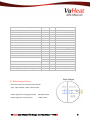
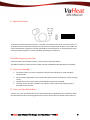
User Manual for VHS Single-Jet Heat Meter VHS20 Contents 1. General Description .......................................................................................................................... 3 2. Energy Calculation ............................................................................................................................ 3 3. Display ............................................................................................................................................... 3 4. Installation ........................................................................................................................................ 5 5. Battery ............................................................................................................................................... 6 6. Interfaces ........................................................................................................................................... 7 7. M-BUS Interface ................................................................................................................................ 7 8. Pulse Output Device ......................................................................................................................... 8 9. Optical Interfaces .............................................................................................................................. 9 10. Radio Frequency Interface: ............................................................................................................... 9 11. Notes On Assembly: .......................................................................................................................... 9 12. Notes On Glycol & Inhibitor.............................................................................................................. 9 13. Warranty .......................................................................................................................................... 10 14. Contact ............................................................................................................................................ 10 VuHeat User Manual for Single-Jet Heat Meter ~ VHS20 2 1. General Description This manual has been written to inform end users and installers of the properties, parameters, operation and installation of VuHeat single‐jet heat meters (VHS20). Heat meters are designed to meet the needs of measurement in heating, hot water and chilled water applications. (Hybrid / change‐over versions available for cooling & heating measurement) Complete heat meter is made up of: Single‐Jet flow meter A pair of PT1000 sensors Heat calculator unit (Integrator) 2. Energy Calculation Q = mc Δt Heat energy is calculated using the formula above. Q = calculated energy m = amount of water passing through the meter Δt = Supply and return water temperature difference C = fixed 3. Display The Integrator unit features a liquid crystal display (LCD) with digits and special characters. There are three display menu’s. Main Statistics Technical All recorded data can be recalled via the button on the top of the device. A short press of this button recalls the data for the chosen menu display. In order to change the menu, keep the button pressed for more than 3 seconds. After 3 minutes the device automatically returns to the main cycle. Main Menu The main menu initially displays the values for the current date and by keeping the button pressed for 3 second the values for the last 12 months can be displayed one by one. VuHeat User Manual for Single-Jet Heat Meter ~ VHS20 3 Display items: 1. 2. 3. 4. 5. 6. 7. 8. 9. 10. Accumulated energy in k/MWh Display segment test Accumulated quantity of water in m3 Actual flow rate in m3/h Return temperature Supply temperature Temperature difference Serial Number Software Version Hours of operation Change display item by depressing the button once. VuHeat User Manual for Single-Jet Heat Meter ~ VHS20 4 4. Installation The flow direction is marked on the heat meter by an arrow. Both the heat meter and temperature sensors are to be installed in the same circuit of the heating plant, for correct operation. VHS heat meters can be installed horizontally or vertically (inclined max. 90°). It is recommended that you install a dirt filter before the heat meter and a stop cock before and after the meter so that it can be removed if required without the need to drain down the system. If installed vertically, the heat meter can be rotated around the vertical axis. The Integrator can be rotated in steps up to 270° for easier viewing. In general, proper operation requires the meter to be full of water with a stable flow. Carefully consider the installation location and other requirements before installing such as; system design, future installations, usage and maintenance. The installation location must avoid direct exposure to sunlight, flooding, freezing temperatures and contamination. Before installing the heat meter make sure that all welding debris, metal burrs and sealing material have been cleaned out of the pipe. Ensure that the arrow direction on the meter is in accordance with the water flow direction. The heat meter must be installed as far away as possible from flow disturbances such as valves, three‐way tubes, elbows, water pumps and filters. The heat meter cannot be installed at the suction side of the pump. Install the temperature sensors as per the stickers. Don't split or mix the paired temperatures sensors nor shorten or lengthen cables. Avoid installing the heat meter on horizontal pipes with downward water flow and do not install at the free outlet of vertical pipes. Heat meters must not be installed at the top of the system where air bubbles can collect. VuHeat User Manual for Single-Jet Heat Meter ~ VHS20 5 DN 20 3 Normal flow (qp) m /h Body thread Connection thread Height (mm) Length (mm) 2.5 1" 3/4" 80.2 129 5. Battery VHS heat meters are equipped with a lithium battery. This battery must not be opened by force, be short‐circuited or exposed to water or temperatures exceeding 80°C. Empty batteries, electronic instruments or components should be disposed of properly at suitable collection centres or returned to us under our obligations to the WEEE Directive 2002/96/EC. VuHeat User Manual for Single-Jet Heat Meter ~ VHS20 6 6. Interfaces VHS heat meters have M‐Bus, optional wM‐Bus (RF 868) and Pulse Output interfaces. 7. M-BUS Interface M‐bus is an inexpensive and widespread network communication protocol for remote meter reading and data capture. It is suitable for small or large numbers of heat meters and is a serial digital communication interface that allows for very long transmission distances using industry standard cables. VHS heat meters are equipped with M‐bus by default, which is delivered via two‐wire cable, which can be lengthened with suitable cable (2 x 0.75 mm and screened). M‐Bus voltage is 12‐24 V DC or 24‐36 V DC. M‐Bus communication baud rate is 2400 for VHS heat meters. Our heat meters are tested to 0.001 m3 and 0.001 kWh resolution. Parameter Symbol Unit Model ‐ ‐ ‐ ‐ VHS20 Class 2 Qmin °C 5 Qmax °C 90 ΔQmin K 3 ΔQmax K 85 DN ‐ ‐ L H mm ‐ ‐ mm mm 20 1” ¾” 130 80.2 qp m3/h 2.5 qs 3 m /h 5 Minimum Flow Rate qi 3 m /h 0.05 Upper Limit of Thermal Power Ps kW 500 Type Accuracy class (MID) Limits of Temperature Limits of Temperature Difference Nominal Diameter Body Thread Connection Thread Length Height Permanent Flow Rate Maximum Flow Rate VuHeat User Manual for Single-Jet Heat Meter ~ VHS20 7 Maximum admissible working pressure Maximum Pressure Loss Installation Position Installation Place Protection Degree Climatic Class Environmental Class Mechanical Class Electromagnetic Class Indicating device Units Displayed Interfaces Software Version / Check Sum Heat medium / Carrier Resolution of LCD Battery Battery Life Output Signal (Pulse) for Rate Output Signal (Pulse) for Testing PS Pl ‐ ‐ ‐ ‐ ‐ ‐ ‐ ‐ ‐ ‐ ‐ ‐ ‐ ‐ ‐ ‐ ‐ ‐ Bar Bar ‐ ‐ ‐ °C ‐ ‐ ‐ ‐ ‐ ‐ ‐ ‐ m3 kWh V Years ‐ ‐ 16 0.25 Horizontal / Vertical Flow or Return(default) IP54 +5 to +55 A M1 El LCD 8 digits kWh, MWh, °C, m3/h, m3 M‐BUS, wM‐BUS, PULSE V 1.66 / CRCI6, OXFF Water 999999.99 999999.99 3.6 >5 1 kWh/Pulse 0.05 kWh/Pulse 8. Pulse Output Device VHS heat meters have a pulse output option. Type : Opto‐Coupler 2‐Wire, Max.35V DC, Output signal for testing (type/levels): 0.05 kWH /pulse Output signal for rate operation: 1 kWh / Pulse VuHeat User Manual for Single-Jet Heat Meter ~ VHS20 8 9. Optical Interfaces 2 3 4 5 RXD TXD DTR SG Receive Data Transmit Data Data Terminal Ready Signal Ground An optical, infrared transmitter/receiver is situated in the bottom left corner of the front panel, in accordance with the EN 61107 standard. The data format complies with IEC 870 in start mode and can be subsequently changed to a format specified by the manufacturer. A standard optical head with a permanent magnet is used to read data and configure tariff limits. 10. Radio Frequency Interface: VHS heat meters have a Radio Frequency output option (Wireless M‐Bus). The Radio Frequency communication module operates at 868 MHz wM‐BUS (EN 13757‐4:2005). 11. Notes on Assembly: Install heat meter only after completion of pipework and flushing to avoid damage or contamination Do not install temperature sensors within the thermal sphere of influence of other heating circuits Temperature sensor cables must not be folded, shortened or extended. The Flow sensor must be installed in the supply or return side of the heating circuit as specified at time of order 12. Notes on Glycol & Inhibitor Contact us or your local distributor for our latest information regarding the use of Inhibitor within the RHI schemes and our operating performance with % Glycol inclusion within system make‐up. VuHeat User Manual for Single-Jet Heat Meter ~ VHS20 9 13. Warranty VuHeat warrants the products sold hereunder, properly used and properly installed under normal circumstances and service as described in this user's manual, shall be free from faulty materials or workmanship for 180 days for OEM products, and 365 days for non‐OEM products from the date of shipment. This warranty period is inclusive of any statutory warranty. Any repair or replacement serviced product shall bear the same terms in this warranty. 14. Contact Distributed by: VuHeat User Manual for Single-Jet Heat Meter ~ VHS20 10