1
United States Patent [19]
[11] Patent Number:
Pogue, Jr.
[45]
[54]
RADIO RECEIVER SYSTEM INCLUDING A
CONTROL UNIT AND A REMOTE UNIT
[75] Inventor: Russell W. Pogue, Jr., Kokomo, Ind.
[73] Assignee:
[5 7]
n .
[22]
Filed:
Int Cl 3 _ _
ABSTRACT
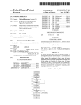
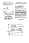
. An automobile radio receiver system includes a control
unit located in the passenger compartment and a remote
[2]] Appl' NO" 175A”
[51]
Mar. 5, 1985
Primary Examiner-Gareth D. Shaw
Assistant Examiner-Daniel K. Dorsey
Attorney’ Agent’ or ?rm-Albert F‘ Duke
General Motors Corporation, Detroit,
Mich.
Date of Patent:
4,503,513
unit, for example, in the trunk compartment of the auto
Aug. 4, 1980
I‘i_
l __
mobile. The control unit includes a master microcom
G06]? 15/16, H04B 1/38
puter which controls a display and responds to key
[52] us‘. Cl. ...'.'.'.'.'.'.'."£11.": ........... .. 364/900' 455/77’455 /1 51'
‘ward inputs- The "mm uni‘ imludes "16 radio "
ceiver which is controlled by a slave microcomputer.
[58]
The master and slave microcomputers are intercon
Field of Search
364/200 MS pus’ 900 MS File;
34o/825_63; 455/77’ 151, 152’ 165
nected by a single wire data bus. Data regarding key
_
[56]
board inputs are transmitted to the slave and data re
References cued
U8. PATENT DOCUMENTS
3 79B 611
3/1974
4,122,304
10/1978
4.3!],986
4,147,984
controlling the timing of data transmission thereby per
mitting a relatively imprecise timing base in the slave.
Gallant et al. .................... .. 364/900
Mallien ........... ..
..
4/l979
l/1982 Yee
Coudel
...............................
et al.
.. IMO/‘825.63
25
2
L_
UNH-
___
l
Z5
10 Claims, 13 Drawing Figures
26%
w
CONTROL
l
garding receiver status is transmitted to the master. The
data is interleaved on a bit by bit basis with master
10
i
POWER
DATA LINE
as
REMOTE
AM/FM
UN|T
(18
ca
D
Z0
Z2
2,’
U.S. Patent Mar. 5, 1985
Z5
7
+
POWER
'
,
/
{a
REMOTE
UN|T
Z5
26
PLAYER
E
.L__
CONTROL
T TAPE
l6
4,503,513
26%?
14
,6
g
Sheet 1 of 8
DATA LINE
AM/FM
UNlT
CB
‘\,0 [18 655%
22
5/91
E5
52
5*“
{)
BASS‘
|"I.r-| ["1
1 CB‘i
{ST
.I l___
[O ' ,l__J.,l_J,
@
x
72559511
76
58\ HRo/Zjw 62/ 7? 6'6‘
WM 63 5%’)
9|
g
‘PM AT)"
‘
‘
RCL
'
’
I
2
‘
3
I0 TREB GI
’
4
I
<;:
SET
BAL
<>|
52
Q FADE
G‘
#8
Ii 5&0
CB W58Q] BN/OFF]
#0,} [AM-FMJ
42) ISCANI \ SEEK | [L/DI [RAD cs]
699.2
US. Patent Mar. 5, 1985
Sheet4of8
4,503,513
"- 3/8M SEC_->1-—-5/gM SEC ___t
I T MT
M M
DATA
BIT TRANSMITTED
BY
MASTER
\\O//
TU
M M M
M
.
T
M
M
E E
E
E E E
E
E
E
O I
2
3 4 5
6
7
O
O
O
BY
SLAVE__
\\O//
L.
“01/
AV,
0
I
\\ 1/
004/
\\‘I/
\\ ll
l
O
_
l
SLAVE DATA STROBE
A
L
MASTER DATA STROBE
5
SAvE MACHINE
CONTEXT
HICH
“ME?
TIME 5
TIME 0
SET UP FOR
T'ME 5
INTERRUPT
DRIVE
I
NEXT 1D|G|T
DEEREMENT
SOFJIIX’ERRE
1
URDATE
HALF SECOND
“ME?
RELEASE
OUTPUT SERIAL
DATA B‘T
BUS
LOW
5
TIME 2 |
4
T
RESTORE
“ASTRA-T
DATA BUS
+
SET UP FOR
TIME 0
INTERRURT
511;“
DATA BIT FROM
REMCiTE UNIT
SET up DATA
TO BE OUTPUT
AT TIME 2
SEE Fl(i3.6a
READ AND STORE
KEYBOARD INFO
U.S. Patent Mar. 5,1985
Sheet50f8
NOT
READY
"
SAVE MACHINE
CONTEXT
WHICH
TIME
TIME I
—_'—1
sET UP FOR
TIME 7
INTERRUPT
?
TIME 7
ENggEFgIIIL
i
sET up FOR
TIME I
INTERRURT
DECREMENT
SOFTWARE
TIMERS
TIME aI
DO SERIAL
1/0 SEE Fl (3 7a
1
RESTORE MACHINE
CONTEXT
4,503,513
US. Patent
Mar. 5, 1985
Sheet 7 of 8
SET DISPLAY
TIMER FOR 5
SECONDS
CONVERT DATA
TO 7 SEGMENT
CODE AND LOAD
OUTPUT BUFFER
FORMAT DATA TO
DISPLAY APPRO
PRIATE INDICATOR
YES
4,503,513
LOAD RESULT
I N OUTPUT
BUFFER
IS
DATA >
PREDETERMINED
MAXI MUM
TDD.
DISPLAY
YES
STORE PREDETERMINED
MAXIMUM LEVEL AT
VOLUME LEVEL
ADDRESS
NO
?
DO TI ME SET
FUNCTION
LOAD OUTPUT
BUFFER WITH
T.O.D. SEGMENT
DATA
INCREMENT
‘
TDD.
/2 SECONDS
I
3/910
DISCREMENT
DISPLAY TIMER
US. Patent Mar. 5, 1985
INITIALIZE PORTS
RAM AND TWIER
Sheet8of8
4,503,513
TYPE
OF OUTPUT
COMMAND
ADDRESS
SERIAL
I/O READY
?
SERIAL
NO
I/O READY
OUTPUT DUMP
COMMAND
OUTRUT DATA
AT ADDRESS
SERIAL
NO
T
1/0 READY
7
SERIAL
'
I/o READY
YES
EXCHANGE I/O
P
YES
vvORD AND STORE
IN NEXT MEMORY
OUTPUT ADDRESS
LOCATION
'
OR
COMMAND
AND SAvE INPUT
LAST
NO
LOCATION
?
INITIALIzE D/A
CONVERTER AM FMéLCB
SYNTHESIZERS
INTERRRET INRUT CODE
EXTERNAL INPUTS (STOR
TARE,STEREO
CONTROL
SOFTWARE RECEIvER.
TIMERS
ECT.) AND
TO
OUTPUT A CODE lNDlCATINC
ACTTON TO BE TAKEN BY
CONTROL UN 1 T
|_
..____
NO
1
4,503,513
RADIO RECEIVER SYSTEM INCLUDING A
CONTROL UNIT AND A REMOTE UNIT
FIELD OF THE INVENTION
This invention relates to radio receiver systems and,
more particularly, to an automobile radio receiver sys
tem comprising a control unit and a remote unit both of
which are under the control of respective microcom
puters which communicate one with the other over a
single wire bi-directional serial data bus.
BACKGROUND OF THE INVENTION
For a number of years various proposals have been
put forth to relocate the radio receiver from its present
position in the instrument panel to a remote location
such as the trunk area of the automobile. More recently,
a proliferation of display functions in the automobile
and a concurrent decrease in the available space in the
instrument panel area has caused increased interest in
such proposals. There are a number of advantages asso
2
crocomputer to tune the receiver to a new station or
adjust the audio control settings. When the control unit
commands are carried out, the new status of the re
ceiver is transmitted from the remote unit microcom
puter to the control unit microcomputer for display and
storage. The control unit microcomputer is continu
ously energized from the vehicle battery whereas the
remote unit microcomputer is energized through an
ON/OFF switch by the operator. Thus when the re
mote unit is powered down, the receiver status informa
tion is retained by the control unit. When the remote
unit is powered up, the status information stored in the
control unit microcomputer is dumped to the remote
unit microcomputer to establish the previous status of
the receiver.
The two microcomputers operate under a master
slave relationship. The control unit microcomputer is
the master and is provided with a precise time base in
order to provide an accurate time of day display. The
control unit microcomputer therefore controls the start
of each data bit transfer and a bit of data is transferred
between the master and slave each bit transfer period.
In other words the data bits are interleaved.
ciated with removing the receiver from the instrument
panel area. For example, relocation permits size and
shape considerations to be made without reference to
instrument panel design. Also, certain advantages asso 25 A more complete understanding of the present inven
tion may be had from the following detailed description
ciated with service and maintenance of the receiver
which should be read in conjunction with the drawings,
may occur. One of the major drawbacks associated with
in which:
prior proposals is the increased cost associated with the
additional wiring and connectors required between the
BRIEF DESCRIPTION OF THE DRAWINGS
remote receiver unit and the control unit.
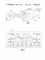
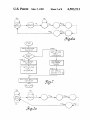
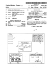
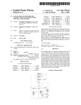
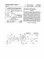
FIG. 1 is a block diagram of the receiver system;
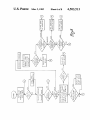
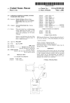
FIG. 2 is a front view of the panel of the control unit;
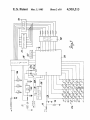
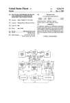
FIG. 3 is a block diagram of the control unit;
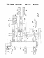
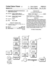
FIG. 4 is a block diagram of the remote unit;
ent invention to provide a communication system in
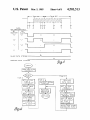
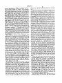
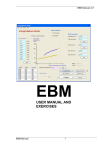
FIG. 5 is a timing diagram of a bit transfer period;
cluding a microcomputer based control unit and a mi 35
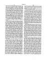
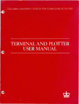
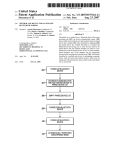
FIGS. 6 and 7 are flow charts of the timer interrupt
crocomputer based remote unit interconnected by a
subroutines in the master and slave microcomputers,
single wire bidirectional data bus and wherein the mi
respectively;
crocomputer in the control unit controls the timing of
FIGS. 60 and 7a are state diagrams depicting the
the communication of data between the two units.
It is another object of the present invention to pro 40 serial I/O status of the master and slave microcomput
ers when the timer interrupt subroutines of FIGS. 6 and
vide a radio receiver system wherein a master mi
7 respectively are entered;
crocomputer monitors operator actuable switch inputs
FIGS. 8 and 9 are flow charts depicting the main
and transmits commands to a slave microcomputer
program of the master microcomputer;
which controls the receiver in accordance with the
commands and transmits receiver status information to 45
FIG. 10 is a flow chart of the Time-of-Day subrou
tine in the master microcomputer; and
the master microcomputer which utilizes the status
SUMMARY OF THE INVENTION
With the foregoing in mind it is an object of the pres
information to control a display.
It is another object of the present invention to pro
vide a radio receiver system including a remote receiver
unit and a control unit each comprising a microcom 50
puter interconnected by a single wire bidirectional data
bus and wherein a bit of data is transferred in both
directions during a bit transfer period.
In accordance with the present invention an automo
FIG. 11 is a flow chart of the main program of the
slave microcomputer.
DESCRIPTION OF THE PREFERRED
EMBODIMENT
Referring now to the drawings and initially to FIG. 1,
the receiver system of the present invention comprises a
control unit generally designated 10 and a remote unit
bile radio receiver system is provided which includes a 55 generally designated 12. The control unit 10 is powered
control unit mounted within ready access to the opera
from the vehicle battery 13. Power is supplied to the
tor of the vehicle. A remote unit is interconnected with
remote unit 12 and a tape player 14 from the ignition
the control unit by a power supply line and a single wire
switch 15 through a manually actuable ON/OFF
bidirectional data bus. The data bus interconnects two
switch 16. The control unit 10 and remote unit 12 each
microcomputers, one of which is located in the control 60 include single chip microcomputers which communi
unit and the other of which is located in the remote unit.
cate one with the other, over a serial bidirectional data
The control unit includes an input keyboard and an
bus line 18. A suitable microcomputer is the 8048,
output display. The control unit microcomputer re
which includes an 8-bit event counter/timer controlla
sponds to keyboard inputs by the operator and transfers
ble by program instructions to perform such functions
coded data corresponding to the keyboard status to the 65 as counting external events and generating accurate
remote unit microcomputer which decodes the data and
time delays. The 8048 is described in the User’s Manual
controls the receiver in accordance therewith. For ex
which is incorporated herein and is available from
ample, the data may command the remote unit mi
INTEL Corporation, Santa Clara, California. The re
3
4,503,513
mote unit 12 receives inputs from a CB microphone 20,
a CB antenna 22, an AM/FM antenna 24, and provides
output signals to a plurality of speakers, two of which
are shown and designated 26 and 28.
The control unit 10 is located within ready access to
the vehicle driver, for example, in the instrument panel
of the vehicle and may include a front panel 30 such as
shown in FIG. 2. Protruding through the panel are a
plurality of operator actuable keys 32-68 for controlling
the remote unit 12. A digital display is viewable through
the panel for displaying time-of-day, AM/FM fre
quency, or CB channel information. Enunciators 72 are
provided to indicate the status of the receiver. A plural
ity of momentary contact switches (FIG. 3) are actuat
able by the keys for selecting a plurality of radio operat
ing conditions, such as AM/FM, SCAN, SEEK and
LOCAL/DISTANT. The ON/OFF power switch 16
actuable from the key 40 is preferably a push-push type
switch which mechanically latches in either the ON or
4
receives a ?ltered input from the vehicle headlamps
dimmer potentiometer (not shown) which controls the
brightness of the display. Panel lights 146 illuminate the
legends on the keys.
Data is received from the remote unit 12 over the
data bus 18 connected to a data input pin of the mi
crocomputer 100. A protection network generally des
ignated 168 protects the microcomputer 100 from tran
sients on the data bus. The data bus 18 is connected to
the collector of a drive transistor 172 which has its
emitter grounded and its base connected to the data
output pin of microcomputer 100.
Referring now to FIG. 4, the remote unit 12 includes
a microcomputer 200 which controls an AM/FM re
ceiver 204 and a CB transceiver 206. The microcom
puter 200 controls the tuning of the receiver 204 by
providing a tuning code number to a frequency synthe
sizer 202, which in turn provides a tuning voltage to the
receiver. The microcomputer 200 also provides an
AM/FM
input to the receiver 204 to select the proper
20
OFF positions.
band and an L/D input to set the threshold level at
The TUNE, VOLUME, BASS, TREBLE, BAL
which the STOP signal will be generated during a
ANCE, FADE and CB SQUELCH keys, respectively,
SEEK operation. The microcomputer 200 provides a
each selectively actuate two momentary contact
code number to the CB transceiver 206 which includes
switches. The switches control the designated functions
a frequency synthesizer for tuning the transceiver in
25
in two directions by pressing in the locations of the
accordance with the code. The microcomputer 200
arrows shown. By pressing in the middle of the BASS,
provides a code to an audio switch 210 which routes the
TREBLE, BALANCE or FADE key, both switches
audio from the receiver 204, tape player 14, or CE trans
may be closed simultaneously and be interpreted as a
ceiver 206, to an audio processor circuit 208. The fourth
mid-position command. The TUNE key 56 may be
actuated to selectively increment or decrement the 30 code to the switch 210 mutes the audio. The BASS,
TREBLE, BALANCE and VOLUME settings are
entertainment or CB receiver by one station or channel
determined by dc control voltages applied to the circuit
per actuation. By concurrently actuating the increment
208. The dc control voltages correspond to digital data
and decrement switches of the TUNE key 56, the tun
provided by the computer 200, which is converted to
ing rate may be increased with the direction dependent
on the sequence of actuation. Four AM, FM and CB 35 analog signals by a D/A converter 212. The output of
the audio processor circuit 208 and the FADE control
stations may be preset for push-button recall by tuning
voltage is fed to ampli?ers 222 and 224, which drive the
the receiver using the TUNE or SEEK keys 56 or 46
speakers 26 and 28. The microcomputer 200 receives
until a desired station is displayed and thereafter sequen
status inputs such as a STEREO and STOP inputs from
tially actuating the SET key 70 and one of the four
numbered keys 62-68. Time of day is normally dis 40 the receiver 204 and two inputs from the CB transceiver
206 indicating when the CE is in the transmit mode and
played but the station to which the receivers are tuned
may be recalled by actuating the RCL key 60. Switch
actuators 74 and 76 labeled HR and MIN are provided
for time setting purposes.
Referring now to FIG. 3, the control unit microcom 45
puter is generally designated 100. A voltage regulator
102 provides a 5-volt input to the microcomputer 100
from the vehicle battery 13. Capacitors ?lter the input
and output of the regulator 102. The microcomputer
when the received signal strength is above the
SQUELCH level. The microcomputer 200 also re
ceives a status input from the tape player 14 indicating
whether a tape is inserted. A voltage regulator 216
provides 5 to 8 volt regulated outputs as necessary to
the various components when power is supplied from
the switch 16 to the remote unit.
The data bus 18 is connected to a data input pin
100 monitors the status of the ignition switch which is 50 through a protection network generally designated 226
that is driven from the data output pin through a buffer
transistor 228. The bus 18 is connected to the regulated
114 and 116 and ?lter capacitor 118. Timing input to the
5-volt line through a pull-up resistor 230. Thus, the bus
microcomputer 100 is provided by a quartz crystal 120.
is normally high in its inactive state unless pulled down
The microcomputer 100 receives a power-up reset input
to its active state by the microcomputer 100 or the
from an initialization circuit 128 when the battery 13 is
microcomputer 200. By locating the resistor 230 at the
connected to the circuitry. The key actuated switches
remote unit 12, the data bus 18 will go low when power
of the control unit 10 are arranged in a matrix con?gu
is removed from the unit 12. This permits the state of
ration generally designated 134. The microcomputer
the data bus to provide an indication of whether the unit
100 is programmed to scan and encode the status of the
12 is powered up making it unnecessary to monitor the
switch matrix in a conventional manner.
ON/ OFF switch 16.
The microcomputer 100 controls a 5-digit, 7-segment
An R-C network 232 provides a time base for the
display through a digit driver 138 and a segment driver
microcomputer 200. Since the microcomputer 200 acts
140 in a conventional manner. The display includes a 3%
as a slave when communicating with the microcom
digit display 136 and an enunciator 137. The enunciator
137 includes six LED’s which are energized to respec 65 puter 100, precise timing can be achieved in the slave
microcomputer 200 with a relatively unprecise and
tively illuminate the designated legends depending on
inexpensive time base. This results from the fact that the
the status of the receiver. In addition, to the three select
data bit rate set by the microcomputer 100 is precise and
inputs from the microcomputer, the digit driver 138
connected thereto through voltage dividing resistors
5
4,503,513
because each bit is synchronized as explained hereinaf
ter. An initialization circuit 234 provides a power-up
reset to the microcomputer 200.
6
TIME 6 the microcomputer 100 inputs the data bit
transmitted by the microcomputer 200. The microcom
puter 200 allows the bus to return high at TIME 7 to
As previously indicated, the function of the master
ensure that the bus is high at the start of the next bit
microcomputer 100 is to read the status of the switch 5 transfer period. It will be apparent that while the afore
matrix, control the display and control the timing of
mentioned activity at TIME 4 is shown to occur before
data communication with the slave microcomputer 200.
TIME 5, the only requirement for accurate communica
The microcomputer 100 outputs a speci?c code for
tion of the data bit from the microcomputer 200 to the
each of the individual keys when it is pressed. If no key
microcomputer 100 is that this activity occurs after
is being pressed, a NULL code is output. The various t. . 0 TIME 3 and before TIME 6.
codes may be stored in a look-up table in the on-chip
The transfer of data between the two microcomput
ROM of microcomputer 100. All data transfers between
ers is under the control of the timer in the master mi
the microcomputers 100 and 200 are initiated by the
crocomputer 100. During the power-up initialization
master microcomputer 100 and it sets the pace. For
routine of the master microcomputer 100, the timer is
synchronization purposes, each group of eight bits is 5 present to generate an interrupt after the initialization
preceeded by a start bit. The response to the start bit is
subroutine is completed. The ?owchart in FIG. 6 de
an acknowledge bit from the slave microcomputer 200
picts the timer interrupt service subroutine for the mas
indicating whether or not it is ready for a transfer to
ter microcomputer 100. In response to the interrupt the
take place. If the slave microcomputer 200 is not ready,
machine context is saved and a determination is made as
then the master microcomputer reinitiates a start bit and
this continues until the slave microcomputer 200 is
ready. Then the eight bits of a data word follow without
interruption. When the slave microcomputer 200 re
to whether the interrupt occurred at TIME 0 or TIME
5 of the bit transfer period. This may be done by testing
a flag. If this interrupt occurred at TIME 0, the timer is
preset to enerate another interrupt in i millisecond.
ceives a message it checks a look-up table to determine
After the timer is preset, the data bus is pulled low to
the function to perform. If, for example, the TUNE key 25 initiate the bit transfer period. Since the timer interrupt
was pushed, the slave microcomputer 200 either incre
subroutine is entered each millisecond, certain time
ments or decrements the present station, outputs the
related functions are performed during the interrupt
new station number to the frequency synthesizer 202
subroutine. For example, one digit of the display is
and outputs the new station code to the master mi
crocomputer 100 for display. If the SEEK switch is
activated, the microcomputer 200 initiates a search
through the appropriate AM, FM or CB band until a
signal strength of a predetermined level is received.
This is accomplished by incrementing the frequency
code number supplied by the microcomputer 200 to the
appropriate frequency synthesizer and monitoring the
refreshed each time this subroutine is entered. Also a
half second timer is updated for use in incrementing
Time-of-Day. At TIME 2, the data bus is released to
output a “0” bit to the remote unit microcomputer or is
held low to output a “1” bit. A return from the subrou
tine is executed after the machine context is restored.
The TIME 5 interrupt in the microcomputer 100
occurs 5‘ milliseconds after the TIME 0 interrupt. At
this time the microcomputer 100 releases control of the
STOP output of the receiver 204 or signal strength
output of the transceiver 206. The implementation of
data bus and the microcomputer 200 may assume con
the SCAN function is similar to the SEEK function.
trol by pulling the data has low to transmit a "l". Oth
When SCAN is commanded, the microcomputer 200 40 erwise a “O” is transmitted. After the microcomputer
enters the SEEK mode and when a listenable station is
acquired remains on the station for a predetermined
time interval. If while on station the SCAN switch is
activated, the receiver will remain on station, otherwise
the SEEK mode will be reentered.
45
The transfer of data between the two microcomput
ers 100 and 200 will be described with reference to the
100 releases control of the bus it sets its timer to gener
ate the next interrupt in 5 milliseconds. Thereafter, the
data bits placed on the line by the microcomputer 200 is
stored in the microcomputer 100 and the next data bit is
set up for output (during TIME 2) to the microcom
puter 200. Thereafter, the keyboard is read, the machine
context is restored and control is returned to the main
timing diagram shown in FIG. 5. A data bit is trans
program. As shown by the state diagram in FIG. 6a, the
ferred between the two microcomputers 100 and 200
master microcomputer 100 outputs a “0” whenever it is
each bit transfer period which is shown as consisting of 50 NOT READY to transmit. When the master mi
a l millisecond time interval. The microcomputer 100
crocomputer 100 is READY to transmit, it outputs a
causes the data bus to transcend from a high to a low
level to initiate a bit transfer period at TIME 0. The
“l” and goes to a state where it waits until a “l” is
received from the slave microcomputer 200. When the
microcomputer 100 causes the data bus to go high at
master microcomputer 100 inputs a "1” from the slave
TIME 2 if a “0” data bit is to be transmitted and main 55 microcomputer 200, it outputs the ?rst data bit C1.
tains the line low if a “1” data bit is to be transmitted. At
Thereafter it progresses through each state until the last
TIME 3 the microcomputer 200 inputs the data bit
bit of the word R8 is received from the slave microcom
transmitted by the microcomputer 100. At TIME 5
puter 200 at which state the master microcomputer 200
microcomputer 100 releases the data bus so that it may
outputs a “0” indicating the NOT READY state.
return to a high state. Transmission of a data bit from 60
Whenever the remote unit is energized from the
the microcomputer 200 to the microcomputer 100 is
ON/OFF switch 16, the slave microcomputer 200 en
accomplished by the microcomputer 200 controlling
the state of the bus after TIME 3. If a “0” data bit is to
be transmitted, the microcomputer 200 allows the bus to
return to a high level at TIME 5 or to remain at the high
level established at TIME 2 for the remainder of the bit
transfer period. To transmit a “1” data bit, the mi
crocomputer 200 pulls the line low at TIME 4. At
ters an initialization routine which sets its event counter
to generate an interrupt in response to a high to low
transition on the data bus. As previously indicated, this
transition occurs when the microcomputer 100 initiates
the bit transfer period at TIME 0. The ?owchart in
FIG. 7 depicts the timer interrupt subroutine for the
slave microcomputer 200. After the machine context is
7
4,503,513
saved, a determination is made as to whether the inter
rupt occurred at TIME 1 or TIME 7. If the interrupt
occurred at TIME 1, the event counter is used as a timer
and is present to generate an interrupt, in for example i
millisecond (TIME 7), after the microcomputer 200 has
read (TIME 6) the data bit placed on the line by the
microcomputer 100. During TIME 1, the microcom
puter 200 decrements various software timers used in
controlling the receiver. Beginning at TIME 3 the slave
microcomputer 200 does the serial input and output of
data and thereafter restores the machine context and
returns control to the main program. As shown in the
state diagram of FIG. 7a, the bit output by the slave
microcomputer 200 depends on its state during the
TIME 1 interrupt. The slave microcomputer 200 out
puts a “0” if it is NOT READY to transmit data. When
the slave microcomputer 200 is READY to transmit, it
8
100 receives a DUMP command, the dump is reinitial
ized.
In the RUN mode, the keyboard is encoded and the
encoded word is loaded in a register for output to the
remote unit and the complete word just received from
the remote unit is operated upon. The microcomputer
200 transmits data words and/or control words. A con
trol word may be either an address for the data word or
a command. If the word received from the microcom
puter 200 is data, it is saved and the program exits to
LOOP A. When an address word is received, the data
word previously transmitted and saved is stored at the
address speci?ed. This updates the RAM in the mi
crocomputer 100 with the status of the receiver so that
the receiver may be initialized in the event of a DUMP
command. A data word is transmitted prior to its associ
ated address word to insure that only valid data will be
loaded into the address in the event of a power-down
assumes a READY state and waits in this state until it
before both address and data words are received. As
receives a “1" from the master microcomputer 100
whereupon it outputs a “l”. Thereafter each bit C1-C8 20 shown in FIG. 9, the type of data is determined from
the associated address. If the address is allocated to an
of the word transmitted by the master microcomputer
AM, PM or CB frequency, the new frequency data
100 is input and each bit R1-R8 of the word to be sent
word is converted to the appropriate 7-segment code
to the master microcomputer 100 is output. Returning
and loaded in the output buffer and a display timer is set
to FIG. 7, if the interrupt occurred at TIME 7, the serial
output is terminated by releasing control of the data bus 25 for a 5 second display of the frequency. If the address
corresponds to one of the status indicators, the data
18, and the event counter is preset to generate an inter
word is converted to an appropriate format for display
rupt at TIME 1.
and stored in the output buffer. If the address corre
Referring now to FIGS. 8 and 9, the ?owchart of the
sponds to the VOLUME level, the data is compared
major loop of the master microcomputer 100 is shown.
with a predetermined maximum initial turn-on volume.
When power is ?rst applied to the microcomputer 100
If greater than the predetermined maximum for initial
from the vehicle battery, an initialization routine is
turn-on, the data at the volume level address is replaced
entered which initializes the I/O ports, RAM and timer
with the predetermined level. This insures that the ini
with the desired startup data. Thus, initial preset AM,
tial turn-on volume is at a reasonable level, such as
FM and CB channels and audio setting are established,
mid-range. Returning to FIG. 8, if the control word is a
the timer is preset to generate an interrupt and initial
command, the type of command is determined from a
flag conditions are established. After initialization, the
look-up table. Typical commands are DISPLAY TIME
timer is started and the major loop is entered. The pro
of DAY which is appropriate when a tape is inserted in
gram of the microcomputer 100 executes LOOP A until
the tape player and DUMP MEMORY which is appro
a complete byte of data has been received from the
microcomputer 200 and a new byte of data is ready for 40 priate when the microcomputer 200 is powered-up.
As shown in FIG. 10, when the TOD subroutine is
transfer to the microcomputer 200. During LOOP A, a
called, the Time-of-Day counters are incremented. lf
Time-of-Day (TOD) subroutine is called each half
Time-of-Day is being displayed, the operator may acti
second, during which the Time-of-Day counters are
vate the minutes or hours switches to set the display to
incremented and the Time-of-Day counters may be set
the correct time. During the TOD subroutine, the dis
by the operator to re?ect the correct time. The flow
play timer is decremented and when the 5 second period
chart for the Time-of-Day subroutine is shown in FIG.
for display of frequency has timed out, the output buffer
10. Also, during LOOP A the microcomputer 100 is
is loaded with 7-segment data for display of Time-of
placed in the display or standby mode depending on the
Day.
state of the ignition switch and the RECALL switch.
A ?owchart of the major loop for the slave unit mi
The standby mode is a low power condition where the 50
crocomputer 200 is shown in FIG. 11. As previously
display is turned off whenever the ignition switch is
indicated, when power is applied to the remote unit
turned off. During this standby mode, the RECALL
from the ON/OFF switch 16, the program enters an
switch may be actuated to set up conditions for energiz
initialization subroutine which initializes the ports,
ing the display for 5 seconds.
clears the RAM locations and places the timer in its
If a new data word is ready for transfer to the mi
event counter mode. When the master microcomputer
crocomputer 200, the program of the microcomputer
100 indicates it is READY to receiver data, the slave
100 does a test to determine whether it should operate in
microcomputer 200 transfers a DUMP MEMORY
the DUMP or RUN mode. The DUMP mode is com
command to the microcomputer 100. In response to this
manded by the microcomputer 200 each time it is pow
command, the microcomputer 100 transfers the data
ered-up from the ON/OFF switch 16 in order to rees
corresponding to the conditions existing when the re
tablish the conditions existing at power-down. During
mote unit 12 was powered-down as well as the
the DUMP mode, the data in the RAM of the mi
AM/FM/CB presets for the keys 1-4. After the RAM
crocomputer 100 needed to reestablish the operating
of the microcomputer 200 is loaded with this data, the
conditions prior to power-down is transferred to the
RAM of microcomputer 200. Once the last location has 65 D/A converter 212 and the AM/FM synthesizer 202
and CB transceiver 206 are initialized.
been dumped to the remote unit, a flag is set so that the
Once the microcomputer 200 is operating under the
next time through the loop, the RUN mode will be
conditions existing at power-down, the microcomputer
entered. If during the DUMP mode the microcomputer
4,503,513
100 transmits keyboard status information which is de
coded by the microcomputer 200 to determine what
action should be taken. For example, if the decoded
information corresponds to one of the audio settings,
such as VOLUME, then the information will be in the 5
form of a step change either up or down in the level of
the audio setting. Control is accomplished by formating
and serially feeding the new data to the D/A converter
212 which produces the new analog output voltage.
The microcomputer 200 also responds to the various
external inputs such as STOP and to various software
timers such as a SCAN timer and MUTE timers, to
control the operation of the receiver. When the mi
crocomputer 100 is READY to receive information the
microcomputer 200 outputs either a command or data
followed by an address indicating what action should be
taken by the microcomputer 100, for example, display
the new station or update the status information.
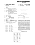
The embodiments of the invention in which an exclu
sive property or privilege is claimed are de?ned as
10
timing of the transfer of said data by periodically initiat
ing a bit transfer period during which a bit of data is
transmitted from the master computer to the slave com
puter and a bit of data is transmitted from the slave
computer to the master computer.
3. The system de?ned in claim 2 wherein said remote
unit includes means for normally placing said data bus
to return in an inactive state when power is applied to
said remote unit, said master computer placing said data
bus in an active state to initiate said bit transfer period
and permitting said data bus to return to said inactive
state after a relatively short or relatively long time inter
val depending on the binary coded bit to be output to
said slave computer, said slave computer reading the
state of said data bus after expiration of said short time
interval and prior to expiration of said long time inter
val and thereafter assuming control of the data bus by
placing said data bus to said active state to output one
binary coded bit or permitting said data bus to return to
said inactive state to output the other binary coded bit,
said
slave computer releasing control of said data bus a
1. A communication system comprising a control unit
predetermined time interval after initiation of said bit
including a master computer and a remote unit includ
transfer period, said master computer reading the state
ing a slave computer, a single wire bidirectional data
bus interconnecting said master and slave computers, 25 of said data bus while said slave computer has control of
said data bus.
output means coupled to said slave computer, input
4. The system de?ned in claim 2 wherein said master
means coupled to said master computer for selecting
computer includes presettable timer means for generat
operating functions of said output means, said master
follows:
ing ?rst and second recurring interrupts, said master
computer communicating information to said slave
computer regarding the status of said input means and 30 computer responsive to said ?rst interrupt for initiating
said bit transfer period and for outputing a data bit to
receiving information from said slave computer regard
said slave computer, said slave computer including
ing the status of said output means, said master com
means for generating a third interrupt in response to
puter controlling the timing of the transfer of said infor
initiation of said bit transfer period and a fourth inter
mation by periodically initiating a bit transfer period
and assuming control of the data bus during a ?rst por 35 rupt a predetermined time interval thereafter, said slave
computer responding to said third interrupt by reading
tion of said period and relinquishing control of the data
the data bit output by said master computer and output
bus during the remaining portion of said period, said
ing a data bit to said master computer, said master com
slave computer responsive to the initiation of said bit
puter responding to said second interrupt by terminat
transfer period for reading the data bus during said ?rst
portion and thereafter assuming control of the data bus, 40 ing the output of said data bit to said slave computer and
for reading the data bit output by said slave computer,
said master computer reading the data bus during said
said slave computer responding to said fourth interrupt
remaining portion, said slave computer relinquishing
by terminating the output of a data bit to said master
control of the data bus prior to initiation of a succeeding
computer.
bit transfer period, whereby a bit is transmitted from the
master to the slave computer and a bit is transmitted 45
from the slave to the master computer during each bit
transfer period.
5. A radio receiver system comprising a control unit
including a master computer and a remote unit includ
ing a slave computer, a single wire bidirectional data
bus interconnecting said master and slave computers,
radio receiver means coupled to said slave computer
ing a slave computer, a single wire bidirectional data 50 and controlled thereby, input switch means coupled to
bus interconnecting said master and slave computers,
said master computer for selecting operating functions
2. A radio receiver system comprising a control unit
including a master computer and a remote unit includ
radio receiver means coupled to said slave computer
of said radio receiver means, said master computer in
and controlled thereby, input switch means coupled to
said master computer for selecting operating functions
cluding memory means for storing data regarding the
status of said radio receiver, display means controlled
of said radio receiver means, said master computer in 55 by said master computer for indicating the status of said
cluding memory means for storing data regarding the
radio receiver in accordance with the data in said mem
status of said radio receiver, display means controlled
ory, means normally applying power to said master
by said master computer for indicating the status of said
computer means for continuously energizing said mem
ory means, means for selectively applying power to said
radio receiver means in accordance with the data in said
memory means, means normally applying power to said
master computer means for continuously energizing
said memory means, for selectively applying power to
said slave computer, said master computer communicat
slave computer, said master computer communicating
data to said slave computer regarding the status of said
input switch means and receiving data from said slave
computer regarding the status of said radio receiver
means for updating said memory means and said display
ing data to said slave computer regarding the status of
said input switch means and receiving data from said 65 means, each data word transferred between said master
slave computer regarding the status of said radio re
computer and said slave computer containing a plural
ceiver means for updating said memory means and said
ity of bits, the bits of the words transferred from the
display means, said master computer controlling the
master computer to the slave computer being inter
11
4,503,513
12
said volume level data exceeds said predetermined max
imum volume level to thereby limit the initialized vol
ume of said receiver means to said predetermined maxi
leaved with the bits transferred from the slave computer
to the master computer.
6. The system de?ned in claim 5 wherein said slave
computer transmits either a control word or a data
mum level.
10. A radio receiver system comprising a control unit
word to said master computer, said control word being
including a master computer and a remote unit includ
either a command to said master computer or an address
where a previously transmitted data word is to be
stored in said memory of said master computer.
7. The system de?ned in claim 6 wherein said slave
ing a slave computer, a single wire bidirectional data
bus interconnecting said master and slave computers,
radio receiver means coupled to said slave computer
computer is responsive to application of power thereto - 0 and controlled thereby, input switch means coupled to
to output an initialization command to said master com
said master computer for selecting operating functions
puter, said master computer responsive to said initializa
of said radio receiver means, said master computer in
tion command for transferring data regarding the status
cluding memory means for storing data regarding the
of said receiver means at power-down to initialize said
status of said radio receiver, display means controlled
receiver means to the status existing prior to power
by said master computer for indicating the status of said
down.
8. The system de?ned in claim 5 wherein said master
radio receiver in accordance with the data in said mem
ory means, means normally applying power to said
computer is provided with a relatively precise time base
master computer means for continuously energizing
and said slave computer is provided with a relatively
imprecise time base, said master computer normally 20 said memory means, power switch means located at said
master control unit for selectively applying power to
displays time of day based on said relatively precise
said slave computer, a pull up means located at said
remote unit connected between said data bus and said
power switch means to thereby place said bus in a ?rst
time base.
9. The system de?ned in claim 7 wherein said master
computer is responsive to a volume level address for
comparing the volume level data to a predetermined 25 prede?ned state when power is applied and a second
predefined state when power is disconnected.
maximum volume level and for storing said predeter
l
t
I
it
t
mined maximum volume level in said memory means if
30
35
45
55
65
UNITED STATES PATENT AND TRADEMARK OFFICE
CERTIFICATE OF CORRECTION
PATENT N0.
.-
4,503,513
DATED
;
March 5, 1985
|NvENTOR(s) ;
Russell W. Pogue, Jr.
It is certified that error appears in the above-identified patent and that said Letters Patent is hereby
corrected as shown below:
Column 9, Claim 2, line 57, after "receiver" insert -— neans ——.
Column 9, Claim 2, line 62, after "neans,“ insert —- means ——.
Column 10, Claim 5, line 57, after "mennry" insert -- means ——.
Signed and Scaled this
Nineteenth
[SEAL]
D 3 y 0f 1vovember I 985
Arresr:
DONALD J. QUIGG
Arresting Officer
affderm and 7m