1
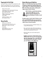
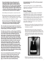
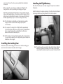
Ultra-Micro™ Sukhoi Su-26m BNF Instruction Manual ParkZone® products are distributed exclusively by Horizon Hobby, Inc. 4105 Fieldstone Road Champaign, IL 61822 © 2009 Horizon Hobby, Inc. Horizon Hobby UK Units 1-4, Ployters Road Staple Tye Harlow, Essex CM18 7NS United Kingdom Horizon Hobby Deutschland GmbH Hamburger Strasse 10 25335 Elmshorn Germany US Patent No. D578,146 Multiple patents pending DSM and DSM2 are trademarks or registered trademarks of Horizon Hobby, Inc. The Spektrum trademark is used with permission of Bachmann Industries, Inc. Futaba is a registered trademark of Futaba Denshi Kogyo Kabushiki Kaisha Corporation of Japan. www.parkzone.com 14667 Printed 3/09 Wingspan: 15.75 in (400mm) Length: 14.25 in (366mm) Weight: 1.1 oz (34 g) Motor: 8.5mm Brushed Motor Battery: 1S 3.7V 110mAh Lithium Polymer (included) Charger: 1S 3.7V DC Lithium Polymer Battery Charger (included) Transmitter: 5 + channel 2.4GHz with Spektrum DSM2 (required) On-Board Electronics: Spektrum AR6400 Ultra-Micro Receiver (SPMAR6400) and 1.5 g Linear Servo (SPMAS2000) 2 Sukhoi Su-26m Introduction Compatible with all Spektrum DSM2™ technology equipped transmitters and modules, the Sukhoi Su-26m Bind-N-Fly is an ultra-micro version of the Su-26m that offers true 4-channel aerobatic performance in an ultra-micro sized package. The Sukhoi Su-26m offers fully aerobatic flying and Spektrum 2.4GHz DSM2 control. With a flying weight of only 1.1 oz (34 g), the Sukhoi can be flown from a gym to your front yard without having to make a trip to the flying field. The Sukhoi is designed for experienced pilots that have previously flown 4-channel aircraft. The Sukhoi Su-26m comes 100% factory-assembled and is ready to bind to your Spektrum DSM2 equipped aircraft transmitter. Also included in the box is the lithium polymer flight battery and convienient AA battery-powered DC Li-Po battery charger, along with 4 AA batteries for the charger. The DSM2 technology offers freedom from frequency restrictions and allows the Sukhoi to be flown just about anywhere with full 4-channel control. Although the Sukhoi is nearly ready-to-fly right from the box, please take time to read through this manual for tips on battery safety and charging, binding, control setup and more before making your first flight. It is important that you only charge the included 3.7V 70mAh Li-Po battery (PKZ3001) with the included 1S 3.7V DC Li-Po Battery Charger (PKZ3240). You can also use the E-flite® Celectra™ 4-Port Charger (EFLC1004). This charger safely charges four 3.7V packs independently. Attempting to charge the battery using another Li-Po battery charger or non-Li-Po compatible charger could result in serious damage. Additional Safety Precautions and Warnings As the user of this product, you are solely responsible for operating in a manner that does not endanger yourself and others or result in damage to the product or the property of others. This model is controlled by a radio signal that is subject to interference from many sources outside your control. This interference can cause momentary loss of control so it is advisable to always keep a safe distance in all directions around your model, as this margin will help avoid collisions or injury. •Never operate your model with low transmitter batteries. •Always operate your model in an open area away from cars, traffic, or people. •Avoid operating your model in the street where injury or damage can occur. •Never operate the model in the street or in populated areas for any reason. •Carefully follow the directions and warnings for this and any optional support equipment (chargers, rechargeable battery packs, etc.) that you use. •Keep all chemicals, small parts and anything electrical out of the reach of children. •Moisture causes damage to electronics. Avoid water exposure to all equipment not specifically designed and protected for this purpose. •Never lick or place any portion of your model in your mouth as it could cause serious injury or even death. Sukhoi Su-26m BNF Contents Sukhoi BNF Airframe 1S 3.7V Li-Po Battery Charger, 0.3A 110mAh 1S 3.7V Li-Po Battery 4 x AA Batteries (for the charger) Landing Gear Additional Equipment A DSM2 compatible aircraft transmitter is required to complete your Sukhoi. 1 2 Preparing for the First Flight Battery Warnings and Guidelines Please note this checklist is not intended to be a replacement for the content included in this manual. Although it can be used as a quick start guide, we strongly suggest reading through this manual completely before proceeding. While the 1S 3.7V DC Lithium Polymer Battery Charger (PKZ3240) included with your Sukhoi has been specifically designed to safely charge the included 1S 3.7V 110mAh Li-Po Battery (PKZ1034), you MUST read the following safety instructions and warnings before handling, charging or using the Li-Po battery. •Remove and inspect contents •Install landing gear into the slot on the bottom of the fuselage •Install 4 AA batteries into the battery charger •Begin charging the flight battery •Bind the receiver to your chosen Spektrum or JR DSM2 equipped transmitter •Test the controls •Familiarize yourself with the controls •Find a suitable area for flying Flying Checklist •Always turn on the transmitter first •Plug the flight battery into the lead from the receiver •Allow the receiver to initialize and arm properly •Fly the model •Land the model •Unplug the flight battery from the receiver •Always turn off the transmitter last Note: Li-Po batteries are significantly more volatile than the alkaline, NiCd or NiMH batteries used in RC applications. All instructions and warnings must be followed exactly. Mishandling of Li-Po batteries can result in fire. By handling, charging or using the included Li-Po battery you assume all risks associated with lithium batteries. If you do not agree with these conditions, return your complete Sukhoi model in new, unused condition to the place of purchase immediately. • You must charge the included 1S 3.7V 110mAh Li-Po battery in a safe area away from flammable materials. • Never charge the battery unattended. When charging the battery you should always remain in constant observation to monitor the charging process and react to potential problems that may occur. • After flight, the battery must be cooled to ambient temperature before charging. • You MUST use the included 1S 3.7V DC Li-Po Battery Charger (PKZ3240). Failure to do so may result in a fire causing personal injury and/or property damage. You can use the E-flite Celectra 4-Port Charger (EFLC1004) to safely charge the 3.7V battery pack as well. DO NOT use a NiCd or NiMH charger. 3 4 • If at any time during the charge or discharge process the battery begins to balloon or swell, discontinue charging or discharging immediately. Quickly and safely disconnect the battery, then place it in a safe, open area away from flammable materials to observe it for at least 15 minutes. Continuing to charge or discharge a battery that has begun to balloon or swell can result in a fire. A battery that has ballooned or swollen even a small amount must be removed from service completely. discharging the battery to the soft LVC can still cause permanent damage to the battery. • Store the battery at room temperature in a dry area for best results. It is important that you only charge the included 1S 3.7V 110mAh Li-Po Battery (PKZ1034) with the included 1S 3.7V DC Li-Po Battery Charger (PKZ3240) or the previously mentioned E-flite Celectra 4-port Charger (EFLC1004). Attempting to charge the battery using another Li-Po charger or non-Li-Po compatible charger could result in serious damage. Please familiarize yourself thoroughly with the Battery Warnings and Guidelines section before continuing. Please follow these steps to charge the Li-Po battery with the included charger: • When transporting or temporarily storing the battery, the temperature range should be from 40–120 degrees Fahrenheit. Do not store the battery or model in a car or direct sunlight whenever possible. If stored in a hot car, the battery can be damaged or even catch fire. • Do not over-discharge the Li-Po flight battery. Discharging the battery too low can cause damage to the battery resulting in reduced power, duration or failure of the battery entirely. Li-Po cells should not be discharged to below 3V each under load. In the case of the 1S Li-Po battery used for the Sukhoi, you will not want to allow the battery to fall to below 3V during flight. The Sukhoi receiver unit features a soft low voltage cutoff (LVC) that occurs when the battery reaches 3V under load. When the soft cutoff occurs, the ESCs of the receiver unit will reduce power to the motor (regardless of the power level you have set with the throttle stick) in order to prevent the voltage of the battery from dropping below 3V. This reduction in power usually requires that you land the model immediately, at which point you should power down the model and unplug the flight battery. And while it is possible to power the model up and to fly again after the soft LVC occurs, this is NOT recommended as continued discharging to the soft LVC will cause permanent damage to the Li-Po battery that results in lost power and duration when using the battery for subsequent flights, or failure of the battery entirely. Continued attempts to further discharge the battery may also result in loss of control while the motor is running as the voltage of the battery may drop below the minimum operating voltage of the receiver and other electronics. Also, it is not recommended that you fly to the soft LVC every time you fly. Instead, you should be aware of the power level of the battery/airplane throughout the flight, and if at any time the airplane begins to require more throttle than typical to maintain flight, you should land the airplane immediately. Routinely 5 If you have any further questions or concerns regarding the handling, charging and/or use of the included Li-Po battery, please contact Horizon Support Team at 877-504-0233. Battery Charging • Remove the cover on the bottom of the charger and install four of the included AA batteries, noting proper polarity. Replace the cover after the AA batteries are installed. • Slide the battery into the slot on the charger. The endcap of the battery has been specifically designed to allow the battery to be slid into the slot easily one way (usually with the label on the battery facing outward) to prevent reverse polarity connection. However, please be sure to check for proper alignment and polarity before proceeding to the next step. • Gently press the battery and its connector into the charge jack/ connector located at the bottom of the slot in the charger. Again, be 6 sure to check for and to achieve proper polarity before making the connection. • After you make the connection successfully, the LED light on the charger will turn solid red, indicating that charging has begun. • It will take approximately 30–40 minutes to charge a fully discharged (not over-discharged) battery. As the battery nears full charge, the LED light will begin to blink. When the battery is fully charged the LED light will blink approximately every 20 seconds or will go out entirely. Installing the Flight Battery Once the Li-Po battery has been fully charged, it’s ready to be installed in the airplane. Install the battery in the airplane by placing it into the slot on the bottom of the fuselage with the plug facing toward the front of the airplane. Note: The Li-Po battery included with your Sukhoi will arrive partially charged. For this reason the initial charge may only take 15–20 minutes. Note: You can expect to charge the Li-Po flight battery approximately 15–20 times before it will be necessary to replace the AA batteries in the charger. Replacing the included batteries with alkaline batteries will extend the AA battery life. Note: If LED remains on for longer than 40 minutes while charging and/or 5 seconds after removing the Li-Po flight battery, please replace the AA batteries in the charger. Installing the Landing Gear Remove the airplane and landing gear from the box. Slide the landing gear wire into the slot located on the bottom of the fuselage. 7 Note: T he battery cavity is oversized to allow for the Center of Gravity adjustment. Start with the battery in the middle of the battery cavity. Adjust the battery forward or rearward to fine-tune the CG. 8 Transmitter and Receiver Binding Transmitter Specific Binding Instructions Binding is the process of programming the receiver of the control unit to recognize the GUID (Globally Unique Identifier) code of a single specific transmitter. It will be necessary for you to ‘bind’ your chosen Spektrum DSM2 technology equipped transmitter to the receiver for proper operation. DX5e: A. To bind your Sukhoi Su-26m to the DX5e, plug the battery into the receiver of the airplane. The LED on the receiver will begin flashing. B. Move the sticks and switches on the transmitter to the desired failsafe positions (low throttle and neutral control positions). C. Pull and hold the Trainer Switch on the transmitter while turning the transmitter on. Release the trainer switch once the LEDs on the front of the transmitter flash. D. The LED on the receiver will go solid red and the system will connect after several seconds. The following is a list of some of the Spektrum DSM2 equipped transmitters and modules that will bind to the receiver of the Sukhoi: Note: ParkZone recommends flying the fully aerobatic Sukhoi with a full size transmitter equipped with dual rates. E-flite HP6DSM Spektrum DX5e Spektrum DX6i Spektrum DX7 JR X9303 2.4 JR 12X 2.4 Compatible, but not recommended: ParkZone Vapor Transmitter E-flite LP5DSM E-flite MLP4DSM Note: The Spektrum DX6 (SPM2460) is equipped with DSM (not DSM2) technology and is not compatible with the receiver of the Sukhoi BNF. The following steps outline the binding process: • Confirm the process of entering the bind mode for your chosen transmitter by reviewing the instruction manual included with the transmitter. • Make sure the flight battery is disconnected from the receiver unit and the transmitter is turned off. • Plug the flight battery into the receiver unit. After 5 seconds the LED on the receiver unit will begin flashing. • After verifying the LED is flashing on the receiver, follow the steps that allow your chosen transmitter to enter bind mode. • If you entered bind mode correctly, you will see a solid LED approximately 5–10 seconds later on the receiver. You should now be bound to the transmitter, and have full control and function. If you encounter any problems, repeat the binding process again, see the trouble shooting guide or call the Horizon Support Team at 1-877-504-0233. 9 DX6i: A. To bind your Sukhoi Su-26m to the DX6i, plug the battery into the receiver of the airplane. The LED on the receiver will begin flashing. B. Move the sticks and switches on the transmitter to the desired failsafe positions (low throttle and neutral control positions). C. Pull and hold the Trainer Switch on the transmitter while turning the transmitter on. Release the trainer switch once the word BIND flashes on the LCD screen on the front of the transmitter. D. The LED on the receiver will go solid red and the system will connect after several seconds. DX7 (includes DX7se): A. To bind your Sukhoi Su-26m to the DX7, plug the battery into the receiver of the airplane. The LED on the receiver will begin flashing. B. Move the sticks and switches on the transmitter to the desired failsafe positions (low throttle and neutral control positions). C. Press the bind button on the back of the transmitter while turning the transmitter on. The bind button on the back of the transmitter will flash. Release the button after 2-3 seconds. D. The LED on the receiver will go solid red and the system will connect after several seconds. X9303: A. To bind your Sukhoi Su-26m to the X9303, plug the battery into the receiver of the airplane. The LED on the receiver will begin flashing. B. Move the sticks and switches on the transmitter to the desired failsafe positions (low throttle and neutral control positions). C. Press the bind button on the back of the transmitter while turning the transmitter on. The bind button on the back of the transmitter will flash. Release the button after 2-3 seconds. D. The LED on the receiver will go solid red and the system will connect after several seconds. 10 Transmitter Control Identification Note: Each time before you fly you should ALWAYS turn the transmitter on before connecting the flight battery to the receiver unit. After each flight, be sure that you always disconnect the flight battery from the receiver unit before powering the transmitter off. Additional Smartbind™ Information Prior to each flight, you should ensure that you power on your transmitter and wait about five seconds before you plug the flight battery into the receiver. Doing this allows time for the transmitter to scan and secure two open frequencies. If the flight battery is plugged in too quickly and the link is missed, it may cause the receiver to inadvertently enter bind mode. If this occurs simply leave the transmitter on and then disconnect and reconnect the flight battery. Control Test Although in most cases your transmitter of choice will offer full and proper control of the Sukhoi BNF with Spektrum/JR ‘standard’ settings (standard airplane mode, servo reversing set to normal and travel adjustments set to 100%), you must test the controls prior to the first flight to ensure none of the servos, linkages or parts were damaged during shipping and handling and that the controls function in the correct directions. Turn the transmitter on first and lower the throttle stick completely. Then, plug the battery into the battery lead of the receiver unit. Note: T he connectors on the battery and battery lead are keyed to prevent reverse polarity connection. However, if you force them together in the wrong orientation and with the wrong polarity it is still possible to damage the battery and/or receiver unit. To help further prevent a reverse polarity connection, one side of the endcap on the battery and the connector on the battery lead of the receiver unit will have a red dot. The connectors are oriented for a proper polarity connection when the red dots are on the same side. Move the elevator stick on the transmitter forward and aft to check elevator pitch control. When the stick is pushed forward, the elevator should move down. 11 12 When the elevator stick is moved aft the elevator should move up. Move the aileron stick left and right to check aileron roll control. When the stick is pushed to the left, the left aileron should move up and the right aileron should move down. 13 With the aileron stick pushed right, the right aileron should move up and the left aileron should move down. Move the rudder stick left and right to check yaw control. When the stick is pushed to the right the rudder should also move to the right (if viewed from behind the airplane). 14 With the rudder stick pushed to the left, the rudder should move to the left (if viewed from behind the airplane). Receiver Control Unit Description, Arming and Motor Control Test The Spektrum AR6400 installed on your Sukhoi is a lightweight combination of main motor electronic speed control, servos and Spektrum DSM2 compatible receiver. The receiver unit is also equipped with a status indicator LED. Please refer to the instruction manual of the AR6400 for more information on the unique features and programming options. The following checklist contains the steps you must follow to ensure proper arming and operation of the receiver unit, as well as proper motor response: • Each time before you fly you should ALWAYS turn the transmitter on before connecting the flight battery to the receiver unit. Never connect the flight battery to the receiver unit before powering the transmitter on first. After each flight, be sure that you always disconnect the flight battery from the receiver unit before powering the transmitter off. If at any time during the test the controls respond in the opposite direction, it may be necessary to reverse/change the direction of operation of the flight controls. Follow your transmitter instructions to change the direction of the various flight controls. Once you’ve reconfirmed the flight control directions, all controls should be functioning properly. However, if you continue to encounter any problems with your Sukhoi responding properly to the transmitter, do not fly. Call the Horizon Support Team at 1-877-504-0233. Note: P arkZone recommends setting Dual rates at 70% for first flights. Dual rates and expo (if available) can then be tuned to the pilots tastes. Note: T he only time you should connect the flight battery to the receiver unit before powering the transmitter on is when you are binding the receiver of the receiver unit to the transmitter. Please see the Transmitter and Receiver Binding section of this manual for more information. • The throttle stick MUST be set in the lowest possible position, and, for most transmitters, the throttle trim must also be set to the lowest possible position in order for the receiver unit to arm. If this is the first test flight, or a test flight following repairs, you should also center the rudder, aileron and elevator trims. • When the status LED on the AR6400 becomes solid red, the receiver unit is initialized and ready for flight. Also, as long as you had the throttle stick in the idle position and the throttle trim in the lowest position during the initialization process, the ESC/motor will now be armed. Use caution as the propeller will now spin with throttle stick input. Note: If the status LED of the AR6400 does not become solid red, please review the following: • If after blinking red the status LED becomes solid red, but you have no control of the motor, you have a positive Radio Frequency (RF) link between the transmitter and receiver, but the throttle stick and throttle trim may not be set to the correct positions. Check to be sure that the throttle stick is in the lowest possible position, and that the throttle trim is set to the middle or a lower-than-the-middle position. If you now have control of the motor, proceed to the next step of the checklist. 15 16 • If the blinking red status LED keeps flashing, you do not have a positive RF link between the transmitter and receiver. Check to be sure that the transmitter has been powered on and that the LED indicator on the transmitter is glowing solid red. If the transmitter is powered on and functioning properly, disconnect the flight battery from the receiver unit, then reconnect it. Now the receiver unit should initialize and arm properly. Stock Control Throw Aileron: 10mm up, 7mm down measured at widest point +/– 1mm Elevator: 10mm up, 10mm down measured at widest point +/– 1mm Rudder: 12mm left, 12mm right measured at widest point +/– 2mm CG Range: 29mm–31mm from leading edge of wing at the fuselage Note: In the event you inadvertently enter Bind Mode, the LED on the AR6400 will be flashing red continuously. If this occurs, cycle the flight battery while the transmitter is on (if previously bound). If your receiver unit will not initialize and arm after following the guidelines as listed above, call the Horizon Support Team at 1-877-504-0233. • Once you have placed the airplane in a safe area, free of obstructions, and are clear of the propeller, you can safely begin to power up the model to check for proper operation of the motor. • Advance the throttle stick upward slowly, just until the propeller begins to spin. DO NOT attempt to fly the airplane at this time. Note the direction the propeller spins. If viewed from the front of the airplane the propeller will spin counterclockwise. If it is spinning backwards, disconnect the battery and reverse the polarity of the motor’s input power leads. Note: After initial flights, the CG can be adjusted to the pilots preference. 17 18 Out of the box the ailerons are set at the lower travel setting on the aileron bellcrank. To increase the aileron travel, first cut through the decal on one side of the cowl. Cut through or pull off the tape behind the wing and on the turtle deck. Open the top of the airplane and locate the aileron bellcrank. To increase the aileron throw, gently pull up on the pushrod to disengage the pushrod from the outer hole and move to the inner hole on the bellcrank. Replace the tape on the fuselage on the cowl, behind the wing and on the turtle deck. The airplane is now set for maximum aileron throw using 100% ATV on the transmitter. To increase rudder and elevator throw, move the pushrods to the inner holes on the control horn one hole at a time and fly the airplane to get used to the increased throw of the control surfaces. Note: D o not set you transmitter ATV over 100%. If the ATV is set over 100% it is possible to overdrive the servo and cause damage to the servo. The servo pushrod is in the outer hole of the aileron bellcrank. Choosing a Flying Area When you are ready for your first flight, you will want to select a relatively open area, the size of a basketball court or larger, that is free of people and obstructions with calm wind (if flown outdoors). Once you have properly trimmed your airplane and become familiar with its handling and capabilities, you will be able to fly in other smaller, less open areas. 19 20 Flying the Sukhoi Having followed the proper receiver initialization and arming procedures, confirmed proper control of the servos and motor, and found a suitable flying area, your Sukhoi is ready for flight. Start first flight using the low rate settings to become familiar with the flying characteristics before increasing the throw of the control surfaces. Place the Sukhoi in position for takeoff (facing into the wind if flying outdoors). Gradually increase the throttle to ¾ to full, and steer with the rudder. Pull back gently with the elevator and climb to check trim. Once the plane is trimmed out, you can begin exploring the flight envelope of the Sukhoi. Note: Due to the large propeller on the Sukhoi, it is possible to hit the prop on the ground while landing. Make sure to flare when landing and try to land as smoothly as possible to minimize hitting the prop. While this does not damage the airplane it is possible to wear down the tips of the propeller if flying from an abrasive surface such as concrete or asphalt. • IN THE UNFORTUNATE EVENT OF A CRASH OR PROPELLER STRIKE, NO MATTER HOW MINOR OR MAJOR, YOU MUST LOWER THE THROTTLE STICK AND TRIM TO THEIR LOWEST POSSIBLE POSITIONS AS QUICKLY AS POSSIBLE TO PREVENT DAMAGE TO THE ESC OF THE RECEIVER UNIT. Failure to lower the throttle stick and trim to the lowest possible positions in the event of a crash could result in damage to the ESC in the receiver unit, which may require replacement of the receiver unit. Replacement Parts PKZ3502 PKZ3503 PKZ3506 PKZ3507 PKZ3516 PKZ3520 PKZ3522 PKZ3523 PKZ3524 PKZ3525 PKZ3527 PKZ3528 PKZ3567 PKZ1034 SPMAR6400 SPMAS2000 Prop with Spinner: Sukhoi Decal Sheet: Sukhoi Landing Gear: Sukhoi Tail Wheel: Sukhoi Motor: Sukhoi Wing with Ailerons: Sukhoi Aileron Pushrod and Linkages: Sukhoi Aileron Bellcrank: Sukhoi Complete Tail with Accessories: Sukhoi Elevator and Rudder Pushrod Set: Sukhoi Gearbox without Motor: Sukhoi Prop Shaft: Sukhoi Bare Fuselage: Sukhoi 3.7V 110mAh Li-Po Battery DSM2 6-Channel Ultra Micro Receiver w/ESC and Servos 1.5g Linear Servo Optional Parts PKZ3052 EFLC1004 EFLC1005 EFLB1101S SPM6825 Battery Connector with Wire E-flite Celectra 4-Port Charger 6V 1.5A AC Power Supply 3.7V 110mAh Li-Po Battery Linear Servo Reverser Note: Crash damage is not covered under warranty. 21 22 Trouble Shooting Guide z Problem Possible Cause Aircraft will not “throttle up” • User did not lower throttle trim and but all other controls seem to throttle stick prior to initializing the function. aircraft. • Throttle channel is reversed. Note: Futaba transmitters (equipped with Spektrum modules) may require you to reverse the throttle channel. Warranty Solution • Lower throttle stick and throttle trim to their lowest settings. • Reverse throttle channel on specific transmitter if applicable. Propeller or motor shaft broken. • Crash damage • Replace with PKZ3502 Prop with Spinner: Sukhoi, or PKZ3528 Prop Shaft: Sukhoi. Aircraft appears to show significant decrease in flight time. • Flight battery is not fully charged. • Recharge flight battery completely. • Replace AA batteries in the charger and recharge flight battery completely. • Replace PKZ1034 battery and read “Battery Warnings and Guidelines” section of manual. • Replace AA batteries in the charger. • AA batteries in charger have inadequate power. • PKZ1034 battery has been overdischarged multiple times, causing damage to battery life. Charger light stays on after • AA batteries in the charger have Li-Po battery is disconnected inadequate power. or remains on for longer than 40 minutes when charging. Aircraft appears to have less power. • Bushings on gearbox may be causing friction, reducing power. • Lubricate the bushings of the gearbox. LED on Aircraft remains flashing and cannot be controlled by transmitter. • User did not wait at least 5 seconds after powering the transmitter prior to connecting the flight battery to the Aircraft. • User bound the Aircraft to a different transmitter. • Unplug, then reconnect flight battery. • Transmitter was too close to Aircraft during the initialization process. • Rebind Aircraft to your desired compatible transmitter. • Move transmitter (powered on) a few feet from the Aircraft prior to reconnecting the flight battery. Aircraft appears to roll, yaw, or pitch towards a certain direction. • User did not re-trim the Aircraft. • Trim control surface using the transmitter until airplane no longer moves that direction. Controls appear to be reversed after binding to a different transmitter. • User did not initially set up their transmitter prior to binding to the Aircraft. • Read “Control Test” section of this manual. Pages 12–15. Aircraft does not function • User may have accidentally plugged after connecting flight battery the flight battery in the wrong polarity. and aircraft smells burnt. 23 • Replace AR6400 board (SPMAR6400) and ensure the RED polarity marks are facing the same direction when connecting the flight battery to the AR6400 board. Warranty Period Exclusive Warranty- Horizon Hobby, Inc., (Horizon) warranties that the Products purchased (the “Product”) will be free from defects in materials and workmanship at the date of purchase by the Purchaser. Limited Warranty (a) This warranty is limited to the original Purchaser (“Purchaser”) and is not transferable. REPAIR OR REPLACEMENT AS PROVIDED UNDER THIS WARRANTY IS THE EXCLUSIVE REMEDY OF THE PURCHASER. This warranty covers only those Products purchased from an authorized Horizon dealer. Third party transactions are not covered by this warranty. Proof of purchase is required for warranty claims. Further, Horizon reserves the right to change or modify this warranty without notice and disclaims all other warranties, express or implied. (b) Limitations- HORIZON MAKES NO WARRANTY OR REPRESENTATION, EXPRESS OR IMPLIED, ABOUT NON-INFRINGEMENT, MERCHANTABILITY OR FITNESS FOR A PARTICULAR PURPOSE OF THE PRODUCT. THE PURCHASER ACKNOWLEDGES THAT THEY ALONE HAVE DETERMINED THAT THE PRODUCT WILL SUITABLY MEET THE REQUIREMENTS OF THE PURCHASER’S INTENDED USE. (c) Purchaser Remedy- Horizon’s sole obligation hereunder shall be that Horizon will, at its option, (i) repair or (ii) replace, any Product determined by Horizon to be defective. In the event of a defect, these are the Purchaser’s exclusive remedies. Horizon reserves the right to inspect any and all equipment involved in a warranty claim. Repair or replacement decisions are at the sole discretion of Horizon. This warranty does not cover cosmetic damage or damage due to acts of God, accident, misuse, abuse, negligence, commercial use, or modification of or to any part of the Product. This warranty does not cover damage due to improper installation, operation, maintenance, or attempted repair by anyone other than Horizon. Return of any goods by Purchaser must be approved in writing by Horizon before shipment. Damage Limits HORIZON SHALL NOT BE LIABLE FOR SPECIAL, INDIRECT OR CONSEQUENTIAL DAMAGES, LOSS OF PROFITS OR PRODUCTION OR COMMERCIAL LOSS IN ANY WAY CONNECTED WITH THE PRODUCT, WHETHER SUCH CLAIM IS BASED IN CONTRACT, WARRANTY, NEGLIGENCE, OR STRICT LIABILITY. Further, in no event shall the liability of Horizon exceed the individual price of the Product on which liability is asserted. As Horizon 24 has no control over use, setup, final assembly, modification or misuse, no liability shall be assumed nor accepted for any resulting damage or injury. By the act of use, setup or assembly, the user accepts all resulting liability. If you as the Purchaser or user are not prepared to accept the liability associated with the use of this Product, you are advised to return this Product immediately in new and unused condition to the place of purchase. Law: These Terms are governed by Illinois law (without regard to conflict of law principals). Safety Precautions This is a sophisticated hobby Product and not a toy. It must be operated with caution and common sense and requires some basic mechanical ability. Failure to operate this Product in a safe and responsible manner could result in injury or damage to the Product or other property. This Product is not intended for use by children without direct adult supervision. The Product manual contains instructions for safety, operation and maintenance. It is essential to read and follow all the instructions and warnings in the manual, prior to assembly, setup or use, in order to operate correctly and avoid damage or injury. Questions, Assistance, and Repairs Your local hobby store and/or place of purchase cannot provide warranty support or repair. Once assembly, setup or use of the Product has been started, you must contact Horizon directly. This will enable Horizon to better answer your questions and service you in the event that you may need any assistance. For questions or assistance, please direct your email to [email protected], or call 877.504.0233 toll free to speak to a service technician. Inspection or Repairs If this Product needs to be inspected or repaired, please call for a Return Merchandise Authorization (RMA). Pack the Product securely using a shipping carton. Please note that original boxes may be included, but are not designed to withstand the rigors of shipping without additional protection. Ship via a carrier that provides tracking and insurance for lost or damaged parcels, as Horizon is not responsible for merchandise until it arrives and is accepted at our facility. A Service Repair Request is available at www.horizonhobby. com on the “Support” tab. If you do not have internet access, please include a letter with your complete name, street address, email address and phone number where you can be reached during business days, your RMA number, a list of the included items, method of payment for any non-warranty expenses and a brief summary of the problem. Your original sales receipt must also be 25 included for warranty consideration. Be sure your name, address, and RMA number are clearly written on the outside of the shipping carton. Warranty Inspection and Repairs To receive warranty service, you must include your original sales receipt verifying the proof-of-purchase date. Provided warranty conditions have been met, your Product will be repaired or replaced free of charge. Repair or replacement decisions are at the sole discretion of Horizon Hobby. Non-Warranty Repairs Should your repair not be covered by warranty the repair will be completed and payment will be required without notification or estimate of the expense unless the expense exceeds 50% of the retail purchase cost. By submitting the item for repair you are agreeing to payment of the repair without notification. Repair estimates are available upon request. You must include this request with your repair. Non-warranty repair estimates will be billed a minimum of ½ hour of labor. In addition you will be billed for return freight. Please advise us of your preferred method of payment. Horizon accepts money orders and cashiers checks, as well as Visa, MasterCard, American Express, and Discover cards. If you choose to pay by credit card, please include your credit card number and expiration date. Any repair left unpaid or unclaimed after 90 days will be considered abandoned and will be disposed of accordingly. Please note: non-warranty repair is only available on electronics and model engines. United States Electronics and engines requiring inspection or repair should be shipped to the following address: Horizon Service Center 4105 Fieldstone Road Champaign, Illinois 61822 All other Products requiring warranty inspection or repair should be shipped to the following address: Horizon Product Support 4105 Fieldstone Road Champaign, Illinois 61822 Please call 877-504-0233 or e-mail us at [email protected] with any questions or concerns regarding this product or warranty. 26 United Kingdom Electronics and engines requiring inspection or repair should be shipped to the following address: Horizon Hobby UK Units 1-4 Ployters Rd Staple Tye Harlow, Essex CM18 7NS United Kingdom Please call +44 (0) 1279 641 097 or e-mail us at [email protected] with any questions or concerns regarding this product or warranty. Germany Electronics and engines requiring inspection or repair should be shipped to the following address: Horizon Technischer Service Hamburger Strasse 10 25335 Elmshorn Germany Please call +49 4121 46199 66 or e-mail us at [email protected] with any questions or concerns regarding this product or warranty. Product Registration Register your product online at: http://www.parkzone.com/register/ E Compliance Information for the C European Union Instructions for Disposal of WEEE by Users in the European Union This product must not be disposed of with other waste. Instead, it is the user’s responsibility to dispose of their waste equipment by handing it over to a designated collections point for the recycling of waste electrical and electronic equipment. The separate collection and recycling of your waste equipment at the time of disposal Declaration of Conformity (in accordance with ISO/IEC 17050-1) No. HH2009040202 Product(s): Item Number(s): Equipment class: Micro Sukhoi Plane PKZ3580 1 The objects of declaration described above are in conformity with the requirements of the specifications listed below, following the provisions of the European R&TTE directive 1999/5/EC: EN 301 489-1 v.1.6.1 General EMC requirements for Radio equipment EN 301 489-17 v.1.2.1 Signed for and on behalf of: Horizon Hobby, Inc. Champaign, IL USA Apr 02, 2009 27 Steven A. Hall Vice President International Operations and Risk Management Horizon Hobby, Inc. 28