1
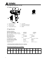
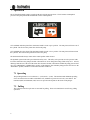
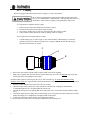
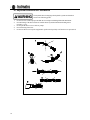
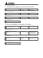
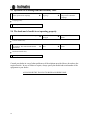
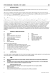
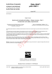
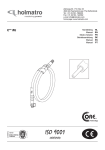
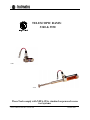
TELESCOPIC RAMS:
3340 & 3350
3340
3350
These Tools comply with NFPA-1936, standard on powered rescue
tool systems.
Owner’s Manual: Part No. 918.269.105
October 2002
All rights reserved. You are prohibited from copying or reproducing this manual, any
materials contained herein or any portion hereof in any manner whatsoever without the
express prior written consent of Holmatro.
Holmatro reserves the right to change the contents of this manual at any time without
prior notice. Holmatro also reserves the right to change any part or component of any
machine referenced in this manual at any time without prior notice.
This manual is intended for use solely with the basic version of each piece of
equipment and each product referenced and should not be used in connection with any
modified, altered or adapted version of any piece of equipment without the express prior
written consent of Holmatro.
Additional information on adjustments, maintenance and repair of any product
contained herein will be provided upon written request of the technical department of
your supplier. If not provided, contact Holmatro directly.
EXCEPT AS EXPRESSLY SET FORTH ON THE ENCLOSED WARRANTY
CARD, HOLMATRO MAKES NO OTHER WARRANTY OR
REPRESENTATION, EITHER EXPRESS OR IMPLIED, WITH RESPECT TO
THE STATEMENTS CONTAINED HEREIN. HOLMATRO HEREBY
EXCLUDES ANY AND ALL IMPLIED WARRANTIES, INCLUDING
WARRANTIES OF MERCHANTABILITY AND FITNESS FOR A
PARTICULAR PURPOSE.
IN NO EVENT WILL HOLMATRO BE LIABLE FOR DIRECT, INDIRECT,
SPECIAL, INCIDENTAL OR CONSEQUENTIAL DAMAGES ARISING OUT OF
USE OF THIS MANUAL OR ANY STATEMENTS CONTAINED THEREIN.
SOME STATES DO NOT ALLOW THE EXCLUSION OF IMPLIED
WARRANTIES OR LIABILITY FOR INCIDENTAL OR CONSEQUENTIAL
DAMAGES, SO THE ABOVE LIMITATION OR EXCLUSION MAY NOT
APPLY TO YOU.
IF ANY PROVISION CONTAINED HEREIN SHALL BE UNLAWFUL, VOID
OR FOR ANY REASON UNENFORCEABLE, THEN THAT PROVISION
SHALL BE SEVERED FROM THE STATEMENT AND SHALL NOT AFFECT
THE VALIDITY AND ENFORCEABILITY OF THE REMAINING
STATEMENTS CONTAINED HEREIN.
1
1. Introduction
We congratulate you on this purchase. Be sure to read and understand this user manual before using the tool. This
user manual covers the basic aspects for the safe use and operation of this equipment.
First of all check that your equipment is complete and undamaged. Notify your Holmatro dealer immediately if the
equipment is damaged or incomplete, and do not use the equipment.
This equipment is designed for use by professional, fully trained fire and rescue personnel.
This is a double-acting hydraulic tool designed to be driven only by a Holmatro hydraulic pump. The entire system
operates with mineral oil hydraulic fluid to an allowable pressure of 720 bar.
Follow these instructions to ensure your safety and to keep your equipment in good condition.
2. Safety Symbols
THIS IS THE SAFETY ALERT SYMBOL. IT IS USED TO ALERT YOU TO POTENTIAL
PERSONAL INJURY HAZARDS. OBEY ALL SAFETY MESSAGES THAT FOLLOW THIS
SYMBOL TO AVOID POSSIBLE INJURY OR DEATH.
DANGER indicates an imminently hazardous situation which, if not
avoided, will result in death or serious injury.
WARNING indicates a potentially hazardous situation which, if not avoided,
could result in death or serious injury.
CAUTION indicates a potentially hazardous situation which, if not avoided,
may result in minor or moderate injury.
CAUTION used without the safety alert symbol indicates a potentially
hazardous situation which, if not avoided, may result in property damage
2
3. Safety Instructions
Study these operating instructions carefully before operating this equipment.
*
*
*
*
*
*
*
*
*
*
*
*
*
*
*
*
*
*
*
*
Study these operating instructions carefully before operating this equipment.
Use this equipment only for jobs for which it is designed. If in doubt or unsure, be sure to consult your dealer.
Always wear personal protection equipment such as safety goggles, helmet, gloves, protective clothing and
safety shoes.
Keep spectators at sufficient distance.
Stand on stable ground and use both hands to hold and/or operate the equipment.
Hold the equipment only at the appropriate places, i.e. at the deadman's handle and the carrying handle.
Stabilize the objects the tool will be used on.
Ensure that the load is always applied to the centre of the cross heads and prevent angular loads.
Allow only the cross heads of the ram to come into contact with the objects to be moved.
Ensure that the dead-man's handle does not come in contact with firm objects. Stop in time!
In the event of oil leakage, stop immediately and consult the troubleshooting list.
In the event of unfamiliar noise, vibration or other unusual behaviour, stop immediately and consult your dealer.
Never disconnect the quick-action couplings when the pump is in operation and when the pressure relief valve
of the pump is in the "Operation" position.
Store the ram with its piston(s) slightly projecting. To do this, first close the pistons completely, then open one
section slightly.
Use only original Holmatro accessories and parts.
Observe the maintenance instructions.
Only trained service technicians certified by Holmatro are allowed to repair this equipment.
Replace safety symbols/pictograms and/or information labels if illegible.
The safety valves between the couplers must never be adjusted. In the event that a problem develops with the
safety valve, contact your dealer.
This equipment must only be operated with non-toxic mineral base hydraulic oil distributed by Holmatro.
4. Legend of symbols/warnings used on labels/stickers:
-
Wear personal protection equipment
Dead-man's handle operating direction
Product identification: model, serial number, year of construction, etc.
Warning: "Center the load"
Warning: "Never work under/between the load".
3
5. Description: model HTR3340
5.1 Product identification
A.
B.
C.
D.
Quick-action couplings
Safety relief valve
Dead-man's handle
Carrying handle (option)
E. Cross heads
F. Small Piston (2nd Section)
G. Large Piston ( 1st Section)
H. Cylinder
5.2 Specifications
Ram model: HTR3340
Allowable operating pressure
Max. Force (NFPA-1936 HSF) 1 st Section*
Max. Force (NFPA-1936 HSF) 2 nd Section**
Max. spreading travel
:
Piston length 1st Section
Piston length 2nd Section
Weight, ready for use
:
Closed Dimensions (LxWxH)
Oil volume required for opening
Oil volume required for closing
Net required oil volume
Temperature range
:
10,500 psi
(720 bar)
:
49,145 lbs
(218.6 kN)
:
18,210 lbs
(81 kN)
11 inches
(279 mm)
:
6 1/8 inches
(155 mm)
:
4 7/8 inches
(124 mm)
27 lbs
(12 kg)
:
12” x 16.5” x 6 1/8”
(305 x 420 x 155 mm)
:
38 cu in
(628 cc)
:
7.5 cu in
(124 cc)
:
30.5 cu in
(504 cc)
:
-4 F° to + 176° F
(-20 °C to +80 °C)
* The maximum (HSF) and minimum (LSF) forces are equivalent.
** The maximum (HSF) and minimum (LSF) forces are equivalent.
Opening and closing times (sec.) for HTR3340.
Open
2032
Close
3340 29
2035
GU
17
2035
PU
15
2035
EPA
15
2060
B&S
14
2060 2060 PPU15 DPU60 DPU60 DPU60
Honda GU
B&S Honda
E
14
15
15
18
13
9
13
14
14
13
13
The times shown are for opening & closing under no load.
4
14
18
18
13
13
15
6. Description: model HTR3350
6.1 Product identification
A.
B.
C.
D.
Quick-action couplings
Safety relief valve
Dead-man's handle
Carrying handle (option)
E. Cross heads
F. Small Piston (2nd Section)
G. Large Piston ( 1st Section)
H. Cylinder
6.2 Specifications
Ram model: HTR3350
Allowable operating pressure
Max. Force (NFPA-1936 HSF) 1 st Section*
Max. Force (NFPA-1936 HSF) 2 nd Section**
Max. spreading travel
:
Piston length 1st Section
Piston length 2nd Section
Weight, ready for use
:
Closed Dimensions (LxWxH)
Oil volume required for opening
Oil volume required for closing
Net required oil volume
Temperature range
:
10,500 psi
(720 bar)
:
49,145 lbs
(218.6 kN)
:
18,210 lbs
(81 kN)
29.25 inches
(743 mm)
:
15.25 inches
(387 mm)
:
14 inches
(356 mm)
40 lbs
(18 kg)
:
21” x 16.5” x 6 1/8”
(533 x 420 x 155 mm)
:
96.4 cu in
(1580 cc)
:
18.9 cu in
(310 cc)
:
77.5 cu in
(1270 cc)
:
-4 F° to + 176° F
(-20 °C to + 80 °C)
* The maximum (HSF) and minimum (LSF) forces are equivalent.
** The maximum (HSF) and minimum (LSF) forces are equivalent.
Opening and closing times (sec.) for HTR3350.
Open
2032
Close
3350 75
2035
GU
40
2035
PU
39
2035
EPA
39
2060
B&S
34
2060 2060 PPU15 DPU60 DPU60 DPU60
Honda GU
B&S Honda
E
35
37.5
21
32
34
34
31
32
The times shown are for opening & closing under no load.
37
44
44
32
34
44
35
34
34
5
7. Operation
The oil from the hydraulic pump is supplied to the unit via high-pressure hoses. The oil returns at atmospheric
pressure to the pump if the dead-man's handle is in the neutral position.
Fig. 1. Control handle label.
Oil is admitted under the piston if the dead-man's handle is in the “open” position. The ram pistons will move out of
the cylinder. The oil above the piston flows back to the pump.
Oil is admitted above the piston if the dead-man's handle is in the “close” position. The ram pistons will retract into
the cylinders. The oil below the piston flows back to the pump.
The dead-man's handle always returns to the neutral position when released.
The hydraulic system in the unit is provided with a safety valve. This safety valve prevents excessive pressure in the
tool if the return line to the pump is blocked or disconnected. Never change the setting of this safety valve. Oil will
discharge from the rear of the tool if the return hose becomes blocked or disconnected while the pump pressure relief
valve is in “PRESSURE”/”OPERATION” position. If this happens, first switch the pump pressure relief valve to the
“NEUTRAL” position, and then re-connect the return hose of the tool.
7.1 Spreading
The spreading distance is no less than 29 ¼” (3350) and 11” (3340). The maximum and minimum spreading
forces are measured in accordance with NFPA-1936, standard on powered rescue tools, 1999 edition. The
maximum (HSF) and minimum (LSF) forces are equivalent at all points on the stroke of the plunger.
7.2 Pulling
The 3340 and 3350 telescopic rams are not rated for pulling. These tools should not be used for any pulling
operations.
6
8. Use
8.1 Initial use (first time only)
*
*
*
Check the equipment for damage. Do not use the equipment if it is not in good condition. Notify your
dealer.
Check whether the guarantee registration card has been supplied and filled in.
Check whether the accessories are correctly mounted.
8.2 Preparation for use
*
Check the operation of the dead-man's handle (return to neutral position).
7
8.2.1
Coupling
The unit is equipped with different quick-action couplings, i.e. "male" and "female".
Never connect or disconnect the quick-action coupling when the pump relief
valve is set to “PRESSURE”/ “OPERATION”/”. Set the pump relief valve to its
"NEUTRAL" position before coupling or uncoupling hoses and/or tools.
To couple the hoses using the flat face coupler:
1.
2.
3.
4.
Remove the dust caps from both the male and female couplers.
Insert the male coupler into the female coupler and push.
The coupler’s locking ring (A) will move forward to show the coupler is locked.
Check to make sure the connection is made by pulling on the two couplers.
To uncouple the hoses using the flat face coupler:
1.
Turn the locking ring (A) of the coupler ¼ turn counterclockwise when holding it in your hand
pointing away from you (direction of large arrow on coupler) and pull back on the locking ring
(direction of small arrow on coupler).
C
A
B
2.
3.
Remove the male coupler from the female coupler if it has not released completely.
Make sure you put the dust caps back onto the couplers when not in use. This is an important step to keep dirt
and foreign objects from getting into the coupler.
Clean the female coupler by removing any dirt, oil, etc. with a clean dry rag. To ensure the automatic locking
capability of the coupler, the coupler should be checked periodically and cleaned by following the simple steps below:
1.
2.
3.
4.
5.
6.
8
Rinse the coupler with lukewarm water and a soft soap solution.
When the coupler is dry and free from water, lubricate the flat end of the coupling (B) with Holmatro
recommended hydraulic oil or by spraying WD-40 onto the end.
Lubricate the locking sleeve by spraying WD-40 carefully in the area (C) between the back part and the locking
sleeve.
Connect the nipple into the coupling and see if the locking sleeve easily turns itself to the lock position. Check by
pulling the locking sleeve straight back. The nipple should not disconnect.
To disconnect the nipple, turn the locking sleeve and pull it backward.
Repeat steps 4 and 5 a few times to assist internal lubrication of the locking sleeve.
8.2.2
Use
Turning the dead-man's handle clockwise has the same result in all Holmatro equipment (from 01.01.95):
the functional parts are opened. The functional parts are closed by turning counter-clockwise. As soon as
the dead-man's handle is released it automatically returns to its neutral position and the unit stops
operating immediately.
8.2.3
Spreading:
Ensure that the original crossheads are attached correctly.
The pistons are extended by turning the dead-man's handle clockwise and objects can be pushed apart. The
pump automatically supplies the required pressure as soon as the cross heads experience any resistance.
Prevent sharp protrusions from touching the piston during spreading.
Damage leads to leakage through the seal.
Prevent the cross heads from sliding from the load. Use the optional ram
support for weakened car bodies (see accessories section). Use only
original Holmatro accessories and attach them correctly.
8.2.4
Shutting down
On completion of the work retract the pistons back into the cylinders. Check that the pump relief valve is in
its "neutral" position before uncoupling. Remove any dirt from the couplings and the dust caps to prevent
penetration into the hydraulic system. Take the dust caps apart and place them on the tool’s couplings.
When the retracting movement stops, spread the pistons again over a
small distance of approx. 1/4 inch to relieve any pressure in the tool and
store the tool in that condition.
8.2.5
Cleaning and storage
Clean the unit and any accessories used before storage.
*
Clean all quick-action couplings. Ensure that the dust caps are installed.
*
Check the tool for external damage and/or oil leakage.
*
Check the operation of the dead-man's handle.
*
Dry the unit if it has been used in wet conditions. Lightly oil the steel parts.
*
Clean the tool with a mild soap solution and dry thoroughly.
9
8.3 Important additional user information
The hydraulic hoses belonging to the hydraulic system need attention.
Observe the following points:
1.
2.
3.
4.
5.
10
Do not use hoses without proper anti-kink devices and prevent kinking behind the attachment.
Prevent kinking of the hoses and never bend the hoses beyond their minimum bending radius
(89 mm) (3 ½ in).
Do not pull the hoses to move tools or pumps.
Prevent twisting of the hose.
Do not use the hoses to keep the equipment in position and especially not if the hoses are pressurized.
9. Troubleshooting
9.1 The quick-action couplings cannot be connected or disconnected.
1
è
2
è
3
Check tool control handle position
è
Handle in open or
close position
è
Release control handle to
neutral position
Control handle in neutral
Check for any pressure in the system
è
System pressurized
è
Release pressure at the pump
Pressure relieved
Check the coupling locking ring location
è
Incorrect position
è
Release locking ring
è
Locking ring released
4 Consult your Dealer
9.2 The connected equipment is not operating - or not properly.
1 Check the pump hydraulic oil level.
è
2
è
No or low hydraulic
fluid
è
Add recommended hydraulic
fluid up correct level.
Hydraulic fluid level correct
Check the connections (quick-action
couplings).
Incorrect coupling.
è
è
Release pressure at pump by
switching handle to the
“NEUTRAL” position.
Reconnect the couplings.
è
Couplings correct
Check the position of the pump pressure
3 relief valve.
è
Valve in
“NEUTRAL”.
position.
è
Turn valve to
“OPERATION” position.
è
Valve position okay
4 Consult your Dealer
11
9.3 Hydraulic oil is leaking from the tool safety valve.
1 Check quick-action couplings
è
Loose or disconnected
couplings
è
è
Relieve the pressure at the
pump and re-connect the
couplings.
è
Contact your Holmatro
Dealer
Couplings okay
2 Consult your Dealer
9.4 The dead-man’s handle is not operating properly.
1
Check control handle for external damage
è
Control handle
damaged
è
Control handle okay
Check if the dead-man handle is stuck in
2 any position. The control handle should
move freely.
è
Dead-man handle
stuck
è
Contact your Holmatro
Dealer
è
Dead-man handle okay.
3 Consult your Holmatro Dealer
Consult your dealer in case of other problems or if the solutions provided above do not have the
required results. In case of failure or repairs, always specify the model and serial number of the
equipment to your dealer.
ALWAYS SHIP THE TOOL IN ITS ORIGINAL SHIPPING BOX.
12
10. Maintenance
Wear personal protection equipment during maintenance. Ensure that any spent
replaced hydraulic oil is collected and disposed of in a responsible manner, think of
the environment.
10.1
Regular maintenance (minimum every 3 months)
It is necessary to carry out regular maintenance. Increased use will necessitate more frequent maintenance
intervals. Consult your dealer.
*
Check whether the safety symbols and product identification labels are still present. If not, consult your
dealer.
*
Check the functions of the dead-man's handle.
*
Check the accessories.
*
Check the hoses, quick-action couplings and dust caps.
*
Check the operation of the equipment.
10.2
Annual maintenance
With the proper care and correct preventive maintenance this unit will ensure many years of safe use. We
recommend having the unit checked at least once a year by a trained technician with the proper knowledge and
the necessary tools. Your dealer can carry out the annual maintenance on a contract basis on your behalf, if
desired. This will ensure good and safe operation.
10.3
Five yearly maintenance and testing
We advise you to have the equipment checked and tested by your dealer or other body certified by Holmatro
after a maximum of five years of use. Consult your dealer for further details.
10.4
*
*
Long-term storage
Ensure that the equipment is completely depressurized.
Store the equipment in a dry, well-ventilated area. Use additional preservatives on the external steel parts.
11. Scrapping
The unit can be scrapped at the end of its service life and the various parts may be recycled. Collect the hydraulic oil
and dispose of it separately. The unit consists of steel, aluminium, neoprene (seals) and plastic. The unit does not
contain any pressurized components.
Also, consult your dealer about scrapping.
13
12. Accessories
Two cross heads are supplied as standard with every unit. Additional accessories may be ordered, if required. Contact
your Holmatro Dealer for details.
Carrying handle
The Holmatro telescopic ram you have purchased comes with an optional carrying handle. If your fire department or
rescue company desires, the handle can be installed with ease. The handle is not installed at the factory, because some
rescuers may feel that the handle takes up too much space when working in confined areas. To install the handle
complete the following steps: (See diagram below)
1. Make sure the handle kit is complete. The kit includes:
1. two flat head attachment screws
2. two end pieces
3. one black aluminum rod
4. one Allen wrench
2. Insert the black aluminum rod into the end pieces. This is a snug fit, the use of a rubber mallet may be required.
3. Attach the end pieces to the ram using the two flat head screws as shown in the figure below. The holes for the
screws are already drilled and threaded into the body of the ram. The use of glue on the screws is not needed;
however, if desired glue can be used. A NON permanent loctite is recommended.
4. Tighten the screws into the ram until they are snug. Be careful not to over tighten.
14
13. Technical information
HTR3340/3350.
Made in the USA
The model 3340 and 3350 telescopic rams are not designed to be used as jacks and
should never be used as such. Never work under a load lifted by the model 3340
or 3350 telescopic ram. To safely lift a load, you may use Holmatro’s air lifting
bag. Properly chock the load before lifting.
Qualified persons authorized by Holmatro may only make repairs and/or service to Holmatro® rescue tools. An
active and presently authorized Holmatro dealer may only disassemble the sealed parts. Contact your dealer for
further advice if other problems occur. In the event that you are unable to contact your dealer, contact Holmatro at:
Holmatro, Inc.
505 McCormick Dr.
Glen Burnie, MD 21061
Fax: (410) 768-4878
Tel: (410) 768-9662
E-mail: [email protected]
Website: www.holmatro-usa.com
15
HOLMATRO DEALER:
TOOL MODEL NUMBER:
SERVICE RECORD:
DATE
TEL:
FAX:
TOOL SERIAL NUMBER:
REPAIR/SERVICE
DESCRIPTION
Please make copies of this sheet as needed for future use.
16
SERVICE
TECHNICIAN