1
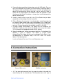
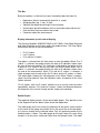
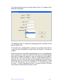
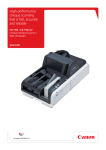
! "#
$%
& '
( )
*!
+
,-
! "#
$%
Contents
1. Introduction ............................................................................. 2
2. Technical Support ................................................................... 3
3. Equipment List ........................................................................ 3
4. Safety Instructions................................................................... 4
5. Installation............................................................................... 4
6. Connection Instructions........................................................... 5
7. Care and Handling .................................................................. 6
8. Starting the program................................................................ 7
9. Basic step by step procedure .................................................. 8
10.
Menus and Toolbar .............................................................. 9
10.1
File menu.................................................................................................................. 9
10.2
Measure menu ....................................................................................................... 10
10.3
View Menu.............................................................................................................. 10
10.4
Tools menu............................................................................................................. 11
11.
Options............................................................................... 11
12.
Data Analysis Screens ....................................................... 13
12.1
Primary Display ...................................................................................................... 13
12.2
Split Screen Display ............................................................................................... 18
13.
Dynamic Measurement ...................................................... 18
13.1
Dynamic measurement in free stroking mode, i.e. not making cans ..................... 18
13.2
Dynamic measurement when making cans ........................................................... 21
14.
Saving and Loading ........................................................... 22
15.
Static Measurement ........................................................... 24
16.
Calibration.......................................................................... 26
16.1
Calibration Cradle Alignment ................................................................................. 30
17.
Set-up ................................................................................ 32
18.
Expert System.................................................................... 38
-1-
1. Introduction
Photograph shows gauge ring to
suit 8 inch diameter tool-pack.
The Free Stroke Analyser is a tool for the measurement of punch sleeve, ram,
tool-pack/die and dome station alignment in 2-piece can bodymaker
machines. The equipment comprises precision gauge equipment as well as
specialised software. Its main function is to make measurements dynamically,
i.e. with the bodymaker running in continuous mode, but it can also be used to
measure the alignment statically.
There are several advantages in being able to measure the alignment
dynamically. The most important perhaps is the fact that the alignment can be
quite different when the bodymaker is running. Essentially, the dynamic
measurement allows the user to see exactly where the punch and ram are
going.
The Free Stroke Analyser gauge ring, which is fitted with non-contact
inductive sensors, is placed in the tool-pack. The bodymaker is run without
feeding in cups, i.e. in a free stroking mode, hence the name. This is in order
to measure the natural path of the ram, i.e. the path the ram takes when not
making cans and being forced through the centre of the dies. It is also
possible, however, to obtain measurements whilst making cans. Such
measurements can provide useful extra information.
The dynamic measurement not only reveals the misalignment of the tool-pack,
but of the dome station as well. This is done by measuring the deflection of
the ram as the punch nose enters the dome station.
-2-
The benefits that the Free Stroke Analyser can provide, include:
•
•
•
•
•
•
•
More effective maintenance
Tooling life
Can quality (e.g. fewer split domes)
Fewer bodymaker stoppages
Fewer stoppages further down the line caused by poor can quality
Spoilage
Lightweighting programs can also be greatly assisted by its use.
2. Technical Support
Should you experience any problems with the Free Stroke Analyser or require
any assistance in using it, please contact David Harvey either by phone or
email. Software updates and the manual can be downloaded from the
website.
Telephone contact number: +44 (0)7941 446553
E-mail Address: [email protected]
Website: www.deltahtechnology.co.uk
3. Equipment List
•
Gauge Ring or Rings
•
Calibration Cradle/s (optional)
•
Data-acquisition interface box
•
PCMCIA card and cable
•
USB cable
•
Interface box and power supply
•
Storage/carry case
•
CD ROM containing licensed copy of Free Stroke Analyser software
•
User’s Manual
•
Computer - Windows 8 or earlier, minimum 256MB ram. (Windows XP
OR (prior to April 2011)
with PCMCIA slot if PCMCIA card is being used)
-3-
4. Safety Instructions
•
Make certain that the gauge ring and the other items in the tool-pack are
correctly inserted so as not to obstruct the punch sleeve and ram.
•
Never run the bodymaker with a partially filled tool-pack cradle. The gauge
rings are made a convenient thickness such that it can replace a part of
the normal tool-pack, normally an ironing die. The items in a partially filled
tool-pack cradle are not held securely enough and could fall or be knocked
into the path of the ram causing a catastrophic crash.
•
Great care must be taken when using the gauge ring to make static
alignment measurements if the tool-pack cradle is not full and/or the lid is
open. Never place fingers in the tool-pack whilst barring or inching the
ram.
•
Take care with the electrical cables, especially the power cables, which
carry mains voltage. The gauge ring cable only has low voltage signals so
does not present an electrical safety risk.
•
The gauge ring and calibration cradle are heavy pieces of equipment with
some sharp edges and corners, so care should be taken with handling
and carrying.
5. Installation
1. Insert the CDROM.
2. Run the batch file “Install FSA”. (For installing onto a shared drive, copy
the fsa.exe, pccgo32.dll and cbw32.dll files to the desired location. Data
files can be copied onto the hard drive or a shared drive. Ensure that the
location of the database as given in “Options” is set to the correct location).
Steps 3 to 8 are only required if the device drivers need to be installed (i.e. not
if loading onto a shared drive).
3. Run the icalsetup.exe from the CDROM. Follow on screen instructions to
install the software drivers. (If you have an old model with a PCMCIA card,
run pccardgo.exe instead).
-4-
4. Connect the data-acquisition interface box using the USB cable. Then run
the InstaCal program that will be in the Measurement Computing folder in
All Programs from the Windows Start menu. InstaCal will automatically
detect the data-acquisition device and add it to the config file. Note, in
Options of the FSA program, the hardware should be selected as USB
interface and the Board # should be as shown when InstaCal detected the
device (normally zero).
5. Create a shortcut to the fsa.exe file in the C:\Free Stroke Analyser folder
and put this on the desktop. Run the fsa.exe file.
6. Click on Setup on the menu bar. If not already done, name the gauge ring
by selecting <New Gauge Ring> from the drop down list for ‘Gauge Ring’
in the Set-Up file. Give a name to identify the Gauge Ring (for example, if
you have 2 sizes of gauge ring they could be named 211 and 202).
7. To begin making measurements, the gauge must be calibrated (the
Calibration Cradle may also need to be aligned) and a set-up file created.
This is covered in the appropriate sections of this manual.
8. Setup the database for storing measurement data files. The location of the
database is given in “Options”. The default is “C:\Free Stroke
Analyser\Data Files” folder, but this can be changed. Define Plants, Lines
and Bodymakers in “Database Setup” in the “File” menu. This creates
folders in the following form:
Location of Database\’Plant name’\’Line name’\’Bodymaker name’
6. Connection Instructions
Current (USB) version
•
PCMCIA card version
A 12 pin water-tight connector joins the gauge ring cable to the cable that
feeds directly into the interface box. The connector comes with caps to
-5-
keep it sealed against contamination when disconnected. It is a push-pull
connector and to disengage the plug from its cap or the socket, the spring
loaded sleeve needs to be pulled back. DO NOT TRY TO TWIST ANY
PART TO DISENGAGE. Older versions have an 8 pin connector which is
not water-tight and should be kept away from possible contamination by
coolant, oil, water.
Current (USB) version:
•
A USB cable connects the data-acquisition interface box to the computer.
The interface box is not water-tight and should be kept dry at all times.
PCMCIA card version:
•
The power supply plugs into a mains socket and the jack plug goes into
the socket in the interface box. (CAUTION. Don’t mix up the power supply
for the gauge with the power supply for the computer!)
•
A cable connects the interface box to the PC Card. At the PC Card end
there is a strain relief attachment that provides some protection to this
delicate connection.
•
The PC Card fits into the slot on the laptop computer. It may be necessary
to insert the card before the computer is switched on for the software to be
able to communicate with it. (Note, the computer may have to be rebooted
after it has been in a power save or hibernation mode for the card to be
recognised).
7. Care and Handling
The Free Stroke Analyser is a piece of precision measuring equipment and
should be treated as such to preserve its functionality and accuracy.
•
The gauge ring/s and calibration cradle are made from stainless steel or
tool steel and have been hardened and tempered. They are therefore
fairly tough, but rough treatment could still damage them. In particular, the
outside diameter of the gauge ring/s should be kept free of any damage
that would prevent it from sitting properly on the wear bars of the
bodymaker or calibration cradle.
•
The gauge ring/s should under no circumstances be carried or pulled out
of the tool-pack by the cable. If the cable is damaged in any way, one or
more of the sensors may have to be replaced.
-6-
•
The sensors in the gauge ring have been positioned precisely and should
not be moved.
•
In the event that a punch sleeve gets stuck on the spigot of the calibration
cradle, it can be freed by using jacking screws in the two holes provided.
•
If any part is dropped, it should be sent back to Delta-H Technology for
checking and re-calibrating.
•
The cables and connectors should at all times be treated gently. Great
care has to be taken not to pinch or cut the gauge ring cable when fitting it
in the bodymaker, shutting the tool-pack lid and closing the guards. It also
has to be fed out of the bodymaker by a route that doesn’t interfere with
any moving parts when the bodymaker is running. No undue strain or
bend should be applied to any of the cables or connectors.
•
To clean, simply wipe with a dry clean cloth. A light oil can be applied to
the metal parts to protect them from corrosion.
8. Starting the program
To start the program, double-click the Free Stroke Analyser icon from the
desktop.
Free Stroke Analyser icon
The Set-up, Calibration and Zero position will all be as they were when the
program was last used.
-7-
9. Basic step by step procedure
1. Load the appropriate Set-Up File: select from drop down list in the set-up
screen. If a new one is required, make the appropriate changes and save
by clicking <OK> and entering a name for the new Set-Up File.
2. Ensure that the appropriate ‘Gauge Ring’, ‘Gain Calibrations for Punch
Sleeve and Ram’, ‘Bodymaker Type’, ‘Gauge Orientation’, ‘Wear-bar
Positions’ and AUTO ‘Data Capture’ mode are selected.
3. If appropriate Gain Calibrations do not exist, create new ones from the
calibration screen. The default gain calibrations are only for backup and
should not be used if accurate measurements are required.
4. Zero Calibrate the gauge.
5. A static measurement can now be made.
The following is for dynamic measurements only.
6. If not previously reset for the particular Set-Up File, reset the
‘Measurement Zone’ for the first gauge position where a measurement is
to be made. The ‘Measurement Zone’ for the other gauge position will
need to be reset prior to making a measurement there.
7. Make the dynamic measurement.
8. If not previously done for the particular Set-Up, the ‘Just Before’ and ‘In
Domer’ positions may need to be adjusted. Look at the graphs showing the
horizontal and vertical components of the Doming part of the measurement
to determine if they are positioned correctly. If not, alter the values for the
crank angles that determine these positions in the Set-Up file and select
‘Recalculate Dome station Misalignment’ from the Tools menu.
9. Save the data file.
-8-
10. Menus and Toolbar
10.1 File menu
Menu command
Toolbar Icon
Description
Open…
Load a dynamic measurement
Left Open…
Load a data file into the Split
Screen Display’s left side
Right Open…
Load a data file into the Split
Screen Display’s right side
Save As…
Save a dynamic measurement
(see Section 14)
Add/Edit Comments
Add or edit the ‘Comments’ text
that is displayed in the title bar
Database Setup
Setup database for easy saving
and loading of data files
Print…
Prints the display.
Results can also be pasted into
WORD documents by first
putting a copy of the display onto
the clipboard. To do this, hold
<Alt> down and press <PrtScn>
Print Preview
Preview the page to be printed
Print Setup…
Landscape or portrait, paper
size, printer
Recent Files
Shortcuts to recently used data
files
-9-
10.2 Measure menu
Menu command
Toolbar Icon
Description
Dynamic Measurement
Enter the dynamic measurement
mode (See Section 13)
Static Measurement
Enter the static measurement
mode (See Section 15)
10.3 View Menu
Menu command
Toolbar Icon
Description
Primary Display
View the data from a single data
file (See Section 12.1)
Split Screen Display
View and compare data from two
data files (See Section 12.2)
First 5 strokes
View the strokes from the start of
the measurement
Last 5 strokes
View the strokes from the end of
the measurement
First and last 5 strokes
View and compare the average
of the first 5 strokes with the
average of the last 5 strokes
Forward Stroke
In the Split Screen Display, view
the ‘Forward Strokes’
Doming
In the Split Screen Display, view
the ‘Doming’ data
Return Stroke
In the Split Screen Display, view
the ‘Return Strokes’
- 10 -
10.4 Tools menu
Menu command
Toolbar Icon
Expert System
Description
A report of the alignment issues
detected (See Section 18)
Re-calculate Dome
Station Misalignment
If the ‘In Domer’ and ‘Just Before
Domer’ positions are adjusted,
the dome station misalignment
can be re-calculated. (See
Sections 12 and 17).
Update displayed
‘Markers’
Changes the ‘Markers’ to those
defined in the currently loaded
Set-Up file.
Transfer crank angles
from displayed data file
into Set-up File
Quick method for setting the
crank angle setpoints that are
used if the Data Capture mode is
set to Manual
Calibration, Setup and Options are also accessed directly from the main
menu.
11. Options
Units
Metric, units are in microns (0.001mm).
Imperial, units are in thou, which is short for thousandths of an inch (0.001”).
Alarm limits
These set the size of the green target zones on the graphs as well as the
alarm limits for the appropriate Key Alignment Measures. The target zone for
the tool-pack on the return stroke should be set to the clearance between the
- 11 -
punch and the 3rd ironing die (approximately 0.004” or 100 micron), so that
any measurement outside of the target zone will indicate that there will be
contact causing wear and damage to the tooling.
Markers
Any Markers (see Section 12) will not be shown if the check box is ticked.
Zeroing Method
The On Calibration Cradle method is the easiest and most accurate method.
The In Bodymaker method can sometimes be used if a Calibration Cradle is
not available, however this is not possible on some bodymakers because it is
necessary to be able to rotate the gauge ring 180 degrees (sometimes the
cable prevents this).
The final method, Calibrate to known alignment reading, is the fall back
method where the static alignment in a given position must be known from
some other alignment gauge.
Bodymaker speed
The low speed option is there for special cases where the bodymaker speed
is less than around 160cpm. If the normal option is selected, the computer
memory buffer may overflow at low bodymaker speeds, causing failure.
Hardware option
The program works with a PCMCIA card or a USB interface box. The
PCMCIA card was supplied prior to 2011, whilst the USB interface has been
supplied since then. If using the USB interface, the Board # must also be
specified. This is given when the InstaCal program is run to install the device
and will normally be zero unless other boards are also installed.
Location of Data Files
The path specified here is where the program will load and save the static and
dynamic measurement files. This can be set to a shared drive location to give
site wide access to the data files (although it will need to be kept to a hard
drive location on the FSA computer). The data files can then be copied from
the FSA computer onto the shared drive. Note, the Database structure should
be the same on the shared drive as the FSA computer, i.e. the folder names
for plant, lines and bodymakers need to be identical on both.
Wear-bar spacer adjustment
- 12 -
This is only applicable when the Wear-bar Positions selected in the Setup File
is the first option where the wear-bars are at 45 degrees. The option selected
will determine how the Expert System gives the suggested toolpack realignment adjustments. The wear-bar spacer thickness can be kept the same
on both sides (to avoid any mix up), but this will mean that only vertical
adjustment can be made by altering wear-bar spacer thickness. Horizontal
adjustment can be made by moving the entire toolpack cradle. If the wear-bar
spacer thicknesses are allowed to be different, both vertical and horizontal realignment can be made.
12. Data Analysis Screens
The Primary Display is for viewing the data of a single data file. An alternative
view, called the Split Screen Display, is used for comparing two data files.
Both views have similar menus and toolbars from which all the functions of the
program are called.
12.1 Primary Display
- 13 -
Title Bar
Below the toolbar is a title bar that shows information about the data file:
•
•
•
•
•
•
Bodymaker (filled in automatically when file is saved)
Gauge position (eg, 1st iron, 3rd iron)
Speed of the bodymaker during the measurement
Run duration (duration between the first measured stroke and the last)
Date and time the measurement was made
Comments about the measurement
Display information (on left side of display)
The Running Condition (MAKING CANS or NO CANS), View Option Selected
and View Orientation are all given within the graphical area. The View Option
Selected can be one of these three options:
•
•
•
First 5 strokes
Last 5 strokes
First and last 5 strokes
The option is selected from the View menu or from the toolbar. When ‘First 5
strokes’ is selected, the graphs display the data of 5 individual strokes from
the start of the measurement. The sequence is indicated by the colours of the
5 letters of ‘First’ shown in the key, e.g. red is for the first stroke. When ‘Last 5
strokes’ is selected, the graphs display the data of 5 individual strokes from
the end of the measurement. When ‘First and last 5 strokes’ is selected, a
single average trace for each of the first 5 stokes and last 5 strokes is shown.
The radial graph showing the ‘Misalignment to the Dome Station’, however,
shows the measurements from the individual srokes irrespective of the View
Option selected.
‘First 5 strokes’ and ‘Last 5 strokes’ allow the user to see the stroke-to-stroke
repeatability, whereas ‘First and last 5 strokes’ shows the difference between
the alignment at the start of running and the steady state condition.
Radial Graphs
The graphical display contains three round radial graphs. They provide a view
of the alignment from the dome station end of the bodymaker.
The radial graph on the left shows the alignment of the punch sleeve relative
to the centre of the gauge ring (which lies on the centre-line of the tool-pack),
as it passes through on the forward stroke. Only this particular portion of the
forward stroke is shown. The radial graph on the right shows the same thing
except it is for the return stroke part rather than the forward stroke. The radial
- 14 -
graph in the centre shows the misalignment of the punch sleeve to the dome
station.
The green area in the centre represents the region where the alignment is
within the alarm limits set in “options”. The recommended alarm limits are
0.002” (50 micron) for the tool-pack on the forward stroke, 0.005” (125 micron)
for the Doming part of the measurement and 0.004” (100 micron) for the
return stroke. The scaling for the graphs is automatic, but the size or the
green area always represents the same physical size and therefore gives a
visual cue to the scaling. It also represents the region where the alignment is
good.
For the Forward and Return Stroke parts of the measurement, the different
coloured traces show the position and movement as the punch sleeve passes
through the gauge ring. The ends of the traces with the dots are the first
points of the measurement. For the Forward Stroke, this should be where the
punch nose has just passed through the gauge ring (the punch nose needs to
be clear of the sensors to ensure that the measurements are not made in the
transition area where errors would be produced). The rest of each trace
represents the alignment up to a point where the taper at the end of the punch
sleeve is just about to enter the gauge ring. For the Return Stroke it is the
reverse, i.e. the ends with the dots are the measurements at the ram end of
the punch sleeve. The thin wall, transition and thick wall portions of the punch
sleeve are all shown within the trace. In AUTO Data Capture mode (see
Section 17), the portions of stroke over which measurements are taken are
determined automatically. In MANUAL Mode, they need to be entered
manually.
For the radial graph of the ‘DOMING’ part of the measurement, a single
measurement point is given for each stroke. This represents the actual
misalignment that is calculated from the measurements of ram alignment
shown in the 2 graphs below the radial graph.
Graphs of Vertical and Horizontal Components
For the Forward and Return Stroke parts of the measurement, the two
rectangular graphs below each of the radial graphs show the same data that
is displayed in the radial graph, but in a different way. The vertical and
horizontal components of the alignment are shown separately and are plotted
against the crank angle position. The values of the two components at the left
end of the graphs therefore correspond with the start of the radial graph trace,
i.e. the end marked with the dot.
The green bands on the graphs represent the region where the component of
the alignment is within the alarm limits. This gives a visual cue to the scaling
in the same way as the green area of the radial graph.
- 15 -
The graphs of the vertical and horizontal components located in the centre of
the display show the alignment of the ram relative to the gauge ring just
before, during and just after doming.
Two small portions of the stroke are highlighted. These correspond with the
point just before impact with the domer and the point around bottom dead
centre where the punch nose is held in alignment with the domer. They are
identified as ‘Just Before’ and ‘In Domer’ respectively. The misalignment to
the dome station is calculated from the difference between the ‘Just Before’
and ‘In Domer’ measurements. This difference is then multiplied by a scaling
factor that allows for the fact that the measurements are made at the location
of the gauge ring and not actually at the dome station. The scaling factor is
automatically calculated by the software and depends on how far the gauge
ring is from the dome station.
‘Markers’ can indicate the positions on the graphs that correspond to
particular events, such as when the punch sleeve enters the stripper. There is
an option to show or hide the ‘Markers’ in the view menu. They make it easier
to understand what is happening on the graphs and are shown as dark
dashed vertical lines at the relevant crank angles and the descriptions are
given by placing the mouse pointer over these lines. The position of the
‘Markers’ is determined by those entered in the Set-Up File that was used
when the measurement was made. They can be changed after the
measurement has been made by selecting ‘Update displayed Markers’ from
the Tools menu.
Key Alignment Measures
Located at the bottom of the display are the key alignment measures. The
magnitude of each is given numerically and an arrow indicates its direction.
An alarm status is indicated by the colour of the display box. Green shows it is
within acceptable levels, whilst red brings it to the user’s attention that it is not.
The alarm limits for the tool-pack and dome station misalignment are set in
the options menu.
The measures are:
•
Misalignment to the Tool-Pack
This is given for either the first or the last 5 strokes, depending
on the view option. It is the overall average for the ‘Forward
Stroke’ part of the measurement. The arrow gives the direction
of the misalignment of the punch sleeve relative to the tool-pack.
The direction of the misalignment of the tool-pack relative to the
punch sleeve is therefore in the opposite direction.
- 16 -
•
Drift in Alignment (change from the first strokes)
This is the change in the ‘Misalignment to the Tool-Pack’ from
the first 5 strokes to the last 5 strokes. As the name suggests,
this change is generally a slow drift that occurs over the first
minute or so of running before stabilising. This is usually the
result of uneven frictional heating around the ram where it rubs
on the seal-pack or the bushing, or uneven cooling of the ram in
the same area. The resultant temperature difference across the
ram causes it to bow.
•
Misalignment to the Dome Station
The measurements are for either the first or the last 5 strokes,
depending on the view option. Values are given for both the
average and the worst measured stroke.
In some cases, possibly due to ineffective tool-pack clamping
which allows the gauge ring to shake, or a loose dome door or
dome station, the ram alignment can move a lot during the ‘In
Domer’ portion of stroke. This can result in poor accuracy of the
measurement of dome station misalignment. In such cases, a
warning is given on the screen.
Technical Note
It should be noted that the dome station misalignment is not measured
directly, but is implied from the measurements. Its accuracy cannot therefore
be guaranteed. Greater confidence in the accuracy can be had, however, if
there is agreement between the readings from both gauge ring positions. If
there isn’t agreement, the reading from the gauge position that is closer to the
dome station is generally the most valid.
In practice, this measure has been found to be very useful. Re-alignments
made on the basis of the measure have produced ‘Just Before’ and ‘In
Domer’ readings that are the same or close, implying no or little
misalignment. The process only takes a few minutes, so if some
misalignment still remains after the first re-alignment, it can be repeated to
get the alignment as close as required.
•
Mismatch between Forward & Return Strokes
This is the difference in the average alignment of the punch
sleeve to the tool-pack between the forward and return strokes.
A significant difference indicates a problem with the bodymaker,
for example, a blocked lee jet, worn bearings, or a lose
component somewhere in the drive mechanism.
Technical Note
Sometimes, vibration on the return stroke caused by dome station
misalignment can cause this measure to be higher than if there was no
vibration. This is taken into account by the software when it computes the
alarm status. i.e. if there is a lot of vibration, the alarm level will automatically
be set higher.
- 17 -
12.2 Split Screen Display
The Split Screen Display enables two separate data files to be compared. For
instance, they could be the data files for the measurements at the two
different gauge positions, or perhaps for the same gauge position before and
after some maintenance work. One data file is shown on the left half of the
display and the other on the right.
The layout is very similar to the Primary Display (see Section 12.1), but only
shows one part of the measurement at one time, i.e. either the forward stroke,
doming or return stroke. This selection, as well as the selection of ‘First 5
strokes’, ‘Last 5 strokes’ or ‘First and last 5 strokes’, is made from the view
menu or from the toolbar. The scaling of the graphs is automatic, and will
always the same on one half of the display as the other, so that direct
comparisons can be made.
13. Dynamic Measurement
13.1 Dynamic measurement in free stroking
mode, i.e. not making cans
To make a comprehensive check of the alignment of a bodymaker, dynamic
measurements need to be made with the gauge ring placed at or near the two
ends of the tool-pack. (For Ragsdale bodymakers with the letterbox type toolpack, it is necessary to make measurements with the gauge ring placed in
each letterbox slot, although not necessarily dynamic measurements in them
all). The two gauge positions are set-up in the Set-Up file (if more than two are
required, as with the letterbox style tool-pack for example, more than one SetUp file will need to be created). To make a measurement, the bodymaker is
run in continuous mode under the same conditions as in normal production,
except with no cups being fed in. Some production bodymakers cannot be run
like this, without making a change to the electrical control circuit or the
program. In such cases, a key switch, wired in such a way as to enable this
mode of running, should be added to the control panel or inside the control
cabinet. The coolant flow should be on during the run as it can have a
significant effect on the alignment, particularly the ‘drift’ (described in Section
12.1). However, the measurements can be compared with those made with
the coolant flow turned off, to see the effect.
The two gauge positions do not need to be at the very ends of the tool-pack,
but somewhere close is advisable. Convenient gauge positions are the 1st and
3rd ironing die positions, where the gauge ring (assuming it is the thickness of
- 18 -
a single die) can simply replace those dies without the need to move anything
else. Older gauge rings were made the thickness of two ironing dies. To
enable them to fit in the tool-pack, two dies (or a combination of dies and
guide rings) need to be removed and the remaining dies and coolant spacers
moved and the gauge ring placed in at the desired position. If the coolant is
fed into the tool-pack via ports in the tool-pack lid that line up with the inlet
ports in the coolant spacers, make sure that at least two of these line up.
Once these positions have been settled upon, a note should be kept of them
so that the same positions are used for all future measurements. The same
Set-Up File can then be used each time a measurement is made on that
bodymaker type and set-up.
The dies and guide rings should have sufficient clearance around the punch
sleeve so as not to interfere with the stroke; 0.010” (250 micron) clearance is
usually sufficient. It is therefore advisable that the dies that remain in the toolpack are replaced with dummy rings. This has the added advantage that the
dies cannot be damaged during the measurement by impacts from the punch.
If ironing dies are left in the tool-pack and the misalignment is large enough to
cause the punch to hit them, then the measurement will show that the
misalignment is less that it would otherwise be.
The gauge ring should be used in the correct orientation. There are 4 different
orientations that can be used. Different types of bodymaker will require the
gauge ring to be used in different orientations in order that the cable can be
fed out of the cradle. The orientation to be used needs to be selected in the
‘Setup File’. The gauge ring is etched with the sensor numbers and some
older gauge rings also are etched with the word ‘TOP’ on the rim to aid correct
orientation. The gauge ring can be oriented so that the cable comes out on
either side. Great care should be taken with the gauge ring when putting it in
and taking it out of the tool-pack, and when closing the tool-pack lid to avoid
knocks, scratches and damage to the cable. See Section 7 for guidance on
care and handling.
Prior to starting the measurement, make sure the correct Set-Up File is
selected. The name of the currently selected file is given at the top of the
Dynamic Measurement display. If necessary, create a new Set-Up File by
editing an existing one. The same Set-Up File can be used for measurements
on the same bodymaker type, with the same punch sleeve type and the same
gauge ring positioning within the tool-pack. The gauge ring should be Zero
Calibrated prior to making measurements. See Sections 16 and 17 for more
detailed information about calibration and set-up. (Note, some parts of the
measurement, for example dome station misalignment and drift, will still be
correct even if the gauge is not Zero Calibrated. This is because they are
relative measurements, i.e. the difference between two measurements).
Each measurement will typically be of about 1 minute of running, starting with
the first stroke of a run and stopping when a steady state condition has been
reached. The steady state condition is reached when the traces that are
displayed in the on-line display stop drifting away from the position of the
- 19 -
previous traces. Before starting the measurement, it is advisable to have a
period of at least 2 minutes in which the bodymaker is not run. This will allow
temperature differences that develop across the ram during running to
stabilise, and enable any ‘drift’ in alignment, to be picked up by the
measurement.
If AUTO is selected in the Data Capture section of the Setup File, the gauge
position (for example 1st or 3rd die) will be automatically determined. This is
done after the first 2 strokes and will be shown at the top of the display. In
some situations the software can make an error and get the gauge position
wrong. If this happens, abort the measurement and start the measurement
again. If it keeps happening, try starting the measurement just after the first
stroke. i.e. start the bodymaker running first before starting the measurement,
or Reset the Measurement Zone, or temporarily disable the other gauge
position in the Set-Up file.
During a dynamic measurement, the Free Stroke Analyser measures
approximately every other stroke depending on bodymaker speed, displaying
a selected part of the results in real-time. The graphical display is a radial
graph; see Section 12.1 for an explanation. Each stroke is shown as a
different coloured trace and after every ten strokes the display is wiped clear.
The scale is set automatically and will change during the run if the readings
exceed the full scale. The full set of results can be analysed when the
measurement is completed and the program returns to the Primary Display.
Three separate portions of the stroke are measured:
•
•
•
Punch sleeve passing through gauge ring on forward stroke
Punch sleeve passing through gauge ring on return stroke
The portion of the stroke where the ram is passing through the gauge
ring before, during and after doming. This will be referred to as
‘Doming’.
Only the first of these is displayed in real-time during the measurement.
The ‘Doming’ portion of the stroke is longer for gauge positions further away
from the dome station. This is because the gauge ring ‘sees’ the ram for a
larger portion of the stroke. On some bodymakers, the gauge position nearest
the dome station may be such that the gauge ring only ‘sees’ the ram for a
very short time, or not at all. If this is the case, the dome station misalignment
will not be measured in that gauge position. It may be possible to move the
gauge position back a little so that more of the ram is seen by the gauge.
- 20 -
13.2 Dynamic measurement when making cans
The Free Stroke Analyser has primarily been designed as a tool for measuring
the alignment when not making cans. The reason for this is that when making
cans, the dies pull the punch sleeve off its natural path. It is desirable to
measure the natural path because this is what the dies should ideally be
aligned to. To measure this natural path, it is therefore necessary to run the
bodymaker in the free-stroking mode. It is also possible, however, to obtain
measurements whilst making cans. Such measurements can provide useful
extra information.
Interpretation of the results is not as straightforward as is the case for when
running without making cans, at least for the forward stroke part of the
measurement. This is because the forward stroke part of the measurement
may include the portion of the stroke when the sensors are reading off the can
wall as well as the portion when they are reading off of the punch sleeve
directly. Also, the transition between these two will produce measurements
that have to be disregarded. The measurements made when the sensors are
reading off the can wall will not be calibrated, so these measurements can
only be used as a guide. The doming and return stroke parts of the
measurement, however, are not affected by the can and so are equally as
valid whether making cans or not. Some of the ‘Key Alignment Measures’ at
the bottom of the Analysis display are not given if the measurement was made
whilst making cans. This is because they can only be determined when mot
making cans.
The gauge ring can be placed anywhere in the tool-pack where a gap can be
made for it. It may be necessary to make a special coolant spacer or to modify
an existing one in order to make room for the gauge ring.
The Set-Up File should have the ‘Making Cans’ tick box selected and it is also
necessary to select MANUAL in the Data Capture section. It may also be
useful to adjust the crank angle set points that determine the portion of stroke
over which the measurement is made for the forward stroke part of the
measurement. Increasing the range can help to work out what is going on,
whist reducing the range will enable greater detail to be obtained at a
particular point in the stroke. Also, it may be necessary to start the dynamic
measurement after the bodymaker has started. This is because the cup feed
does not start for the first one or two strokes on some bodymakers.
- 21 -
14. Saving and Loading
To keep a record of dynamic measurements they should be saved. When
saving, the window shown below will be displayed.
The ‘Automated Save’ facility simplifies the process of saving and loading.
Simply select the appropriate plant, line and bodymaker, then click <OK>.
Some text can be typed into the Additional Info box to help to identify the
measurement, but this is not necessary unless more than one measurement
needs to be saved at the given gauge position on a single day. Having saved
the file, the plant, line and bodymaker will be shown in the title bar when the
measurement is displayed.
For the plant, lines, and bodymakers to appear in the window shown above it
is necessary that the database has been setup. The database is located in a
folder specified in “Options”. This is initially set to “C:\Free Stroke
Analyser\Data Files”, but can be changed. Use the “Database Setup” function
in the “File” menu to add plants, lines and bodymakers. This creates separate
folders for the bodymakers in which the data files will be stored. The database
can also be setup using Windows Explorer, and this will be necessary if
plants, lines or bodymakers need to be changed or deleted.
<Manual Save> can also be used to save measurements. Files need then to
be given a filename and can be saved in a location of the user’s choice.
When loading a saved measurement, the following window will be displayed.
- 22 -
Simply select the appropriate plant, line and bodymaker to bring up a list of all
the saved dynamic measurements on that bodymaker. The measurements will
be sorted by date, the most recent at the top. Select the required
measurement and click <OK> (or double click on the measurement). Note, the
‘POSTION’ field will be empty for files that have not been saved using the
‘automated save’ facility and the full filename will be given under
‘ADDITIONAL INFO’.
<Browse> can be used to search for measurements manually. This will be
necessary if they are not in the database at the location specified in “Options”.
- 23 -
15. Static Measurement
The Static Alignment Display, as shown above, provides a real-time
measurement of the alignment of the punch sleeve or ram relative to the
centre of the gauge ring. Provided the alignment is within 0.010” (250 micron),
it is shown as a cross on the display. Otherwise, an arrow indicating the
direction of the misalignment is shown within the display. The measurement is
also shown numerically, given in the form of a vertical and a horizontal
component. The green circle at the centre of the graph is the target area, the
size being that of the alarm limit which is set in the options menu. Similarly,
the numerical readings will be bordered in red if they are larger than the alarm
limit or green if they are lower.
It should be ensured that the correct Set-Up file is selected (only the ‘Gauge
Ring’, ‘Gauge Orientation’, ‘Wear-bar Positions’ and ‘Gain Calibration for
Punch Sleeve’ elements of the Set-Up file are used for static measurements),
and also that the gauge ring has been Zero Calibrated. To make static
measurements, place the gauge ring in the tool-pack cradle at any desired
position, making sure it is correctly orientated - see Section 13. Bar the
bodymaker over so that the gauge ring is over a parallel length of the punch
sleeve. The parallel length must extend at least 10mm either side of the
gauge ring for an accurate reading to be obtained. (The mid/top wall transition
on the punch sleeve does not adversely affect the accuracy and so can be
considered as parallel).
- 24 -
The static measurement can be saved by clicking <Save>. The window shown
below will be displayed.
The appropriate plant, line, bodymaker and gauge position should be selected
prior to clicking <OK>.
For the plant, lines, and bodymakers to appear in the window shown above it
is necessary that the database has been setup. See Section 14, Saving and
Loading.
Static measurements from different gauge positions on the same bodymaker
on the same day are saved in the same file so that they are all shown together
when the file is loaded. An example is shown in the figure on the next page. If
more than one static measurement is saved for a given gauge position on a
given day, the user is given the option of either replacing the measurement or
creating a new one. If a new one is created, the old measurement is saved
with a suffix after the date, e.g. ’18 Feb 2010 (1)’. If a file already exists with
the suffix ‘1’, it will be saved with the suffix ‘2’ instead, and so on. The latest
measurement will always be the one with no suffix.
- 25 -
16. Calibration
- 26 -
The Calibration Display is similar to the Static Alignment Display. It has the
same real-time graphical representation of the measurement. The
measurement given, however, will not necessarily be the same as is obtained
in the Static Alignment Display. This is because two compensation factors
have to be applied to the reading that is shown in the Calibration Display to
get the correct Static reading. The compensations are for the misalignment of
the calibration cradle (if Zeroing method selected is ’On Calibration Cradle’)
and for the gauge ring diameter.
In addition to the alignment reading, the display also gives the actual output of
the four sensors. These are only required for diagnostic purposes. The full
output range is 0 to 10 Volts, and the linear operating range is 1 to 9 Volts.
They should all give approximately the same reading when the gauge ring is
on the calibration cradle with a punch sleeve fitted.
There are two parts to the calibration; the gain and the zero:
The ‘gain’ is the sensitivity of the sensors to a change in distance from the
punch or ram. The gain depends on the material of the object being
measured. Gains are saved to file and each one is given a different
descriptive name. The gain that is used to obtain the measurements
shown in the Calibration screen is the one that is selected in the ‘Gain
Calibration for Punch Sleeve’ in the currently loaded Set-Up File. The
correct orientation of the gauge is also dependent on the setting in the
Set-Up File. It is therefore important that an appropriate Set-Up file is
loaded before using the Calibration Display.
The ‘zero’ is the alignment of the punch sleeve within the gauge ring is
reading zero. This needs to be set so that a zero is obtained when the
punch sleeve is exactly in the centre.
ZERO CALIBRATE
The purpose of the Zero Calibration is to ensure that a Zero reading is
obtained when the punch sleeve is exactly aligned with the tool-pack. The
gauge should be Zero Calibrated every day the Free Stroke Analyser is used.
The gauge ring should be oriented as indicated by the diagram in the ‘Current
Settings’ section of the display. Note, this may be different than ‘gauge
orientation’ selected in the setup file.
Zero Calibration is done in one of three ways depending on the option
selected in ‘Zeroing Method’ from the Options menu:
‘On Calibration Cradle’ should be selected if a Calibration Cradle is available.
This is the simplest method.
‘In Bodymaker’ should be selected if a Calibration Cradle is not available,
however this is not possible on some bodymakers because it is necessary to
- 27 -
be able to rotate the gauge ring 180 degrees (sometimes the cable prevents
this).
‘Calibrate to known alignment reading’ can be selected if neither of the other
two methods is possible. For this method the static alignment must be known
(i.e has been obtained from another alignment gauge). The Free Stroke
Analyser is calibrated to give the same reading. This method is reliant on the
accuracy of the other alignment gauge.
It is not usually necessary to Zero Calibrate with the same punch sleeve that
is in the bodymaker, although you should use one of the same type (small
diameter differences of punch sleeves within the tooling range will not effect
the Zero). There may be a difference between the readings obtained on
different punch sleeves, but it will normally be too small to worry about. There
is normally a small amount of error caused by material, surface finish or
magnetism variation around the punch sleeve. This can be seen by the
variation in reading obtained as the punch sleeve is rotated on the Calibration
Cradle. If the variation in reading obtained on your punch sleeves is generally
larger than about ±0.0005” (12.5 micron), then you should consider using the
gauge only with a special punch sleeve where this error is known to be small.
Alternatively, the “Special Zero Calibration” could be used to increase
accuracy (see next section). This method can also be used to give a
guaranteed accurate Zero Calibration.
It should be ensured that the correct Gain Calibration is loaded before Zero
Calibrating.
The gauge ring should be at the temperature of the tool-pack to maximise
accuracy. The effect of temperature should be small, however. The error in
reading caused by zeroing the gauge at room temperature will generally be
around 0.5 thou (12.5 micron).
ZERO CALIBRATE: On Calibration Cradle
There are two kinds of Calibration Cradle. One kind is designed to hold the
punch sleeve in the same way it fits on the ram, i.e. on a spigot with a close
fit. In the alternative design, referred to as the V-block style calibrator, the
punch sleeve sits within a V-block. When using the V-block style calibrator,
the punch sleeve should sit squarely on the midwall section. With some punch
sleeves it may be necessary to weigh down the punch nose end to hold them
down squarely and to prevent them tipping up onto the thickwall section.
The calibration cradle has been built to hold a punch sleeve in the centre of
the gauge ring (see Section 16.1 about how to align the calibration cradle). If
you have a V-block style calibrator, a punch sleeve from the middle of the
tooling range should sit in the centre of the gauge ring. There may be a small
misalignment of the calibration cradle, but this is compensated for in the
software (for the V-block style calibrator, this misalignment will be dependent
- 28 -
on the punch sleeve diameter, larger diameter punch sleeves will sit a little
high and lower diameter ones will sit a little low). The reading that is obtained
when the gauge is placed on the calibration cradle should be zero (for the Vblock style calibrator, this is only true if the punch sleeve being used is the
same as was used for the last Zero calibration). If the reading obtained is not
zero, the gauge needs to be Zero Calibrated by clicking the ‘ZERO
CALIBRATE’ button. The full calibration procedure will then be displayed on
the screen. As part of the zero calibration, the misalignment of the calibration
cradle is checked and compensated for.
The reading obtained with the gauge ring on the calibration cradle will depend
to a degree on the orientation of the punch sleeve. This is because of material
non-homogeneity, magnetised areas or wear. The variation in reading
obtained as the punch sleeve is rotated is usually only 0.0002” or 0.0003” (5
to 7 micron). To average out any variation and thus to minimise errors, the
punch sleeve should be continuously rotated during the process of Zero
Calibrating (approximately 20 seconds).
There is also a ’Special Zero Calibration’ button in the ‘Advanced Calibration
functions’. This function can be used to give a more precise Zero and should
be used if the variation in reading obtained as the punch sleeve is rotated is
high (above about 0.001” or 25 micron). A precise Zero will be obtained at one
particular orientation of the punch sleeve (mark the top to identify this
orientation). To make alignment measurements, the same punch sleeve will
need to be put in the bodymaker, using the mark to orient it the same way up.
ZERO CALIBRATE: In Bodymaker
The punch sleeve should be loosened on the ram spigot so that it can be
freely rotated. Remove all the dies and coolant spacers from the tool-pack
cradle and place the gauge ring somewhere in the middle of the cradle. Bar or
inch the ram forward until the punch sleeve is within the gauge. Select ZERO
CALIBRATE and following the instructions that appear on the screen, take a
measurement and continuously spin the punch sleeve on the spigot while the
measurement is in progress (approximately 20 seconds). The gauge ring then
has to be rotated 180° about its axis and a measurement taken again (this
may not be possible on some bodymakers, in which case it will not be
possible to Zero Calibrate with this method). Remember to retighten the
punch sleeve on completing the Zero Calibration.
ZERO CALIBRATE: ‘Calibrate to known alignment reading’
The static alignment of the punch sleeve first needs to be obtained by using
another alignment gauge. Having obtained the alignment reading, place the
Free Stroke Analyser gauge ring at the same position on the punch sleeve.
Select ZERO CALIBRATE and, following the instructions on the screen, enter
the known alignment reading.
- 29 -
CALIBRATE GAIN
The gain settings for different punch sleeve types and rams are held in
separate Gain Calibration files. They only need to be calibrated once (use any
punch sleeve from the line) as they will not change over time. i.e. they do not
need recalibrating (unlike the zero). The pre-installed default gain calibrations
for punch sleeve and ram will also give reasonably accurate results
The gain for a punch sleeve can be calibrated either on the Calibration Cradle
or in the bodymaker. For a ram, it can only be done in the bodymaker. To
calculate the gain it is necessary to move the gauge ring by a known amount
and to measure the change in the alignment reading. After selecting
CALIBRATE GAIN, the instructions on the screen will first ask for some feeler
stock to be placed between the gauge and one of the wear bars. A
measurement is then taken. When taking these measurements the gauge ring
should be held down, if necessary, to ensure it is sitting squarely. To move the
gauge ring a known amount, the feeler stock is removed. A measurement is
then taken again. The gain is calculated and saved with a name given by the
user. If desired, the new Gain Calibration can to loaded directly into the
currently loaded Set-Up file. Alternatively, it can be loaded into Set-Up files
afterwards.
It is a good idea to check the Gain Calibration immediately after creating it.
This is easily done by again placing feeler stock between the gauge and one
wear bar and checking that the change in reading corresponds to the
thickness of the feeler stock.
Technical Note
Gain Calibration files (or Set-Up files) cannot be deleted or renamed from within the program.
They are located in the C:\Free Stroke Analyser\Calibration Files\’Gauge Name’ folder (or
C:\Free Stroke Analyser\Set-Up Files folder) and can be deleted or renamed in the normal
way. Do not change the file extension (.CAL for Calibration Files and .STP for Set-Up Files),
however, or the program won’t read them. Renamed Calibration Files will have to be reselected in any Set-Up Files where they are needed.
16.1 Calibration Cradle Alignment
Normally the calibration cradle would have been supplied already aligned
(note, the V-block style calibrator does not require any alignment). However,
in some cases it may need aligning prior to use. To check, do step 11 of the
procedure given below. If either of the new “compensation” amounts are more
than about 1 thou (25 micron), it should be re-aligned by following the
procedure below (if the misalignment is less than around 10 thou you can start
the procedure at step 12). Having been set, it shouldn’t need re-setting unless
it is roughly treated. Note, Zero Calibration of the gauge will be accurate as
long as the Calibration Cradle alignment is within about 5 thou (125 micron),
because the software takes this misalignment into account as part of the Zero
Calibration procedure.
- 30 -
The procedure for aligning the Calibration Cradle is as follows:
1. Fit a punch sleeve onto the Calibration Cradle.
2. Start up the FSA software.
3. Go to the Set-Up page.
4. Under “Gauge Ring”, select as appropriate. If the gauge ring is new, select
“new gauge ring”. This will setup the new gauge ring. Enter a name, e.g.
“New York 211”. For the actual and nominal diameters, enter the same for
both (different values only need to be entered if the gauge ring is not
within spec).
5. Select OK on the setup page and save the setup file with a new name,
e.g. “Line 2”.
6. Go to the Calibration Page.
7. Fit the gauge ring on the Calibration Cradle, making sure the gauge
orientation is as shown by the small picture on the screen.
8. Observe the voltage readings of the sensors. If they are all within about
0.5V ignore steps 9 and 10 and go straight to 11.
9. Loosen the two large cap head screws on the back of the Calibration
Cradle. Nip them up just enough so that the position of back plate can be
moved slightly by tapping with a soft hammer (this is only the coarse
adjustment to get it reasonably close before doing the fine adjustment).
10. Adjust the position of the back plate by tapping with a soft hammer. Move
it so that the voltage readings are all within about 0.5V (normally, the will
be achieved when the cross is near the centre of the graph) when the cap
head screws are retightened. Tighten the 2 screws as tight as possible
using a pipe extension on the allen key (however, do not clamp the
Calibration Cradle in a vice when tightening the screws, it is sufficient to
just hold it down)
11. Carry out a Zero Calibration. Select Zero Calibrate. The final screen
before finishing the calibration procedure shows what the misalignment of
the calibration cradle is. If the new values are both less than about 1 thou
(25 micron) then it is close enough and you can skip to step 14.
12. After finishing the Zero Calibration (select “Finish”) go to the “Static
Measurement” page. The spigot needs to be moved so that the alignment
reading is zero (remember to return the gauge ring to the correct
orientation). To move the spigot, loosen off the 6 cap head screws (or 3 on
older units) holding it onto the back plate. Nip them up loosely so that the
spigot position can be adjusted using the 3 set screws.
13. Repeat step 11 to check that the alignment is within about a thou (25
microns). It should be possible without too much difficulty to get the
alignment within 0.3 thou (10 microns). Any misalignment will be
compensated for by the software, so it is not strictly necessary to get it
closer than about 5 thou (125 microns).
- 31 -
14. Select “Finish” at the end of the Zero Calibration to complete the
calibration and apply the compensation that is required for any
misalignment of the calibration cradle.
17. Set-up
To make alignment measurements, certain information is required by the
program. This set-up information is saved in a file that can be recalled
whenever needed. The file contains the set-up for both gauge ring positions.
The same Set-Up file can be used for bodymakers of the same type and setup. The Set-Up File is selected from the drop down list at the top of the SetUp window.
Gauge Ring
If there is more than one gauge ring in use with the equipment (e.g. a plant
may produce two sizes of can diameter and have a gauge ring for each), the
name given for the gauge to be used is selected here. A separate Zero
Calibration is saved for each gauge ring. When switching between gauge
rings, the Zero Calibration will be reset to the same as it was the last time that
- 32 -
gauge ring was used. Each gauge ring should be Zero Calibrated before it is
used on any given day, but it is not necessary to recalibrate when switching
back to a gauge ring that has already been Zero Calibrated.
To add a new gauge ring, select <New Gauge Ring> from the drop down list.
Give it an appropriate name to distinguish it from any other gauge rings.
Gain Calibration for Punch Sleeve
Select the appropriate file from the drop down list. The files contain the gain
settings for different punch sleeves and rams. Note, only the Calibration Files
for the particular gauge ring that is selected in the ‘Gauge Ring’ drop down list
are shown. To create a new Gain Calibration see Section 16.
Gain Calibration for Ram
The Gain Calibration for the ram as well as the punch sleeve is required
because the gauge measures the alignment of both during dynamic
measurements. Select the appropriate Gain Calibration from the drop down
list. To create a new Gain Calibration see Section 16.
Bodymaker Type
This setting ensures that the Expert System gives the appropriate advice.
There are 4 options:
•
•
•
•
CarnaudMetalbox Engineering / Standun
Ragsdale (Tool-pack style)
Ragsdale (Letterbox style)
Vertical Bodymaker (this option changes the dynamic and static
measurement displays to suit the vertical orientation and also
disables the Gauge Orientation and Wear-bar Position setup
options)
Gauge Orientation
The gauge can be placed in the tool-pack in 4 different orientations. Choose
the one which enables the cable to be fed out of the tool-pack for the
particular bodymaker being measured. The number of the sensor which needs
to be pointing vertically upwards is given by the number in the little diagram.
Note, that when sensor 2 or 4 is selected to be at the top, Calibration is done
using a different orientation (as indicated by the diagram on the Calibration
page). This is so that the cable doesn’t need to go underneath the Calibration
Cradle.
- 33 -
Wear-bar Positions
This refers to the location of the wear-bars (rails) on which the ironing dies sit.
There are 3 options:
Wear-bars each at 45o
Wear-bars close to horizontal underneath and close to vertical on
the side. These are the positions for the CarnaudMetalbox side
entry tool-pack cradle design
Wear-bars at 15o to horizontal and vertical (tool-pack angled at
30o to vertical)
Data Capture
This refers to the way the dynamic measurement works. For normal
measurements of dynamic alignment, AUTO should be selected. In this mode
the program automatically determines the start and end points of the three
parts of the measurement (‘Forward Stroke’, ‘Doming’, ‘Return Stroke’) as
well as the gauge position. Refer to the section about the Measurement Zone
if the program makes an error in determining the gauge position.
MANUAL mode is usually only needed in the event that AUTO mode doesn’t
function properly or measurements are being made whilst making cans. The
set-up for a MANUAL mode measurement requires additional information,
specifically the start and end points of the three parts of the measurement.
The fields where this information can be entered are greyed out, as they are
not required, when AUTO mode is selected.
The crank angle values that specify the start and end points of the ‘Forward
Stroke’, ‘Doming’ and ‘Return Stroke’ parts of the measurement in MANUAL
mode should be set to span regions where the readings are accurate, i.e.
where the punch sleeve and ram have uniform sections, away from the punch
nose, punch taper, spacer or the end of the ram. The uniform section should
extend at least 10mm either side of the gauge ring at these crank angles.
These values can be obtained from the encoder reading after the bodymaker
has been barred or inched to the desired positions. Alternatively, the ‘Tools’
menu has a function that transfers the crank angles of the start and end points
of the 3 parts of the currently displayed measurement into the currently loaded
Set-Up File. This can be used if a successful measurement has already been
made in AUTO mode with the same bodymaker type and set-up.
- 34 -
Advanced
There are two advanced options.
The first option can be selected if it is found that the doming part of the
measurement is not captured when the gauge ring is in the 3rd die position.
Checking the tick box will force the doming part of the measurement to be
made, but some care should be taken to ensure the readings are sensible
because the measurement may take place over the end of the ram where
measurement error is possible.
The other option is for the very rare situation where punch and ram are in
range of the sensors, but the signal goes out of range (signal greater than
about 9.7V) on the taper on the end of the punch (or punch sleeve spacer).
Making Cans
Tick this box if measurements are to be made whist making cans. An incorrect
setting will mean that the measurement will not be displayed properly and the
Expert System Report will not be appropriate.
‘Markers’ Set-Up
‘Markers’ can indicate the positions on the graphs that correspond to
particular events, such as when the punch sleeve enters the stripper. They
make it easier to understand what is happening on the graphs and are shown
as dark dashed vertical lines at the relevant crank angles. The option to show
or hide them can be found in the view menu. The position of the ‘Markers’ is
determined by those entered in the Set-Up File that was used when the
measurement was made. They can be changed after the measurement has
been made by selecting ‘Update Displayed Markers’ from the Tools menu.
The crank angles at which the events occur and their descriptions are entered
by the user. Up to 16 different ‘Markers’ can be entered and they can be
edited and deleted.
Dome Station Misalignment
The positions of the ‘Just Before Domer’ and ‘In Domer’ portions of the stroke,
which are explained in Section 12.1, are given by the crank angle values in
the two boxes. As a starting point, they should be set to 164 for the ‘Just
Before Domer’ position and 182 for the ‘In Domer’ position. These will be
approximately correct and final tweaking can be made after a measurement
has been made.
- 35 -
The ‘Just Before Domer’ position should occur just before the punch nose
makes contact with the dome station tooling. This first contact usually causes
a sudden change in the alignment, and so can clearly be identified on the
graphs. The ‘Just Before Domer’ position can be adjusted by changing the
offset so that it lies just before this sudden change on the graphs.
The ‘In Domer’ position should occur in the region where the punch is held
firmly in the dome station. On the graphs, this region can be identified as the
relatively stable region that occurs after the sudden change when the punch
nose first makes contact with the dome station and before the ram ‘whips’
away at the start of the return stroke. If the dome station is not perfectly
aligned, when the punch nose withdraws out of the dome station the ram will
spring back towards its natural position causing a ‘whipping’ vibration. This
vibration will show up clearly on the graphs.
There is a parameter called “Scaling factor for rigidity of domer support
structure”. This can be set between 1 and 3. Use 1 for CMB Engineering or
Standun type bodymakers where the support structure is very rigid. For
Ragsdale bodymakers a higher value of around 1.5 or 2.0 may be required.
The dome station misalignment will be multiplied by the factor. Start with a
value of 1 and only increase it if it is found that the dome station misalignment
is consistently under measured. The reason it might be under measured if the
domer support structure is flexible is because the ram will be deflected by less
than it would be if it were rigid when the punch nose enters the dome tooling.
The measurement of dome station misalignment can be disabled if it is felt
that it is not valid. It is an indirect measurement using the deflection of the ram
as the punch enters the domer as an indication of the dome station
misalignment. This will not be so if the punch nose does not self centalise in
the dome tooling, such as is the case with food can tooling when not making
cans. Also, if there is a lot of ram vibration on the forward stroke, the ram
deflection may be more due to the vibration than the dome station
misalignment.
The set-up parameters for the dome station misalignment can be changed
after the dynamic measurement has been made and the Misalignment to the
Dome Station recalculated. This allows them to be adjusted to their correct
positions after the measurement has been taken. To do so, make the required
adjustment to the currently loaded Set-Up file and then click on ‘Re-calculate
Dome Station Misalignment’ from the tools menu. To keep the changes, save
the data file.
Gauge Positions 1 and 2
Each setup file can hold the setup information for 2 gauge positions (e.g. Ist
and 3rd Iron). The names for each are entered by the user and they need to be
enabled by ticking the check box to make them active.
- 36 -
Measurement Zone
Each of the gauge ring positions has a ‘Measurement Zone’ associated with it.
This is the portion of the stroke between the point on the forward stroke where
the punch nose reaches the sensors of the gauge ring and the corresponding
point on the return stroke. It encompasses all three parts of the measurement:
forward stroke, doming and return stroke as described in Section 12.1. It is set
automatically; the procedure to do so is as follows:
1. In the same way as you would for making a dynamic measurement,
place the gauge ring in the tool-pack at the designated gauge position.
2. Start the bodymaker running in continuous mode, again in the same way
as for making dynamic measurements, not making cans.
3. After a few strokes or a few seconds, click on the appropriate ‘Reset’
button.
4. The ‘Measurement Zone’ will be reset for that gauge position.
5. Stop the bodymaker.
The procedure has to be repeated for the other gauge position.
Resetting the Measurement Zone also sets the hidden information that allows
the software to automatically determine the gauge position when carrying out
a dynamic measurement in AUTO Data Capture mode. If the software makes
an error in determining the gauge position, resetting the Measurement Zones
may solve the problem.
Offset (use to make crank angles match bodymaker encoder)
These offsets allow the ‘Measurement Zones’ to be shifted up or down by an
offset to make them match up exactly with the encoder readings. They don’t
affect the measurement, only the crank angle scale shown on the graphs. If
they are set to zero, the mismatch between the graph scale and the encoder
reading will, at worst, be only 4 or 5 degrees.
Technical Note
To set these offsets for agreement with the encoder readings:
1)
2)
3)
4)
5)
Bar the bodymaker forward to the crank angle of the start of the ‘Measurement Zone’
Make a mark on the tool-pack cradle adjacent to the punch nose
Bar the bodymaker forward to the crank angle given for the end of the ‘Measurement Zone’
Make another mark on the tool-pack cradle adjacent to the new position of the punch nose
If the two marks are in the same place, the ‘Offset’ should be left at zero. Otherwise, bar
the bodymaker to a position midway between the two marks.
6) Adjust the ‘Offset’ so that the start or end of the ‘Measurement Zone’ is equal to the crank
angle given on the encoder for the position midway between the two marks.
The same value for the offset can be used for the other gauge position, as it is not likely to
need to be more than 1 or 2 degrees different. Alternatively, the process described above can
be repeated.
- 37 -
18. Expert System
The Expert System produces a report in plain English of the bodymaker
alignment. This feature can be used in addition to the Primary and Split
Screen Displays to aid interpretation of the results. Alternatively, the Expert
System provides the results of the measurement without the need for
interpretation of those more complex displays. The user does not therefore
have to be skilled in bodymaker alignment or the analysis of graphs to be able
to make use of the Free Stroke Analyser.
The software carries out a comprehensive analysis of the data to identify any
of the common alignment problems. The nature of these problems is
explained in the report and their possible causes given. The alignment of the
punch to the toolpack and dome station is given descriptively (in order of
severity of misalignment) as either GOOD, MODERATE, SEVERE or
EXTREME.
The adjustments needed to improve toolpack and dome station alignment are
given graphically, but note that this will not fix some alignment problems, such
as bad ram alignment or “drift” in alignment.
The way the Expert System works depends on whether it is called from the
Primary or the Split Screen Display. If it is called from the Normal Display, it
analyses the single data file that is currently loaded. It will thus analyse the
measurement made with the gauge ring in only one position. If, however, it is
called from the Split Screen Display, the measurements made at two gauge
ring positions are analysed (provided that the two data files are from different
gauge positions). By doing so, the results from one data file can be
corroborated with those from the other, making the analysis more powerful
than the separate analysis of the two data files. Therefore, to get the most
comprehensive report, the Expert System should be called from the Split
Screen Display that has the data files from both gauge ring positions loaded.
The contents of the report will depend on whether the measurements were
made whilst making cans or not. A lot of the bodymaker problems can only be
reliably diagnosed if the measurements were made not making cans. For a
comprehensive bodymaker assessment, it is therefore recommended that
measurements are first made not making cans. If the bodymaker still exhibits
problems even after the faults detected from the measurements made not
making cans have been remedied, then further information may be obtained
from measurements made whilst making cans.
- 38 -