1
Malz++Kassner
®
GMBH : CAD : SOFTWARE : CONSULTING
CAD6
Release 2015
User’s Manual
Edition March 2015
Simply good drawing.
Malz++Kassner GmbH • Leopoldstraße 7a • 38100 Braunschweig • Germany • Geschäftsführer: Stefan Malz, Olaf Kassner • Amtsgericht Braunschweig HRB 4986
Fon +49 (0)531 400 137 • Fax +49 (0)531 400 138 • www.malz–kassner.com • post@malz–kassner.com • Deutsche Bank PGK AG, Konto 3611449, BLZ 270 700 24
Contents
Contents
Chapter 1 - Information ....................................................................................5
Conventions in This Reference ............................................................... 5
System Requirements ........................................................................... 6
Advice for Plotter Output...................................................................... 6
Using Digitizers .................................................................................. 7
Chapter 2 - Introduction ................................................................................... 12
Data Display ...................................................................................... 12
Coordinate Systems ............................................................................ 15
Layers, Pens, and Transmission ............................................................. 18
Coordinate Systems, Scales, Grids, etc. .................................................. 21
Snapping, Duplicate, and other Options ................................................. 23
Model Space and Pages ....................................................................... 25
Libraries, Blocks, and Instances ............................................................ 29
Dimensionings ................................................................................... 31
Text Input ........................................................................................ 33
Text Formatting and Unicode ............................................................... 35
Variables and Attributes ...................................................................... 39
Term Evaluation ................................................................................. 46
Statements in Texts ............................................................................ 50
File Format (MKD) .............................................................................. 61
Plug-In Concept (MKI) ........................................................................ 62
Chapter 3 - Procedures ..................................................................................... 63
Identification .................................................................................... 63
Object Selection................................................................................. 63
Point Selection .................................................................................. 65
Edit Parameters of Current Command ..................................................... 66
Chapter 4 - Screen Elements ............................................................................. 67
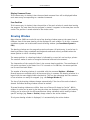
Main Window ..................................................................................... 67
Drawing Window ................................................................................ 68
Workflow Manager .............................................................................. 69
Overview Window ............................................................................... 70
Panel ............................................................................................... 71
Command Bar .................................................................................... 76
Ruler ................................................................................................ 79
Layout Window .................................................................................. 80
Status Window ................................................................................... 80
Block List ......................................................................................... 82
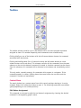
Toolbox ............................................................................................ 85
Malz++Kassner CAD6 User’s Manual
3
4
Contents
Plug-In Window ................................................................................. 88
Guide Window ................................................................................... 89
Popup Menu ...................................................................................... 90
Chapter 5 - Examples ....................................................................................... 91
Rules ............................................................................................... 91
The Rectangle.................................................................................... 92
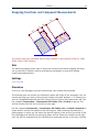
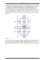
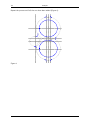
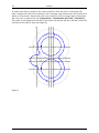
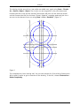
Snapping Functions and Compound Measurements ................................... 95
The Eccentric.................................................................................... 104
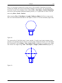
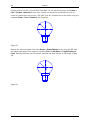
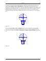
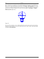
The Ballhead .................................................................................... 125
Using Surfaces in Construction ............................................................ 141
Gear Housing.................................................................................... 150
Tables and Parts Lists ........................................................................ 168
Diagrams ......................................................................................... 176
Trouser Leg ...................................................................................... 185
Libraries .......................................................................................... 195
Circuit Diagram ................................................................................. 199
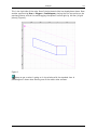
Dimetric and Isometric Drawing ........................................................... 210
Publisher:
Malz++Kassner GmbH
Leopoldstrasse 7a
38100 Braunschweig
Germany
Authors:
Timo Bierbaum
Olaf Kassner
Stefan Malz
Phone +49 531 400 137
Fax +49 531 400 138
Design:
Stefan Malz
www.malz-kassner.com
post@malz–kassner.com
Order Code:
20900.2
This manual, as well as the materials and data delivered with it, have been created with the utmost
care. However, we cannot guarantee that the manual is completely free of error. Accordingly, we
cannot take liability for any direct or indirect damages. No guarantee for errors and omissions.
Copyright Malz++Kassner GmbH. All rights reserved. Malz++Kassner is a registered trademark of
Malz++Kassner GmbH in Germany. No part of this manual may be reproduced or transmitted in any
form or by any means, electronic or mechanical, including photocopying, recording, or information
storage or retrieval system, with the express written permission.
All trademarks are property of their respective owners.
Printed in Germany
Malz++Kassner CAD6 User’s Manual
Information
5
Chapter 1 - Information
Conventions in This Reference
The following conventions are used throughout the reference:
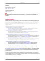
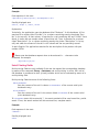
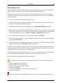
Very important: You should really read this!
Note
Tips & Tricks
Click
The word click by itself means click the left mouse button
once (sometimes also called left-click). Otherwise we say
right-click, or double-click.
SHIFT
This means the Shift key.
KEY1+KEY2
This means press KEY1 and KEY2 at the same time. For
example, ALT+TAB means hold down the ALT key while you
press the TAB key.
x+100+2/3
User input, e.g. text in edit controls.
Italic
Strengthening of single words or phrases.
MKCAD6.MKD
File name.
“Options”
When referring to elements in dialog boxes the element names
are displayed in quotation marks (e.g. “Options” button).
Shape > Modify Objects
This means the command “Modify Objects” in the “Shape”
menu of Malz++Kassner CAD6.
Malz++Kassner CAD6 User’s Manual
6
Information
System Requirements
General requirements:
• Windows 8 / 7 / Vista / XP / Server 2012 / Server 2008 / Server 2003
• Mouse or similar input device
• Processor with at least 500 MHz, 512 MB RAM
• XGA graphics with 24 bits color depth, 32 MB video RAM
• 20-70 MB hard disk space
Recommendations for Windows 8 / 7 / Vista / Server 2012 / Server 2008:
• Dual-Core Processor with at least 1 GHz, 1 GB RAM
• SXGA graphics with 32 bits color depth, 128 MB video RAM
Advice for Plotter Output
This section contains important information for Malz++Kassner CAD6 users who wish to
output their drawings on an HP-GL plotter. Most standard plotter drivers for Windows have
weaknesses. We strongly recommend that you use the Malz++Kassner HP-GL/2 export filter
instead. You can use this filter to export your drawing data to an HP-GL/2 file or you can
send your drawing data to the output device directly. The filter’s various output options
allow an exact configuration of the output data. You can download the filter from our Web
site (www.cad6.com) for testing.
Some capabilities of the application (filled surfaces, erasers, bitmaps, and clippings)
cannot be output to HP-GL plotters, or are limited on HP-GL/2 plotters!
Malz++Kassner CAD6 User’s Manual
Information
7
Using Digitizers
Working with Malz++Kassner CAD6 can be made a lot easier by using a digitizer (also known
as a “graphics tablet” or simply a “tablet”). A digitizer allows faster and more accurate
input than a conventional mouse and the digitizer’s large input area can also be used to
select commands.
A tablet with a size of 12 ×12 inches (305 × 305 mm) is perfect, however for certain
purposes smaller or larger tablets may be better suited. As input device you can basically
choose between the mouse-like cursor or a pen. The cursor normally has at least 4 or 5
buttons but some have significantly more. A pen has usually only 3 buttons and one of
these buttons is the pen’s pressure-sensitive tip.
General
All major digitizer manufacturers now offer drivers for Windows. A digitizer can be always
used as a replacement of the standard mouse (“Relative Mode”), but a digitizer only
becomes really productive when used in the so-called “Pen Mode” or “Absolute Mode”
(“WYPIWYG” Mode, “where you point is where you go”). If this mode is active a certain
tablet area is mapped on the screen, so that any position of the input device inside this
tablet area is mapped absolutely to the mouse pointer’s position on the screen. For
example, if you position your input device in the lower left corner of this tablet area then
also the mouse pointer is displayed in the lower left corner of the screen.
To be able to use a tablet in “Absolute Mode” it has to support the so-called WINTAB®
interface. All major digitizer manufacturers (for example Wacom®, Genius®, CalComp®, and
Summagraphics®) deliver along with the tablet appropriate drivers. If you have no driver for
your tablet or are looking for a newer version you can download the current driver from the
manufacturer’s Web site.
Setting up the Tablet
After the successful installation of the tablet driver you have to specify some settings in
the tablet driver’s control programs. Usually you can find the corresponding shortcut in the
Windows Control Panel. Although the relevant settings have different names in the various
manufacturer-specific control programs, you always have to specify the settings listed
below. You should not change the default values of the other settings.
Malz++Kassner CAD6 User’s Manual
8
Information
After you have specified all necessary settings in the control program you should exit and
restart Windows to activate them (maybe this is not always necessary but it also does no
harm). Then start CAD6 and choose the commands Construction > Digitizer > Button and
Tracing Options and Construction > Digitizer > Load Assignment to fit CAD6 to the
tablet. The CAD6 “Digitizer” menu is only available if the tablet driver is installed properly.
Position Mode (Control Program only)
Activate “Pen Mode” or “Absolute Mode” (“WYPIWYG” Mode, “where you point is where you
go”) respectively.
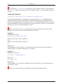
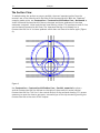
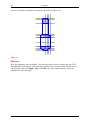
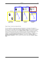
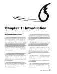
Tablet Area (Control Program and CAD6)
Set the option “Portion of Tablet” or “Enable Mapping” respectively and enter the measures
of the mapping area shown in the graphic corresponding to your tablet’s size. For that it is
important that you find out whether the measures of the mapping area in your control
program have to be entered relative to the lower left or upper left corner of the tablet. You
also have to enter the measures of the mapping area in the dialog of the command
Construction > Digitizer > Button and Tracing Options.
In the tablet driver’s control program you must enter all measures in inches (sometimes you
have to specify inches as current unit first) because the tablet sizes are also given in
inches. In the dialog of the command Construction > Digitizer > Button and Tracing
Options all measures are specified in 1/1000 inches relative to the lower left corner. So for
a 12 ×12 inches tablet you have to enter 5000 for the distance of the bottom margin.
Measures for 8 × 6 inches tablets:
3.2
1.8
Tablet Area
8×6 Inches
Mapping
Area
1.8
2.4
1.8
3.0
All Measures in Inches
Malz++Kassner CAD6 User’s Manual
Information
9
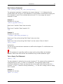
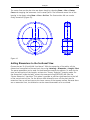
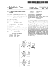
Measures for 12 × 12 inches (or larger) tablets:
3.8
3.2
5.0
4.6
Tablet Area
12×12 Inches
5.0
2.4
Mapping
Area
All Measures in Inches
Screen Area (Control Program only)
Activate the setting “Whole Screen” or “Complete” respectively. Sometimes you also have to
enter the resolution of you screen, e.g. 1280 × 1024 pixels.
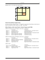
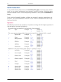
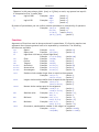
Define Buttons of the Input Device (Control Program and CAD6)
5-Button Crosshair Cursor (arranged in two rows, e.g. Wacom):
Button
Button
Button
Button
Button
0
1
2
3
4
Driver Settings
CAD6 Settings
Left Mouse Click
Middle Mouse Click
Right Mouse Click
None or Application Defined
None or Application Defined
Left Mouse Button + Command Level 1
Middle Mouse Button
Right Mouse Button + Command Level 2
Coordinate Tracing
Coordinate Tracing
4-Button Crosshair Cursor (arranged in one row, e.g. CalComp):
Button
Button
Button
Button
0
1
2
3
Driver Settings
CAD6 Settings
Driver Settings
CAD6 Settings
Left Mouse Click
Nothing or Application Defined
Middle Mouse Click
Right Mouse Click
Left Mouse Button + Command Level 1
Coordinate Tracing
Middle Mouse Button
Right Mouse Button + Command Level 2
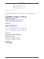
3-Button Pen:
Button 0 (tip) Left Mouse Click
Button 1
Double Left Mouse Click
Button 2
Right Mouse Click
Left Mouse Button + Command Level 1
Nothing
Right Mouse Button + Command Level 2
Malz++Kassner CAD6 User’s Manual
10
Information
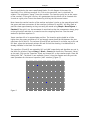
Load Assignment and Print Template (only CAD6)
Choose the Construction > Digitizer > Load Assignment command and load one of the
digitizer assignment files located in the Documents\Malz++Kassner\CAD6\Setting
directory. Which file to load depends on your digitizer’s size:
8 x 6 inches digitizer: DIGIT06.DIG
12 x 12 inches digitizer (or larger): DIGIT12.DIG
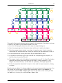
Finally, you should load and print the command template for your digitizer. This template
contains all predefined command fields available. Malz++Kassner CAD6 normally uses only a
small area in the center of the digitizer to map the screen. The remaining area is divided
into small square fields, each of which is linked to a command. If a field is clicked on, the
associated command is carried out as if it had been selected from the menu.
The digitizer templates are normal drawings that can be printed using the Print Drawing or
the Print Section command. Depending on the digitizer’s size, load the following drawing
file from the Documents\Malz++Kassner\CAD6\Setting directory:
8 x 6 inches digitizer: DIGIT06E.MKD
12 x 12 inches digitizer (or larger): DIGIT12E.MKD
Print out the drawing with the “Print to multiple sheets” option enabled, trim the sheets,
and fasten them together with sticky tape. Place the digitizer menu under the plastic cover
in the lower left corner of your digitizer.
The template also contains a graphic and a brief description on how to configure a
digitizer.
Malz++Kassner CAD6 User’s Manual
Information
11
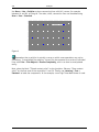
Deleting or Changing the Command Assignment
If you wish to change or delete the default command assignment, you can do so by using
the Define Digitizer Command Field or Delete Digitizer Command Field commands. These
commands are not shown in the menu but are selected by clicking on a command field on
the digitizer while at the same time keeping the SHIFT key or the SHIFT+CTRL keys pressed.
Tracing Templates
A common use for digitizers is tracing templates. If a cursor (sometimes with an attached
magnifier) is used, it is possible to trace with an precision of up to 1/1000 inches (0.0254
mm).
Malz++Kassner CAD6 can be used for tracing by reserving a button on the input device for
it. Using the Tracing Calibration and Set Tracing Origin commands the digitizer can be set
up accurately for this.
Afterwards points on the template can be transferred accurately and easily to a drawing
simply by clicking on them with the corresponding button of the digitizer’s input device.
Malz++Kassner CAD6 User’s Manual
12
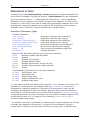
Introduction
Chapter 2 - Introduction
Data Display
Malz++Kassner CAD6 is a vector oriented technical drawing and illustration system. The
term “vector oriented” refers to a particular method of displaying data and objects which,
because of its high precision and independence from the screen and output resolution is
always used for CAD systems and illustration programs.
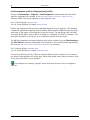
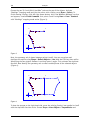
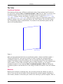
A line in Malz++Kassner CAD6 is described by the coordinates of its starting and ending
points. A 2D coordinate consists of X and Y values:
Y
(x1;y1)
Line
V1
V2
(x2;y2)
X
Figure 1: Mathematical display of a line
A vector is uniquely defined by its length and direction. These details can be used to
give each point within a layer a unique description.
Malz++Kassner CAD6 User’s Manual
Introduction
13
Y
(x1;y1)
Polygon
V1
V2
(x2;y2)
X
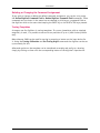
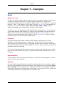
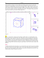
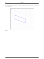
Figure 2: Mathematical display of a rectangle
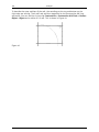
A rectangle is described by the coordinates of two diametrically opposite corner points
(figure 2). This shows one of the important characteristics of vector graphics: the number
and complexity of the objects in a drawing and not their size is responsible for the file size.
For output on your screen or printer, the object data is recalculated by the driver according
to the relevant resolution.
Malz++Kassner CAD6 User’s Manual
14
Introduction
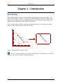
M
r
Data in memory
Data on screen/printer
Figure 3: Recalculation to the output resolution
This procedure may seem unnecessarily complicated, but it has the great advantage of only
carrying out the data conversion immediately before output. The points can be calculated
with much greater precision within the computer than they can be displayed or printed
with. This ensures that each graphic can be handled with the maximum precision
(depending on the resolution of the output device).
A further advantage of this method is that objects can be modified without problems. In a
vector graphic for example it is easy to scale a circle by changing the radius. In a bitmap
graphic on the other hand, the “old” circle has to be deleted and a new one has to be
drawn. Or you have to scale the area that contains the circle. But bitmap scaling always
yields poor results, e.g. jagged outlines etc.
Malz++Kassner CAD6 User’s Manual
Introduction
15
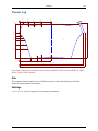
Coordinate Systems
The basis for screen display is a method of describing the position of each point in your
drawing. To do this, a coordinate system has to be defined. With the help of a coordinate
system, each point in a drawing can be given a unique description. The best known type of
coordinate system is the cartesian coordinate system. This consists of a coordinate origin
and two coordinate axes at right angles to one another which meet at the origin. Usually,
these axes are drawn horizontally and vertically. The horizontal axis is known as the X-axis
and the vertical axis as the Y-axis (figure 1).
Y
+20
+10
-20
-10
X
0
+10
+20
-10
-20
Figure 1: Cartesian coordinate system
Malz++Kassner CAD6 offers distorted forms of coordinate system to aid drawing in isometric
and dimetric perspectives. These coordinate systems differ mainly by having a
predetermined rotation angle and an altered height/width ratio. Further information on
these coordinate systems can be obtained from the reference and the example on dimetric
drawing.
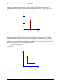
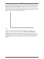
Determination of Coordinates
Further observations confine themselves to cartesian coordinate systems. Figure 1 shows
such a coordinate system. The X-axis is numbered from left to right, and the Y-axis from
bottom to top. In the standard Malz++Kassner CAD6 drawing window, the origin (that is,
the point at which X and Y are 0) at the bottom left of the page. The area available to you
is the area which is shaded on the graph. The origin can be moved to another point on the
page which will make it possible to draw in the other areas.
Malz++Kassner CAD6 User’s Manual
16
Introduction
Various ways can be used to identify a point uniquely. The simplest way is the use of
absolute coordinates. Absolute coordinates specify the precise X and Y values of a point
(Figure 2).
Y
+20
(10;15)
+10
X
0
+10
+20
Figure 2: Absolute coordinates
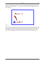
It is possible to identify a point by specifying its position relative to another point. These
are called relative coordinates. The first point is treated as if it were the origin and the
distance between the X and Y values of each point is given. In mathematics, this is often
abbreviated as dx and dy. When (x1;y1) are the absolute coordinates of the first point and
(x2;y2) are the absolute coordinates of the second point, the position of the second point
relative to the first can also be described as follows:
(x2;y2) = (x1+dx;y1+dy)
(Figure 3).
Y
+20
dy= -10
P1 (5;15)
+10
P2 (5+11;15-10)
dx=11
X
0
+10
+20
Figure 3: Relative coordinates
Malz++Kassner CAD6 User’s Manual
Introduction
17
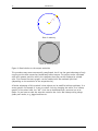
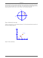
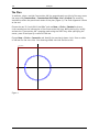
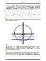
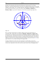
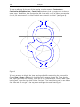
A third method is the use of polar coordinates. These coordinates are described by distance
from the origin and angle from the zero-angle. The mathematical zero-angle (that is, 0°) is
along the positive X-Axis, that is, at the “three o’ clock” position (Figure 4).
90°
0°
180°
270°
Figure 4: Mathematical zero-angle
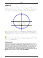
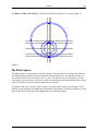
Angles are measured in an anti-clockwise direction. This form also describes the position of
each point uniquely (Figure 5).
Y
+20
(15;40°)
+10
15
l=
40°
0
+10
X
+20
Figure 5: Polar coordinates
Malz++Kassner CAD6 User’s Manual
18
Introduction
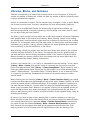
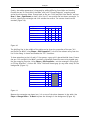
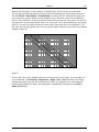
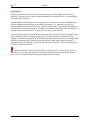
Layers, Pens, and Transmission
Each object, e.g. a circle, has its own property set consisting of line width, line pattern,
line color, fill color, and fill mode. These properties determine the appearance of the object
on the screen and later on the paper.
In addition, each object contains a reference to a layer and a pen, i.e. it lies in a certain
layer and uses a certain pen. When the program determines how to draw an object, this not
only depends on the object’s own properties, but also on the properties transmitted by the
assigned layer and the properties specified for the assigned pen.
Both the property set of the layer and the one of the pen do not permanently alter the
properties of the object itself, but do only overwrite them temporarily. As soon as the layer
or pen reference is changed, the object’s appearance will change accordingly - without
necessarily changing its properties.
Usually, layers do not transmit any properties, so they do not influence an object’s
appearance. In this case, the object’s appearance is only determined by the pen it uses, i.e.
by the pen’s properties (see View > Pens > Edit). Those pen properties may be different for
screen display and printer output.
If a layer property is transmitted (see View > Layers > Edit), it overwrites the
corresponding pen property. It is therefore decisive for the appearance of the object. Layer
properties may also be different for screen display and printer output.
Both types of property transmission (from a layer or a pen) can be refused by the object by
fixing one or several of its properties. These fixed properties cannot be overwritten by any
transmission and will always remain unchanged. Fixing a property will always effect both
screen display and printer output.
Layer “*Standard” and pen “*Standard” never transmit any properties. If an object is
assigned to the “*Standard” layer and the “*Standard” pen it isn’t influenced by changes
applied to layers or pens, i.e. the object is completely independent from layer and pen
settings. To draw such an object specify “*Standard” as current layer as well as current pen.
After drawing the object its properties are then initialized with those currently defined for
pen “*Standard”.
If you change the properties of pen “*Standard” this hasn’t any effect on already existing
objects but all objects you draw from then on will be initialized with these new properties.
To comfortably edit the properties of pen "*Standard" please select the command Window
> Display Command Bar and activate there the button groups Line Type, Line Color, Filling
Mode, and Filling Color.
To change the properties of a single object or multiple objects use the command Shape >
Edit Properties.
Malz++Kassner CAD6 User’s Manual
Introduction
Line Width
Line Color
Line Pattern
Full
0.35 mm
19
Fill Color
Black
Black
Fill Mode
Pen Properties
Outline
4
0.35 mm
01
3
Line Width
Pen
0,25 mm
05
001
001
1
Pen
01
2
Line Width
0.5 mm
Black
Black
Line Pattern
Line Color
Dotted
Red
Green
Transmitted!
Transmitted!
0.35 mm
01
Layer
Full
Full
Line Pattern
Fill Color
Red
Dashed
Fixed!
Line Width
0.5 mm
5
Outline
Fill Mode
Full
Line Pattern
Full
Red
Line Color
Red
Object Properties
Both
Fixed!
0.5 mm
Layer Properties
Green
Gray
Yellow
Fill Mode
Filled
Fill Color
Line Color
Outline
Gray
Fill Color
Gray
6
Fixed!
Both
7
Fill Mode
Both
Output / Screen
Properties
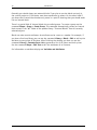
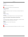
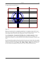
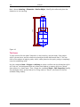
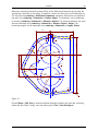
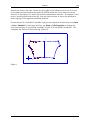
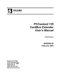
This graphic illustrates the process used to determine the properties of an object. Each step
is shown in the graphic by the relevant number in a circle:
1) First of all, the program determines which layer the object belongs to.
2) Next, the program gets the information about which pen is used by the object.
3) Then the program checks whether or not layer 1 transmits a pen. In such a case the
transmitted pen would become the current pen replacing the pen determined in step 2.
4) All pen properties are initially taken from the pen determined in step 2.
5) All properties transmitted by the layer override the corresponding pen properties, as
here the line color and the fill color.
6) The program checks each of the object’s own properties to see if it is fixed. Fixed object
properties are always passed on directly to the output / screen properties. In the
diagram line width, fill color, and fill mode are replaced by fixed object properties.
7) Finally the properties determined in step 1 to 6 are used for output to plotter / display
on screen.
When drawing an object, it is always assigned to the current layer and the current pen. You
can change the current layer by clicking the corresponding button in the Panel or by
selecting the command View > Layers > List. You can also select a new current pen from
the Panel or by choosing the command View > Pens > List.
Malz++Kassner CAD6 User’s Manual
20
Introduction
For some object types, e.g. texts or dimensions, you can optionally specify a default layer
(View > Layers > Defaults) and a default pen (View > Pens > Defaults) which then will be
used instead of the current layer or pen respectively when creating such an object.
If you want to assign an object to a different layer or pen later, you can do so by means of
the command Shape > Edit Properties.
Layers and pens are not only used to change the appearance of objects by property
transmission but also to structure a drawing logically. The Edit Layers / Edit Pens dialog
allows you to show or hide layers / pens, to enable or disable them for snapping or
modification, etc. If you create layers / pens with meaningful names and consequently
assign all newly created objects to these layers / pens, you will find that this feature will
greatly simplify your work.
In addition to the properties described above, each object can be assigned to a page (i.e.
to one of the pages defined in the drawing, see View > Pages > Edit). Once an object is
assigned to a page, it will only be output if this page is being output (or displayed on the
screen if this page is the active page).
The current pen and layer settings are part of the drawing and are saved with it. To
make the altered settings available when the program is restarted save them using the
command View > Template > Save as Default. In addition to all pens and layers the
current page format, pen and layer defaults, the coordinate systems, and the line patterns
will be stored as well.
Malz++Kassner CAD6 User’s Manual
Introduction
21
Coordinate Systems, Scales, Grids, etc.
Coordinate Systems
The coordinate systems determine the parameters which the program uses to process
drawing data. The coordinate system determines whether you wish to work in a cartesian,
isometric or dimetric system. By entering an angle of rotation the orientation of the
coordinate system can be displayed. In addition, you can specify measurement units for
lengths and angles as well as the type on number, floating point decimals and fractions.
The scale is saved with the coordinate system and the position and display grids can be set
here. You can set the coordinate system parameters via a dialog called with the command
View > Coordinate Systems > Edit.
Each drawing can have several coordinate systems defined within it. This can be useful if
you have several drawing windows and wish to use a different coordinate system with each
one, perform dimensioning in a different coordinate system to that you are drawing in, or
use objects with different scales in the same drawing.
To change the current coordinate system apply the corresponding button in the Ruler or
select the command View > Coordinate System > List.
Scales and Units
The most important components of a coordinate system are the scale and the units. The
scale determines the “real” size of an object, i.e. how large a drawn object is supposed to
be in the model world. Using a scale of 1:20 means that an object whose length is 10 cm
on the paper is supposed to have a length of 200 cm in reality.
Above all, scales are influencing dimensions, i.e. dimension statements within a drawing.
Dimension do always show the “real” size of an object based on the scale, and not its size
on the paper. This is why each dimension is directly linked to a coordinate system, out if
which is determines the scaling information. In addition, it uses the desired length and
angle units stored in the coordinate system for the dimension.
If dimensions are to be linked to a specific coordinate system, this can either be done in
advance by means of the Lettering > Dimension Parameters command, or afterwards by
means of the Shape > Edit Properties command.
Anyway, the scale and the units do not only influence dimensions placed in the drawing,
but all types of measurement, both during user entry (e.g. numerical input of a length) and
during screen output (e.g. the coordinate display in the Status Line).
If you do not like the default measurement units of a coordinate system during input,
you can choose different ones (e.g. cm instead of mm) by typing the abbreviation for that
unit after the figure. You can use this procedure in all dialogs. You can combine different
units in the same calculation (see Extra > Coordinate Input (F8)).
Malz++Kassner CAD6 User’s Manual
22
Introduction
Grids
Another important component of coordinate systems are grids, which are divided into
position grid and display grid.
The position grid is an invisible, regular series of points which the crosshair moves along.
The points are always the same distance in one direction from another. The horizontal and
vertical divisions can be different. The crosshair ‘snaps’ from point to point. This ensures
that you can only move the crosshair in multiples of the specified grid interval.
The display grid shows the grid as small dots on the screen. It can be set separately from
the position grid. You can choose a larger display grid than position grid. This speeds up
screen redraws considerably and makes for a better overview as not so many points obstruct
your view of the objects. If the zoom level is too small, that is if the display grid is too
small and the number of points to be shown too large, the display grid is first automatically
enlarged and then turned off. As soon as you revert to a level at which the grid can be
displayed, it is turned on again.
Both grids are valid for the currently active coordinate system and can be defined as part of
it.
The first point of each grid is at the origin. In order to be able to work with a common
starting point for the grid in different windows using different coordinate systems, the
origin should be moved so that all the grids can be used effectively. To do this, choose the
command View > Coordinate Systems > Set Origin.
Page Formats
Before starting a new drawing, it is often necessary to specify the page format for the
drawing. To do this, choose View > Pages > Edit. This calls a dialog where you can either
choose a standard page format or a custom page format. The page orientation is also
specified in this dialog.
Malz++Kassner CAD6 User’s Manual
Introduction
23
Snapping, Duplicate, and other Options
Snapping
In technical drawing it is not enough to determine the position of points approximately.
Most points have to be specified very precisely, which is not possible by hand.
Malz++Kassner CAD6 offers mathematical aids for positioning objects. During drawing it is
usual to orient yourself to preexisting construction points, such as edges, corners and
intersections. To make use of the points within these objects, there are several snapping
modes.
If the snap function is active during point entry, then the position of the point will be
calculated automatically if it lies within the snap radius. The snap radius is an area around
the center of the crosshair. It can be specified in a dialog called by choosing Extra > Snap
Modes > Snap Radius.
If several points lie within the snap radius determined by the current snap radius settings,
the crosshair will always be placed on the nearest one.
The snap function is permanently turned on or off with the F6 key. In addition, snap mode
can be briefly turned on with the SHIFT key. Using buttons in the Panel, single snapping
modes can be toggled.
Duplicate
Every alteration destroys the original object information. The original object information
can only be restored by using the UNDO function. To avoid these problems, Malz++Kassner
CAD6 has a duplicate function. It is permanently activated or deactivated by pressing the
F7 key. The function can be temporarily turned on or off during a command by pressing and
holding down the CTRL key. The current setting is shown in the panel and is reversed by
holding down the CTRL key.
The duplicate function is a good substitute for the “Copy” command, because it can be
combined with every command. The classic “Copy” command can be called by choosing
Shape > Move Object > Standard and keeping CTRL pressed while placing the objects (i.e.
entering the destination point). The duplicate function works similarly with most
commands that alter objects.
Malz++Kassner CAD6 User’s Manual
24
Introduction
Multiline
When creating new objects (e.g. drawing a line or circle), the “multiline function” can be
used. It determines whether several parallel or concentric objects are created at once
(depending on the multiline parameters) or not.
To activate or deactivate the multiline function please choose the command Duplicate /
Multiline (F7) or click the corresponding button in the Panel. To edit the parameters of
the multiline function please choose the command Multiline Parameters or right-click the
corresponding button in the Panel.
The multiline function can be temporarily turned on or off by pressing and holding
down the CTRL key.
General Options
The general program options and settings can be edited by selecting the command Edit >
Options > Windows or View > Drawing Settings > Screen respectively.
Malz++Kassner CAD6 User’s Manual
Introduction
25
Model Space and Pages
Before starting a new drawing, it is often necessary to specify the page format for the
drawing. To do this, choose View > Pages > Edit. This calls a dialog where you can either
choose a standard page format or a custom page format by double-clicking onto one of the
defined pages. The page orientation is also specified in this dialog.
CAD6 supports a Model Space and up to 100 pages in each drawing. Using those, drawings
can be structured in different ways depending on complexity and personal liking.
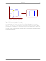
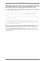
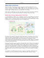
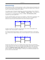
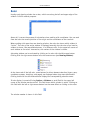
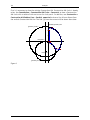
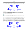
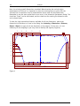
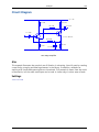
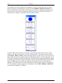
Model Space and Pages Independent of Each Other
If a drawing depicts a „Model“ (e.g. a component, a machine, a ground plan, etc.) of which
multiple sections shall later be printed at different places on the paper, maybe even using
different scales, it is advisable to place the model completely into the Model Space in order
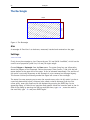
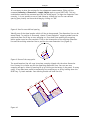
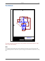
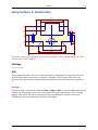
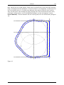
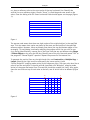
to map parts of it onto the pages later. Here is a schematic view:
All objects of the model are assigned to Model Space (green). Independent from the final
output, the model is usually designed in original size (1:1 scale). Once the drawing of the
model has been sufficiently finished, parts of the model will be mapped into one or
multiple pages (blue) using Mapping objects. In the respective pages, objects will be added
that are either scale-dependent (such as dimensionings) or part of the page's layout (such
as legends and drawing frames).
Mappings dynamically project a section of the Model Space within a page (like the image of
a supervision camera). Once the Model Space's content changes, the mappings will change,
too (at the latest during the next screen redraw). Mappings must always be assigned to
pages (not to the Model Space), the objects to be mapped must be part of the Model Space.
The objects visible within a mapping can be chosen for purposes such as snapping points or
drawing parallels, but they cannot be modified directly. This is only possible in the Model
Space.
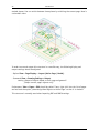
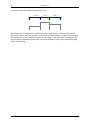
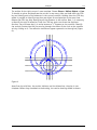
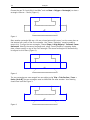
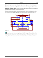
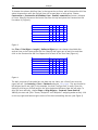
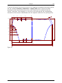
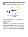
Since objects in the Model Space and objects in pages are completely independent from
each other, they can very well share the same coordinate range, resulting in logical,
Malz++Kassner CAD6 User’s Manual
26
Introduction
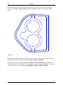
stacked planes. You can switch between these planes by switching the current page. Here is
a schematic view:
In order to use and output this structure in a sensible way, the following display and
output settings should be adjusted:
- Option View > Page Display > Layout (Active Page / Model).
- Command View > Drawing Settings > Output,
setting „Output of objects based on their page assignment“:
„Output current page's objects only“.
Furthermore, View > Pages > Edit should be called. There, right-click into the list of pages
and activate the option „Auto-Assign New Objects to Active Page“ so that it is checked.
This structure is normally used when importing DXF and DWG drawings.
Malz++Kassner CAD6 User’s Manual
Introduction
27
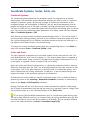
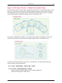
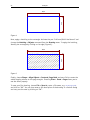
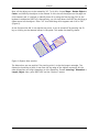
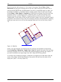
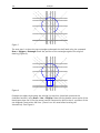
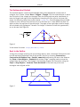
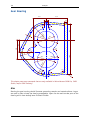
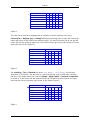
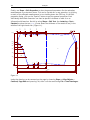
Pages as Model Space Dividers / Multiple Independent Pages
If the drawing consists of one huge, contiguous model (such as a land register plan, a hall
plan, etc.) that shall be printed onto multiple pages, the pages can be used to divide up
the Model Space by placing them above the Model Space like punching forms. The pages
can be rotated and/or scaled individually. Here is a schematic view:
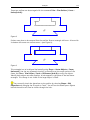
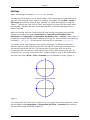
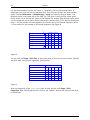
For multiple, independent models (e.g. a collection of separate components), the same
structure can be used, but with non-overlapping pages. Here is a schematic view:
In order to use and output this structure in a sensible way, the following display and
output settings should be adjusted:
- Option View > Page Display > Active Page + Model.
- Command View > Drawing Settings > Output,
setting „Output of objects based on their page assignment“:
„Output current page + model space“.
Malz++Kassner CAD6 User’s Manual
28
Introduction
Furthermore, View > Pages > Edit should be called. There, right-click into the list of pages
and clear the option „Auto-Assign New Objects to Active Page“ so that it is unchecked.
In this case, it may be useful to define a separate coordinate system for each page (View >
Coordinate Systems > Edit) in order to be able to set origin and scale independent for
each page. The respective coordinate system can be assigned to its page so that is will
automatically be activated when switching between pages.
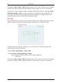
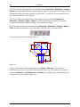
One Page
Simple drawings that easily fit onto one printer's page can be created completely in model
space as long as they lie inside the one page's extents. Here is a schematic view:
In order to use and output this structure in a sensible way, the following display and
output settings should be adjusted:
- Option View > Page Display > Classic (All).
- Command View > Drawing Settings > Output,
setting „Output of objects based on their page assignment“:
„Output all“.
Furthermore, View > Pages > Edit should be called. There, right-click into the list of pages
and clear the option „Auto-Assign New Objects to Active Page“ so that it is unchecked.
Malz++Kassner CAD6 User’s Manual
Introduction
29
Libraries, Blocks, and Instances
Libraries are organized in a hierarchical structure similar to the file system. A library can
contain any number of folders and a folder can hold any number of blocks. Folders are used
to group related blocks together.
A block is a collection of objects, like for example lines, rectangles, circles, or texts. Blocks
can be used to show screws, furniture, components for local area networks (LANs) etc.
There are a lot of predefined libraries for various areas of application available, e.g.
mechanical engineering, electrical engineering, interior design, and others. And of course
you can also create your own libraries.
The library / block concept not only allows you to efficiently organize and access frequently
used graphical data it also saves a lot of memory. When inserting a block in the drawing
you actually don’t insert the block’s object data but a reference to that block, the so-called
instance. I.e. the program inserts only the block name, the library name, and some display
parameters (e.g. position, scaling, rotation). Whereas the actual graphical data continues
to be stored only in the block definition in the library.
When drawing a block the program uses the block and library name stored in the instance
to locate the block definition in the library. The program then uses the graphical data in
the block definition and the display parameters stored in the instance to draw the block.
Because normally an instance requires much less storage than the actual block data, this
concept dramatically reduces memory consumption.
A library is an external file (*.MKL) which is independent from the drawing. To use a block
(Library > Block > Insert) of a specific library in a drawing you first have to load that
library into Malz++Kassner CAD6 (Library > Library Management). Blocks located in such a
library are called external blocks. Blocks can also be located in a so-called pseudo-library
named “*Internal Blocks”. The pseudo-library “*Internal Blocks” is not an external file but
it is located in the drawing. Consequently the blocks of the pseudo-library are called
internal blocks.
When creating your own libraries (Library > Block > Create (Insertion Point)) you should
consider the advantages and disadvantages of both block types. External libraries can easily
be used by several people in different drawings. If for example all people in company use
the same libraries located on a central server this helps to standardize drawings and also
makes it easy to update them. Because if you replace a library with an updated version (of
course the block names must remain unchanged) this update automatically will have an
effect on each drawing which contains instances of blocks of that updated library simply by
reloading the drawing.
Of course if you want to pass on your drawing files to another company or a client you
either also have to pass on the used library files or you have to convert the external blocks
into internal blocks using the command Library > Convert External Blocks. Alternatively
you could also use the command Library > Block > Resolve Block Instances to replace
each instance with the objects that make up the respective external block. But if the
drawing contains a lot of instances this will significantly increase the drawing’s size.
Malz++Kassner CAD6 User’s Manual
30
Introduction
Generally you should always use external blocks if you plan to use the blocks not only in
the current project or if the blocks must be accessed also by others. On the other hand if
you know that a certain block makes only sense in a specific drawing then you should make
him an internal block.
There is a special kind of internal blocks the so-called groups. To create a group use the
command Shape > Group > Create Group. This command automatically creates an internal
block stored in the “#G” folder of the pseudo-library “*Internal Blocks” from all currently
selected objects.
Blocks can also contain attributes. An attribute can be a text or a number. For example, if
you have a furniture library you can use the command Library > Block > Edit to add a price
attribute to every piece of furniture. After finishing the drawing you then can use the
command Library > Generate Parts List to generate a list of all pieces and their prices.
Use the command Shape > Edit Text to edit the attributes of an instance.
For information on attribute display see Variables and Attributes.
Malz++Kassner CAD6 User’s Manual
Introduction
31
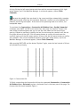
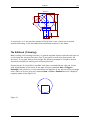
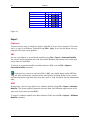
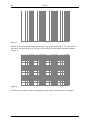
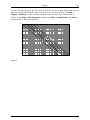
Dimensionings
Dimensionings are used in technical drawings in order to display measures of elements that
are required to manufacture the drafted object. Even though the measure itself is identical,
there are several ways to display such a measure.
Two standard types of dimension display forms are used most drawings. Once a dimension
command has been activated (e.g. Text > Dimension > Length, Points), the parameters of
this command can be edited either by calling the Extras > Edit Parameters (+ESC)
command or by pressing SHIFT+ESC.
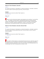
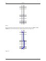
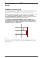
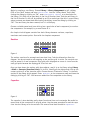
The first standard method, using arrows as end symbols, is mainly used in engineering. The
dimension line is terminated by a filled arrow on both sides, and it is aligned to the
extension lines that connect the dimension line with the measured object:
25
20
25
In order to create such a dimension, the dimension line end must be displayed in the
“Aligned” mode, the end symbol is a filled arrow.
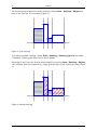
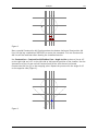
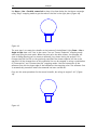
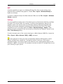
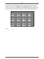
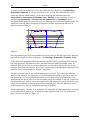
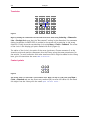
The second standard display method is used for architectural dimensions. It uses sloping
lines or filled circles instead of filled arrows, and the dimension line juts out the extension
lines:
25
20
25
Architectural dimensions often use a modified number display mode that automatically
converts values below one meter into centimeters and displays values below one centimeter
in superscript digits. You can active this number display mode either in the coordinate
system (see Coordinate Systems, Scales, Grids, etc.) that is assigned to the dimension
(button “Numbers”, entry “Length Display”), or directly in the dimension parameters that
you can reach as described above.
Malz++Kassner CAD6 User’s Manual
32
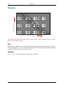
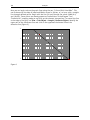
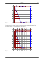
Introduction
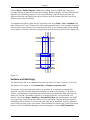
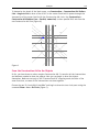
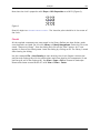
A typical architectural dimension looks like this:
1.29
25
95
75
1.38
75
Each dimension is assigned to a coordinate system from which it retrieves the required
information about the scale, length and angle units, and the desired number display mode.
The assignment of the coordinate systems is also done in the dimension’s parameters. By
using multiple coordinate systems you can realize different scales and/or dimension types
within one drawing.
Malz++Kassner CAD6 User’s Manual
Introduction
33
Text Input
In all text input fields within dialogs of Malz++Kassner CAD6, you have additional functions
that are extensions to the usual possibilities in such fields.
Term Evaluation
If the text input field contains a numeric term (see Term Evaluation), this term can be
evaluated by means of a single keystroke. In single-line input field, the term evaluation is
initiated by means of the “Arrow Up” key, in multi-line input fields by means of the “CTRL +
Arrow Up” key combination.
If, at the time of the initiation, a partial text is selected, the term evaluation will only
cover this selected text.
The result will be displayed by means of a small tooltip windows that disappears after a
short period.
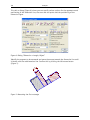
History of Previous Inputs
In all text input field, a list of the least recently entered texts can be called. In single-line
input field, this is done by means of the “Arrow Down” key, in multi-line input fields by
means of the “CTRL + Arrow Down” key combination.
A list of the least recently entered texts will appear, which also contains some additional
commands that will be described below.
List of Variables
The list of least recently entered texts (see above) also contains a list of all variables
defined by the user. By simple selecting them from the list, the variable can be inserted to
the text at the current cursor position. An additional command calls the dialog used to edit
these variables (see Edit > Edit Variables).
Search within the Field
Finally, some search commands are available that allow finding texts within the current
input field. They can either be selected from the list of least recently entered texts or
called by means of key shortcuts:
CTRL + F
Opens a dialog in which the text to be found can be entered. If at
the time of opening this dialog a part of the text in the field is
selected, this partial text will be copied into the dialog.
F3
Searches for the next occurrence of the text in forward direction,
starting with the current cursor position or text selection.
SHIFT + F3
Searches for the next occurrence of the text in backward direction,
starting with the current cursor position or text selection.
CTRL + F3
Searches in forward direction for the currently selected text, starting
behind the text selection.
Malz++Kassner CAD6 User’s Manual
34
SHIFT + CTRL + F3
Introduction
Searches in backward direction for the currently selected text,
starting before the text selection.
The last search text is globally saved, so that it remains available in the next dialogs.
Malz++Kassner CAD6 User’s Manual
Introduction
35
Text Formatting and Unicode
Inside any type of text Malz++Kassner CAD6 allows the use of text formatting and Unicode
characters. Both will be used analogically to HTML.
Text Formatting
The following code sequences are used analogically to HTML:
<b>
</b>
<i>
</i>
<s>
</s>
<u>
</u>
<sub>
</sub>
<sup>
</sup>
Bold font on.
Bold font off.
Italic font on.
Italic font off.
Strikeout on.
Strikeout off.
Underlining on.
Underlining off.
Smaller, lowered text on (index). The text will be scaled to 70.71% and will be
offset by 20% of the line height.
Smaller, lowered text off.
Smaller, lowered text on (power). The text will be scaled to 70.71% and will be
offset by 40% of the line height.
Smaller, lowered text off.
The following code sequences are an extension/modification of HTML:
<frac>XXX<sep>YYY</frac>
A fraction with numerator XXX and denominator
YYY. If you wish a separating line, simply
underline the numerator.
<font Type,Style,Weight,“Name“>
This sequence should always be inserted by
means of the button “Format> Font“ that is
available in all relevant dialog windows. This
avoids invalid values.
</font>
Restore original font.
<dx X>
Horizontal offset of X times type-size (“em quad“), with X being a floating
point number between -1000 and 1000.
</dx>
Resets the horizontal offset to 0 (will only work in vertical text direction
mode).
<dy X>
Vertical offset of X times type-size (“em quad“), with X being a floating
point number between -1000 and 1000.
</dy>
Resets the vertical offset to 0 (will not work in vertical text direction mode).
<tab X>
Jump to tabulator position at X times type-size (“em quad“), with X being a
floating point number between 0.001 and 1000.
<size X>
Relative scaling of the font by factor X, with X being a floating point number
between 0.001 and 1000.
</size>
Restore original scaling. This only reverses explicit scaling set using <size>.
<mode X>
Filling mode of the text, with X being an integer value stating the filling
mode: 0 = framed, 1 = filled, 2 = filled & framed, 3 = erased, 4 = erased &
framed.
Malz++Kassner CAD6 User’s Manual
36
</mode>
<fill R/G/B>
<fcmyk C/M/Y/K>
<fgray G>
<fhsb H/S/B>
<flab L/A/B>
</fill>
<line R/G/B>
<lcmyk C/M/Y/K>
<lgray G>
<lhsb H/S/B>
<llab L/A/B>
</line>
<afill X>
</afill>
<aline X>
</aline>
<width X>
</width>
<<
Introduction
Restore original filling mode.
Filling color of the text in RGB notation, with R, G, and B being
unsigned values between 0.0 and 1.0 inclusively, each defining the
red, green, or blue component of the color.
Filling color of the text in CMYK notation, with C, M, Y, and K being
unsigned values between 0.0 and 1.0 inclusively, each defining the
cyan, magenta, yellow, or black component of the color.
Filling color of the text in GRAY notation, with G being unsigned
values between 0.0 and 1.0 inclusively, defining the gray component
of the color (0=black, 1=white).
Filling color of the text in HSB notation, with H being an unsigned
value between 0 and 360 inclusively, S and B being unsigned values
between 0.0 and 1.0 inclusively, each defining the hue, saturation, or
brightness component of the color.
Filling color of the text in LAB notation, with L being an unsigned
value between 0 and 100 inclusively, A and B being signed values
between -127 and 127 inclusively, each defining the L*, a*, or b*
component of the color.
Restore original filling color.
Outline color of the text in RGB notation, with R, G, and B being
unsigned values between 0.0 and 1.0 inclusively, each defining the
red, green, or blue component of the color.
Outline color of the text in CMYK notation, with C, M, Y, and K being
unsigned values between 0.0 and 1.0 inclusively, each defining the
cyan, magenta, yellow, or black component of the color.
Outline color of the text in GRAY notation, with G being unsigned
values between 0.0 and 1.0 inclusively, defining the gray component
of the color (0=black, 1=white).
Outline color of the text in HSB notation, with H being an unsigned
value between 0 and 360 inclusively, S and B being unsigned values
between 0.0 and 1.0 inclusively, each defining the hue, saturation, or
brightness component of the color.
Outline color of the text in LAB notation, with L being an unsigned
value between 0 and 100 inclusively, A and B being signed values
between -127 and 127 inclusively, each defining the L*, a*, or b*
component of the color.
Restore original outline color.
Opacity (alpha value) of filling with X being an unsigned value
between 0.0 and 1.0 inclusively.
Restore original filling opacity. This only reverses explicit opacity set
using <afill>.
Opacity (alpha value) of outlines with X being an unsigned value
between 0.0 and 1.0 inclusively.
Restore original outline opacity. This only reverses explicit opacity
set using <aline>.
Line width of X millimeters, with X being a floating point number
between 0.001 and 1000.
Restore original line width.
Output the explicit character ‘<‘.
Malz++Kassner CAD6 User’s Manual
Introduction
Output the explicit character
Output the explicit character
Output the explicit character
Output the explicit character
\~
\{
\}
\\
37
‘~’.
‘{‘.
‘}’.
‘\’.
Examples (base font is “Arial“):
Code sequence in the text:
The <b>quick</b> brown fox <u>jumps</u> over the <i><b>lazy</b> dog</i>
Displayed text:
Code sequence in the text:
(a<sub>1</sub>+a<sub>2</sub>)<sup>2</sup>+
(b<sub>1</sub>+b<sub>2</sub>)<sup>2</sup>=
(c<sub>1</sub>+c<sub>2</sub>)<sup>2</sup>
Displayed text:
Code sequence in the text:
sin(<font
cos(<font
sin(<font
cos(<font
1,512,400,“Symbol“>a</font>)<sup>2</sup>+
1,512,400,“Symbol“>a</font>)<sup>2</sup>=
1,512,400,“Symbol“>b</font>)<sup>2</sup>+
1,512,400,“Symbol“>b</font>)<sup>2</sup>=1
Displayed text:
Code sequence in the text:
<frac><u> 1 </u> <sep>16 </frac>a+
<frac><u> 1 </u> <sep>16 </frac>b=
<frac><u> 1 </u> <sep>16 </frac>(a+b)
Displayed text:
Malz++Kassner CAD6 User’s Manual
38
Introduction
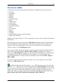
Unicode Characters
A Unicode character is represented by a code sequence analogically to HTML:
&#X;
Representation of the Unicode character X, with X being the Unicode character’s
number in decimal notation.
Example:
α
The small alpha (α) of the Greek alphabet, Unicode character 945.
You as a user will not see this representation of Unicode characters since all dialogs in the
program which handle text have an automatic translation of Unicode characters.
Malz++Kassner CAD6 User’s Manual
Introduction
39
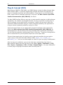
Variables and Attributes
Malz++Kassner CAD6 supports variables (valid for the total drawing) and attributes (variable
only valid within blocks). These variables are in fact text variables because variables can
contain numbers, texts, and statements (refer to Statements in Texts).
Basics
A variable has to be enclosed in tilde characters ~~ (Ansi 126) to be evaluated in texts or
statements respectively, e.g. ~Variable~. The text
Price: ~Price~ Euro
contains a variable named “Price“. If the variable “Price“ exists it is evaluated, i.e. the
string “~Price~“ is replaced by the value or the content of the variable “Price“. For example,
if the variable has the value 29.95 the following text is created:
Price: 29.95 Euro
If a text contains a variable that does not exist then this variable cannot be evaluated. In
such a case the variable is replaced by the text (***UNDEFINED***) . For the example
above the resulting text would be:
Price: (***UNDEFINED***) Euro
To output the explicit tilde character please use \~.
Customizable Drawing Variables
Drawings can contain any variables that can be used throughout the drawing. These
variables can be defined by means of the Edit > Edit Variables command.
Example:
Code sequence in the text:
File Version: ~Version~
Possibly displayed text:
File Version: 6.2.0
Please note that variables have to be enclosed in ~ characters to be evaluated, for
example:
~Version~
Fixed Drawing Variables
Fixed drawing variables always exist and are automatically initialized by CAD6. They cannot
be changed by the user.
The following fixed drawing variables are available:
Malz++Kassner CAD6 User’s Manual
40
Introduction
%A0 or
%A1 or
%A2 or
%a0
%a1
%a2
Name of the author who created the drawing
Name of the author who last saved the drawing
Name of the author who is just working with the drawing
%N0
%N1
%N2
%N3
or
or
or
or
%n0
%n1
%n2
%n3
File name of the serial printing database (including path)
Title of the serial printing database
Number of data records for serial printing
Current data record for serial printing
%D0
%D1
%D2
%D3
%D4
%D5
%D6
%D7
%D8
or
or
or
or
or
or
or
or
or
%d0
%d1
%d2
%d3
%d4
%d5
%d6
%d7
%d8
Creation date of the drawing
Last saved date of the drawing
Current date
Current year (1998, 2006, ..)
Current month (01..12)
Current day of month (01..31)
Current hour (00..23)
Current minute (00..59)
Current second (00..59)
%P0
%P1
%P2
%P3
%P4
%P5
%P6
%P7
%P8
or
or
or
or
or
or
or
or
or
%p0
%p1
%p2
%p3
%p4
%p5
%p6
%p7
%p8
Number of pages
Total number of sheets in multiple sheets printing mode
Current sheet number in multiple sheets printing mode
Page number (this object lies in)
Width of the page (this object lies in) in [mm]
Height of the page (this object lies in) in [mm]
Width of the page (this object lies in) in [inch]
Height of the page (this object lies in) in [inch]
Comment of the page (this object lies in)
%S0
%S1
%S2
%S3
or
or
or
or
%s0
%s1
%s2
%s3
Scale of the active coordinate system
Output scaling factor (as entered in printing dialog)
Output scaling factor (as defined by page scaling)
Output rotation angle (as defined by page rotation) in [deg]
%V0 or
%V1 or
%v0
%v1
First dimension value (in any type of dimension)
Second dimension value (only in a coordinate dimension)
%X0
%X1
%X2
%X3
%X4
%X5
or
or
or
or
or
or
%x0
%x1
%x2
%x3
%x4
%x5
File size in KB (in memory)
Number of objects in the drawing
Number of internal blocks in the drawing
Number of used external blocks
Number of used bitmaps
Number of used external references
%Z0
%Z1
%Z2
%Z3
%Z4
%Z5
or
or
or
or
or
or
%z0
%z1
%z2
%z3
%z4
%z5
File name of the drawing (including path)
Title of the drawing
Topic of the drawing
Comment on the drawing
File name of the drawing (without path)
File name of the drawing (without path and extension)
Malz++Kassner CAD6 User’s Manual
Introduction
41
Example:
Code sequence in the text:
Page ~%p3~ of ~%p0~
Possibly displayed text:
Page 1 of 16
Please note that variables have to be enclosed in ~ characters to be evaluated, for
example:
~%a0~
Database Requests
Database requests are only available if the user has opened the corresponding database by
means of the command Library > Databases and serial printing is active. Each cell of the
database is considered to be a (virtual) variable which can be evaluated by means of a
database request.
A database request has one of the following forms:
%[DatabaseName]ColumnNumber,RowNumber
Gets the content of the cell in column ColumnNumber (starting with 1) and row
RowNumber (starting with 1) of the database titled DatabaseName.
%[DatabaseName]“ColumnName“,RowNumber
Gets the content of the cell in the column titled ColumnName and row RowNumber
(starting with 1) of the database titled DatabaseName.
%[DatabaseName]ColumnNumber,“FindText“@FindColumnNumber
Gets the content of the cell in column ColumnNumber (starting with 1) and the row
that contains the string FindText in column FindColumnNumber (starting with 1).
%[DatabaseName]ColumnNumber,“FindText“@“FindColumnName“
Gets the content of the cell in column ColumnNumber (starting with 1) and the row
that contains the string FindText in the column titled FindColumnName.
%[DatabaseName]“ColumnName“,“FindText“@FindColumnNumber
Gets the content of the cell in the column titled ColumnName and the row that
contains the string FindText in column FindColumnNumber (starting with 1).
%[DatabaseName]“ColumnName“,“FindText“@“FindColumnName“
Gets the content of the cell in the column titled ColumnName and the row that
contains the string FindText in the column titled FindColumnName.
If ColumnName, FindText, or FindColumnName starts with as asterisk ‘*’, the search method
will be case-insensitive, partial match. If not, the search method will be case-sensitive,
complete match.
In order to access the default internal database of the current database, use an asterisk ‘*’
only as database name. To access another internal database, use an asterisk followed by the
internal database's name, e.g. “*Partslist1”.
Malz++Kassner CAD6 User’s Manual
42
Introduction
Example:
Code sequence in the text:
~%[Products]“Description“,“53790“@“Part No“~
Possibly displayed text:
Switch, Shape C, small, black
Explanation:
Technically, the application uses the database titled “Products“. In this database, it first
searches for a column titled “Part No“ (i.e. a column containing exactly the phrase “Part
No“ in its top cell). In that column, it searches for a cell containing the text “53790“. Once
found, it stores the row number where it found that cell. Then, it searches for a column
titled “Description“ (i.e. a column containing exactly the phrase “Description“ in its top
cell) and takes the content of the cell in this column and the row previously stored.
In plain English: The application searches for the description of the product with part
number 53790.
Please note that database requests have to be enclosed in ~ characters to be
evaluated, for example:
~%[Products]12,15~
Serial Printing Fields
Serial printing fields are only available if the user has opened the corresponding database
by means of the command Library > Databases and serial printing is active. Each cell of
the database is considered to be a (virtual) variable which can be evaluated by means of a
serial printing field.
Serial printing fields have one of the following forms:
%#ColumnNumber
Gets the content of the cell in column ColumnNumber of the current serial print
database’s entry.
%“ColumnName“
Gets the content of the cell in the column titled ColumnName of the current serial
print database’s entry.
If ColumnName starts with as asterisk ‘*’, the search method will be case-insensitive, partial
match. If not, the search method will be case-sensitive, complete match.
Example:
Code sequence in the text:
~%“Name“~
Possibly displayed text:
Smith
Malz++Kassner CAD6 User’s Manual
Introduction
43
Explanation:
The application uses the column titled “Name“ (i.e. a column containing exactly the phrase
“Name“ in its top cell) of the database selected for serial printing, and returns the column
content of the row currently selected by the user (or the serial printing process).
Please note that serial printing fields have to be enclosed in ~ characters to be
evaluated, for example:
~%“Name“~
Attributes
If you want to display attributes of a block, you have to know this before you create that
block. Let’s assume you want to create a block containing the symbolic representation of an
electric resistor. This symbol should contain a text that displays the resistor’s resistance.
The resistance will be stored in a local attribute of the block to be created, as this local
attribute may have different values for each instance of the block. In our example, this
attribute shall be called “Resistance“.
Now, let’s create the block. First, draw the resistor itself. A rectangle and maybe two line
for the connections will do. Then, create a standard text (Lettering > Text > Standard)
containing just the following short text:
~Resistance~
Place this text inside the resistor’s rectangle. Please note that this text will also be rotated
and scaled if you rotate or move the block itself later on! So make sure the text’s position
will still make sense then.
After you have created all components of the resistor symbol, create a block using Library
> Block > Create (Insertion Point). In the dialog appearing, set the “Edit Attributes“
check box. After entering a name for the block and pressing “OK“, another dialog appears.
Here, add a local attribute named “Resistance“ to this block. Initialize it with any useful
value, e.g. “100 ohm“.
After you have created this block, you are ready to use the resistor symbol. Create multiple
instances of this block using the Library > Block > Insert command. Be sure that the
“Copy Attributes“ check box is set in the block selection dialog!
You will see that all resistor symbol placed display the same text “100 ohm“. Now, choose
the Shape > Edit Text command and identify one of these resistor symbols. In the
appearing dialog, change the value of the “Resistance“ attribute to “10 kohm“. After
pressing “OK“, the identified resistor symbol will display “10 kohm“ instead of “100 ohm“.
Malz++Kassner CAD6 User’s Manual
44
Introduction
If you want to edit the attribute’s value for each block you place, you can simply set the
“Edit Attributes“ check box in the block selection dialog of the Library > Block > Insert
command. This will display the “Edit Attributes“ dialog each time you place a symbol.
Please note that attributes have to be enclosed in ~ characters to be evaluated, for
example:
~Resistance~
Implicit Attributes
Implicit attributes are a special kind of local attributes. They are owned by any block, even
though they are not visible to the user, and are usually used for parts lists. They are used
to store internal information such as the block name, library name, position, etc.
The following implicit attributes are available:
*00
*01
*04
*05
*06
*07
*08
*09
The name of the block itself.
The name of the library the block reside in.
X-coordinate of the block’s insertion point in internal millimeters, i.e. relative to
the page’s center and non-scale-dependent.
Y-coordinate of the block’s insertion point in internal millimeters, i.e. relative to
the page’s center and non-scale-dependent.
Rotation of the block in degrees.
Horizontal scaling of the block relative to 1.
Vertical scaling of the block relative to 1.
Horizontal distortion (shearing) of the block in degrees.
Please note that attributes have to be enclosed in ~ characters to be evaluated, for
example:
~*05~
Object Properties
Object properties are variables allowing to access properties of specific objects by means of
their unique ID.
The following object properties are available:
*p0(UniqueID)
*p1(UniqueID)
*p2(UniqueID)
*p3(UniqueID)
The surface area of the object with the given unique ID in square
millimeters (if available, otherwise 0).
The perimeter / length of the object with the given unique ID in square
millimeters (if available, otherwise 0).
The dimension number of the object with the given unique ID in square
millimeters (if available, otherwise empty string).
The text in the object with the given unique ID in square millimeters (if
available, otherwise empty string).
Malz++Kassner CAD6 User’s Manual
Introduction
*p4(UniqueID)
*p5(UniqueID)
45
The X-coordinate of the object with the given unique ID in internal
millimeters, i.e. relative to the page's center and non-scale-dependent
(if available, otherwise 0).
The Y-coordinate of the object with the given unique ID in internal
millimeters, i.e. relative to the page's center and non-scale-dependent
(if available, otherwise 0).
Please note that object properties have to be enclosed in ~ characters to be evaluated,
for example:
~*p0(0E96B221D35D6F4796CC05A5000F6045)~
Miscellaneous
Further variables are used by the program for internal purposes:
#AutoPosNum
An automatically generated position number.
Please note that variables have to be enclosed in ~ characters to be evaluated, for
example:
~#AutoPosNum~
Malz++Kassner CAD6 User’s Manual
46
Introduction
Term Evaluation
In any numerical entry field, such as the Coordinate Entry (F8) or the entry of a rotation
angle, you can state a mathematical term instead of an explicit number. In addition terms
are also evaluated in texts if the corresponding statement is used (refer to Statements in
Texts).
Terms consist of operands (numbers, variables, or constants), operators, parentheses, and
functions. The usual mathematical notation is used. A term is evaluated from left to right
(left-associativity).
Operators
The following list shows the precedence of operators starting with the highest (operators in
the same group have equal precedence):
An operand may by preceded with a single sign (unary operator):
Sign
Example: +8
(result: 8),
-2
(result: -2)
+ or -
This unary operator always yields 0 (operand not equal 0) or 1 (operand is 0) as result
Logical NOT
Example: 0
(result: 1),
12
(result: 0)
^^
Power
Example: 2^^8
(result: 256)
*
Multiplication
Example: 3*4
(result: 12),
2^^8*2
(result: 512)
/
Division
Example: 8/2
(result: 4),
8/2*4
(result: 16)
+
Addition
Example: 8+2
(result: 10),
8+2*4
(result: 16)
Subtraction
Example: 10-2
(result: 8)
!
Operators in this group always yield 1 (true) or 0 (false) as result:
Less than
Examples: 1<2
(result: 1),
8<5
(result: 0)
<=
Less or equal
Examples: 2<=2
(result: 1),
8<=5
(result: 0)
>
Greater than
Examples: 1>0
(result: 1),
5>8
(result: 0)
>=
Greater or equal
Examples: 1>=1
(result: 1),
5>=8
(result: 0)
==
Equal
Examples: 1==1
(result: 1),
5==8
(result: 0)
!=
Unequal
Examples: 1!=0
(result: 1),
5!=5
(result: 0)
&
Bitwise AND
Example: 24&15
(result: 8)
|
Bitwise OR
Example: 16|8
(result: 24)
^
Bitwise XOR
Example: 24^31
(result: 7)
<
Malz++Kassner CAD6 User’s Manual
Introduction
47
Operators in this group always yield 1 (true) or 0 (false) as result, any operand not equal 0
is interpreted as true, 0 means false:
&&
Logical AND
Examples: 1&&!0
(result: 1),
0&&1
(result: 0)
||
Logical OR
Examples: 5||0
(result: 1),
0||0
(result: 0)
By means of parentheses you can enforce another precedence or associativity of operators:
()
Examples: (8+2)*4
(result: 40),
8/(2*4)
(result: 1)
2^^(8*2)
(result: 65536),
(0!=1)||(8<5)
(result: 1)
Functions
Arguments of functions must be always enclosed in parentheses. If a function requires two
arguments then these arguments have to be separated by a semicolon. The following
functions are available:
sqr
sqrt
ln
sin
cos
tan
arcsin
arccos
arctan
ceil
floor
round
abs
min
max
rand
Square
Example: sqr(4)
(result: 16)
Square root
Example: sqrt(256)
(result: 16)
Logarithm with base e (natural logarithm)
(result: 100)
Example: e^^(2*ln(10))
Sinus
Example: sin(90)
(result: 1)
Cosinus
Example: cos(0)
(result: 1)
Tangens
Example: tan(45)
(result: 1)
Arcussinus
Example: arcsin(1)
(result: 90)
Arcuscosinus
Example: arccos(1)
(result: 0)
Arcustangens
Example: arctan(1)
(result: 45)
Smallest whole number larger than or equal to the argument
Examples: ceil(1.9)
(result: 2),
ceil(2.4-0.5)
(result: 2)
Largest whole number smaller than or equal to the argument
(result: 1),
Examples: floor(1.9)
floor(1.6+0.5)
(result: 2)
Nearest whole number equal to the argument
(result: 1),
Examples: round(1.1)
round(2.4-0.5)
(result: 2)
Absolute value
Examples: abs(-1.1)
(result: 1.1),
abs(-2)
(result: 2)
Minimum
Examples: min(-1;2)
(result: -1),
min(1.6;2.4)
(result: 1.6)
Maximum
Examples: max(-1;2)
(result: 2),
max(1.6;2.4)
(result: 2.4)
Generates a pseudorandom number in the range 0 to argument.
Examples: rand(1)
(result: 0.6586),
rand(100)
(result: 17.3681)
Malz++Kassner CAD6 User’s Manual
48
Introduction
Variables
In case you have defined variables within the active drawing by means of the Edit > Edit
Variables command you can use those as operands as well. For that you have to enclose
the variable name in ~characters (same as with variables in text, see Variables and
Attributes):
Example:
(~var1~+~var2~)/2 (result: mean value of var1 and var2)
Constants
According to the type of input being carried out, certain constants are available which can
be used in the terms. They allow, for example, relative values to be entered during
coordinate entry. The following constants are available:
x and y
l
r
a and w
b
Current X- and Y-coordinates of the reference point
Current length of the reference object or previously entered line section
Current radius of the reference object
Current angle of the reference object or previously entered line section
Current arc length of the reference object
_fl
_fr
_ft
_fb
“Frame Left“
“Frame Right“
“Frame Top“
“Frame Bottom“
Rectangular coordinates of the frame which surrounds all currently selected
objects.
_pl
_pr
_pt
_pb
“Page Left“
“Page Right“
“Page Top“
“Page Bottom“
Corner coordinates of the current page.
e
pi
Base number for natural logarithms (2.7182...)
pi (π) (3.1415...)
Malz++Kassner CAD6 User’s Manual
Introduction
49
Units
All values entered without a specific unit relate to the current length or angle unit of the
active window’s coordinate system.
To specify a unit for a value, the appropriate abbreviation should be used. These are the
possible units and their abbreviations.
µm
mm
cm
dm
m
km
mil
in
ft
yd
ml
dp
pt
bp
cic
Micrometer
Millimeter
Centimeter
Decimeter
Meter
Kilometer
Mil
Inch
Foot
Yard
Mile
Decipoint
Point
Didot
Cicero
1/1000 mm
1 mm
10 mm
100 mm
1000 mm
1000000 mm
1/1000 in
1 in = 25.4 mm
12 in
3 ft
1760 yd
1/720 in
1/72 in
1/2660 m
12/2660 m
Possible angle units and abbreviations
deg or °
min or ‘
min or “
gra
rad
rel
Degree
Minute
Second
Gon
Radian
Relative
360 per rotation
1/60 degree
1/3600 degree
400 per rotation
2pi per rotation
1 per rotation
Units can be mixed within a term. These are examples using mm as the current length unit
and deg as the current angle unit.
100+1in
(100+1)in
2yd+1ft+9,5in
sin(pi rad)
45°60’3600“
equals
equals
equals
equals
equals
100 mm + 1 in = 125.4 mm
101 in = 2565.4 mm
93.5 in = 2374.9 mm
sin(180°) = 0.0
47°
Malz++Kassner CAD6 User’s Manual
50
Introduction
Statements in Texts
If enabled by the user (Drawing Settings > Screen) statements in texts are evaluated. This
can be used, for example, to display the result of a Term Evaluation. For that a statement
has to be enclosed in braces { }. Additionally the opening brace { can be immediately
followed by a control character which defines the type of the statement. The result of the
evaluation is a text which is then used to replace the corresponding statement text. If the
resulting text is empty the statement text is deleted. The assignment and the comment
statement have no result text, here the statement text is always deleted.
Overview of Statement Types
Functional Statements:
{=Var {Term}}
{=Var {$Text}}
{?Condition {Term1}{Term2}}
{?Condition {$Text1}{$Text2}}
{!Var {Term1}{Term2}}
{!Var {$Text1}{$Text2}}
{$Text} / {$}
{*Comment}
Assignment statement (term evaluation)
Assignment statement (text copying)
Conditional statement (term evaluation)
Conditional statement (text copying)
Non-existence-statement (term evaluation)
Non-existence-statement(text copying)
Text or empty text statement respectively
Comment statement
Numerical Term Statements (yield the result of the term evaluation):
{Term}
Maximum number of decimal places
{%Term}
Rounded
{.Term}
Rounded, decimal point
{,Term}
Rounded, decimal comma
{+Term}
Rounded, decimal point, always with sign
{&Term}
Rounded, decimal comma, always with sign
{#Term}
Integer
C-Type Statements (yield the result of the term evaluation):
{f Term}
Floating-point value
{g Term}
Exponential value
{d Term}
Signed integer value
{x Term}
Unsigned hexadecimal value
{b Term}
Unsigned binary value
Var here means variable name without tilde characters. $Text denotes a text which is not
evaluated as a numerical term, but initially copied only. Condition is a text which is
interpreted as a numerical expression. If the result of this expression is zero then the
condition is considered to be false (not fulfilled). Any other result means the condition is
true (fulfilled). If the first condition is true then the first statement ({Term1} or {Text1})
is executed, otherwise the second. Similarly for the non-existence-statement applies: If the
variable does not exist or if it is empty the first statement ({Term1} or {Text1}) is
executed, otherwise the second.
Term denotes a text which is evaluated as a numerical term (control characters can be used
to change the presentation of the result). The result of a term evaluation is always a
number which is written to the result text according to its type (which is defined by the
Malz++Kassner CAD6 User’s Manual
Introduction
51
control character). An empty {} term always yields 0.0. If a syntax error occurs then the
result text contains (***SYNTAX ERROR***) afterwards. For rounding the number of
decimal places set by the user is used. If the decimal separator is not specified by the
statement type the active decimal separator is applied.
If the result text is part of a text object which is displayed on screen, printed or exported,
then the total text is evaluated as long as there are no more statements. This also applies
to the control texts of the CAM postprocessor. That means, the resulting total text does not
contains any braces { } afterwards, except those that have been inserted as explicit
characters (\{ \}).
The spaces in the statement texts are not required, they have been added only for better
readability.
Samples
Assignment Statement
{=Var {Term}} or {=Var {$Text}}
The assignment statement is marked by the control character ‘=‘, it is followed by the
variable name and a term or text statement. If the specified variable exists, the result of
the term evaluation is assigned to that variable or the text is copied to the variable. If the
variable does not exist a syntax error is output.
Example 1:
Statement in the text:
{=Counter {# ~Counter~ + 15}}
Result text:
None
Explanation:
The variable “Counter“ is incremented by 15. The assignment statement does not create an
output.
Example 2:
Statement in the text:
{=String {$This is a text}}
Result text:
None
Explanation:
The text “This is a text“ is copied to the variable “String“. The assignment statement does
not create an output.
Malz++Kassner CAD6 User’s Manual
52
Introduction
The statement {=Counter{0}} assigns zero to the variable “Counter“. The statement
{=String{$}} assigns an empty text to the variable “String“, i.e. the variable’s content is
cleared.
Conditional Statement
{?Condition {Term1}{Term2}} or {?Condition {Text1}{Text2}}
The assignment statement is marked by the control character ‘?’, it is followed by the
numerical condition (which may include a complete term along with variables) and two
term or text statements. If the condition is true, i.e. the numerical expression is non-zero,
the first statement is used. On the other hand, if the condition is false, i.e. the numerical
expression is zero, the second statement is used.
Please note that in order to compensate the internal calculation inaccuracy values
between -1e-10 and 1e-10 are also considered to be “false“.
Example 1:
Statement in the text:
{? ~Value~!=0 {100/~Value~}{0}}
Result text (variable “Value“ equals 5):
20.0
Result text (variable “Value“ equals 0):
0.0
Explanation:
If the condition is true (“Value“ is non-zero) the result of the division 100 divided by
variable “Value“ is output. Otherwise “0.0“ is output.
Example 2:
Statement in the text:
{? ~Value~> 5 {$Big}{$Small}}
Result text:
Big oder Small
Explanation:
If the condition is true (“Value“ is greater than 5) the text “Big“ is used. Otherwise the
text “Small“ is used.
Please note that the two text statements may include statements again.
Malz++Kassner CAD6 User’s Manual
Introduction
53
Non-Existence Statement
{!Var {Term1}{Term2}} or {!Var {Text1}{Text2}}
The assignment statement is marked by the control character ‘!’, it is followed by the
variable name and two term or text statements. If the variable is not defined or empty the
first statement is used. If the variable does exist and if it is not empty the second
statement is used.
Example 1:
Statement in the text:
{!Value {0}{100*~Value~}}
Result text if variable “Value“ does not exist:
0
Result text if variable “Value“ equals 0.75:
75,0
Example 2:
Statement in the text:
{! %“Name“ {$No Name}{$~%“Name“~}}
Result text if the serial printing field “Name“ does not exisat:
No Name
Result text if the serial printing field “Name“ has the content “John Q. Public“:
John Q. Public
Explanation:
You can use the non-existence-statement to define what happens if a variable does not
exist or is empty.
This statement is especially useful to output serial printing fields and database
requests. Please note that the two text statements may include statements again.
Text or Empty Text Statement
{$Text} / {$}
The text statement is marked by the control character ‘$’. The content of the statement is
copied directly as a text, i.e. there is no evaluation. This especially useful inside
conditional statements. Please not that the text to be copied starts directly after the $
character . Is the $ character directly followed by }, i.e. the text is empty, then an empty
text is copied.
Example 1:
Statement in the text:
{$This is a text}
Malz++Kassner CAD6 User’s Manual
54
Introduction
Result text:
This is a text
Explanation:
The text is copied without any modification.
Please note that text statements may include statements again.
Comment Statement
{*Comment}
The comment statement is not output. This can be used to store hidden information in a
drawing.
Example:
Statement in the text:
{* This is a comment}
Explanation:
This statement is neither displayed on the screen, nor will it be printed or exported.
Numerical Term Statement, Maximum Number of Decimal Places
{Term}
The content of the braces is interpreted as a numerical expression, calculated and output
with the maximum number of decimal places (currently 15).
Example:
Statement in the text (the variable “Value“ equals 1):
{~Value~/3}
Result text:
0.333333333333333
Please note that the decimal separator used depends on user settings, it can be either
‘.’ or ‘,’.
Malz++Kassner CAD6 User’s Manual
Introduction
55
Numerical Term Statement, Rounded
{%Term}
The content of the braces is interpreted as a numerical expression, calculated, rounded to
the active number of decimal places (here five), and then output.
Example:
Statement in the text (the variable “Value“ equals 1):
{% ~Value~/3}
Result text:
0.33333
Please note that the decimal separator used depends on user settings, it can be either
‘.’ or ‘,’. The number of decimal places is mostly determined by the active coordinate
system. If the statement is part of a dimension text then the number of decimal places
specified in the object’s dimension parameters is used. For control texts of the CAM
postprocessor the corresponding value from the postprocessor settings is used.
Numerical Term Statement, Rounded, Decimal Point
{.Term}
The content of the braces is interpreted as a numerical expression, calculated, rounded to
the active number of decimal places (here five), and then output. A point is used as
decimal separator.
Example:
Statement in the text (the variable “Value“ equals 1):
{. ~Value~/3}
Result text:
0.33333
The number of decimal places is mostly determined by the active coordinate system. If
the statement is part of a dimension text then the number of decimal places specified in
the object’s dimension parameters is used. For control texts of the CAM postprocessor the
corresponding value from the postprocessor settings is used.
Malz++Kassner CAD6 User’s Manual
56
Introduction
Numerical Term Statement, Rounded, Decimal Comma
{,Term}
The content of the braces is interpreted as a numerical expression, calculated, rounded to
the active number of decimal places (here five), and then output. A comma is used as
decimal separator.
Example:
Statement in the text (the variable “Value“ equals 1):
{, ~Value~/3}
Result text:
0,33333
The number of decimal places is mostly determined by the active coordinate system. If
the statement is part of a dimension text then the number of decimal places specified in
the object’s dimension parameters is used. For control texts of the CAM postprocessor the
corresponding value from the postprocessor settings is used.
Numerical Term Statement, Rounded, Decimal Point, Always with Sign
{+Term}
The content of the braces is interpreted as a numerical expression, calculated, rounded to
the active number of decimal places (here five), and then output. A point is used as
decimal separator. The number is always preceded with a sign (‘+’ or ‘-’). Zero is always
preceded with ‘+’.
Example:
Statement in the text (the variable “Value“ equals 1):
{+ ~Value~/3}
Result text:
+0.33333
The number of decimal places is mostly determined by the active coordinate system. If
the statement is part of a dimension text then the number of decimal places specified in
the object’s dimension parameters is used. For control texts of the CAM postprocessor the
corresponding value from the postprocessor settings is used.
Malz++Kassner CAD6 User’s Manual
Introduction
57
Numerical Term Statement, Rounded, Decimal Comma, Always with Sign
{&Term}
The content of the braces is interpreted as a numerical expression, calculated, rounded to
the active number of decimal places (here five), and then output. A comma is used as
decimal separator. The number is always preceded with a sign (‘+’ or ‘-’). Zero is always
preceded with ‘+’.
Example:
Statement in the text (the variable “Value“ equals 1):
{& ~Value~/3}
Result text:
+0,33333
The number of decimal places is mostly determined by the active coordinate system. If
the statement is part of a dimension text then the number of decimal places specified in
the object’s dimension parameters is used. For control texts of the CAM postprocessor the
corresponding value from the postprocessor settings is used.
Numerical Term Statement, Integer
{#Term}
The content of the braces is interpreted as a numerical expression, calculated, rounded to
zero decimal places (integer), and then output.
Example:
Statement in the text (the variable “Value“ equals 2):
{& ~Value~/3}
Result text:
1
Floating-Point Value
{f Term} or {fX Term} or {f. Term} or {f.X Term} or
{f, Term} or {f,X Term}
The content of the braces is interpreted as a numerical expression, calculated, and output
as floating point number. If the 'f' character is followed by a point or comma, this indicated
the decimal separator to be used. If the 'f' character, or the point or comma, respectively,
are directly followed by an integer number, this number denotes the number of decimal
places to be output. If no number is given, the current default number of decimal places is
used.
Malz++Kassner CAD6 User’s Manual
58
Introduction
Example 1:
Statement in the text (the variable "Value" equals 2):
{f,3 ~Value~/3}
Result text:
0,667
Example 2:
Statement in the text (the variable "Value" equals 2):
{f.8 ~Value~/3}
Result text:
0.66666667
Exponential Value
{g Term} or {gX Term} or {g. Term} or {g.X Term} or
{g, Term} or {g,X Term}
The content of the braces is interpreted as a numerical expression, calculated, and output
as exponential or floating point number (using the shorter version). If the 'g' character is
followed by a point or comma, this indicated the decimal separator to be used. If the 'g'
character, or the point or comma, respectively, are directly followed by an integer number,
this number denotes the number of mantissa places to be output. If no number is given,
the current default number of mantissa places is used.
Example 1:
Statement in the text (the variable "Value" equals 2):
{g,3 ~Value~/3*1e20}
Result text:
6,67e+019
Example 2:
Statement in the text (the variable "Value" equals 2):
{g.8 ~Value~/3*1e20}
Result text:
6.6666667e+019
Malz++Kassner CAD6 User’s Manual
Introduction
59
Signed Integer Value
{d Term} or {dX Term}
The content of the braces is interpreted as a numerical expression, calculated, rounded, and
output as a signed integer number. If the 'd' character is directly followed by an integer
number, this number denotes the number of digits to be output (filled with trailing zeros).
If no number is given, the required number of digits is used.
Example 1:
Statement in the text (the variable "Value" equals 2):
{n ~Value~*600}
Result text:
1200
Example 2:
Statement in the text (the variable "Value" equals 2):
{n8 ~Value~*600}
Result text:
00001200
Unsigned Hexadecimal Value
{x Term} or {xX Term}
The content of the braces is interpreted as a numerical expression, calculated, rounded, and
output as an unsigned hexadecimal number. If the 'x' character is directly followed by an
integer number, this number denotes the number of digits to be output (filled with trailing
zeros). If no number is given, the required number of digits is used.
Example 1:
Statement in the text (the variable "Value" equals 2):
{x ~Value~*600}
Result text:
4b0
Example 2:
Statement in the text (the variable "Value" equals 2):
{x8 ~Value~*600}
Result text:
000004b0
Malz++Kassner CAD6 User’s Manual
60
Introduction
Unsigned Binary Value
{b Term} or {bX Term}
The content of the braces is interpreted as a numerical expression, calculated, rounded, and
output as an unsigned binary number. If the 'b' character is directly followed by an integer
number, this number denotes the number of digits to be output (filled with trailing zeros).
If no number is given, the required number of digits is used.
Example 1:
Statement in the text (the variable "Value" equals 2):
{b ~Value~*600}
Result text:
10010110000
Example 2:
Statement in the text (the variable "Value" equals 2):
{b16 ~Value~*600}
Result text:
0000010010110000
Malz++Kassner CAD6 User’s Manual
Introduction
61
File Format (MKD)
The following list shows all file elements available in a MKD file of the type “drawing”:
•
•
•
•
•
•
•
•
•
•
•
•
•
•
•
•
•
•
Scenarios
Text Styles
Windows
Defaults
Settings
Plug-In Settings
Pages
Custom Colors
Hatch Types
Line Sequences
Coordinate Systems
Pens
Line Patterns
Layers
Bitmaps
Variables
Internal Blocks, Groups, Position Numbers
Objects and Instances
MKD files of the type “library” or “font”, respectively, do only contain some of the elements
listed above.
When opening or saving a file the current File Options determine which of these elements
are actually loaded or saved respectively. If you want to change the file elements to be
loaded or saved only temporarily for the current file operation you can also apply the
“Options” button in the File Selection dialog.
If you want to import certain file elements into the current drawing from another drawing
then choose the command File > Import > MKD (*.MKD). By applying the “Options”
button in the File Selection dialog you can specify which file elements are to be imported
and whether the existing file elements are to be replaced or to be merged with the
imported file elements. To export certain file elements use the command File > Export >
MKD (*.MKD).
To import or export only the file element “Layers” you can also apply the “Layer Status”
button in the Edit Layers dialog.
All MKD drawings have the file extension .MKD , MKD libraries and fonts have the file
extension .MKL . These files (if not saved compressed, see Save Drawing as) are pure ANSI
files, i.e. you can load them into any text editor, like for example Notepad. This can be very
helpful if you want to search and replace some character strings in text objects, layer
names, pen names, etc. If you want to know more about the MKD file format refer to the
Malz++Kassner Open CAD6 Interface Documentation (MKI_LIB6.HLP).
Malz++Kassner CAD6 User’s Manual
62
Introduction
Plug-In Concept (MKI)
Malz++Kassner CAD6 Pro, CAD6 Studio, and CAD6 Industry include the Malz++Kassner Open
CAD6 Interface (MKI) - a powerful programming interface that allows the integration of
plug-ins (internally sometimes also called modules). These plug-ins can either be import
filters, export filters or command extensions in any form. See Malz++Kassner Open CAD6
Interface Documentation (MKI_LIB6.HLP) for details.
The Open CAD6 Interface offers an easy way to create powerful extensions to Malz++Kassner
applications. The interface was designed to make it as easy as possible to create plug-ins
that fit perfectly into the application’s environment. Usually, the user won’t realize any
substantial difference between using an internal command provided by the application or
using an external command provided by a plug-in or filter.
Import and export filters can be created with only basic knowledge of the external file
format (see Malz++Kassner Open CAD6 Interface Documentation (MKI_LIB6.HLP) for
documentation on that file format) and some knowledge about geometrical calculations.
You will find that especially creating export filters is very easy - if required, the application
does all calculations for you and passes simple lines to the export filter.
There are three sample plug-ins including source code and everything else you need to
create a plug-in that come with Malz++Kassner CAD6: IMPORT_.DLL , EXPORT_.DLL ,
and SAMPLE_.DLL . You can use these samples as a basis for your own plug-in development.
After the plug-ins’ installation, you can also select the corresponding menu items in
Malz++Kassner CAD6 to see how the plug-ins work: File > Import > Coordinates (*.TXT),
File > Export > Coordinates (*.TXT), and Draw > Sample Plug-In >. For more information
on these plug-ins highlight the relevant menu item and press F1.
Malz++Kassner CAD6 User’s Manual
Procedures
63
Chapter 3 - Procedures
Identification
Many commands in Malz++Kassner CAD6 require an object or object element identification.
The object identification works similar for all commands:
• Objects can be identified by simply clicking on their outlines. If several objects lie at
the position clicked on, the Object Choice Dialog appears above the current mouse
position, with the help of which the desired object can be picked out.
Objects in hidden or locked layers usually cannot be identified.
The object identified is sometimes influenced by the selection filter. To activate or
deactivate the selection filter please choose the command Selection Filter (0) or click the
corresponding button in the Panel. To edit the parameters of the selection filter please
choose the command Selection Filter Parameters (+0) or right-click the corresponding
button in the Panel.
Object Selection
Many commands in Malz++Kassner CAD6 require an object selection, where the user selects
a group of objects that the current command shall be applied to.
The object selection works similar for all commands. Any number of objects can be chosen.
This can be done with various methods, which can be used on their own or in combination
with one another:
• Objects can be selected by simply clicking on their outlines. If several objects lie at the
position clicked on, a small dialog appears above the current mouse position, with the
help of which the correct object can be picked out.
• To select several objects quickly, hold down the CTRL key and then click on the outline
of each object. If several objects lie at the position clicked on, a small dialog appears
above the current mouse position, with the help of which the correct object can be
picked out. Release the CTRL key to end the selection.
• To select several object more comfortably, use the Extended Identification mode.
• Whole areas can be chosen by holding down the SHIFT key, and specifying two opposite
corners of a rectangle. This chooses all the objects which lie wholly within the specified
area. Alternately, you can use the Extra > Identify > Identify Area command.
Malz++Kassner CAD6 User’s Manual
64
Procedures
Whether only the objects wholly within the area, or also those which overlap it should
be chosen is determined by the area mode. This is changed with the Shift+F6 Key or
the button in the panel.
• All the objects in the drawing can be identified by pressing the F10 Key.
• If the same group of objects is to be manipulated several times, it can be selected
again by pressing the F11 Key.
• To select all but the previously selected object, hold down the STRG key and press F10
Key (select all) first, then F11 Key (previous selection).
• All the at the moment permanently selected objects can be chosen by pressing the F12
Key.
If several of these selection methods are to be combined, the CTRL key must be kept held
down throughout the entire selection process. If you then release the CTRL key the current
command will be carried out using the selected objects.
All choosing operations are self-inverting. I.e. if an object is chosen twice during a
choosing process, it counts as “not chosen”. A third selection re-chooses it, and so on.
Objects in hidden or locked layers cannot be selected.
•
•
•
•
If all the objects in the drawing except two are to be chosen, follow these steps:
Press and hold down the CTRL key
Press the F10 key
Click, one after another, on the two objects not to be chosen
Release the CTRL key
The object selection is influenced by the selection filter. To activate or deactivate the
selection filter please choose the command Selection Filter (0) or click the corresponding
button in the Panel. To edit the parameters of the selection filter please choose the
command Selection Filter Parameters (+0) or right-click the corresponding button in the
Panel. You can activate, deactivate, or edit the selection filter even during an object
selection by keeping the CTRL key pressed until the object selection is completed.
Malz++Kassner CAD6 User’s Manual
Procedures
65
Point Selection
Some commands in Malz++Kassner CAD6 require a point selection, where the user selects a
group of definition points that the current command shall be applied to.
The point selection works similar for all commands. Any number of points can be chosen.
This can be done with various methods, which can be used on their own or in combination
with one another:
• Points can be chosen by simply clicking on them.
• To select several points quickly, hold down the CTRL key and then click on each point.
Release the CTRL key to end the selection.
• To select several points more comfortably, use the Extended Identification mode.
• Whole areas can be chosen by holding down the SHIFT key, and specifying two opposite
corners of a rectangle. This chooses all the points which lie wholly within the specified
area. Alternately, you can use the Extra > Identify > Identify Area command.
• All the points in the drawing can be chosen by pressing the F10 Key.
• If the same group of points is to be manipulated several times, it can be selected again
by pressing the F11 Key.
• To select all but the previously selected points, hold down the STRG key and press F10
Key (select all) first, then F11 Key (previous selection).
If several of these selection methods are to be combined, the CTRL key must be kept held
down throughout the entire selection process. If you then release the CTRL key the current
command will be carried out using the selected points.
All choosing operations are self-inverting, i.e. if a point is chosen twice during a choosing
process, it counts as “not chosen”. A third selection re-chooses it, and so on.
Points in hidden or locked layers cannot be selected.
If all points inside an area plus two additional points are to be chosen, follow these
steps:
• Press and hold down the CTRL key
• Press and hold down the SHIFT key
• Enter the two corner points of the area
• Release the SHIFT key
• Click, one after another, on the two additional points
• Release the CTRL key
The point selection is influenced by the selection filter. To activate or deactivate the
Malz++Kassner CAD6 User’s Manual
66
Procedures
selection filter please choose the command Selection Filter (0) or click the corresponding
button in the Panel. To edit the parameters of the selection filter please choose the
command Selection Filter Parameters (+0) or right-click the corresponding button in the
Panel. You can activate, deactivate, or edit the selection filter even during a point
selection by keeping the CTRL key pressed until the point selection is completed.
Edit Parameters of Current Command
Most commands of Malz++Kassner CAD6 are controlled by a set of parameters that can be
edited while the command is active. Some of the commands display a parameter dialog
when they are selected from the menu or by any other means, some do not. This depends
on whether a command usually requires a new parameter for each usage or not.
In both cases, the command’s parameters may be viewed and altered by selecting the
Extras > Change Parameters (+ESC) command. This command can also be called by
pressing the key combination SHIFT+ESC or by clicking the command’s icon in the Panel.
Unless you have altered the key assignment, you can also press the ‘N’ key.
Typical commands that do display a parameter dialog on selection:
Draw > Line > Parallel, Numerical
Draw > Line > Angle to Line
Draw > Polyeder > Standard
Draw > Circle > Radius - Object - Object
Trimming > Round Edge, Smooth > Object - Object
Text > Text > Standard
Library > Block > Insert
Typical commands that do not automatically display their parameter dialog, but do still
have one:
Draw > Line > Zigzag Line
Draw > Freehand Line
Draw > Hatching > Generated Surface
Trimming > Trim Surface > Generate Surface
Text > Dimension Line > Straight
Text > Dimension > Length, Points
Text > Calculate > Area
Library > Position Number > Assign
Malz++Kassner CAD6 User’s Manual
Screen Elements
67
Chapter 4 - Screen Elements
Main Window
The Malz++Kassner CAD6 main window serves as a background for the other screen
elements. Its main function is to display the menu bar, which provides access to all
available commands.
The name of the program, the current zoom factor and of the current drawing are shown In
the main window’s title bar. If (UNTITLED) is shown here, then the drawing is as yet
unnamed.
An asterisk after the drawing name (e.g. MYFILE* ) indicates that the drawing has been
changed since it was last saved.
The size of the Drawing Windows changes automatically whenever the size of the main
window is altered.
System Menu
The main window has a system menu from which certain settings relating to the main
window can be changed. Top open it, click onto the icon on the left end of the title bar. In
addition to the usual commands for moving and closing the window and altering its size,
the following commands are available:
Display Menu Bar
This command determines whether or not the menu bar is displayed. If the menu entry is
checked, the menu bar is displayed.
If the menu bar is not displayed, then pressing the ALT key displays a "floating menu"
menu at the current mouse position. It can be used like the normal menu bar. Turning the
menu bar off has the advantage of increasing the available work space on the screen.
Color Scheme
Use this submenu to determine how the menu bar and all menu entries shall be displayed.
The following options are available:
“System Colors”
The menus will be drawn using the standard system colors of the current Windows
version.
“Skin Colors”
The menus will be drawn using the colors defined by the currently selected skin (see
Options > Skin).
“Black on White”
The menus will be drawn black on white for best legibility.
Malz++Kassner CAD6 User’s Manual
68
Screen Elements
Display Command Icons
If this menu entry is checked, then the associated command icon will be displayed before
each menu entry corresponding to a standard command.
Save Position
If this menu entry is checked, then the position of the main window is saved when leaving
the program. The next time that the program is started, it appears in the same place on the
screen. The position is saved relative to the whole screen.
Drawing Window
Malz++Kassner CAD6 can work with up to four drawing windows open at the same time. A
different view of the same drawing can be displayed in each window. To do this, a separate
coordinate system can be allocated to each drawing window (see Coordinate Systems >
Edit).
The drawing windows are the program's actual work space. All point entry is carried out in
drawing windows. Many commands and keyboard commands are only available when the
mouse pointer is within a drawing window.
The mouse position in a drawing window is indicated by a cross hair and not by a pointer.
The crosshair makes it easier to recognize horizontal and vertical movement.
The intersection of the crosshair's lines is the current drawing position. The coordinates of
this point are shown in the Status Line if it is turned on. In addition, the mouse position
can be read from both Rulers.
The number of drawing windows is controlled with the command Options > Windows.
Several layouts are available which all have one thing in common. All drawing windows in a
layout have the same height/width relationship. This has the advantage that the contents
of two windows can easily be swapped. (e.g. see Enlarge Window 2).
The size of the drawing windows changes automatically if the size of the main window is
altered. Individual drawing windows cannot be resized.
If several drawing windows are visible, then one of them will always be “active”. Which
window is active can be seen by the way the rulers are displayed. A window is activated by
clicking on its rulers with the left mouse button. Many commands which modify windowspecific settings (e.g. Zoom > Section) always relate to the active window.
If only one drawing window is displayed, it is automatically the active window.
Malz++Kassner CAD6 User’s Manual
Screen Elements
69
Context Menu
The drawing window has a context menu from which certain settings relating to it can be
changed. Right-click the window's scale to open it. The following commands are available
(partly depending on the clicked position):
Select Coordinate System
Use this submenu to select the active coordinate system for this drawing window (see View
> Coordinate Systems > List).
Edit Element
Use this command to edit the elements associated to this button (layers, pens, coordinate
systems, hatchings, or pages) in the appearing dialog.
Display
Use this submenu to determine for which of the five elements (layers, pens, coordinate
systems, hatchings, or pages) a selection button shall be displayed along with an insert of
the element's name next to it.
Opacity
Use this submenu to determine the opacity of the element names' insert, i.e. how much the
drawing area shall be concealed.
Workflow Manager
The Workflow Manager is a context-sensitive menu that usually pops up if you click the
right mouse button. It offers a selection of commands that are useful at the moment.
To allow a fast workflow, the most important command is always arranged closest to the
mouse cursor. If necessary, the order of menu items is reversed to display the most
important command at the bottom of the menu.
Once the workflow manager is open, a right mouse click will display either the standard
menu or the Popup Menu to select further commands.
Malz++Kassner CAD6 User’s Manual
70
Screen Elements
Overview Window
Basically, the overview window offers the same possibilities than a “normal” drawing
window does. But in addition to that, the overview window can be scaled and placed
anywhere on screen, and it can be configured to use a simplified display that leaves out or
simplifies some object types. Finally, the automatic window update after each operation
can also be disabled in order to save time.
Context Menu
The overview window has a context menu from which certain settings relating to it can be
changed. Right-click the window's scale to open it. Apart from the usual commands of all
drawing windows, the following additional commands are available:
Automatic Update
Only if this menu entry is checked, the overview window will automatically be updated
when changes in the drawing occur. Otherwise, you will have to update it manually by
moving the mouse above the overview window and pressing the SPACE key.
Simplified Display
If this menu entry is checked, the overview window will show a simplified view of the
drawing with minimum line widths, only solid lines, no markings, no rulers (even if active
in other windows), etc.
Visible
Use this command to hide the window. To show it again, use Window > Overview on/off.
Rearrange
Pushes the window into one of the four corners of the workspace. The overview window is
normally in the upper right corner of the drawing window.
Malz++Kassner CAD6 User’s Manual
Screen Elements
71
Save Position
If this menu entry is checked, then the window position will be saved when leaving the
program. The next time that the program is started, it appears in the same place on the
screen. The position is saved relative to the whole screen.
Panel
The panel is located on the left of the Malz++Kassner CAD6 main window. It is made up of
many buttons with which various functions can be activated. In addition, the buttons show
the status of the corresponding functions.
In general the setting can be changed by clicking on the button with the left mouse
button. Clicking into the window with the right mouse button will display the context
menu.
The panel consists of the following elements:
Snapping functions and Snapping radius
(see Snap Modes > Snap Active (F6) and Snap Modes > Radius)
Snap Mode "Midpoint" (see Snap Modes > Center)
Snap Mode "Quadrant" (see Snap Modes > Quadrant)
Snap Mode "Edge" (see Snap Modes > Edge)
Snap Mode "Corner / End-Point" (see Snap Modes > Corner / End-Point)
Snap Mode "Intersection" (see Snap Modes > Intersection)
Snap Mode "Construction Aid" (see Snap Modes > Construction Aid)
Snap Mode "Marking" (see Snap Modes > Marking)
Snap Mode "Other Point" (see Snap Modes > Other Point)
Snap Mode "Relative" (see Snap Modes > Relative)
A collection of the most important input parameters:
• Position Grid (see Coordinate Systems > Position Grid Active (F4))
• Orthogonal Mode (see Orthogonal Mode (F5))
• Area Mode (see Toggle Area Mode (+F6))
• Duplicate / Multiline (see Duplicate / Multiline (F7))
• Selection Filter (see Selection Filter (0))
Malz++Kassner CAD6 User’s Manual
72
Screen Elements
• Extended Identification (see Identify > Extended Identification on/off)
• Arc Mode (see Arc Mode > Toggle Arc Mode (+F2))
• Arc Direction (see Arc Mode > Toggle Arc Direction (F2))
A collection of the most important display settings:
• Display Grid (see Coordinate Systems > Display Grid Active (F3))
• Definition Point Display (see Drawing Settings > Screen)
• Toggle Display Mode for hidden layers of the current page
(see Layer Display > Display All Layers Normally)
• Toggle Display Mode for objects assigned to non-active pages
(see Page Display > Classic (All))
• Construction Aid Display (see Display Construction Aid (F9))
• Construction Aid Locking (see Lock Construction Aid (+F9))
• Comment Display (see Comment > Display)
Current command's icon (without indicator)
Current command's icon (no parameters available)
Current command's icon (parameters are available, see Edit Parameters)
Selection button for layers (without preview)
Selection button for layers (with preview)
Selection button for pens (without preview)
Selection button for pens (with preview)
Selection button for coordinate systems
Malz++Kassner CAD6 User’s Manual
Screen Elements
73
Selection button for hatching types
Selection button for pages (current page number in the top row, total
number of pages in the bottom row)
Selection button for scenarios and further scenario commands
“Joystick” button for window movement
Layer Button Preview
If the preview is active, the layer selection button displays a lot of information simultaneously:
The upper left color field shows an inherited line color for screen display. If the filling
mode is either “Filling” or “Eraser”, i.e. no outline is drawn, this field will show only a
cross.
The lower left color field shows an inherited fill color for screen display. If the filling mode
is ”Outline”, i.e. no filling is drawn, this field will show only a cross.
Below the two color fields, an inherited line width is displayed in millimeters. At the
bottom, the inherited line pattern is displayed. Both the line width and line pattern display
are based on the properties for output.
Pen Button Preview
If the preview is active, the pen selection button displays a lot of information simultaneously:
The upper left color field shows the line color for screen display. If the filling mode is
either ”Filling” or ”Eraser”, i.e. no outline is drawn, this field will show only a cross.
The lower left color field shows the fill color for screen display. If the filling mode is
”Outline”, i.e. no filling is drawn, this field will show only a cross.
Below the two color fields, the line width is displayed in millimeters. At the bottom, the
line pattern is displayed. Both the line width and line pattern display are based on the
properties for output.
Malz++Kassner CAD6 User’s Manual
74
Screen Elements
"Joystick" Button
Click on the button's edges for one movement step at time, or click and hold the button
center to scroll fluidly.
The scrolling speed varies depending of how far the cursor is moved away from the button's
center. While atop the "joystick" button, the mouse wheels will work for zooming and/or
moving.
Context Menu
The panel window has a context menu from which certain settings relating to it can be
changed. Right-click inside the window to open it. The following commands are available
(partly depending on the clicked position):
Display Parameters Dialog
Use this command to edit the parameters associated to the clicked button.
Edit Element
This command can be used to edit the element associated to this button (layer or pen) in
the appearing dialog.
Edit Button Assignment
This command can be used to edit the tool button's assignment by choosing the desired
command in the appearing graphic menu.
Insert Button
This command can be used to insert a new button before the clicked one by choosing the
desired command in the appearing graphic menu. All following buttons will be moved down
one step.
Move Button to Begin
This command can be used to move the clicked button to the beginning of the button list.
Move Button One Upward
This command can be used to move the clicked button one step upward.
Move Button One Downward
This command can be used to move the clicked button one step downward.
Malz++Kassner CAD6 User’s Manual
Screen Elements
75
Move Button to End
This command can be used to move the clicked button to the end of the button list.
Delete Button
This command can be used to delete the clicked button. All following buttons will be moved
down one step.
Reset All Buttons
This command can be used to reset all button to their respective default assignment.
Display
This submenu can be used to determine which buttons shall be displayed in the panel.
Opacity
This submenu can be used to determine the opacity of the element names' insert, i.e. how
much the drawing area shall be concealed.
Visible
Use this command to hide the window. To show it again, use Window > Panel on/off.
Placeable
If this menu entry is checked, then the window can be placed anywhere on the screen.
Otherwise, it will be aligned to the left edge of the screen.
Rearrange
Pushes the window into one of the four corners of the workspace. The panel window is
normally in the upper left corner of the drawing window.
Save Position
If this menu entry is checked, then the window position will be saved when leaving the
program. The next time that the program is started, it appears in the same place on the
screen. The position is saved relative to the whole screen.
Malz++Kassner CAD6 User’s Manual
76
Screen Elements
Command Bar
The command bar contains several groups of buttons, each of which containing a useful set
of related commands and settings. Those button group can be switched on and off individually. Furthermore, additional buttons and separators can be added.
Click with the right mouse button into the window to display the context menu in which to
determine (among other settings) the button groups that shall be displayed in the
command bar.
Some buttons groups are used to alter properties. During standard operation, these buttons
will directly affect the current properties of pen “*Standard”. When drawing without the
use of pens, the command bar offers the fastest way to select the desired properties.
This button is used to select a line pattern. When left-clicking it a list of all currently
defined line patterns appears.
These buttons are used to select the line width. They do always display the line width in
millimeters (independent of the current unit setting)! Clicking with the left mouse button
selects the line width, clicking with the right mouse button displays a dialog window where
the line width assigned to that button can be edited.
These buttons are used to select the line color. Clicking with the left mouse button selects
the line color, clicking with the right mouse button displays a dialog window where the line
color assigned to that button can be edited.
These buttons are used to set the filling mode. The available filling modes are (in this
order): “Outline”, “Filling”, “Filling & Outline”, “Eraser”, “Eraser & Outline”.
These buttons are used to select the fill color. Clicking with the left mouse button selects
the fill color, clicking with the right mouse button displays a dialog window where the fill
color assigned to that button can be edited.
During the execution of the command Modify Objects, the command bar works differently.
Malz++Kassner CAD6 User’s Manual
Screen Elements
77
Pressing property buttons in the command bar will now directly alter the properties of the
currently selected objects! Since multiple objects with different properties might be
selected, the property button of the command bar will not be displayed permanently
pressed. This would lead to the incorrect assumption that the button state visualizes the
objects properties, which is not the case.
Context Menu
The command bar has a context menu from which certain settings relating to it can be
changed. Right-click inside the window to open it. The following commands are available
(partly depending on the clicked position):
Insert Button Group
This command can be used to insert an additional button group left to the clicked button
group. When inserting plain buttons, those will initially be undefined.
Edit Button Assignment
This command can be used to edit the tool button's assignment by choosing the desired
command in the appearing menu (depending on the choice, either the menu, a layer list or
a pen list).
Move Button Group to Begin
This command can be used to move the clicked button group to the beginning of the
button list.
Move Button Group One Leftward
This command can be used to move the clicked button group one step leftward.
Move Button Group One Rightward
This command can be used to move the clicked button group one step rightward.
Move Button Group to End
This command can be used to move the clicked button group to the end of the button list.
Delete Button Group
This command can be used to delete the clicked button group. All following button groups
will be moved left one step.
Reset All Button Groups
This command can be used to reset the command bar to its default assignment.
Visible
Use this command to hide the window. To show it again, use Window > Command Bar
on/off.
Malz++Kassner CAD6 User’s Manual
78
Screen Elements
Placeable
If this menu entry is checked, then the window can be placed anywhere on the screen.
Otherwise, it will be aligned to the upper edge of the screen.
Rearrange
Pushes the window into one of the four corners of the workspace. The command bar is
normally in the upper left corner of the drawing window.
Save Position
If this menu entry is checked, then the window position will be saved when leaving the
program. The next time that the program is started, it appears in the same place on the
screen. The position is saved relative to the whole screen.
Malz++Kassner CAD6 User’s Manual
Screen Elements
79
Ruler
Usually each drawing window has a ruler, which runs along the left and upper edge of the
window. It fulfils several purposes.
Above all, it serves the purpose of orientation when working with coordinates. You can read
from the ruler the current position of the origin and the coordinates of the crosshair.
When working with more than one drawing window, the ruler also shows which window is
“active”. The ruler of the active window is displayed normally, but the ruler of an inactive
window is shown, like unavailable buttons, in a different color. In the upper left corner of
each window at the rulers’ intersection, the number of the window is shown.
A drawing window can be activated by clicking on its ruler with the left mouse button.
Clicking with the right mouse button calls the context menu (see Drawing Window).
At the lower end of the left ruler, some buttons for direct element selection (layers, pens,
coordinate systems, hatchings, and pages) are displayed unless they were deactivated.
Clicking them with the left mouse button displays the corresponding selection menu.
If ruler display is turned off using Options > Windows, a small field in the upper left
corner of the window remains active. This field shows which window is active. Clicking on
this field with the left or right mouse button has the same effect as clicking on the ruler.
The window number is shown in this field.
Malz++Kassner CAD6 User’s Manual
80
Screen Elements
Layout Window
The layout window will be displayed automatically once the page display mode is set to
layout mode (see View > Page Display > Layout (Active Page / Model)).
It contains several buttons for fast switching between model space and defined pages.
Status Window
The status window can be placed anywhere on the screen. It has two functions: to display
coordinates and other details for the current operation, and the direct entry of coordinates.
Its appearance depends upon where the mouse pointer is, and at what stage a command is.
The currently active command’s icon is always shown at the left of the status window. The
expected input is shown in the title bar.
Clicking the mouse button in the status window calls direct coordinate entry (see
Coordinate Entry (F8)).
The way in which the status window functions depends on the position of the mouse
pointer or crosshair and the stage of command input.
Inside a Drawing Window
Point Entry without Reference Point
“x” and “y”
“Used”
“Command”
“Input”
Current crosshair position
Used portion of currently reserved memory in KB (1024 bytes)
Description of the current command
Description of the currently expected input
Point Entry with Reference Point
“x” and “y” Current crosshair position
“dx” and “dy”
Difference between the current crosshair position and the position of
the reference point
“l”
Distance of the current crosshair position to the reference point
“a”
Angle of the current crosshair position relative to the reference point
“Input”
Description of the currently expected input
Malz++Kassner CAD6 User’s Manual
Screen Elements
Hovering a button
“Button”
“Input”
Description of the button under the mouse pointer
Description of the currently expected input
Context Menu
The status window has a context menu from which certain settings relating to it can be
changed. Right-click inside the window to open it. The following commands are available
(partly depending on the clicked position):
Visible
Use this command to hide the window. To show it again, use Window > Status on/off.
Placeable
If this menu entry is checked, then the window can be placed anywhere on the screen.
Otherwise, it will be aligned to the lower edge of the screen.
Rearrange
Pushes the window into one of the four corners of the workspace. The status window is
normally in the lower left of the drawing window.
Save Position
If this menu entry is checked, then the window position will be saved when leaving the
program. The next time that the program is started, it appears in the same place on the
screen. The position is saved relative to the whole screen.
Malz++Kassner CAD6 User’s Manual
81
82
Screen Elements
Block List
The block list contains 200 buttons which can have blocks allocated to them. This makes it
easy to access frequently used blocks rapidly.
Left-clicking on a button allows the block associated with that button to be placed in the
drawing. It hangs from the crosshair and drops into the drawing at the position of the
crosshair when the left mouse button is clicked again. This operation can be repeated until
the right mouse button is clicked, ending the command sequence.
Right-clicking allows the button allocation to be changed. It calls the Insert Block dialog,
in which the library and block name as well as other parameters like scaling and rotation
can be specified. In addition, the button's block allocation can be cleared.
The values specified here are saved separately for each button, so the same block may be
saved several times with different parameters (for example, rotated by 0° - 90° - 180° 270°).
Context Menu
The block list has a context menu from which certain settings relating to it can be
changed. Right-click inside the window to open it. The following commands are available
(partly depending on the clicked position):
Edit Button Assignment
This command can be used to edit the tool button's assignment by choosing the desired
command in the appearing Insert Block dialog.
Malz++Kassner CAD6 User’s Manual
Screen Elements
83
Insert Button
This command can be used to insert a new button before the clicked one by choosing the
desired command in the appearing Insert Block dialog. All following buttons will be moved
down one step.
Move Button to Begin
This command can be used to move the clicked button to the beginning of the button list.
Move Button One Upward
This command can be used to move the clicked button one step upward.
Move Button One Downward
This command can be used to move the clicked button one step downward.
Move Button to End
This command can be used to move the clicked button to the end of the button list.
Delete Button
This command can be used to delete the clicked button. All following buttons will be moved
down one step.
Reset All Buttons
This command can be used to delete all button assignment.
Number of Columns
This submenu can be used to determine the number of permanently displayed button
columns.
Additional Dynamics
This submenu can be used to determine the number of additional, dynamically displayed
button columns, i.e. columns that pop up if the mouse pointer is within the window.
Button Width
This submenu can be used to determine the width of the buttons.
Display
This submenu can be used to determine which information shall be displayed in the
buttons.
Sort Buttons
The commands in this submenu can be used to sort the buttons in different modes.
Malz++Kassner CAD6 User’s Manual
84
Screen Elements
Visible
Use this command to hide the window. To show it again, use Window > Block List on/off.
Placeable
If this menu entry is checked, then the window can be placed anywhere on the screen.
Otherwise, it will be aligned to the left edge of the screen.
Rearrange
Pushes the window into one of the four corners of the workspace. The block list is normally
in the upper left corner of the drawing window.
Save Position
If this menu entry is checked, then the window position will be saved when leaving the
program. The next time that the program is started, it appears in the same place on the
screen. The position is saved relative to the whole screen.
Malz++Kassner CAD6 User’s Manual
Screen Elements
85
Toolbox
The toolbox window contains up to 1,000 buttons which can have program commands
assigned to them. This enables frequently used commands to be accessed easily.
Clicking briefly on one of the buttons with the left mouse button chooses the command
associated with that button.
Clicking and holding down (for 1/2 second or more) the left mouse button on a tool
window button calls a sub menu. This submenu contains all the commands from the same
submenu as the one the button's command is located in. Another command can be chosen
from this submenu; this command will be allocated to the button and immediately carried
out.
This only works, naturally enough, for commands which appear in a submenu. If the
command appears in a menu, holding down the mouse button has no effect and the
command is carried out immediately.
Context Menu
The panel window has a context menu from which certain settings relating to it can be
changed. Right-click inside the window to open it. The following commands are available
(partly depending on the clicked position):
Edit Button Assignment
This command can be used to edit the tool button's assignment by choosing the desired
command in the appearing graphic menu.
Malz++Kassner CAD6 User’s Manual
86
Screen Elements
Insert Button
This command can be used to insert a new button before the clicked one by choosing the
desired command in the appearing graphic menu. All following buttons will be moved down
one step.
Move Button to Begin
This command can be used to move the clicked button to the beginning of the button list.
Move Button One Upward
This command can be used to move the clicked button one step upward.
Move Button One Downward
This command can be used to move the clicked button one step downward.
Move Button to End
This command can be used to move the clicked button to the end of the button list.
Delete Button
This command can be used to delete the clicked button. All following buttons will be moved
down one step.
Reset All Buttons
This command can be used to reset all button to their respective default assignment.
Number of Columns
This submenu can be used to determine the number of permanently displayed button
columns.
Additional Dynamics
This submenu can be used to determine the number of additional, dynamically displayed
button columns, i.e. columns that pop up if the mouse pointer is within the window.
Small Icons
If this menu entry is checked, small icons (24 × 24 pixels) will be displayed in the button.
Otherwise, standard icons (40 × 40 pixels) will be displayed.
Opacity
This submenu can be used to determine the opacity of the element names' insert, i.e. how
much the drawing area shall be concealed.
Visible
Use this command to hide the window. To show it again, use Window > Toolbox on/off.
Malz++Kassner CAD6 User’s Manual
Screen Elements
87
Placeable
If this menu entry is checked, then the window can be placed anywhere on the screen.
Otherwise, it will be aligned to the left edge of the screen.
Window Position
This submenu can be used to determine the window’s position (left or right to the drawing
area).
Rearrange
Pushes the window into one of the four corners of the workspace. The toolbox window is
normally in the upper left corner of the drawing window.
Save Position
If this menu entry is checked, then the window position will be saved when leaving the
program. The next time that the program is started, it appears in the same place on the
screen. The position is saved relative to the whole screen.
Malz++Kassner CAD6 User’s Manual
88
Screen Elements
Plug-In Window
The plug-in window contains up to 100 buttons controlled by plug-ins.
Clicking briefly on one of the buttons with the left mouse button chooses the
plug-in function associated with that button.
If applicable, clicking the right mouse button on a plug-in window button calls an
options dialog window associated with this button. The exact behavior of the
button is defined by the calling application.
Context Menu
The plug-in window has a context menu from which certain settings relating to it
can be changed. Right-click inside the window to open it. The following
commands are available (partly depending on the clicked position):
Display Parameters Dialog
Use this command to edit the parameters associated to the clicked button.
Visible
Use this command to hide the window. To show it again, use Window > Plug-In
Window on/off.
Placeable
If this menu entry is checked, then the window can be placed anywhere on the
screen. Otherwise, it will be aligned to the right edge of the screen.
Rearrange
Pushes the window into one of the four corners of the workspace. The plug-in window is
normally in the upper right corner of the drawing window.
Save Position
If this menu entry is checked, then the window position will be saved when leaving the
program. The next time that the program is started, it appears in the same place on the
screen. The position is saved relative to the whole screen.
Malz++Kassner CAD6 User’s Manual
Screen Elements
89
Guide Window
The guide window displays some hints based on the currently active command and the
expected point entry. They show you all available options, how you can alter settings that
influence the current command (especially the key sequences), and what the application is
expecting from you.
Context Menu
The plug-in window has a context menu from which certain settings relating to it can be
changed. Right-click inside the window to open it. The following commands are available
(partly depending on the clicked position):
Visible
Use this command to hide the window. To show it again, use Window > Guide on/off.
Rearrange
Pushes the window into one of the four corners of the workspace. The guide window is
normally in the lower right corner of the drawing window.
Save Position
If this menu entry is checked, then the window position will be saved when leaving the
program. The next time that the program is started, it appears in the same place on the
screen. The position is saved relative to the whole screen.
Malz++Kassner CAD6 User’s Manual
90
Screen Elements
Popup Menu
The popup menu is a graphical menu which uses icons to represent commands instead of
text descriptions. It always appears at the position of the mouse pointer. The popup menu
is structured in the same way as the normal menu; it has the same menus, menu entries,
and submenus as the normal menu.
Choosing a command can follow the same procedure as using the text menus. Firstly, the
menu is chosen from the upper area; the menu entries and submenus from that menu
appear in the central area. Choosing a menu entry carries out that command, or in the case
of a submenu entry, the commands from the submenu appear in the lower area.
Submenu icons have small solid orange triangle in the lower right corner of submenu icons
to help distinguish them. Submenu icons always show the “most important” command from
that submenu.
A command, menu or submenu is chosen by clicking on its icon with the left mouse button.
The choice of command can be cancelled by pressing ESC or clicking the right mouse button
in the Popup Menu.
The title bar of the Popup Menu shows the description of the command or menu under the
mouse pointer. Help on this command can be called by pressing the Key F1.
The icons used in the Popup Menu are the same as those used in the Toolbox and to
display the current command in the Status Line.
Malz++Kassner CAD6 User’s Manual
Examples
91
Chapter 5 - Examples
Rules
Before you start
The first part of this chapter explains, step by step, how to make a drawing. A requirement
to follow this example through is an identical system configuration. Therefore we
recommend that you import the file elements “Page Format”, “Line Sequences”, “Coordinate
Systems”, “Pens”, “Line Patterns”, and “Layers” from the Tutorial.mkd configuration file
by means of the command File > Import > Malz++Kassner CAD6 (*.MKD). If other
settings are needed, this is made clear at the start of the example.
The file Tutorial.mkd along with other sample files is located in the Tutorial directory
in your Malz++Kassner CAD6 directory. In case you have downloaded the tutorial from our
Web site then you should copy the downloaded drawing files (*.MKD) into the Tutorial
directory in your Malz++Kassner CAD6 directory. The file MKTUTOR6.CHM should be always
located directly in the Malz++Kassner CAD6 directory.
Standards
All of these examples are based on DIN 15 (DIN = Deutsche Industrienorm, German
Standard). This standard lays down, amongst other things, which line type is used for
which purpose. In technical drawing, 2 line groups are used most of the time, identified by
their full line widths. These are the line groups 0.5 and 0.7. Only lines from one line group
should be used in each drawing.
The choice of line group should be made according to the type of part to be drawn. Simple,
large parts should be drawn using the 0.7 group and smaller more detailed ones with the
0.5 group.
Representation
In the examples, the Construction Aid is shown as a dotted line. Drawn objects are shown
with the relevant pen properties.
Defaults
For certain object types (dimensions, dimension numbers and text) it is possible to specify
the pens to be used before starting the drawing. These defaults are set by choosing View >
Pens > Defaults. If the line group 0.5 is usually used, the pen “0.5 mm\Solid Line Narrow”
should be assigned to these object types as the default. This saves the need to change pens
when adding a dimension; the program does it automatically.
Malz++Kassner CAD6 User’s Manual
92
Examples
The Rectangle
50,0
100,0
Figure 1: The Rectangle
Aim
A rectangle of fixed size is to be drawn, measured, hatched and centered on the page.
Settings
Tutorial.mkd
Firstly, draw the rectangle to size. Choose the pen “0.5 mm\Solid Line Wide”, which has the
correct set of properties (solid line, 0.5 mm) for object edges.
Choose Polygon > Rectangle from the Draw menu. The status line gives you information
about the progress of the command. Follow the prompt “Enter Corner 1” and click the left
mouse button at the upper left of the page. It can be released immediately. The position of
this point is not really important as the rectangle is to be centered on the page anyway.
This mouse click has provisionally marked the upper left corner of the rectangle.
The status line now prompts you to enter the second corner point. As this point is to be at
a precisely determined x and y distance (also called a relative distance) from the first
corner point, enter this distance with the keyboard by pressing the ENTER key. In the
appearing dialog, a field with an insertion mark appears. Move the insertion mark to the dx
field of the dialog by pressing the TAB key multiple times, type 100 , move the mark to
the next field, type -50 and press ENTER again.
Malz++Kassner CAD6 User’s Manual
Examples
93
Figure 2: Direct Input
This tells the program to enter the second corner point 100 mm in the x direction and -50
mm in the y direction from the first corner point. Now you have a rectangle of the right
dimensions (Figure 3). The dimensions can be checked by measuring the object.
Corner 1
Corner 2
Figure 3
If you have already chosen a pen for dimensions using View > Pens > Defaults it is not
necessary to change pens. If this is not the case, choose the pen “0.25 mm\Solid Line
Narrow” from the panel.
Choose the command Dimension > Length, Object from the Lettering menu. The dialog
contains dimension parameters for most situations. Confirm these settings by clicking on
“OK”. The status line now prompts you to identify a reference line. This line is the line
which is to be measured. Click on the upper horizontal line of the rectangle with the left
mouse button. This identifies the line. Next, specify the dimension line position by moving
the mouse vertically (perpendicular to the reference line). You will see that the dimension
line always moves in fixed increments. Click the left mouse button when the line has
jumped one position upwards. This completes the first measurement.
Without re-starting the command (it is still active) you can measure the right (vertical)
side of the rectangle in the same way (Figure 4).
Malz++Kassner CAD6 User’s Manual
94
Examples
50,0
100,0
Figure 4
Next, apply a hatching to the rectangle. Activate the pen “0.25 mm\Solid Line Narrow” and
choose the Hatching > Objects command from the Drawing menu. To apply the hatching,
identify the rectangle by clicking on its edge (Figure 5).
50,0
100,0
Figure 5
Finally, choose Shape > Align Objects > Centered, Page Both and press F10 to center the
whole drawing relative to the page margins. Choosing View > Zoom > Page allows you to
see the effect properly.
To save your first drawing, choose File > Save As, enter a file name, e.g. Drawing1.mkd,
and click on “OK”. You can then enter a full description of the drawing in a further dialog
and carry out the save by clicking on “OK”.
Malz++Kassner CAD6 User’s Manual
Examples
95
Snapping Functions and Compound Measurements
,0
50
,0
20
,0
20
,0
40
°
32,0
This chapter uses some commands that are only available in Malz++Kassner CAD6 Pro, CAD6
Studio, and/or CAD6 Industry!
Aim
The following example shows ways in which the Construction Aid and snapping functions
can be used and in addition how to set dimension parameters to cope with making
complicated measurements.
Settings
Tutorial.mkd
Procedure
First of all, the rectangles are drawn and hatched, then rotated and measured.
This drawing does not contain any information about the height of the rectangles. You can
choose any height you want as the principle remains the same. However, it is necessary to
stick to a predetermined width and this is done with the help of the Construction Aid. Use
the command Construction > Construction Aid Endless Line > Vertical to place a first
vertical Construction Aid line at the left of your page.
Use the command Construction > Construction Aid Endless Line > Parallel, Numerical to
insert another vertical line parallel to the existing one. After choosing the command, a
dialog appears in which you can enter the required spacing. Enter 40 mm (the width of the
first rectangle) and identify the previously drawn vertical. Move the crosshair to the right
until the red line separates from the identified line and jumps 40 mm to the right. Confirm
Malz++Kassner CAD6 User’s Manual
96
Examples
this by clicking the left mouse button and then end the command sequence (click right
mouse button, and if the Workflow Manager is active and appears, choose Finish
Command).
Because the parallel lines are placed in the correct positions automatically, snapping
must remain turned off during this command. Otherwise, conflicts can arise between the
different positioning techniques. If the result of the poisoning leads to a conflict, the
loudspeaker beeps.
To reactivate the Construction > Construction Aid Endless Line > Parallel, Numerical
command, press SHIFT and ESC at the same time, then press the “Options” button. The
same dialog as before appears and you can set the value 20mm for the second line’s
spacing. Proceed as previously: identify the last line and move the crosshair until the red
line jumps 20 mm to the right. Click the mouse button to confirm this and move the
crosshair again until the line jumps another 20 mm, click the left mouse button to confirm
the command. Then end the command sequence (click right mouse button, and if the
Workflow Manager is active and appears, choose Finish Command).
After pressing SHIFT+ESC and the button “Options” again, enter the last interval of 50 mm
and proceed as previously.
Figure 1: Construction Aid
To finish constructing the Construction Aid use the command Construction > Construction
Aid Endless Line > Horizontal to place a horizontal line in the lower part of the page. The
Construction Aid should resemble Figure 1.
Malz++Kassner CAD6 User’s Manual
Examples
97
To draw the first rectangle, activate snapping and the “Construction Aid” snapping mode.
Choose Draw > Polygon > Rectangle and click on the intersection of the left Construction
Aid line with the horizontal Construction Aid line (Point 1, Figure 2).
Because you can choose the height of the rectangle freely and only have to place the
rectangles second corner on the second vertical line, activate the “Edge” snapping mode
and then place the second corner point on the vertical Construction Aid line which you
previously placed exactly 40 mm to the right. (Point 2, Figure 2).
Use a similar method to draw the second, third and fourth rectangles (Figure 2).
Point 2
Point 1
Figure 2: Basic elements
Next, hatch the rectangles. Apart form the standard hatching in rectangles 2 and 4, it’s
necessary to define a narrower -45° hatching for rectangles 1 and 3.
First, choose Draw > Hatching > Edit Line Sequences and create a new line sequence by
clicking on the “New” button. Enter Solid Line 2.5 mm , click on “OK” and then click on
the “Edit” button to edit this line sequence and set all distances to 2.5 mm. Close both
dialogs by clicking “OK”.
Now, choose Draw > Hatching > Edit Hatching Types and create a new hatching type by
clicking on the “New” button. Enter Hatching Two , click on “OK” and then click on the
“Edit” button to specify the new hatching’s properties. The only alterations needed are to
change the first line sequence to “Solid Line, 2.5 mm” and the angle to -45°. Close the
top-level dialog by clicking on “OK”, then the main dialog by clicking on “Activate”.
Malz++Kassner CAD6 User’s Manual
98
Examples
The new hatching becomes the current hatching. Choose Draw > Hatching > Objects and
click on the first and third rectangle (Figure 3).
Figure 3: First hatching
To re-select standard hatching, choose Draw > Hatching > Hatching Type List and select
“*Standard” hatching type from the list which appears.
Rectangles 2 and 4 can now also be hatched easily by choosing Draw > Hatching > Objects
(also available from the command list, simply press the key H) and clicking on them (Figure
4).
Figure 4: Second hatching
Malz++Kassner CAD6 User’s Manual
Examples
99
Next, all the objects are to be rotated by 32°. To do this, choose Shape > Rotate Objects >
Center. and identify the objects to be rotated. In this case all the objects on the page are
to be rotated, and it is easiest to identify them all by using the function key F10 (or the
keyboard combination SHIFT+Q). Alternatively, you can hold down the SHIFT key and drag a
frame around all the objects. Enter “32” into the dialog which appears and click on “OK”
(Figure 5).
As the Construction Aid is not required any more, it can be turned off by pressing the F9
key or clicking on the relevant button in the panel. This makes the drawing clearer.
Figure 5: Objects after rotation
The dimensions are now applied. The starting point is to be the longest rectangle. The
dimension should be at least 10 mm from the top edge of the highest rectangle. All the
other dimensions will align themselves to this dimension. Choose Lettering > Dimension >
Length, Object. Now, press SHIFT+ESC and the “Options” button.
Malz++Kassner CAD6 User’s Manual
100
Examples
This calls a dialog (Figure 6) where you can specify various options for the appearance and
positioning of the dimension line, the start and end points and the positioning of the
dimension figure.
Figure 6: Dialog “Dimension > Length, Object”
Identify the segment to be measured and move the mouse towards the dimension line until
it blends with the red dimension line. Confirm this by clicking the left mouse button
(Figure 7).
,0
20
Figure 7: Measuring the first rectangle
Malz++Kassner CAD6 User’s Manual
Examples
101
It is necessary to alter the settings for the subsequent measurements. Either call the
command Lettering > Dimension > Length, Object again or press SHIFT+ESC. This key
combination restarts the command and calls the dialog again. To align the dimension lines
correctly, it is not possible to use a fixed distance; choose the icon for user-defined
spacing (see picture) and close the dialog by clicking on “OK”.
Figure 8: Icon for user-defined spacing
Identify one of the three lengths which still has to be measured. The dimension line can be
moved freely. To position it accurately, choose “Corner/Endpoint” snapping mode from the
panel and press the F6 key to turn snapping on. Four small lines marking the snapping
radius appear round on the crosshairs. Click on the intersection of the existing dimension
line and the existing extension line to position the new dimension line (Figure 9).
,0
20
Figure 9: Zoom of the snap point
The new dimension line will snap into place correctly aligned with the other dimension
line. Proceed in a similar way for the remaining dimension lines. You can now turn
snapping off again, either by pressing F6 or by clicking on the button in the panel. In many
cases, it can make more sense to temporarily turn snapping on or off by holding down the
SHIFT key. Try both methods. Your drawing should now look like this:
,0
50
,0
20
2
0,0
,0
40
Figure 10
Malz++Kassner CAD6 User’s Manual
102
Examples
Next the base line will be drawn in. This is done in two steps. Choose Draw > Line >
Horizontal and specify the starting point of the line. After clicking on the status line or
pressing the F8 (ENTER) key a dialog appears into which a coordinate length or radius can
be entered. By default, a “sensible” value is already entered. Enter 50 mm as the length.
Choose Shape > Move Objects > Standard and identify the horizontal line which you have
just drawn. Next it is necessary to enter a reference point. To place this exactly in the
middle of the line, activate “Midpoint” snapping mode and click on the line. You have
“grabbed hold” of the center of the line and can move it about. The line’s mid-point should
be placed on the bottom corner of the first rectangle. Activate “Corner/Endpoint” snapping
mode (you may have to turn off the old snapping mode) and click on the corner (Figure
11).
,0
50
,0
20
,0
20
,0
40
Figure 11: Baseline
Finally, the angle between the baseline and the rectangle will be added to the drawing.
Choose Lettering > Dimension > Angle, Line - Line and identify the ends of the two lines
enclosing the angle. You can now choose from multiple angles by moving the crosshair. If
you want to dimension an angle larger than 180°, keep the CTRL key pressed.
In a similar way to measuring lengths, a extension line appears at a fixed radius from the
center of the angle. Confirm the dimension line position 40 mm from the center of the
angle (one “jump” = 10 mm) (Figure 12).
Malz++Kassner CAD6 User’s Manual
Examples
103
,0
50
,0
20
,0
20
,0
40
°
32,0
Figure 12: Angle between the baseline and the rectangle
Save your drawing using File > Save Drawing as.
Malz++Kassner CAD6 User’s Manual
104
Examples
The Eccentric
46,0
R
20
,0
60,0
R
0
0,
110,0
Ø380,0
32,0
0,0
P9
Ø 10
4,0
Ø156,0
R9
Ø360,0
66,0
20
,0
110,4
R 20,0
90,0
R
14
R
12
,0
This chapter uses some commands that are only available in Malz++Kassner CAD6 Pro, CAD6
Studio, and/or CAD6 Industry!
Aim
This drawing of an eccentric is intended to show the use of the Construction Aid. Various
construction procedures and measurements with differing parameters are used. You will
learn how to generate and hatch surfaces and to merge objects from other drawings. To
remove parts of the background, erasers are used as aids to drawing.
Settings
Tutorial.mkd
Remarks
Descriptions of choosing commands and working procedures are briefer than in the previous
example. Entry of precise values is always done by pressing the F8 key or by clicking on the
status line. The relevant values are entered in a standard dialog window if the chosen
command does not have its own dialog for the entry of values.
You should already be familiar with the snapping functions and procedures for identifying
objects.
Malz++Kassner CAD6 User’s Manual
Examples
105
Page Format
The eccentric is to be drawn on a landscape DIN A3 page in the scale 1:2. Choose View >
Pages > Edit and click on the entry for “DIN A3” in the list of formats. Click on the icon for
“Landscape” and then click on “OK”.
Use the command View > Coordinate Systems > Edit. to set the scale. Click on the “View”
button and then on Reduction Sales: 1:2 button. Close the dialog by clicking on “OK”.
Because the drawing consists of a part with two views which use a common
Construction Aid, it can make sense to insert an alignment mark before beginning drawing
to make it easier to put the Construction Aid and the objects in the correct relationship.
Alignment marks are used in the printing industry for example to line up printing films or
plates precisely. In this example, the Construction Aid is on one film and the objects are on
the other. If objects have to be moved during drawing, it is important to move the
Construction Aid by the same amount. Alignment marks help you to do this. The coordinate
system’s origin, normally the bottom left of the sheet, is a good place for an alignment
mark.
Choose Construction > Construction Aid Circle > Standard, press the F8 key and enter the
coordinate 0 and 0 into the dialog. This places the center of the Construction Aid circle
on the origin. Pressing F8 again and entering 2 in the dialog sets the Construction Aid
circle’s radius to 2 mm. Choose Construction > Markings, press F8 again and enter 0 and
0 to place a marking at the center of the Construction Aid circle.
You can move the Construction Aid to agree with the position of the drawing by choosing
Shape > Move Objects > Standard and grabbing hold of the marking with “Midpoint”
snapping mode active and letting go of it on the marking with “Marking” snapping mode
active.
Alignment
The starting point of the drawing is to be the plan, the left part of the drawing. To
guarantee horizontal alignment, place a horizontal Construction Aid line across the center
of the page by choosing Construction > Construction Aid Endless Line > Horizontal,
pressing F8 and entering the term (_pt+_pb)/2 into the field y. This will make the
program work out the y-coordinates for horizontal Construction Aid lines from the
coordinates of the page’s upper and lower edges. If the coordinate system origin is on the
page’s bottom edge, the same as the default settings in MKCAD5.MKD, then _pb/2 is all
that has to be entered. This entry places the horizontal Construction Aid line half way up
the page.
Malz++Kassner CAD6 User’s Manual
106
Examples
The Plan
In addition, place a vertical Construction Aid line approximately one third of the way across
the page using Construction > Construction Aid Endless Line > Vertical The resulting
intersection marks the provisional center of the plan (Figure 1). The final alignment is done
at the end.
Choose the pen “0.5 mm\Solid Line Wide” and use Draw > Circle > Standard to draw a
circle centered on the intersection of the Construction Aid lines. Whilst doing this, briefly
activate the “Construction Aid” snapping mode using the SHIFT key. After specifying the
center, press F8 and specify a radius of 190 mm.
Choose Draw > Circle > Concentric and identify the previously drawn circle. Enter a radius
of 180 mm for the new circle. Your drawing should now look similar to this:
Page frame
Figure 1
Malz++Kassner CAD6 User’s Manual
Examples
107
The Bearing
The center of the eccentric bearing is specified next. It lies 90 mm below the intersection
of the Construction Aid lines. Choose Construction > Construction Aid Endless Line >
Parallel, numerical, enter 90 mm as the distance and identify the existing horizontal line
as the reference line. Place the parallel line underneath the reference line. The Intersection
of this new line and the vertical line (Point Z) is the center of the bearing. (Figure 2).
Z
Using this new intersection as the center, use Construction > Construction Aid Circle >
Standard to draw a Construction Aid circle with a radius of 52mm. Use Construction >
Construction Aid Circle > Concentric to draw 2 further circles with radius of 78 mm and 90
mm (Figure 2).
The two circles can be drawn in the same command sequence. Instead of finishing the
command after entering the first radius, press F8 again, enter the second radius and then
finish the command (click right mouse button, and if the Workflow Manager is active and
appears, choose Finish Command).
The Spring Nut
These Construction Aid lines are used to determine the position of the spring nut. Use
Construction > Construction Aid Endless Line > Parallel, numerical to draw two parallel
vertical lines 16 mm on either side of the existing parallel line. This can be done in one
step by first identifying the vertical line then clicking with the left mouse button to the
left of the reference line and clicking with the left mouse button to the right of the
reference line, then finishing the command sequence (click right mouse button, and if the
Workflow Manager is active and appears, choose Finish Command).
Malz++Kassner CAD6 User’s Manual
108
Examples
To determine the depth of the nut, a horizontal Construction Aid line is placed through the
lower quadrant of the innermost Construction Aid circle. Choose “Quadrant” snapping mode
and draw a horizontal line through the lower quadrant using Construction > Construction
Aid Endless Line > Horizontal with the SHIFT key held down. The spring nut is 110.4 mm
from this line. Construction > Construction Aid Endless Line > Parallel, numerical is
used to specify the distance exactly and draw the Construction Aid line.
The outline of the bearing is found from the intersections. Turn on the “Construction Aid”
snapping mode and use Draw > Line > Polyline to draw the bearing’s sprung nut by using
the intersections (A, B, C and D in Figure 3) as the corners of the polyline. End the
command sequence by clicking the right mouse button after entering the fourth corner
point.
If you misplace one of the corner points, then you can take it back by pressing the ESC
key before ending the command.
B
C
A
D
Figure 3
Complete the bearing by drawing the remaining arc using Draw > Arc > On Circle Identify
the Construction Aid circle on which the arc is to be drawn and then choose as start and
end points the ends of the polyline. You can have the “Corner/Endpoint”, or “Construction
Aid” snapping modes, or both, active.
If the arc runs in the wrong direction, you can easily change it during drawing using
the relevant button from the panel. If you have finished drawing the arc in the wrong
direction, change it by using the command Trim > Transform Object to > Inverted Object
Malz++Kassner CAD6 User’s Manual
Examples
109
Use Draw > Circle > On Circle to complete the middle concentric circle (see Figure 4).
Figure 4
The Blank Spaces
The blank spaces in the eccentric are still missing. Only one has to be drawn: the other can
be created using mirroring with the duplicate function turned on. The outline of each cutout consists of the five circle parts (3×1, 2, and 4) as well as a line (3) (Figure 5). Of the
circle parts 2 and 4 as well as the line 3, only the position of the Construction Aid on which
they sit is known. The start and end points are not known.
The three circle parts 1 have a known radius, but their center points are not known. Their
position must therefore be worked out from further information. This extra condition is that
each of the three circle parts ends tangential to two further objects.
Malz++Kassner CAD6 User’s Manual
110
Examples
First it is necessary to draw the missing Construction Aid. Construction Aid circle 1 already
exists. Use Construction > Construction Aid Circle > Concentric to draw a Construction
Aid circle with a radius of 140 mm to use for circle part 2. In addition, use Construction >
Construction Aid Endless Line > Parallel, numerical to draw a line 30 mm distant from
the vertical Construction Aid line. The line (3) from the cut-out will be drawn there later.
parallel geometry line
geometry circle 2
1
3
mid-point 2
2
1
4
1
mid-point 1
geometry circle 1
Figure 5
Malz++Kassner CAD6 User’s Manual
Examples
111
Begin to construct circle part 1 with Draw > Arc > Radius - Object - Object . Enter the
radius 20 mm in the dialog field. Now identify both the Construction Aid elements to which
the arc should be tangent. For the upmost arc, these are the last-drawn vertical
Construction Aid line and Construction Aid circle two. The program will offer a choice of the
arcs which it can draw. Click on the “Next” button until the variant which you want appears
and then click on “OK”. Repeat the process to draw the other two arcs 1 (Figure 6).
Figure 6
Because the tangential points are now determined, the elements two, three and four can be
drawn on top of the existing Construction Aid. Choose Draw > Line > Standard and draw
the missing straight line by clicking on the two arcs’ endpoints with “Corner/ Endpoint”
snapping mode active.
Malz++Kassner CAD6 User’s Manual
112
Examples
Choose Draw > Arc > On Circle and draw the missing arc by identifying the relevant
Construction Aid element and clicking on the two arcs’ endpoints with “Corner/Endpoint”
snapping mode active (Figure 7).
Figure 7
Malz++Kassner CAD6 User’s Manual
Examples
113
The outline for the right cut-out is now complete. Choose Shape > Reflect Objects > Line.
To be able to mirror and duplicate the cut-out in one move, press and hold down the CTRL
key and identify each of the elements in the cut-out’s outline. Holding down the CTRL key
makes it possible to identify more than one object for manipulation at the same time.
Release the CTRL key after identifying all the elements in the outline. Next, it is necessary
to identify the axis of reflection. Press the CTRL key again to activate the duplicate
function. You will know that it is active because a “+” appears on the crosshair. Identify
the vertical Construction Aid line running through the center of the circle as the rotation
axis by clicking on it. The reflection should now appear symmetric to the original (Figure
8).
Figure 8
Apart from the mid lines, the section indicator and the dimensions, the plan is now
complete. Before they are added to the drawing, the section drawing should be drawn.
Malz++Kassner CAD6 User’s Manual
114
Examples
The Section View
To make drawing the section as easy as possible, the most important points from the
eccentric are to the side view with the help of the Construction Aid. With the “Quadrant”
snapping mode active, use Construction > Construction Aid Endless Line > Horizontal to
insert horizontal Construction Aid lines at the upper and lower quadrants of the three
outermost concentric circles and the two inner bearing circles. This produces a total of nine
new horizontal Construction Aid lines. The innermost bearing circle already has a
Construction Aid line in its lower quadrant which does not have to be drawn again (Figure
9).
Figure 9
Use Construction > Construction Aid Endless Line > Parallel, numerical to place a
vertical Construction Aid line 360 mm to the right of the eccentric’s central vertical
Construction Aid line. This line is the central vertical of the sectional drawing. If it proves
necessary to move the view to get space, we remind you of the tip concerning moving the
Construction Aid at the start of this chapter.
Malz++Kassner CAD6 User’s Manual
Examples
115
The page should now look like this:
page frame
Figure 10
Because the sectional view is completely symmetrical, it is enough to draw half of it and
then mirror all the objects about the center line with the duplicate function turned on. You
have already used this function whilst drawing the cut-outs in the plan view.
Choose Construction > Construction Aid Endless Line > Parallel, numerical and place
three vertical lines 23 mm, 33 mm and 55 mm to the right of the axis of rotation. The
easiest way of doing this is to press SHIFT+ESC (N) to restart the command and enter a new
value.
All the intersections needed to draw the sectional view are now in place. Nest, the rounded
shapes for the bearing are drawn. They both have a radius of 12 mm and are tangent to two
Construction Aid lines. Choose Draw > Arc > Radius - Object - Object, enter the radius 12
mm and identify the tangential Construction Aid lines. Choose the desired variant.
Malz++Kassner CAD6 User’s Manual
116
Examples
Bild 11
Now the remaining intersections are joined using a polyline drawn using Draw > Line >
Polyline and the “Construction Aid” snapping mode turned on (Figure 12).
Figure 12
Malz++Kassner CAD6 User’s Manual
Examples
117
Choose Shape > Reflect Objects > Line and, holding down the SHIFT key, drag out a
rectangle around all parts of the sectional drawing. Release the key. This has identified the
objects for the following operation. Press and hold down the CTRL key to activate the
duplicate function and identify the left of the four vertical Construction Aid lines as the
reference line (axis of rotation).
To complete the outline, draw the five horizontal lines using Draw > Line > Standard with
both “Intersection” and “Construction Aid” snapping modes active. This is needed to ensure
that the lines snap correctly to the intersection points on the reflected side of the drawing
as the objects intersect with both horizontal and vertical Construction Aid lines (Figure 13).
Figure 13
Surfaces and Hatchings
The Construction Aid is not needed during the next step. It is best if you turn it off with
the button in the panel or with Construction > Display Construction Aid.
Three areas in the sectional view need to be hatched. It is necessary to temporarily
generate a surface from the objects surrounding the areas to be hatched. To generate a
surface, all the objects surrounding the surface have to be identified. Make sure that the
button for “Inside” area mode is pushed in. Change to the pen “0.25 mm\Solid Line
Narrow” and choose Draw > Hatching > Generated Surface and, holding down the SHIFT
key, drag a box around the surface which is to be generated. The future surface must lie
completely within the box, or all the line parts may not be identified. Specify a reference
point inside the area of the new surface. Then terminate the point entry (click right mouse
button, and if the Workflow Manager is active and appears, choose Finish Command).
Malz++Kassner CAD6 User’s Manual
118
Examples
Carry out a similar procedure for the other two surfaces (Figure 14).
Figure 14
Additions
Now, the symmetry lines are added. Turn the Construction Aid on, choose the pen “0.25
mm\\Dash-Dot Line Narrow” and draw the symmetry lines on the Construction Aid lines in
the sectional view using Draw > Line > On Line. The lines should extend a little way
beyond the eccentric’s edge.
Malz++Kassner CAD6 User’s Manual
Examples
119
The center lines on the plan view are drawn simply by choosing Draw > Line > Center
Cross and snapping the outermost circle’s center-point. The horizontal center line of the
bearing is also drawn using Draw > Line > On Line. The Construction Aid can now be
finally turned off (Figure 15).
Figure 15
Adding Dimensions to the Sectional View
Choose the pen “0.25 mm\Solid Line Narrow”. With the exception of the radius, all the
dimensions are applied to the sectional view using Lettering > Dimension > Length, Point
The preset parameters can be used for the dimensions outside the objects. To work out the
start and end points of the lengths, activate the “Corner/ Endpoint” snapping mode. For
the dimensions inside the body, restart the command using SHIFT+ESC and clear the
“Center Dimension” check box. This makes it possible to position the dimension to the left
of the central vertical line. For the 66 mm width dimension turn off the check box for
extension lines as well and snap to the lower corners of the topmost surface. Because there
are no extension lines, the dimension can be moved downwards as far as wished.
Malz++Kassner CAD6 User’s Manual
120
Examples
Next, choose Lettering > Dimension > Radius Object, identify the radius and place the
dimension in the hatching.
46,0
110,0
Ø156,0
Ø380,0
Ø360,0
66,0
Figure 16
The Eraser
To clear an area for the radius’ dimension in the hatching, use the eraser. Every object
which is drawn has a position relative to the objects drawn before and after it. You can
think of the objects as playing cards, which, when placed on the pack, partly or completely
cover the underlying cards.
Use the command Draw > Polygon > Arbitrary to place a surface over the dimension which
will “rub out” the background and only allow those objects to appear which are “above”
that surface (i.e. drawn later). Then, choose the command Shape > Edit Properties identify
the previously drawn surface and set its filling mode to “Eraser” (the fourth of the five
available filling modes).
Malz++Kassner CAD6 User’s Manual
Examples
121
Objects can be brought to the front or sent to the back. This is necessary in this case
because the eraser - to allow calculation of the dimension - was the last-drawn object.
Choose Shape > Change Order > To Front and click in the center of the erasing surface,
under which the dimension lies. (It is also possible to use Shape > Change Order > To
Back and move first of all the erasing surface and then the hatching to the back.) Bear in
mind that the erasing surface must be identified at its edge. The erasing surface should
now block out part of the hatching and the dimension should be clearly visible (Figure 17).
R
12
,0
Figure 17
Add the ‘Ø’ symbol to the vertical dimensions by choosing Shape > Edit Text identifying
each dimension in turn and entering the ‘Ø’ symbol in the Pre-Text field (do this by clicking
on the relevant button) and clicking on “OK”.
Adding Measurements to the Plan View
Now, measurements are added to the plan view. Firstly, apply measurements to the 20 mm
radii in the left-hand cut-out. Choose Lettering > Dimension > Radius, Object and
deactivate the “Center Dimension” check box in the parameter dialog (accessible by
pressing SHIFT+ESC). This makes it possible to place the dimension at a suitable point on
the dimension line. Identify a radius, choose the dimension line direction between the
center point and the radius and place the end of the line at the center by clicking on the
circle’s edge with “Midpoint” snapping mode turned on. Pull the dimension to the correct
position.
Malz++Kassner CAD6 User’s Manual
122
Examples
R
20
,0
Proceed in the same way with the cut-out’s 90 mm and 140 mm radii. The “Center
Dimension” check box should also be turned off when applying dimensioning to the inside
diameter of the bearing. This is necessary because a separate set of parameters is stored for
each dimensioning variant. For the inner radius choose Lettering > Dimension >
Diameter, Object, to put the ‘Ø’ character in the Pre-Text automatically (Figure 18).
R
R 20,0
R
0
0,
14
20
,0
R9
0,0
4,0
Ø10
Figure 18
Next, the length measurements are applied. Because none of the measurements is
concerned with a single object, the command Lettering > Dimension > Length, Point
must be used. The corners at which the 32 mm and 60 mm extension lines begin are used
as snapping points. The dimension also has to be positioned by hand in this case. Do not
forget to turn the extension lines on again. To measure the 32 mm distance, activate the
Tolerances check box in the dimension parameters dialog so that you can enter P9 as the
upper tolerance in the Tolerance dialog which appears later.
To apply a dimension of 110.4 mm to the sprung nut in the drawing, use the top
intersection of the nut with the central vertical line and the and the quadrant point of the
circle (or the intersection of the circle and the central vertical line) as snapping points.
Malz++Kassner CAD6 User’s Manual
Examples
123
Finally, the distance from the midpoint to the center of the eccentric (90 mm) is added. So
as not to cover the dash-dot symmetry line, the extension lines can only start at the ends
of the two dash-dot lines. It is necessary to keep the dimension lines vertical. Do this by
activating the “Center Dimension text” and “Adapt Dimension text” check boxes in the
Dimension dialog, activate “Corner/Endpoint” snapping mode and click on both ends of the
dash-dot line. You can now set the dimension line’s orientation. Press the F8 key and enter
90°. Now you have only to position the dimension line in the usual manner (Figure 19).
R
20
,0
60,0
0
R
20
,0
R9
32,0
0,0
P9
4,0
Ø10
110,4
R 20,0
90,0
R
0,
14
Figure 19
Drawing Frame and Text Box
Now a standard template is to be added. Select all the objects in the drawing with Extra >
Permanent Selection > Set and pressing F10. This makes it possible, after inserting the
template, to move the selected objects but not the newly added ones.
Now open the library containing those templates (001_Title_Blocks_DIN_6771.mkl) using
the Library > Library Management command. Then use the Library > Block > Insert
command to choose the DIN A3 Landscape block in the Frames folder and place it in the
drawing. Once finished, select the Type 4 block from the Title Blocks folder and place
it in the lower right corner of the frame.
Before the next step, you should make sure that you placed one of the pass marks referred
to earlier otherwise it will be much harder to align the Construction Aid after the centering.
Center all the selected objects in the free drawing area using Shape > Align Objects >
Center, Frame Both. To identify all the selected objects (but not the merged objects)
press the F12 key and choose as the area in which everything should be centered the inner
upper left corner of the drawing frame and the upper right corner of the text box. All the
selected objects can now be deselected by choosing Extra > Permanent Selection > Clear
and pressing F10.
Malz++Kassner CAD6 User’s Manual
124
Examples
Finally you can use the command Lettering > Text > Standard to generate the necessary
text to go in the text box. Save the drawing using File > Save Drawing as.
Alternative Construction Methods
The sprung nut and the cut-outs can also be constructed by using standard objects and
trimming them. Try to draw the eccentric without referring to the tutorial. Use your own
ideas and in case of difficulty, refer to the electronic reference.
Malz++Kassner CAD6 User’s Manual
Examples
125
The Ballhead
102,0
20
,0
24,0
Ball Ø70,0
38,0
Ø36,0
0
2,0x45°
45
,
Ø24,0
9.8.1993
T.B.
Ballhead
This chapter uses some commands that are only available in Malz++Kassner CAD6 Pro, CAD6
Studio, and/or CAD6 Industry!
Aim
This example should make both principle methods of drawing using the Construction Aid
and trimming functions. Note that in practice using just one method of construction is very
rare.
Malz++Kassner CAD6 User’s Manual
126
Examples
Settings
Tutorial.mkd
The Ballhead (Construction Aid)
Use Construction > Construction Aid Endless Line > Horizontal and Construction >
Construction Aid Endless Line > Vertical to draw to lines (A and B) whose intersection
places the center of the ball head as close as possible to the center of the page.
Next, draw a Construction Aid circle with a radius of 35 mm using the intersection as the
center (Construction > Construction Aid Circle > Standard). Use Construction >
Construction Aid Endless Line > Horizontal) to draw a horizontal Construction Aid line
through the upper quadrant point of the Construction Aid circle.
Use Construction > Construction Aid Endless Line > Parallel, numerical) to draw
horizontal Construction Aid lines 102 mm below the Construction Aid line through the
upper quadrant point and 38 mm below the horizontal center Construction Aid line. The
Construction Aid should now look like Figure 1.
B
C
,0
102,0
35
38,0
A
R
E
D
Figure 1
Next, construct parallels 12mm and 18 mm to the right and left of the central vertical
Construction Aid line using Construction > Construction Aid Endless Line > Parallel,
numerical (Figure 2).
Malz++Kassner CAD6 User’s Manual
Examples
A
127
B
12,0
18,0
Figure 2
Draw a parallel Construction Aid line 2mm above the bottom horizontal Construction Aid
line. Use the key combination SHIFT+ESC to restart the command. This new Construction
Aid line will be used later when drawing the chamfered section.
Use Construction > Construction Aid Endless Line > Angle to Line to draw a line at 45°
on the right side and -45° on the left side to indicate the position of the chamfer. Use the
intersection of the 12 mm vertical Construction Aid line with the new horizontal
Construction Aid line (S) as the snapping point. Repeat the process with the angle of 45°
on the opposite side (Figure 3).
S
Figure 3
Malz++Kassner CAD6 User’s Manual
128
Examples
Draw a horizontal Construction Aid line 24 mm above the horizontal symmetry line using
Construction > Construction Aid Endless Line > Parallel, numerical.
The left hand intersection of this new Construction Aid line with the Construction Aid circle
is one end of the center line of the ball head’s blank space (Figure 4, K). The other end of
this center line lies at the center of the circle (M). Use Construction > Construction Aid
Endless Line > Standard.
K
M
Figure 4
Use Construction > Construction Aid Endless Line > Parallel, numerical to draw lines 10
mm above and below this line (Figure 5).
Figure 5
Malz++Kassner CAD6 User’s Manual
Examples
129
To determine the depth of the blank space, use Construction > Construction Aid Endless
Line > Angle to line to draw a line at 90° to the center line M which passes through the
intersection of the center line M with the Construction Aid circle. Use Construction >
Construction Aid Endless Line > Parallel, numerical) to draw parallel B 45 mm from the
new Construction Aid line (Figure 6).
B
K
M
Figure 6
From the Construction Aid to the Objects
So far, you have drawn a rather complex Construction Aid. It contains all the intersections
and elements needed to draw the objects. Now you can begin to draw the objects
themselves. Make use not only of the “Construction Aid” snapping mode, but also of the
zoom functions, as some of the intersections are close together.
Choose the pen “0.5 mm\Solid Line Wide” and begin to draw the two circle parts using the
command Draw > Arc > On Circle (Figure 7).
Malz++Kassner CAD6 User’s Manual
130
Examples
Figure 7
The next step is to draw the two rectangles underneath the ball head using the command
Draw > Polygon > Rectangle Check the position of the rectangles against the original
drawing (Figure 8).
Figure 8
Complete the object by drawing the missing line sections (the blank space and the
chamfered section) using Draw > Line > Polyline. Note that the bottom corner point of the
blank space does not lie on the central vertical Construction Aid line but is a product of the
two diagonal Construction Aid lines. (Zoom in on this area before locating the
intersection). See Figure 9.
Malz++Kassner CAD6 User’s Manual
Examples
131
Figure 9
Next, the central lines are drawn. Select the pen “0.25 mm\\Dash-Dot Line Narrow” and
draw the missing circle part (in the blank space) using Draw > Arc > On Circle.
Use Draw > Line > Center Cross to add the ball head’s horizontal and vertical center lines
at the same time. To extend the vertical line below the bottom of the object, choose Trim
> Trim Object > Length / Radius to Point, identify the lower part of the line and click on
the point to which the line is to be extended. Use Draw > Line > On Straight Line to draw
the blank space’s center line.
The Construction Aid can now be turned off using the button in the panel or by pressing F9
(Figure 10).
Figure 10
Malz++Kassner CAD6 User’s Manual
132
Examples
The 24 mm and 36 mm dimensions can be added using Dimension > Dimension > Length,
Object and simple identification. Choose whatever distance you wish from the object in the
parameters dialog (accessible by pressing SHIFT+ESC). To place the 36 mm dimension turn
the “center dimension” check box off.
The 20 mm width of the blank space is measured using the command Dimension >
Dimension > Distance, Object - Object. To make the dimension arrows point inwards
choose the Orientation: Rotated setting in the parameters dialog.
All of the other dimensions are added using Dimension > Dimension > Distance, Object Point. Choose the dimension line’s orientation from the icons in the dialog box.
Your drawing should now look like figure 11.
36,0
2,0
45
,0
38,0
24,0
20
,0
102,0
70,0
24,0
Figure 11
Finally, add the missing text and symbols using Shape > Edit text. If the chamfer
dimension text (2.0×45º) lies within the dimension lines, you can correct this using the
command Dimension > Edit Dimension > Position by clicking first on the dimension text
and then on its new position (Figure 12).
Malz++Kassner CAD6 User’s Manual
Examples
133
45
Ø36,0
2,0x45°
,0
38,0
20
24,0
,0
102,0
Ball Ø70,0
Ø24,0
In conclusion, as in the previous example of the eccentric cam a frame can be placed
around the drawing, a text box added and the ballhead centered in the frame.
The Ballhead (Trimming)
When working with trimming functions, in general complete objects are drawn and then cut
to size using the trimming functions. Even if you prefer to work using Construction Aid
functions, it is a good idea to work through the following example as it explains several
important principles for working with trimming functions.
Choose the pen “0.5 mm\Solid Line Wide” and draw a rectangle 38 mm high and 36 mm
wide approximately in the center of the page using the command Draw > Polygon >
Rectangle. Now construct a circle centered on the midpoint of the top side of the rectangle
with a radius of 35 mm using the command Draw > Circle > Standard and with “Midpoint”
snapping mode active (Figure 13).
Figure 13
Malz++Kassner CAD6 User’s Manual
134
Examples
After choosing Trim > Trim Object > Cut Out click inside the part of the circle which
overlaps the rectangle and then, with “Intersection” snapping mode on, click on the two
points where the circle and rectangle intersect. Your drawing should now look like this:
Figure 14
Now use Trim > Trim Object > Resolve Completely to split the rectangle into individual
lines. Press the DEL key (this activates the Shape > Delete objects command) and click on
the top edge of the rectangle. If the complete rectangle disappears, then the rectangle was
not split up properly; use the UNDO command (Edit > Undo) to restore the rectangle
(Figure 15).
Figure 15
Malz++Kassner CAD6 User’s Manual
Examples
135
Join the ends of the arc by using Draw > Line > Standard with “Corner/Endpoint” snapping
mode active. Trim the vertical lines to the new horizontal line using the command Trim >
Trim Object > Length / Radius to Object. To do this, click first on the upper part of the
line to be trimmed and then on the object, until the line is the correct length.
Figure 16
For the lower part of the ball head, draw a rectangle 24 mm wide and 102 mm minus 35 mm
minus 38 mm ( 29 mm) high somewhere on the page. This is the height of the ballhead
minus the height of the parts already drawn. This sum can be entered directly into the
status line as simple mathematical operations are allowed here. Choose “Midpoint”
snapping mode and the Shape > Move Objects > Standard command. Place the reference
point on the middle of the rectangle’s top edge and move it to the middle of the previously
drawn object’s bottom edge (Figure 17).
Figure 17
Malz++Kassner CAD6 User’s Manual
136
Examples
Use Draw > Line > Parallel, numerical to draw a line 2mm below the last drawn rectangle
using “Edge” snapping mode to get the ends of the line in the right place (Figure 18).
Figure 18
The next step is to create the chamfer at the bottom of the ballhead. Using Draw > Line >
Angle to Line draw a 45° line in the corner. Turn on “Corner/ Endpoint” snapping mode
when specifying the start point. When the start point has been chosen, the program will
show a dialog allowing you to choose a reference line, shown during the process. This
Construction Aid line lies on the previously specified line whose endpoint still has to be
specified. All the intersections of this reference line can be snapped to using a combination
of “Intersection” and “Construction Aid” snapping modes. Use the intersection of the
reference line with the lower edge of the ballhead as the snapping point. The reference line
is automatically turned off when the command has been carried out.
Carry out the same procedure for the second chamfer, but using an angle of -45° (Figure
19).
Figure 19
Malz++Kassner CAD6 User’s Manual
Examples
137
Now it is necessary to remove the corners next to the chamfers. Remember that these
corners are actually part of the surrounding rectangle. To trim them, the rectangle must
first of all be split into individual lines. Choose Trim > Trim Object > Resolve Completely
and click on the rectangle. Before proceeding further, it is a good idea to zoom in on the
area using View > Zoom > Section.
After choosing Trim > Trim Object > Length / Radius to Object click first on the end of
the line to be shortened and then on the object to which it is to be shortened (Figure 20).
Figure 20
The construction of the blank area is more complex. In order to get some necessary intersections, the symmetry lines are drawn in at this stage. Change to the pen “0.25 mm\DashDot Line Narrow” and use Draw > Line > Center Cross to draw the arc’s center cross. Make
the vertical line longer using Trim > Trim Object > Length / Radius to Point (Figure 21).
Figure 21
Malz++Kassner CAD6 User’s Manual
138
Examples
Change back to the pen “0.5 mm\Solid Line Wide” for the remaining steps. Using Draw >
Line > Parallel, numerical draw a short line 24 mm above the horizontal line so as to
create an intersection with the arc’s left side. Join this intersection to the center using the
command Draw > Line > Standard). See Figure 22.
Figure 22
Remove the short horizontal line using Shape > Delete Objects (or by using the DEL key)
and make the diagonal line longer by choosing Trim > Trim Object > Length/Radius to
Point. Identify the lower part of the line, press F8 and enter 45 mm as the length (Figure
23).
Figure 23
Malz++Kassner CAD6 User’s Manual
Examples
139
The edges of the blank area are generated next using the symmetry axis just drawn as a
model. Choose Shape > Move > Perpendicular and activate the duplicate function by
pressing F7 or clicking on the button in the panel. Identify the diagonal as the object to be
moved and as the reference object. The reference point can be placed as desired. Press F8
and enter 10mm as the distance. (Note the direction of the arrow in the status line. It
shows the direction of movement.) Repeat the process using a distance of -10 mm (Figure
24).
Figure 24
Use the command Draw > Line > Standard with the “Corner/Endpoint” snapping mode
turned on, to draw a line joining the ends of the new lines. Trim the upper ends of the
lines to the arc radius using Trim > Trim Objects > Length / Radius to Object). See Figure
25.
Figure 25
Malz++Kassner CAD6 User’s Manual
140
Examples
Now, change the pen properties of the middle diagonal line from pen “0.5 mm\Solid Line
Wide” to pen “0.25 mm\\Dash-Dot Line Narrow” with Shape > Edit Properties. The “Fixed”
check box is enabled automatically after choosing this command. Extend the blank space’s
symmetry line outside the edges of the blank area using Trim > Trim Object > Length /
Radius to point (Figure 26).
Figure 26
The rest of the procedure, such as adding dimensions and text and centering the drawing,
follows the same methods as when the Construction Aid is used. Finally, save the drawing
with File > Save Drawing as.
Malz++Kassner CAD6 User’s Manual
Examples
141
Using Surfaces in Construction
20,0
140,0
100,0
60,0
28
,
0
30,0
20,0
Ø10,0
20,0
15,0
80,0
120,0
200,0
This chapter uses some commands that are only available in Malz++Kassner CAD6 Pro, CAD6
Studio, and/or CAD6 Industry!
Settings
Tutorial.mkd
Aim
This example illustrates the use of surface operations alongside the Construction Aid and
trim functions when constructing a drawing. The object will be drawn solely with the
addition and subtraction of surface objects and after that will have dimensions applied to
it.
Surfaces
Choose A4 page size with the command View > Pages > Edit. In order to make the example
clearer, the final shape is shown as a thin dotted line in the illustrations. This is to help
make it clear which part you are drawing at any time. Whenever possible, use the F8
(ENTER) key and enter dimensions directly in the dialog.
Malz++Kassner CAD6 User’s Manual
142
Examples
Choose the pen “0.5 mm\Solid Line Wide” and use Draw > Polygon > Rectangle) to draw a
rectangle 140 mm × 70 mm (Figure 1).
Figure 1
Draw another rectangle 200 mm × 30 mm, whose bottom left corner is at the same place as
the bottom left corner of the first rectangle. Use “Corner/ Endpoint” snapping mode to
ensure this. To align the two rectangles, choose Shape > Align Objects > Centered, Frame
Horizontal. Identify the second rectangle and, using “Corner/Endpoint” snapping mode,
draw a frame exactly on top of the first rectangle. The second rectangle will automatically
be aligned to this frame (Figure 2).
Figure 2
The two rectangles are now merged into one object using Trim > Trim Surface / Curve >
Union (A=A+B) The two rectangles must be identified one after another. Your drawing
should now look like Figure 3.
Figure 3
Malz++Kassner CAD6 User’s Manual
Examples
143
The next step is to add the outline of a triangle. You can see from the finished drawing
that this is a right-angled triangle with a 120 mm hypotenuse (long side) (Figure 4). There
are two possible ways of constructing the triangle: graphic and mathematical.
90,0°
45 ,
0°
0°
45 ,
Hypotenuse 120,0
Figure 4
The Graphical Method
Draw a rectangle 120 mm × 120 mm anywhere on the page. Draw in the two diagonals as
Construction Aid lines using Construction > Construction Aid Endless Line > Standard
with “Corner/Endpoint” snapping mode active. You can determine the outline of the
rectangle from this construction (Figure 5).
3
2
1
Figure 5
Choose Draw > Polygon > Triangle and place the corners on the two lower corners of the
rectangle (1) and (2) and the intersection of the two Construction Aid lines (3). After you
have drawn the triangle, you can delete both the square and the Construction Aid lines
using Shape > Delete Objects.
Malz++Kassner CAD6 User’s Manual
144
Examples
The Mathematical Method
This method requires a little more knowledge about the mathematical construction of
triangles, but is faster. Choose Draw > Polygon > Triangle. Click the mouse button to place
the first point of the triangle on the page. Press the F8 key and use polar coordinates to
enter the length and angle of the hypotenuse. Assuming the first point is the lower left
angle, the following values have to be entered: l=120 a=0 . This tells Malz++Kassner CAD6
to place a point 120 mm from the first one at a direction of 0°. Press ENTER and then F8
again to enter the position of the third point. The angle of the right side A and its length
are calculated using Pythagoras” formula: The height is identical to half the hypotenuse C,
as can be seen from Figure 6.
C
2
2
90,0°
A
,0°
h
0°
,
90
C
135
0°
h2
45,
A
120,0
Figure 6
In the status line enter l=sqrt(60^2+60^2) a=135 .
Back to the Outline
To align the triangle correctly with the existing outline, draw a horizontal Construction Aid
line 20 mm below the bottom line of the outline. Do this by choosing Construction >
Construction Aid Endless Line > Parallel, numerical and entering 20 mm as the distance.
Use Shape > Move Objects > Standard and activate “Edge” snapping mode to move the
triangle onto the new line. The triangle is horizontally aligned with the outline using the
Shape > Align Objects > Centered, Frame Horizontal in the same way as the two
rectangles were aligned earlier.
Figure 7
Malz++Kassner CAD6 User’s Manual
Examples
145
These two outlines are also merged with the command Trim > Trim Surface / Curve >
Union(A=A+B).
Figure 8
Further areas have to be removed from the outline. Draw a rectangle 100 mm × 20 mm with
its bottom left corner on outline corner 1 (see Figure 9).
1
Figure 9
This rectangle has to be aligned horizontally using Shape > Center Objects > Frame,
Horizontal). Use the two symmetrical points in the outline as the corner points of the
frame. Use Trim > Trim Surface / Curve > Difference (A=A-B) to unify the objects.
Identify both objects one after another. A hole appears in the place of the last-drawn
rectangle. This change is not visible if the larger object is filled.
You can easily check the alterations to the outline by choosing Shape > Edit
Properties and changing the fill mode to “both”. You will see the blank space. Objects
behind the outline will now be visible through the hole.
Malz++Kassner CAD6 User’s Manual
146
Examples
One further rectangle is to be removed. Draw a 60 mm × 40 mm rectangle and position it
using Shape > Move Objects > Standard so that it covers areas approximately the same are
above and below the upper part of the outline. Center the rectangle horizontally using
Shape > Align Objects > Centered, Frame Horizontal).
Figure 10
Use Trim > Trim Surface / Curve > Difference (A=A-B) to unify the objects (Figure 11).
1
Figure 11
Use Draw > Circle > Standard to draw a circle with a radius of 14 mm and its center at
outline corner point 1 (Figure 11). Center the circle horizontally using Shape > Align
Objects > Centered, Frame Horizontal. This object is also cut away using the command
Trim > Trim Surface / Curve > Difference (A=A-B) (Figure 12).
Figure 12
Malz++Kassner CAD6 User’s Manual
Examples
147
Draw a further rectangle 10 mm × 30mm and align it centrally using Shape > Align Object
> Centered, Frame Both between the points 1 and 2 (Figure 13).
2
1
Figure 13
You can now use Shape > Move Object > Relative. to mirror the positioned rectangle
about the center. Enable the “Duplicate” check box in the dialog and enter a value for the
copy position of 170 mm horizontally.
The command Shape > Reflect Object > Line cannot be used because an axis would
have to be identified and there is no axis present.
These two rectangles also have to be merged with the larger outline. However a difference
does not have to be created, but they have to be combined with the large outline. This will
keep the upper and lower outlines intact. Choose Trim > Trim Surface / Curve > Combine
Outlines and identify all the objects to be combined. Either hold down the CTRL key and
click on each object in turn or hold down the SHIFT key and drag a rectangle around all the
objects. The result of this operation will not be immediately visible, however you can test it
(as previously) by coloring the object using Shape > Edit Properties (Figure 14).
Figure 14
Malz++Kassner CAD6 User’s Manual
148
Examples
Choose the pen “0.25 mm\Solid Line Narrow”. Hatch the whole outline using the command
Draw > Hatching > Objects (Figure 15).
Figure 15
Now the symmetry lines in the circle and the cut-throughs at left and right should be
added. Click on the pen “0.25 mm\\Dash-Dot Line Narrow” and choose Draw > Line >
Center Cross and then snap the circle’s center-point to draw a center cross which extends
beyond the boundary of the circle. Use Trim > Trim Object > Length / Radius to Point to
extend the vertical line upwards to roughly level with the object’s upper edge.
In the cut-out on the left, turn on “Midpoint” snapping mode and use Draw > Line >
Vertical to draw a vertical line. Use Trim > Trim Objects > Length / Radius to Point to
extend the line upwards by 5 mm. To do this, press the F8 key after identifying the line and
enter 35 mm (30 mm existing line, 5 mm extension. Repeat the process with the other end,
entering 40 mm (35 mm line plus 5 mm extension).
Copy this vertical line to the other cut-out by using Shape > Reflect Object > Line with
the duplicate function (F7) turned on. Identify the line to be copied and then click on the
vertical line running through the circle which is the whole outline’s symmetry axis. You
could also use the command Shape > Move Objects > Relative (Figure 16).
Figure 16
Malz++Kassner CAD6 User’s Manual
Examples
149
Finally add the dimensions. Apart from the circle diameter these can all be added using
Dimension > Dimension > Length, Point or Dimension > Dimension > Length, Objects
To be able to position the diameter dimension better, after choosing Dimension >
Dimension > Diameter, Object turn off the “Close” and “Center” settings In the dimension
parameters dialog (accessible by pressing SHIFT+ESC).
Place an erasing surface behind the hole’s dimension and remove the diameter sign from
this dimension using Shape > Edit Text). Your drawing should now look like Figure 17.
20,0
140,0
100,0
60,0
28
,
0
30,0
20,0
Ø10,0
20,0
15,0
80,0
120,0
200,0
Figure 17
Do not forget that there can be problems using Trim Surface / Curve > Union, Trim
Surface / Curve > Intersection and Trim Surface / Curve > Difference if adjacent surface
edges are parallel and lie on top of each other. If possible, avoid this by making objects
overlap. Further information about this can be found in the electronic reference.
Malz++Kassner CAD6 User’s Manual
150
Examples
Gear Housing
42,0
67,0
13,0
R6
,0
53,0
R
4,0
9,0
R
6,0
,0
58
Ø75
,0
56,0
R6
66,5
42,5
,0
R 6,0
R1
6,0
6,0
0
Ø75,
56,0
R
6,
0
R5
6,0
R
116,0
,0
R 40
R
0
4,
R4
,0
R
2,
5
This chapter uses some commands that are only available in Malz++Kassner CAD6 Pro, CAD6
Studio, and/or CAD6 Industry!
Aim
Drawing the gear housing should illustrate generating complex and nested surfaces. Layers
are used in order to keep the drawing manageable. Layers can be used to make parts of the
drawing which have already been finished invisible.
Malz++Kassner CAD6 User’s Manual
Examples
151
Settings
Again, the settings contained in Tutorial.mkd are used.
The drawing will be done on an A4 portrait page, which means that the page settings do
not have to be changed. Extra layers will, however, be needed. Choose View > Layers >
Edit Layers and alter the name of layer “Drawing” to “Inner Housing Wall” (using the
“Name...” button) and then click on “New” and create a new layer with the name “Outer
Housing Wall”. Reselect the layer “Inner Housing Wall” and leave the dialog with the
button “Activate“.
Begin the drawing with two Construction Aid lines running horizontally and vertically
through the center of the page (Construction > Construction Aid Endless Line >
Horizontal and Construction > Construction Aid Endless Line > Vertical). Direct input of
coordinates using F8 (ENTER) ensures exact positioning. For the horizontal line enter the ycoordinate (_pb+_pt)/2 , for the vertical line enter the x-coordinate (_pl+_pr)/2 .
The centers of the inner housing circles are 66.5 mm apart. To determine the center
positions precisely, add parallel Construction Aid lines 33.25 mm above and below the
horizontal Construction Aid line. The intersections of these lines with the vertical
Construction Aid line mark the center points of the circles. After choosing the pen “0.5
mm\Solid Line”, activate “Construction Aid” snapping mode to snap to the intersections
and draw two circles (Draw > Circle > Standard) with a diameter of 56 mm (Figure 1).
Figure 1
Two Construction Aid circles with a radius of 75 mm to mark the outline around the circles
are now added using Construction > Construction Aid Circle > Concentric and entering
the new radius using F8 (ENTER) (Figure 2).
Malz++Kassner CAD6 User’s Manual
152
Examples
Figure 2
Malz++Kassner CAD6 User’s Manual
Examples
153
To work out the center position of the third circle which makes up part of the outline, add
a parallel Construction Aid line 42.0 mm to the left of the existing vertical Construction Aid
line (Construction > Construction Aid Endless Line > Parallel, numerical). A further
horizontal Construction Aid line 42.5 mm below the horizontal Construction Aid line
running through the center of the upper circle determines the center of the third circle
part. Draw a Construction Aid circle with a radius of 16 mm from this point. In addition you
can add two parallel Construction Aid lines 6.5 mm on either side of the vertical center
Construction Aid line. These two lines mark the distance between the inner and outer walls
(Figure 3).
Figure 3
The Construction Aid circles are joined using arcs with a radius of 6 mm. Add these arcs to
the drawing using Draw > Circular Arc > Radius - Object - Object. After entering the
radius identify the relevant Construction Aid circles and click on the “Forwards” key in the
“Choose object” window until the arc you want to add appears on screen, and then click on
OK.
Malz++Kassner CAD6 User’s Manual
154
Examples
Repeat the process until all the arcs have been added (Figure 4).
Figure 4
Malz++Kassner CAD6 User’s Manual
Examples
155
Add the missing circular arcs between the 6 mm connecting arcs using the command Draw
> Circular Arc > On Circle. To do this, identify each of the relevant Construction Aid circles
in turn and snap to the ends of the existing circular arcs using “Corner/ Endpoint” snapping
mode (Figure 5).
Figure 5
Malz++Kassner CAD6 User’s Manual
156
Examples
In order to be able to construct the correct transition from the inner to the outer wall,
draw a Construction Aid circle concentric with the upper large Construction Aid circle with a
radius of 52 mm and a Construction Aid circle concentric with the lower large Construction
Aid circle with a radius of 50 mm (Construction > Construction Aid Circle > Concentric).
This value is calculated from the radii of the outer wall outline (56 mm / 58 mm) minus the
thickness of the wall (6 mm) (see Figure 6).
Figure 6
Malz++Kassner CAD6 User’s Manual
Examples
157
The missing circular arcs with a 4 mm radius are added next, again using Draw > Circular
Arc > Radius -Object - Object. The circular arcs are tangential to the just-constructed
Construction Aid circles and the vertical Construction Aid lines 6.5 mm from the central
vertical Construction Aid line. Activate “Corner/ Endpoint” snapping mode and join the 4
mm arcs to the relevant 6 mm arcs using Draw > Line > Standard). (Figure 7).
Figure 7
This completes the inner housing wall. You can now remove all of the existing Construction
Aid to make it easier to get an overview of the drawing. To do this, choose Construction >
Delete Completely.
Malz++Kassner CAD6 User’s Manual
158
Examples
To keep a reference for the rest of the drawing, use the command Construction >
Construction Aid Endless Line > Center Cross and snap circle A’s center-point to draw its
center cross. In addition, draw Construction Aid circles with a radii of 58 mm concentric to
circle A, 56 mm concentric to circle B and 40 mm concentric to circle C (see Figure 8).
A
C
B
Figure 8
It is not necessary to display the inner housing wall while constructing the outer outline.
Choose View > Layers > Edit and in the dialog which appears choose the “Inner housing
wall” layer. Deactivate the “Display” check box in the “Selected Layer” section. Make “Outer
housing wall” the active layer and click on “Activate”. The inner housing wall is now hidden
from view and will not get in the way when working on the outer housing wall.
Malz++Kassner CAD6 User’s Manual
Examples
159
Lines must now be added to the Construction Aid. Using Construction > Construction Aid
Endless Line > Parallel, numerical draw Construction Aid lines 67 mm to the right of the
central vertical line, 53mm above and 116 mm below the central horizontal Construction
Aid line (Figure 9).
Figure 9
Malz++Kassner CAD6 User’s Manual
160
Examples
To describe the outer outlines of the wall, the roundings at the top and bottom on the
right edge are missing. Their radii and positions tangential to the Construction Aid lines
are known. You can add the circle using Construction > Construction Aid Circle > Radius Object - Object and a radius of 2.5 mm. This is shown in Figure 10.
Figure 10
Malz++Kassner CAD6 User’s Manual
Examples
161
The outer outline consists of circular arcs and tangents to the arcs. Next, because the start
and end points of the circular arcs are not known, draw the tangents to the Construction
Aid circles which describe the outline. Choose Draw > Tangent > Object - Object and
identify, one after another, both points on two circles which the line should be tangent to.
You can see from Figure 11 which Construction Aid circles the lines should be tangential to.
Figure 11
It is a good idea to work with various zoom levels to place the tangent points
accurately on the last drawn small circle and to view things clearly. Use View > Zoom >
Section.
Malz++Kassner CAD6 User’s Manual
162
Examples
Using Draw > Circular Arc > On Circle with “Corner/ Endpoint” snapping mode active to
draw the missing circular arcs and create a closed outline (Figure 12).
Figure 12
Malz++Kassner CAD6 User’s Manual
Examples
163
To construct a housing wall with a thickness of 6 mm, choose Draw > Line > Equidistant.
Enter 6 mm in the dialog which appears. To draw an equidistant line, first of all identify
the reference element and then specify which side of the reference element the equidistant
line should run. Do this for all of the elements which require it. The exceptions are the two
circular arcs on the right and the right-hand vertical line between them. Draw an
equidistant line 9 mm to the inside of this line (Figure 13).
Figure 13
Malz++Kassner CAD6 User’s Manual
164
Examples
In the area where the 9 mm equidistant line and the 6 mm equidistant line intersect, both
lines have to be rounded with a 4 mm radius. This is done using Trim > Round Edge, Outer
Arc > Object - Object. Enter 4 mm into the dialog and identify both lines at the end to be
rounded (Figure 14).
Figure 14
This completes drawing of the gear housing wall. In order to hatch it, choose the Draw >
Hatching > Generated Surface command.
Malz++Kassner CAD6 User’s Manual
Examples
165
Now, identify all the visible objects. Either press F10 (SHIFT+Q) or press the SHIFT key and
drag a rectangle round all the objects. For each contour to be recognized, a reference point
has to be placed near to it. So place one reference point close inside the inner housing
wall, and one point close outside the outer housing wall. Then terminate the point entry
(click right mouse button, and if the Workflow Manager is active and appears, choose
Finish Command). The area between the two housing walls will now be hatched (see figure
15).
Figure 15
Malz++Kassner CAD6 User’s Manual
166
Examples
The Construction Aid can now be turned off using the button in the Panel (Figure 16).
Then, use the View > Layer > Edit command to display the layer “Inner housing wall”
again.
Figure 16
Remember that the hatching is on a layer of its own and can be turned on and off. Layer
settings for specified objects are set using View > Layers > Defaults.
Next, draw the circles’ symmetry lines with Draw > Line > Center Cross using the pen
“0.25 mm\\Dash-Dot Line Narrow”. Extend the larger circle’s vertical symmetry line outside
the outer housing wall using Trim > Trim Object > Length / Radius to Point.
Malz++Kassner CAD6 User’s Manual
Examples
167
Dimension centering should be turned off for all the following dimensions by clearing the
appropriate check box in the dialog. In addition, reduce the text size for all dimensions to
3.5 mm with the Lettering > Dimension Parameters command. Dimensions are applied to
the radii using Lettering > Dimension > Radius, Object. The diameters can be measured
by choosing Lettering > Dimension > Diameter, Objects. The distances between the walls
are best measured using Lettering > Dimension > Distance, Object - Object. The
remaining lengths can be measured using Lettering > Dimension > Length, Points.
42,0
67,0
13,0
R6
,0
53,0
R
4,0
9,0
R
6,0
,0
58
Ø75
,0
56,0
R6
66,5
42,5
,0
R 6,0
R1
6,0
0
Ø75,
56,0
R
6,
0
R5
6,0
R
6,0
116,0
,0
R 40
R
0
4,
R4
,0
R
2,
5
Figure 17
Choose Shape > Edit Text to remove unwanted diameter symbols and then add a drawing
frame and text fields. Finally, save the drawing with File > Save Drawing as.
Malz++Kassner CAD6 User’s Manual
168
Examples
Tables and Parts Lists
Linetype
Linewidth / Linegroups
Solid line wide
0,25 0,35
0,5
0,7
1,0
Dash-dot line wide
0,25 0,35
0,5
0,7
1,0
Dash line
0,18 0,25 0,35
0,5
0,7
Solid line narrow
0,13 0,18 0,25 0,35
0,5
Dash-dot line narrow
0,13 0,18 0,25 0,35
0,5
Freehandline
0,13 0,18 0,25 0,35
0,5
This chapter uses some commands that are only available in Malz++Kassner CAD6 Pro, CAD6
Studio, and/or CAD6 Industry!
Aim
This example should explain how to generate parts lists and tables. You will get to know
the various methods of making multiple copies and how to align text into predetermined
areas. In addition it goes into the process of exporting graphics for use in other
applications (e.g. word processors). The example is the table which you already know from
the introduction to the chapter on the pen and layer concept. Generating parts lists and
text boxes for technical drawings follows a similar procedure.
Settings
Tutorial.mkd
Basics
The procedure for producing a table is determined by the type of table. Parts lists for
technical drawings make use of a predetermined grid, tables in technical documentation
usually cannot exceed certain dimensions. This example has an inner frame measurement of
140 × 70 mm. This is a precondition.
Begin with the pen “0.25 mm\Solid Line Narrow” and use Draw > Polygon > Rectangle to
draw a rectangle 140×70 mm. Use Trim > Trim Object > Resolve Completely to split the
rectangle into individual lines.
Choose Construction > Multiple Copy > Object. This makes it possible to copy a specified
object to the outline of another object. In the example, seven equally spaced horizontal
lines are to be added. This means that the top horizontal line is to be copied seven times
in the vertical distance. Identify the top line, and with “Corner/Endpoint” snapping mode
Malz++Kassner CAD6 User’s Manual
Examples
169
on, place a reference point at the start point of the top horizontal line. Identify the
vertical line as a reference object. Choose “linear” in the dialog and enter seven as the
value. Close the dialog with OK. Seven horizontal fields should appear on the page (Figure
1).
Figure 1
The process used means that there are eight copies of the original object in the specified
area. This also means that copies are placed at the start and end points of the specified
reference object. However, there are already lines there (the top and bottom edges of the
rectangle). To avoid being continually asked by the program which line you wish to use
(e.g. during identification), remove one of the lines from the top and bottom using Shape
> Delete Objects or by using the DEL key. Identify one of the top lines and answer “OK” to
the program’s “Choose Objects” question. Repeat the process for the bottom line.
To generate the vertical lines on the right hand side, use Construction > Multiple Copy >
Length. Identify the right hand line and specify the corner point A (with
“Corner/Endpoint” snapping mode active) as the reference point. The start point also lies at
point A and the end point is the mid-point M (specified with “Midpoint” snapping mode
active) of the upper horizontal line. Five sections should be created (six lines); once again,
there are two lines on top of each other at the left, one of which has to be deleted (Figure
2).
M
Figure 2
Malz++Kassner CAD6 User’s Manual
A
170
Examples
To shorten the column dividing lines in the top section to 2mm, add a Construction Aid line
whose intersections with the vertical lines will be used later as trim points. Choose
Construction > Construction Aid Endless Line > Parallel, numerical and enter a distance
of 2 mm. Identify the second horizontal line from the top and place the Construction Aid
line above it (Figure 3).
Figure 3
Use Trim > Trim Object > Length / Radius to Object you can shorten the middle four
vertical lines to the Construction Aid line. Identify the upper part of each line and then
click on the Construction Aid line. Repeat this for each of the four lines (Figure 4).
Figure 4
The basic structure of the table has now been set out. Next, put a line of text into the
upper left cell. Use Lettering > Text > Standard and enter Line Type . The text should be
left-aligned and 5 mm high (in the example, the Arial TrueType font is used). Close the
dialog by clicking on OK and position the text the desired distance from the left edge. To
align the text vertically, choose Shape > Align Objects > Centered, Frame Vertical.
Identify the text and (with “Corner/ Endpoint” and “Midpoint” snapping modes active) click
on the top right and bottom right corners of the box surrounding the text (see Figure 5)
Malz++Kassner CAD6 User’s Manual
Examples
171
A
Linetype
B
Figure 5
This text can be used as a template and be copied into all the relevant cells using
Construction > Multiple Copy > Gradual Identify the existing piece of text and choose the
upper left corner of the field as the reference point. The start point also lies at the top left
corner (A) and the finishing point lies at the field’s lower right corner (B). Choose six linear
steps and click on OK (Figure 6).
Linetype
Linetype
Linetype
Linetype
Linetype
Linetype
Linetype
Figure 6
Use Lettering > Text > Standard and enter Line Width / Line Groups . Set the text
alignment to “Centered”, the text size to 4 mm and the text style to bold italic. Position
the text in the space meant for it and use Shape > Align Objects > Centered, Frame Both
to center it in the frame. Use the intersection of the Construction Aid line with the right
hand vertical line as the lower right corner of the frame (Figure 7).
Linetype
Linewidth / Linegroups
Linetype
Linetype
Linetype
Linetype
Linetype
Linetype
Figure 7
Malz++Kassner CAD6 User’s Manual
172
Examples
Use the same method to place the figure 0, centered in the top left number field. It
should be 5 mm high and use the standard font. Copy this text into all the other number
fields. Choose Construction > Multiple Copy > Array and identify the text object. The
reference point is the upper left of the field (A). This point is also the first corner point.
Corner point 2 is at the top left corner of the bottom left number field (B) and corner point
3 at the upper left corner point of the bottom right number field (C). In the first dialog box
enter 5 for the number of linear segments (six copies) and in the second dialog box enter
4 (five copies) for the number of horizontal segments. See Figure 8.
A
Linewidth / Linegroups
Linetype
Linetype
0,
0,
0,
0,
0,
Linetype
0,
0,
0,
0,
0,
Linetype
0,
0,
0,
0,
0,
Linetype
0,
0,
0,
0,
0,
Linetype
0,
0,
0,
0,
0,
Linetype
0,
0,
0,
0,
0,
C
B
Figure 8
You can now use Shape > Edit Text to alter each piece of text to the correct value. Identify
and alter each piece of text separately (see Figure 9).
Linewidth / Linegroups
Linetype
Solid line wide
0,25 0,35
0,5
0,7
1,0
Dash-dot line wide
0,25 0,35
0,5
0,7
1,0
Dash line
0,18 0,25 0,35
0,5
0,7
Solid line narrow
0,13 0,18 0,25 0,35
0,5
Dash-dot line narrow
0,13 0,18 0,25 0,35
0,5
Freehandline
0,13 0,18 0,25 0,35
0,5
Figure 9
Alter the properties of the Line Types piece of text. Do this with Shape > Edit
Properties. After identifying the text, click on the “Special” button and alter the text style
to “Bold Italic”.
Malz++Kassner CAD6 User’s Manual
Examples
173
Finally, the tables appearance is improved by adding differing line widths and shading.
Choose the pen “0.5 mm\Solid Line Wide” and (with “Corner/Endpoint” snapping mode
active) draw the outer frame. Change back to the pen “0.25 mm\Solid Line Narrow” and use
Draw > Line > Equidistant to draw a thin line 0.7 mm outside the last-drawn rectangle. To
do this, identify the rectangle and click outside the surface. The corners should not be
rounded (Figure 10).
Linetype
Linewidth / Linegroups
Solid line wide
0,25 0,35
0,5
0,7
1,0
Dash-dot line wide
0,25 0,35
0,5
0,7
1,0
Dash line
0,18 0,25 0,35
0,5
0,7
Solid line narrow
0,13 0,18 0,25 0,35
0,5
Dash-dot line narrow
0,13 0,18 0,25 0,35
0,5
Freehandline
0,13 0,18 0,25 0,35
0,5
Figure 10
The dividing line in the middle of the table can be given the properties of the pen “0.5
mm\Solid Line Wide” using Shape > Edit Properties. To do this the relevant entry from the
list in the dialog is chosen and enable the “Fix” check box.
To draw attention to the 0.5 and 0.7 line groups, a gray grid is placed behind them. Choose
the pen “0.5 mm\Solid Line Wide” and draw a rectangle around the area to be shaded gray.
Use the snapping function. Using Shape > Edit Properties , set the rectangle’s filling style
to “Filling & Outline”, click on the “Color” field and choose gray (or any other color) for the
background (Figure 11).
Linetype
Linewidth / Linegroups
Solid line wide
0,25 0,35
0,5
0,7
1,0
Dash-dot line wide
0,25 0,35
0,5
0,7
1,0
Dash line
0,18 0,25 0,35
0,5
0,7
Solid line narrow
0,13 0,18 0,25 0,35
0,5
Dash-dot line narrow
0,13 0,18 0,25 0,35
0,5
Freehandline
0,13 0,18 0,25 0,35
0,5
Figure 11
Because the rectangle was drawn last, it is on top of the other elements in the table. Use
Shape > Change Order > To Back to place the rectangle in the background (Figure 12).
Malz++Kassner CAD6 User’s Manual
174
Examples
Linetype
Linewidth / Linegroups
Solid line wide
0,25 0,35
0,5
0,7
1,0
Dash-dot line wide
0,25 0,35
0,5
0,7
1,0
Dash line
0,18 0,25 0,35
0,5
0,7
Solid line narrow
0,13 0,18 0,25 0,35
0,5
Dash-dot line narrow
0,13 0,18 0,25 0,35
0,5
Freehandline
0,13 0,18 0,25 0,35
0,5
Figure 12
Export
Clipboard
There are various ways to make this graphic available for use in other programs. The usual
way is to copy it to Windows’ Clipboard using Edit > Copy. It can now be pasted into any
program which uses vector graphics.
EMF
You can copy objects to an enhanced metafile using File > Export > Enhanced Metafile.
The current output properties are used. Most 32bit Windows applications which work with
vector data can read EMFs.
To import an enhanced metafile into Malz++Kassner CAD6, use the File > Import >
Enhanced Metafile command.
If you have the choice to use either EMF or WMF, you should always prefer EMF files.
They use 32bit coordinates, complex surface descriptions including Bézier curves, nested
outlines and further high-level structures that result in high-resolution, device-independent
data.
WMF
Alternatively, you can copy objects to a windows metafile using File > Export > Windows
Metafile. The current output properties are used. Most 16bit Windows applications which
work with vector data can read WMFs.
To import a windows metafile into Malz++Kassner CAD6, use the File > Import > Windows
Metafile command.
Malz++Kassner CAD6 User’s Manual
Examples
175
BMP
A further possibility is export to a Windows Bitmap file. These can be read by many
programs which handle bitmap graphics. Choose File > Export > Windows Bitmap to
export to a bitmap.
To import a windows bitmap into Malz++Kassner CAD6, use the File > Import > Windows
Bitmap command.
Settings
It is also possible to export parts of the drawing such as Construction Aid lines, markings
and grids. This can be useful, for example, in technical documentation. Many of the
graphics used in this tutorial were one with Malz++Kassner CAD6 and exported using
suitable extra output parameters (markings and Construction Aid lines). The output
parameters are set in a dialog called with View > Drawing Settings > Output. These
settings can also be altered at the last minute by clicking on the “Options” button in the
File > Print Drawing dialog.
In order to export parts of the current drawings to a Malz++Kassner CAD6 file, choose the
File > Export > Malz++Kassner CAD6 (*.MKD) command.
If the program to which you wish to export Malz++Kassner CAD6 graphics cannot
handle TrueType fonts, enable the “TrueType As Surface” check box in the output
parameters dialog. This setting converts all characters into surfaces before output to the
Clipboard, a WMF or the printer. This procedure can also be useful if TrueType fonts do not
print correctly on your printer.
Malz++Kassner CAD6 User’s Manual
176
Examples
Diagrams
100
10
strip conductor width in mm
20
15
0
60
80
35
th
ick
ne
ss
in
µm
1
0,1
1
10
100
strip conductor resistance CU in m
1000
10000
je m
This chapter uses some commands that are only available in Malz++Kassner CAD6 Pro, CAD6
Studio, and/or CAD6 Industry!
Aim
Malz++Kassner CAD6 makes it possible to draw complicated technical drawings for various
technical purposes. In this example a double logarithmic resistance diagram showing Ohmic
conductor resistance against conductor width
Settings
Tutorial.mkd, with the page set to landscape orientation.
Malz++Kassner CAD6 User’s Manual
Examples
177
Set the boundaries of the diagram. Using the pen “0.25 mm\Solid Line Narrow” or a selfdefined thin pen, draw the left and bottom boundaries of the diagram with Draw > Line >
Horizontal and Draw > Line > Vertical Leave enough space to add further text. You can
resize the diagram at a later stage, but getting it right now will save work later. So that the
diagram looks tidy, use “Corner/Endpoint” snapping mode to make sure that the vertical
lines do not extend below the intersections (Figure 1).
Figure 1
The diagram is divided into four decades in the X-direction and 3 decades in the Ydirection. To draw the grid lines use the command Construction > Multiple Copy >
Length. Begin with the X-divisions. Identify the vertical line and (with “Intersection”
snapping mode on) choose the intersection of both lines as the reference point. This is also
the start point; the end point is the end of the horizontal line. Click on the Logarithmic
radio button and enter 4 as the number of decades. Close the dialog by clicking on OK
(Figure 2).
Malz++Kassner CAD6 User’s Manual
178
Examples
Figure 2
Proceed in a similar way to make the multiple copy of the vertical line. The start point is
the same, but the end point is the top of the vertical line and there are three decades
(Figure 3).
Figure 3
You have now created a piece of logarithmic graph paper as the grid for the diagram.
Malz++Kassner CAD6 User’s Manual
Examples
179
Next, label the axes at the appropriate points with appropriate values. In the example, 4
mm high text is used. The X axis labeling can also be placed rotated by 90°. To do this
enter the rotation angle in the Dimension > Text > Standard To align the labeling with a
line, draw a vertical and a horizontal Construction Aid line parallel to the relevant axis. You
can place the label text on these lines making use of “Edge” snapping mode (Figure 4)
100
10
1
0,1
1
10
100
Figure 4
Malz++Kassner CAD6 User’s Manual
1000
10000
180
Examples
Now you can begin to draw the graph lines using the pen “0.5 mm\Solid Line Wide”. This
can be done with the help of bases and Bézier curves or Splines, or, as here, with a straight
line through defined points. Begin with the line (20 µm) through the points (9000/0.1)
and (30/30). These points are already present as intersections in the diagram. Turn
“Intersection” snapping mode on and click on the relevant intersections. To extend the line
to the edge of the grid, use Trim > Trim Object > Length / Radius to Object, identify the
upper part of the last-drawn line and click on the uppermost horizontal line as the
reference line (Figure 5).
100
10
1
0,1
1
10
100
Figure 5
Malz++Kassner CAD6 User’s Manual
1000
10000
Examples
181
Because all the graphs in the example or parallel lines, the line has to be duplicated
running through the new reference points. Activate the duplicate function by pressing F7
and use Shape > Move Object > Perpendicular. to move the line. Identify the graph line
and choose any vertical gridline as the reference line. The point chosen as the reference
point is very important. A point should be chosen which brings the new graph line onto an
intersection or a previously placed mark. This point now has to be moved to the new target
position. For the first copy, choose the lower corner point and move it to (5000/0.1). Do
the same for the other graph lines. You can take suitable reference points from the example
diagram (Figure 6).
100
10
1
0,1
1
10
100
1000
10000
Figure 6
So that the lines can be labeled with text running at the correct angle, the line angle has
to be measured. Use Lettering > Dimension > Angle, Line - Line to measure the angle
between the graph line and the horizontal grid lines. The parameters are not important
because after noting the angle, the dimension is immediately removed by using Edit >
Undo (BACKSPACE).
Malz++Kassner CAD6 User’s Manual
182
Examples
Enter the angle, preceded by a minus sign (-) (the text is rotated clockwise, mathematically
negative) into the Lettering > Text > Standard dialog. In the example 3 mm high text is
used. Place the text up against the graph line in the diagram. It is not necessary to go
through the whole process for each new piece of text - it is enough to restart the command
using SHIFT+ESC (N) and enter a new text (Figure 7).
100
10
20
15
0
60
80
35
th
ick
ne
ss
in
µm
1
0,1
1
10
100
Figure 7
Malz++Kassner CAD6 User’s Manual
1000
10000
Examples
183
The texts are directly above the lines and are difficult to read. To make them easier to read,
place an erasing surface behind each piece of text to hide the grid lines. Use Draw >
Polygon > Arbitrary to draw a surface covering a piece of text, set its filling mode to
“Eraser” using Shape > Edit Properties and then use Shape > Change Order > To Front to
bring the text to the front (Figure 8).
100
10
20
15
0
60
80
35
th
ick
ne
ss
in
µm
1
0,1
1
10
100
Figure 8
Malz++Kassner CAD6 User’s Manual
1000
10000
184
Examples
Finally, label the axes. Enter the text using Lettering > Text > Standard The Omega symbol
is from a different font and is added separately. The arrows are straight dimension lines. To
align them correctly place a Construction Aid line (Construction > Construction Aid
Endless Line > Horizontal) in the middle of the X-axis label. Using Lettering > Dimension
Line > Straight with “Edge” snapping mode active, the dimension arrow can be aligned
exactly horizontally. Proceed in a similar way for the vertical dimension arrow (Figure 9).
100
10
strip conductor width in mm
20
15
0
60
80
35
th
ick
ne
ss
in
µm
1
0,1
1
10
100
strip conductor resistance CU in m
1000
10000
je m
Figure 9
Alternative Forms of Diagrams
Linear or logarithmic diagrams can easily be created in the same way. During the multiple
copy process, a linear division is used for one or both axes.
Non-linear graph lines, of which only coordinate points are known, are approximated using
Splines or Bézier curves. This is explained in the following example (the Trouser Leg).
Malz++Kassner CAD6 User’s Manual
Examples
185
(105)
72
49
30
0
12
Trouser Leg
6
2,2
3,7
6
4,5
120
87
9
78
20
60
t=1
25,5
45
3,7
0,8
3
30
30
105
75
60
39
0
0
210
(216)
This chapter uses some commands that are only available in Malz++Kassner CAD6 Pro, CAD6
Studio, and/or CAD6 Industry!
Aim
This example demonstrates the use of Spline curves in technical drawing and further
dimension measurement techniques.
Settings
Tutorial.mkd, with the page set to landscape orientation.
Malz++Kassner CAD6 User’s Manual
(122)
15
69
186
Examples
Basics
The most important parts of the design are three curves which determine the outline. The
curves have defined fixed points and during drawing a Spline curve is passed through those
points. As the drawing is virtually symmetrical, it is only necessary at this time to draw the
left hand side, which can then be mirrored with the duplicate function active.
Begin the drawing by using View > Coordinate Systems > Set Origin to place the drawing
origin in the page’s bottom left corner. This is not absolutely necessary but it makes the
representation easier, as some of the points would either lie on the edge of the page or
would have to have an offset value added to their coordinates.
The points are set using markings, Choose Construction > Markings, press F8 and enter the
first point’s coordinates. Use the values from the drawing at the beginning of this chapter.
A reference point measurement is chosen, and the values are relative to the origin. For your
convenience, so-called redundant measurements, calculated from existing measurements,
are given in brackets. If possible, the use of these measurements in drawings should be
avoided.
For the lower curve, the following points have to be entered using markings:
(39; 0) (60; 0.8) (75; 3.0) (105;3.7).
See Figure 1.
(0/0)
Figure 1
Malz++Kassner CAD6 User’s Manual
Examples
187
Proceed in the same way for all the points in the left half. To specify the position of the
upper curve, use the formula y=120-a where a is the distance to the highest point of the
curve (Figure 2).
D
E
C
(0/0)
B
A
Figure 2
The outline of the left side of the trouser leg consists of three curves: AB, BC, DE and a line
CD. Note that the curves AB and BC are two separate objects. They must not be drawn as a
single object as they form a corner at point B. Corners cannot be defined within a Spline
curve. The command must be ended at point B and then restarted at the same point.
Malz++Kassner CAD6 User’s Manual
188
Examples
Choose the pen “0.5 mm\Solid Line Wide” to draw the rest of the objects. Activate
“Markings” snapping mode and join the points with a Spline curve (Draw > Spline). To
finish drawing a Spline, click the right mouse button, and if the Workflow Manager is active
and appears, choose Finish Command. Join points C and D using Draw > Line > Standard
with “Markings” snapping mode active (Figure 3).
D
E
C
(0/0)
B
A
Figure 3
Next, the symmetry axis is drawn between points A and E. You can now mirror and
duplicate the outline using Shape > Reflect Objects > Line Hold the CTRL key down whilst
identifying the four objects. Release it and then press it again. This activates the duplicate
function. Now identify the symmetry axis to reflect and duplicate all the selected objects
(Figure 4).
D
E
C
(0/0)
B
A
Figure 4
To draw the tongue on the right hand side, move the existing line by 6 mm parallel to itself
with the duplicate function active. Choose Shape > Move Objects > Perpendicular and
Malz++Kassner CAD6 User’s Manual
Examples
189
identify the line on the right. Choose the line itself as the reference line. Press F7 to turn
on the duplicate function and then press F8 (ENTER) and enter 6 mm. Notice the arrow
direction in the dialog. This shows the positive measurement direction - for example, if the
arrow is pointing down and to the left, then you have to enter -6 mm as the distance to
avoid copying in the negative coordinate direction.
Choose the pen “0.5 mm\Solid Line Wide” and join the endpoints of both lines using Draw
> Line > Standard. To indicate a fold line, use Shape > Edit Properties to change the
inner line from pen “0.5 mm\Solid Line Wide” to pen “0.25 mm\Solid Line Narrow”. This
completes the outline of the trouser leg (Figure 5).
D
E
C
(0/0)
B
A
Figure 5
Malz++Kassner CAD6 User’s Manual
190
Examples
It is best to add the dimensions to the left hand side first. Begin by using Lettering >
Dimension Parameters to set the text size to 3 mm so that the dimension text will fit
within the shorter measurements. To help with aligning the dimension texts use
Construction > Construction Aid Endless Line > Vertical at the X-position -13 mm. In
addition use Construction > Construction Aid Endless Line > Horizontal to draw
horizontal Construction Aid lines throw all the markings on the left hand Spline curves. The
dimension lines are placed using the intersections of these Construction Aid lines as
reference points (Figure 6).
D
E
F
C
B
A
(0/0)
Figure 6
Start by measuring the distances between the curve points of the left-hand curve. Because
there are no objects to use as references, use Lettering > Dimension > Distance, Point.
In the dimension parameter dialog (accessible with SHIFT+ESC), specify an open circle as
the start symbol for the dimension line, but leave the end symbol as a filled arrow. In
addition, click on the icon for vertical dimension line alignment and enter 5 mm as the
distance. Deactivate the “Center” and “Close” check boxes (to enable hand-centering of the
dimension text) and activate the “Rotate” check box.
The start point for each of the vertical dimensions is point B. This is also the reference
point for the distance. The end point is the corresponding marking on the curve. Pull all
the dimension lines out by the same distance so that they form a continuous line. This
should be to the left of point C so that the upper part of the outline is not cut. To position
the dimension text, snap to the to the Construction Aid intersection which lies at the same
height as the marking at the end point of the extension line. Enter the dimension text’s
rotation angle (0°) into the dialog after pressing F8 (ENTER).
The last dimension, 120 mm, is an exception. The end point for this measurement is placed
on the reflection of point D (F), to create a longer extension line. It is not necessary to
draw a further line later on (Figure 7)
Malz++Kassner CAD6 User’s Manual
Examples
191
120,0
E
D
87,0
C
78,0
69,0
60,0
45,0
30,0
A
B
Figure 7
105,0
72,0
49,0
30,0
12,0
Proceed in a similar manner for the horizontal sections on the top and bottom of the
outline. Use point C as the starting point (see Figure 8).
120,0
D
87,0
E
C
78,0
69,0
60,0
45,0
30,0
A
Figure 8
Malz++Kassner CAD6 User’s Manual
105,0
75,0
60,0
39,0
B
192
Examples
Next, the missing overall dimensions are added. When drawing the vertical height
measurement of 122 mm it is important to place the starting point on point B as the
intersections of extension lines for measurements drawn later will be placed there.
Remember to set the start symbol back to an arrow in the dimension parameters dialog. The
check box “Close” can be reactivated, and the check box for rotating the dimension text
can be deactivated.
105,0
72,0
49,0
30,0
12,0
To have the right separation distances available for all the dimensions, reduce the
dimension line distance to 5 mm in the dialog. Use Lettering > Dimension > Distance,
Object - Object. to apply the 6 mm dimension to the tongue. In this case, it is not
necessary to use snapping as you only have to identify the objects (Figure 9).
6 ,0
120,0
D
87,0
F
E
C
78,0
122,05
69,0
60,0
45,0
30,0
A
105,0
75,0
60,0
39,0
B
210,0
215,64
Figure 9
Malz++Kassner CAD6 User’s Manual
Examples
193
(105)
72,0
49,0
30,0
0
12,0
To add the distances from the curve points to an imaginary rectangle enclosing the outline,
use the command Lettering > Dimension > Length, Point. again. Choose the filled
arrowhead as both starting and end points of the dimension line and deactivate the
“Center” check box. Turn snapping on, and click on the marking and the corresponding
intersection of the section measurement with the adjacent extension line (see Figure 10).
6,0
2,2
3,7
6,0
4,5
120,0
87,0
9,0
78,0
(122)
15,0
69,0
20,0
60,0
25,5
45,0
3,7
0,8
3,0
30,0
30,0
105,0
75,0
60,0
39,0
0
0
210,0
(216)
Figure 10
Malz++Kassner CAD6 User’s Manual
194
Examples
(105)
72,0
49,0
30,0
0
12,0
Finally, use Shape > Edit Properties to alter the general parameters for the redundant
measurements to no decimal places. This can be carried out in one operation, by clicking
on each of the affected measurements in turn holding down the CTRL key. In the Edit
properties dialog, click on the “Special” button to get the general properties. Each
individually identified dimension can then be placed in brackets to mark it as an
informational dimension. Do this by using Shape > Edit Text. Use Lettering > Text >
Standard to place the text t=1 (a note about the thickness of the metal to use) in the
middle of the right hand side. (Figure 11).
6,0
2,2
3,7
6,0
4,5
120,0
87,0
9,0
78,0
20,0
60,0
t=1
(122)
15,0
69,0
25,5
45,0
3,7
0,8
3,0
30,0
30,0
105,0
75,0
60,0
39,0
0
0
210,0
(216)
Figure 11
Lastly the drawing can be centered on the page by choosing Shape > Align Objects >
Centered, Page Both and pressing F10, then it can be saved using File > Save Drawing as.
Malz++Kassner CAD6 User’s Manual
Examples
195
Libraries
Concepts
Groups
In drawings, the same elements are often used repeatedly. The element can be either a
single object or several objects placed together in a group. The easiest way of managing
objects which belong together in a drawing is to use a group. Groups are made by using
Shape > Group > Group Objects. Objects which have been included in a group can only be
altered or moved together. The advantage is that you do not have to identify each
individual object before altering the group’s properties. The program recognizes
automatically that it is dealing with a group and reacts accordingly.
If you make a number of objects into a group, Malz++Kassner CAD6 puts the objects into
memory and substitutes a reference to these objects in the drawing. A reference like this is
known as an instance. The original objects no longer exist on the page. Only an image of
them is present. The advantage of this procedure becomes clear when you make a copy of
the objects. Each further copy of the group consists of an instance, that is, a reference to
the group held in memory. Each instance requires only the same small amount of memory.
This makes it possible to manage several large (memory intensive) groups in a drawing
using the least possible amount of memory. Instances are saved, along with the group’s
object information, in drawing files.
When groups are manipulated, this structure is usually not disturbed. Like other objects,
each instance has its own set of properties. When an instance is manipulated, only the onscreen representation, not the original objects, are changed. Malz++Kassner CAD6 only
applies the alterations to the original objects when an instance is resolved and the original
objects are pasted into its place from memory. If the group contains further instances, the
changed properties are applied to the relevant instances and fixed into the resolved
objects.
Example
Use a simple example to see how a group behaves. Draw an element made up of three basic
objects and make them into a group using Shape > Group > Group Objects. To create a
group, identify each object to be included in the group in turn. Manipulate this group with
commands from the Shape menu. The title bar of the Shape > Edit Properties dialog shows
information about the type of object. You can use Shape > Group > Ungroup to break the
group up into its individual objects.
Malz++Kassner CAD6 User’s Manual
196
Examples
Internal Blocks
It is awkward to manage large numbers of repetitive groups, and so Malz++Kassner CAD6
makes it possible to name groups and include them in a list. Each named group can be
called as an independent element from the list. These named groups are called internal
blocks. Internal blocks are read into a library using Library > Block > Create (Insertion
Point) or Library > Block > Create (Frame) As for the command Shape > Group > Group
Objects the relevant objects must be identified. To read in an internal block, the library
“*Internal Blocks” must be chosen in the dialog, that is, the path must begin with
“*Internal Blocks”. This is the description for a block which will be saved with the drawing.
You can enter a name with up to 64 characters for the block in the “Block:” field. You can
then specify using a check box whether the objects which make up the newly saved internal
block should remain in the drawing or be replaced by an instance.
To place a block from the list into the drawing, choose Library > Block > Insert and
choose an internal block from the list. Make sure that the “*Internal Blocks” library has
been selected. Before clicking on OK, you can enter a custom rotation angle and/or scaling
factor for the block. The chosen block now “hangs” at the cursor. If the block was read in
via frame, then the insertion point will always be in one of the insertion frame’s corners.
During insertion, the insertion point always lies at the center of the cursor. You should bear
this in mind while reading in the block and use a distinctive point as the insertion point.
Use snapping when you insert blocks into the drawing.
External Blocks
If a block is stored in an external library, a separate file, then it is known as an external
block. Before an external block can be created, a library must be opened or created using
Library > Library Management. and clicking on either “New” or “Open” and then entering
either a new or existing library name. Click on OK to either open the existing library or
create a new library. You can now read a new external block into the library in much the
same way as reading in an internal block. You can make use of the commands Library >
Block > Create (Insertion Point) or Library > Block > Create (Frame). You must set the
correct path to the library in the dialog which appears.
To more clearly arrange internal and external blocks, a hierarchical folder structure,
similar to that used for file directories, can be created. To create a folder, use the Library >
Block > Edit command.
Malz++Kassner CAD6 User’s Manual
Examples
197
Drawing
Worksheet
Worksheet
Drawing
Library
conifer
conifer
hight: 6 m
age: 6 J
class: 2
hight: 6 m
age: 6 J
class: 2
Worksheet
Drawing
Worksheet
Instance
Instance
Instance
2 Identical
Object Sets
2 Groups
Instance
Instance
2 Internal
Blocks
Instance
2 External
Blocks
Figure: Groups, internal and external blocks
It is only possible to change the properties of instances in a drawing. The original, in
memory, remains unchanged. Malz++Kassner CAD6 does however make it possible to change
the properties of blocks directly. Using Library > Block > Edit you can alter the original
(not an instance of the block). Such an alteration will be visible immediately, because any
instances in the drawing are based on the altered original in memory. If individual
instances in a drawing may not change you can either convert external to internal blocks
(Library > Convert External Blocks to Internal), resolve blocks (Library > Block >
Resolve Block Instances) or make a copy of the relevant library block (Library > Block >
Edit).
Malz++Kassner CAD6 User’s Manual
198
Examples
Comparison
Groups are the simplest, but most inconvenient way to manage objects which belong
together. They are used to protect objects temporarily from alteration or to create simple
structures during drawing.
Internal blocks should be used in drawings when it is important to work independently of
libraries. Whenever external blocks are used in drawings, it is important to make the
corresponding libraries available as well. Internal blocks make it easy to manage elements
and prevent the drawing from being changed by accidentally altering a library. Basically, an
internal block should be used if an object is only used in one drawing.
External blocks should be used whenever the same block is used in several drawings. Using
external blocks ensures consistency, because if an external block is altered then that
change is automatically applied to all Instances of that external block in all drawings. After
altering an external block, drawings only have to be printed again to get the correct,
altered drawings. In addition, the use of external blocks referring to libraries reduces the
size of the saved drawing file.
The external blocks in all drawings change, without any form of checking, control, or
notification, if the libraries which contain the block definitions are altered. Because of
this, the use of external blocks should be thought about carefully!
Malz++Kassner CAD6 User’s Manual
Examples
199
Circuit Diagram
+U = 12V
R1=56K
R2=3,3K
R3=47K
C1=10µF
+
C2=10µF
+
V2
V1
V1=V2=BC238b
R4=450K
R5=220
R6=330
C3=100µF
two-stage amplifier
Aim
This example illustrates the practical use of libraries in a drawing. You will practice creating
a new library, merging and altering elements in the library. In addition, methods for
working with simple background grids are introduced. This example is drawn from the world
of electronics, but the same techniques can be used in similar ways in other areas of work.
Settings
Tutorial.mkd
Malz++Kassner CAD6 User’s Manual
200
Examples
Basics
A circuit diagram consists largely of repetitive elements (yellow parts of figure 1) which,
when they have been draw once, can be used again in other drawings.
+U = 12V
R1=56K
R2=3,3K
R3=47K
C1=10µF
+
C2=10µF
+
V2
V1
V1=V2=BC238b
R4=450K
R5=220
R6=330
C3=100µF
two-stage amplifier
Figure 1
In order to make these elements as widely usable as possible, they should be drawn in
accordance with recognized standards. For example, there is a DIN Standard for the
background grid behind the drawing elements. In this example the size of the background
grid should be set to M=2 mm. To create universally usable elements on this grid junctions
should always lie at 2M (i.e. 4 mm).
Preparations
Before beginning drawing, turn on the display grid using the F3 key or the button in the
Panel. Select 4 mm grid size so that only every other grid point, that is the points to which
the crosshair snaps are displayed. The grid size can be set in the dialog called with
Coordinates > Coordinate Systems > Edit - “Display Grid” or by clicking the right mouse
button on the corresponding button in the Panel. Choosing 2M as the grid spacing has the
advantage that screen redraws are quicker and you can also see exactly which points the
connections between components lie on. In addition, turn on the position grid by pressing
F4 or clicking on the button in the Panel. The position grid size should be set to 2 mm. The
position grid settings can be specified in a dialog called with View > Coordinate Systems
> Edit - “Position Grid” or by clicking the right mouse button on the corresponding button
in the Panel.
Malz++Kassner CAD6 User’s Manual
Examples
201
Begin by creating a new library. Choose Library > Library Management to call a dialog.
Click on the “New” button and enter Electro.mkl into the “Library Name” field. After
closing the dialog by clicking on “OK”, enter Electronics Library as a description for
the library. This title will be used later in the list of libraries. Next, find the new library in
the list of libraries. It will still be prefixed by an ‘N’ to remind you that this is a new library
whose contents are determined after leaving the dialog. Leave the dialog by clicking on
“OK”. The new library has been created, but it is still empty.
Choose a suitable zoom level (one which gives a good view of each component) to work on
the components. For example, try a zoom factor of 4.
Our simple circuit diagram contains four basic library elements: resistors, capacitors,
transistors and contact points. Start with the simplest component.
Resistor
E
Figure 2
The resistor consists of a rectangle and two short lines. Take the dimensions from the
diagram. You do not need to use snapping as the position grid is active. The crosshair can
only be moved in 2 mm increments. Every grid point displayed on screen is 4 mm from the
next grid point because the display grid is set to 4 mm.
Once you have drawn the resistor with three objects, read it in to the library using Library
> Block > Generate (Insertion Point). To do this, identify all the objects and click on the
contact point at E as the insertion point. Choose the new “Electronics Library” in the Path
section of the dialog which appears. Enter Resistor as the component name and leave the
dialog by clicking on “OK”. You have now added the first component to the library.
Capacitor
E
Figure 3
The capacitor is also relatively easily drawn from three lines and a rectangle. Be careful to
ensure that all the connectors lie on grid points. Use the same procedure to read the capacitor into the library as for the resistor. The name of that block should be Capacitor .
Malz++Kassner CAD6 User’s Manual
202
Examples
Transistor
E
M
Figure 4
Lettering > Dimension
Line > Straight Make sure that the “Not rotated” setting in the dimension line parameter
dialog (accessible via SHIFT+SCR) is enabled or the arrow will be pointing in the wrong
direction. Finally, draw the surrounding circle using Draw > Circle > Standard. The center
of the circle is the display grid point marked with an M (Figure 4).
Begin by drawing the connections. The line with the arrow is drawn using
The radius of the circle is the point of the arrow just drawn. Choose connector E as the
insertion point and read the component into the Library using the same procedure as for
the resistor. To avoid confusion with other transistors which might be added to the Library
later, give this transistor the name NPN-Transistor .
Contact points
Figure 5
Draw >
Circle > Standard and use the direct entry method (F8) to enter the radius 0.5 mm. Read
this object into the Library with the name Open Contact Point .
The contact point is a circle with a 0.5 mm radius circle. Draw it on top of a grid point using
Malz++Kassner CAD6 User’s Manual
Examples
203
Next alter the circle’s properties with Shape > Edit Properties to solid fill (Figure 6).
Figure 6
Save this object as Closed Contact Point . The insertion point should be in the center of
the circle.
Circuit
All the required components are now stored in the library. Before you draw further, make
sure the blocks are saved. Do this with Library > Library Management. Select the file to be
saved, “Electronics Library”, from the dialog and click on the “Save” button. An ‘S’ now
appears in front of the library name. Leave the dialog by clicking on OK. The library is saved
when leaving the dialog.
Use the command File > New Drawing to start drawing the circuit diagram. Activate the
position and display grids with the same values used when drawing the components (2 mm
position grid and 4 mm display grid). Use View > Pages > Edit to choose A4 landscape
format and choose a zoom factor of 2 with View > Zoom > Factor.
Malz++Kassner CAD6 User’s Manual
204
Examples
Even though not strictly needed as the diagram is not very complicated, the use of the
block list window is introduced at this point. Choose Window > Block List on/off. The
block list window will now appear on the right of your screen. Frequently used blocks can
be stored here. They can be activated by clicking on them in the block list window in a
similar way to choosing a command from the toolbox window.
To place a block into the block list window, click the right mouse button on one of the
buttons in the block list window. This calls a dialog which is the same as the one called
with Library > Block > Insert. Choose the library which you wish to use. Then click on the
block name and choose a rotation angle and enlargement factor. As the components in the
library just created are already the right size, only the rotation angle needs altering. Begin
by choosing the transistor; leave the dialog by clicking on OK without altering the rotation
angle. The NPN transistor should now appear in one of the block list window buttons.
Proceed in the same way for the other components. Add the resistor again, but rotated by
90°. If the blocks’ rotation angles are not displayed, choose Edit > Options > Block List
and enable the “Rotation” checkbox.
Malz++Kassner CAD6 User’s Manual
Examples
205
Start by positioning the more complicated blocks. In this diagram this means the
transistors. First, position transistor V1. Click on the transistor icon in the block list
window. The component “hangs” from the crosshair. The insertion point lies at the center
of the crosshair. If the grid is active, this guarantees that the block will be inserted with
its end on a grid point. Insert the element by clicking the left mouse button.
Next choose the vertical version of the resistor and place it twice on the page aligned with
the upper and lower connectors of the transistor (resistors R1 and R5). You only need to
position them approximately as they can easily be moved using Shape > Move Objects >
Standard If the grid is on, the movement is restricted so that the components always jump
to the grid points and there is no need to use the snapping functions. Use the same
method to position capacitor C1.
Insert transistor V2 at its approximate position. The insertion point should be a little
higher than the upper connector of V1 and enough space should be left between the two
transistors for R4 and C3. The resistors R2 and R6 are positioned in a similar way to R1 and
R5. Next, place the horizontal resistors R3 and R4 into the drawing. A suitable block is
already available in the block list window.
The capacitors C3 and C2 are rotated by 90° and 180° respectively and therefore are not in
the block list window. Choose Library > Block > Insert and choose the “Electronic Library”
as the path. Click on the “Capacitor” block and choose 90° as the rotation angle. Close the
dialog with “OK”. The block is now available. Insert it into the diagram and carry out the
same procedure for the second capacitor (180° rotation) (Figure 7).
R1
R2
R3
C1
C2
V2
V1
R4
R5
R6
C3
Figure 7
Malz++Kassner CAD6 User’s Manual
206
Examples
Use Draw > Line > Polyline to draw connecting lines with 90° corners, for example
between V1 and R3, on the grid. The other, short, connection lines can be added using
Draw > Line > Standard.
R1
R2
R3
C1
C2
V2
V1
R4
R5
R6
C3
Figure 8
Remember that a polyline is actually a curve on which some operations can not be
carried out. To manipulate the polyline, it must first be converted to a series of individual
lines with Trim > Trim Objects > Resolve Completely, which can then be manipulated
easily.
Next, place the block ‘”’Closed contact point” on the junctions. Place an ‘”Open contact
point” on the free ends of the capacitors C1 and C2. Finally, use Lettering > Text >
Standard. to label the components. In the example, 4 mm high Times New Roman is used.
Malz++Kassner CAD6 User’s Manual
Examples
207
To enter a special character into the text, you can either hold down the ALT key and
type the ANSI code for the relevant character on the numeric keypad and then release the
ALT key, or start the Windows Character Map accessory, choose the character required, copy
it to the Clipboard and then paste it into the Malz++Kassner CAD6 text field by using
CTRL+V (or SHIFT+INS). This is how you add the µ symbol to the labels for the capacitors.
+U = 12V
R1=56K
R2=3,3K
R3=47K
C1=10µF
+
C2=10µF
+
V2
V1
V1=V2=BC238b
R4=450K
R5=220
R6=330
C3=100µF
two-stage amplifier
Figure 9
To conclude this example, the working of libraries with respect to changes is explained
again. Before carrying out the further exercises, save the drawing with the name
Circuit.mkd using File > Save Drawing as.
Updating
One advantage when libraries are used is the easy maintenance of drawings. If the block is
changed after the creation of a library, then all occurrences of that block in all drawings
are updated as well. Test this by using the library which you created for the circuit diagram.
Make a copy of the library with the name Electronics Library Copy by using the
command Library > Library Management - “Save As”. Later you will be able to copy the
new library back to the original, undoing the changes. Before starting the exercises, start a
new drawing by choosing File > New Drawing.
There are two main methods of placing new or altered blocks which will replace blocks in
existing drawings into a library.
Malz++Kassner CAD6 User’s Manual
208
Examples
Method 1
The altered block is saved under a new, different name. This method makes it possible to
only alter those blocks which you really want to change. It is the safest method and should
therefore be used most of the time. Its disadvantage is that a relatively high amount of
effort is required, because each block must be altered in each drawing.
In the example, if the standard for depicting a transistor changes, it would be necessary to
make a corresponding alteration in the library. The new representation is different from the
old one in that the circle around the block is no longer used. To change the representation,
place the “Transistor” block on the page and use Library > Block > Resolve Block
Instances to break it into objects. Remove the circle using Shape > Delete Objects (or the
DELETE key). Read the altered block back into the “Electronic Library” using Library >
Block > Create (Insertion Point). If you did not have the grid active, activate
“Corner/Endpoint” snapping mode to put the insertion point at the left-hand connector.
Give the block the name NPN Transistor (New) to distinguish it from the old one. Save
the altered version of the library by choosing Library > Library Management and choosing
“Save” in the dialog.
Load your drawing Circuit.mkd . Using the command Library > Replace Block you can
specify which block in the loaded drawing should be replaced by the new block. Choose the
blocks by clicking on “Choose” and then selecting the blocks in the library dialog. All
blocks with the old name will automatically be replaced by the new block. This operation
can be restricted to permanently selected objects by activating the “Selection Only” check
box.
Method 2
The second method is to directly overwrite the old block with the new one. This has the risk
that blocks which you did not mean to alter will be altered. One advantage is that when the
drawing is opened, it will already have been altered automatically.
The procedure is similar to the first method, except that the altered block is saved under
the same name as the old one; it is not saved separately. After loading the drawing, you
will see that the substitution has already been made.
Transforming
Remove the “Electronics Library” from memory by choosing Library > Library Management
and clicking on the “Remove” button then leaving the dialog by clicking on “OK”. The block
name and library name for each block will be displayed on screen because the program
cannot call on the library any more. Without the library, the circuit diagram cannot be
displayed or printed properly, because the drawing only holds references to the original
blocks in the library. After loading the library (with Library > Library Management “Open”) the blocks will be displayed again.
To make the drawing library-independent, either transform all the external to internal
blocks with the command Library > Transform External Block to Internal or making the
blocks into objects again using Library > Block > Resolve Block Instances.
Malz++Kassner CAD6 User’s Manual
Examples
209
Transforming external blocks to internal has the advantage that all the instances are kept
intact and the blocks are saved with the drawing. Change the external blocks to internal
and remove the library from memory. As expected, the drawing retains its original
appearance. After saving the drawing, the blocks are contained, independent of the library,
in the drawing.
Attributes
Each block can have unique properties (also known as Attributes). The block properties can
be the same for all components or be different from component to component.
Malz++Kassner CAD6 allows attributes to be attached to blocks and then output later in a
parts list. Attributes which do not change for the same block are called Global Attributes.
Individual properties, specified when a block is inserted into a drawing, are known as Local
Attributes. Attributes should be set when a block is read in to a library.
Malz++Kassner CAD6 User’s Manual
210
Examples
Dimetric and Isometric Drawing
Aim
This example shows the main methods of working with dimetric and isometric views. You
will learn the basic method for creating a 3-D view, using the example of a cube. We only
explain dimetric projection because isometric projection uses the same methods.
Settings
Tutorial.mkd
To see the three additional views as well as the standard view, choose Edit > Options >
Windows and choose the last-but-one icon from the top row. This gives you an extra three
small windows arranged vertically at the right of the program window in which you can see
different views. Click on “OK” to confirm your choice and close the dialog.
Basics
Dimetric and isometric projections are used to draw 3-D views of objects. Malz++Kassner
CAD6 makes it possible to see each of the three views in the overview. This means that you
can draw each side view in the same way as the two dimensional examples. However, circles
appear as ellipses in isometric and dimetric drawing and must be drawn using Draw >
Ellipse > Rectangular In a similar way, squares should be drawn as polygons using Draw >
Polygon > Parallelogram The reason for this is that the program only makes the current
view available as an aid to drawing. You are actually drawing in the dimetric view and have
to use the commands which draw objects correctly in this view.
Malz++Kassner CAD6 User’s Manual
Examples
211
The Cube
Coordinate Systems
Each drawing window uses a different coordinate system. These systems must first be set
up. Do this by choosing View > Coordinate Systems > Edit. Click on “New” to set up a new
coordinate system. Give the first system the number 2 and the description Dimetric 1,
left view . Create a further two systems, numbered 3 and 4, named Dimetric 1, right
view and Dimetric 1, plan view . Next you have to apply the coordinate systems to the
different windows. Click on a name and then on the “View” button. You can then choose
the corresponding dimetric representation. The names of the coordinate systems are the
same as the representations.
Page frame
dimetric left view
Figure 1
After you have generated all three new coordinate systems, choose coordinate system 1,
“Drawing & Dimension” and leave the dialog. In order to apply the newly generated
coordinate systems to the small windows, click on the upper left corner of the relevant
window. The window number is displayed there in [square brackets]. The ruler display shows
which window is active. After activating one of the small windows, you can apply a
coordinate system to it by choosing View > Coordinate Systems > Edit and setting the
coordinate system to the desired one in the dialog. Activate the dimetric views for windows
2-4.
Windows
Working with windows is relatively easy. You can easily choose the window you wish to
work in. You can tell which window is active because the crosshair appears completely in
that window, whereas in the others just a small cross showing its position appears. Even at
Malz++Kassner CAD6 User’s Manual
212
Examples
high resolution, windows 2-4 do not offer much drawing space and you can swap the
contents of a small window into the main drawing window to make life easier. Do this by
holding down the SHIFT key and pressing the number of the window whose contents you
want to see in the main window. For example, SHIFT+3 will swap the contents of window 3
into the main window. The main window has the number 1. This makes it easy to put the
view of your choice into the main window (Figure 2).
Figure 2
It is a good idea to always put the dimetric window back in its original place. This
guarantees a better overview of the views. Otherwise, the left and right views (especially
when working with isometric projection) can easily be swapped accidentally. If you have
the left dimetric view in the main window and wish to change this with the right dimetric
view, firstly put the left dimetric view back in window 2 (the uppermost of the three small
windows) using SHIFT+2 and then bring the right dimetric view into the main window with
SHIFT+3.
Grid
To make constructing the cube easier, turn on the position grid (size 5 mm) and the display
grid (size 10 mm) for all three dimetric views. This is done most easily with the buttons in
the panel. Activate the grids by left-clicking on the button and specify the grid size in the
dialog called by right-clicking on the button.
Malz++Kassner CAD6 User’s Manual
Examples
213
The Drawing
Construct the dimetric left view in the main window first (check that you have the correct
coordinate system in the dialog called by choosing View > Coordinate Systems > Edit.)
Begin by drawing a square with sides 100 mm (that is, 10 grid points) long, using the pen
“0.5 mm\Solid Line Wide”. Use Draw > Polygon > Parallelogram. to do this. To have the
same origin for the grid in the other views, set the zero-point to the upper right corner of
the square. Do this with View > Coordinate Systems > Set Origin. Place a marking (U) on
this point using Construction > Markings (Figure 3).
Figure 3
Malz++Kassner CAD6 User’s Manual
214
Examples
Put the dimetric left view back into window 2 and put the dimetric right view into the main
window (Figure 4).
Figure 4
Malz++Kassner CAD6 User’s Manual
Examples
215
This is the right side of the cube. One of the horizontal sides has already been drawn. Draw
another square using Draw > Polygon > Parallelogram, placing the first two points on the
previously-drawn vertical line and dragging the square’s outline right by 100 mm (10 grid
points) (Figure 5).
Figure 5
Keep an eye on what is going on in the window with the standard view. A
parallelogram is drawn here showing one of the cube’s other surfaces.
Malz++Kassner CAD6 User’s Manual
216
Examples
Put the right view back into window 3 and put the plan view from window 4 into the main
window. Again, draw a square on the grid with sides of 100 mm length on the grid. Once
again, begin at the marked zero-point and use the vertical line as a guide. You can now see
a complete cube in the standard view (Figure 6).
Figure 6
You can use the plan view in the main window for the next step. Choose Draw > Ellipse >
Distorted. Click at the mid-point of the last-drawn square to specify the center of the
ellipse (1). Set the other two points by clicking on the mid-point of the upper horizontal
line (2) and the right hand vertical line (3) respectively. In the plan view, a circle will now
have been drawn (Figure 7).
2
1
3
Figure 7
Malz++Kassner CAD6 User’s Manual
Examples
217
Choose the pen “0.25 mm\\Dash-Dot Line Narrow” and use Draw > Line > Standard to draw
horizontal and vertical symmetry lines extending 5 mm beyond the square’s edges (that is,
one position grid point or half a display point from the edge). Join the corners with
diagonals.
Your page should now look like figure 8:
Figure 8
You can now change the view displayed in the main window again and use the same
procedure to draw the circle and symmetry lines in the other views.
Malz++Kassner CAD6 User’s Manual
218
Examples
The finished drawing will now look (depending where you started) something like this:
Figure 9
Finally, center the object using Shape > Align Objects > Centered, Page Both) and the
F10 key, then save it using File > Save Drawing as (Figure 10).
Figure 10
Malz++Kassner CAD6 User’s Manual
Examples
219
The creation of a drawing in isometric representation or in type 2 dimetric representation
(view from the right side) works similar. The only difference is in the views that are chosen
for the windows’ coordinate systems.
If your screen resolution is high enough, you should use the advantages of multiple
window display for all types of drawings. Each window can display another detail of the
drawing, allowing fast copy-and-paste operations. For activation of any desired window,
simply press SHIFT+(Window Number) on your keyboard.
In case you want to save the multiple window environment for isometric representation or other purposes, create a special template file using View > Template > Save as.
Malz++Kassner CAD6 User’s Manual