1
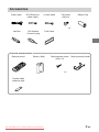
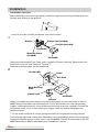
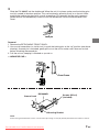
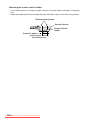
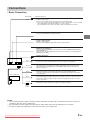
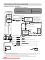
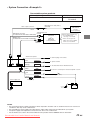
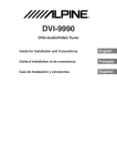
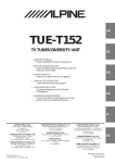
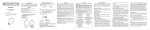
R
DVI-9990R
DVD-Audio/Video Tuner
Guide for Installation and Connections
English
Hinweise über die Installation und Anschlüsse
Deutsch
Guide d’installation et de connexions
Français
Guía de instalación y conexiones
Español
Guida all’installazione ed ai collegamenti
Italiano
Vägledning för montering och anslutningar
Svenska
Downloaded from Caradio-Manual.com Manuals
PRECAUTIONS
GUIDE FOR INSTALLATION AND CONNECTIONS
• Please read this GUIDE FOR INSTALLATION AND CONNECTIONS and the OWNER’S
MANUAL thoroughly to familiarize yourself with each control and function. We at ALPINE hope
that your new DVI-9990R will give you many years of listening enjoyment.
In case of problems when installing your unit, please contact your authorized ALPINE dealer.
Points to Observe for Safe Usage
• Read this manual carefully before starting operation and use this system safely. We cannot be
responsible for problems resulting from failure to observe the instructions in this manual.
• This manual uses various pictorial displays to show how to use this product safely and to avoid
harm to yourself and others and damage to your property.
Here is what these pictorial displays mean. Understanding them is important for reading this
manual.
• Meaning of displays
Warning
This symbol means important instructions. Failure to heed them can
result in serious injury or death.
Caution
This symbol means important instructions. Failure to heed them can
result in injury or property damage.
Warning
DO NOT DISASSEMBLE OR ALTER. Doing so may result in an accident, fire or electric shock.
USE THE CORRECT AMPERE RATING WHEN REPLACING FUSES. Failure to do so may
result in fire or electric shock.
MAKE THE CORRECT CONNECTIONS. Failure to make the proper connections may result in
fire or product damage.
USE ONLY IN CARS WITH A 12 VOLT NEGATIVE GROUND. (Check with your dealer if you are
not sure.) Failure to do so may result in fire, etc.
BEFORE WIRING, DISCONNECT THE CABLE FROM THE NEGATIVE BATTERY TERMINAL.
Failure to do so may result in electric shock or injury due to electrical shorts.
DO NOT ALLOW CABLES TO BECOME ENTANGLED IN SURROUNDING OBJECTS. Arrange
wiring and cables in compliance with the manual to prevent obstructions when driving. Cables or
wiring that obstruct or hang up on places such as the steering wheel, shift lever, brake pedals,
etc. can be extremely hazardous.
DO NOT SPLICE INTO ELECTRICAL CABLES. Never cut away cable insulation to supply power
to other equipment. Doing so will exceed the current carrying capacity of the wire and result in fire
or electric shock.
2
-EN
Downloaded
from Caradio-Manual.com Manuals
DO NOT DAMAGE PIPE OR WIRING WHEN DRILLING HOLES. When drilling holes in the
chassis for installation, take precautions so as not to contact, damage or obstruct pipes, fuel
lines, tanks or electrical wiring. Failure to take such precautions may result in fire.
DO NOT USE BOLTS OR NUTS IN THE BRAKE OR STEERING SYSTEMS TO MAKE
GROUND CONNECTIONS. Bolts or nuts used for the brake or steering systems (or any other
safety-related system), or tanks should NEVER be used for installations or ground connections.
Using such parts could disable control of the vehicle and cause fire etc.
DO NOT BLOCK VENTS OR RADIATOR PANELS. Doing so may cause heat to build up inside
and may result in fire.
KEEP SMALL OBJECTS SUCH AS BATTERIES OUT OF THE REACH OF CHILDREN. Swallowing them may result in serious injury. If swallowed, consult a physician immediately.
DO NOT INSTALL IN LOCATIONS WHICH MIGHT HINDER VEHICLE OPERATION, SUCH AS
THE STEERING WHEEL OR SHIFTLEVER. Doing so may obstruct forward vision or hamper
movement etc. and results in serious accident.
Caution
HAVE THE WIRING AND INSTALLATION DONE BY EXPERTS. The wiring and installation of
this unit requires special technical skill and experience. To ensure safety, always contact the
dealer where you purchased this product to have the work done.
USE SPECIFIED ACCESSORY PARTS AND INSTALL THEM SECURELY. Be sure to use only
the specified accessory parts. Use of other than designated parts may damage this unit internally
or may not securely install the unit in place. This may cause parts to become loose resulting in
hazards or product failure.
ARRANGE THE WIRING SO IT IS NOT CRIMPED OR PINCHED BY A SHARP METAL EDGE.
Route the cables and wiring away from moving parts (like the seat rails) or sharp or pointed
edges. This will prevent crimping and damage to the wiring. If wiring passes through a hole in
metal, use a rubber grommet to prevent the wire’s insulation from being cut by the metal edge of
the hole.
DO NOT INSTALL IN LOCATIONS WITH HIGH MOISTURE OR DUST. Avoid installing the unit
in locations with high incidence of moisture or dust. Moisture or dust that penetrates into this unit
may result in product failure.
Precautions
• Be sure to disconnect the cable from the (–) battery post before installing your DVI-9990R. This
will reduce any chance of damage to the unit in case of a short-circuit.
• Be sure to connect the color coded leads according to the diagram. Incorrect connections may
cause the unit to malfunction or damage to the vehicle’s electrical system.
• When making connections to the vehicle’s electrical system, be aware of the factory installed
components (e.g. on-board computer). Do not tap into these leads to provide power for this
unit. When connecting the DVI-9990R to the fuse box, make sure the fuse for the intended
circuit of the DVI-9990R has the appropriate amperage. Failure to do so may result in damage
to the unit and/or the vehicle. When in doubt, consult your ALPINE dealer.
• The DVI-9990R uses female RCA-type jacks for connection to other units (e.g. amplifier)
having RCA connectors. You may need an adaptor to connect other units. If so, please contact
your authorized ALPINE dealer for assistance.
Downloaded from Caradio-Manual.com Manuals
3-EN
Contents
PRECAUTIONS
2
Accessories
5
Installation
6
Connections
9
Connections with other equipments
10
• To use this unit, a Multimedia Manager (PXI-H990, sold separately) or DAC unit (DAI-C990,
sold separately) is required. This unit is powered by connecting with the PXI-H990 or DAIC990.
IMPORTANT
Please note the serial number of your unit in the space provided below and keep it as a permanent record. The serial number plate is located on the bottom of the unit.
SERIAL NUMBER:
INSTALLATION DATE:
INSTALLATION TECHNICIAN:
PLACE OF PURCHASE:
To prevent external noise from entering the audio system.
• Locate the unit and route the leads at least 10 cm away from the car harness.
• Keep the battery power leads as far away from other leads as possible.
• Connect the ground lead securely to a bare metal spot (remove any paint, dirt or grease if
necessary) of the car chassis.
• If you add an optional noise suppressor, connect it as far away from the unit as possible.
Your Alpine dealer carries various noise suppressors. Contact them for further information.
• Your Alpine dealer knows best about noise prevention measures so consult your dealer for
further information.
4
-EN
Downloaded
from Caradio-Manual.com Manuals
Accessories
Power cable
RCA Extension
cable (video)
S video cable
Flat screw
(M5 x 6)
Rubber Cap
x4
Hex Bolt
ISO Antenna
Convertor plug
Front frame
Parts for remote control
Remote control
Battery (AAA)
Reinforcement screw
(M3 x 12)
Remote control holder
x2
Double-sided
adhesive tape
Downloaded from Caradio-Manual.com Manuals
5-EN
Installation
Installation Location
Before deciding on the mounting location, check that opening and closing the display will not
hamper gear shifting in that position.
• Install at an angle of within 35 degrees from the horizontal.
1
Rubber Cap (Included)
Bracket
Hex Bolt (Included)
Dashboard
Mounting Sleeve
(Included)
DVI-9990R
Remove the Detachable Front Panel (refer to page 9 of Owner’s Manual). Remove the front
frame from main unit (see “Removal” on page 7).
Slide the mounting sleeve into the dashboard.
2
Hex Nut (M5)
Screw
★★
Metal Mounting
Strap
Bolt Stud
★
Ground Lead
DVI-9990R
Chassis
When your vehicle has the bracket, mount the long hex bolt onto the rear panel of the DVI9990R and put the rubber cap on the hex bolt. If your vehicle does not have the mounting
support, reinforce the monitor unit with the metal mounting strap (not supplied). Connect the
ground lead of the unit to a clean metal spot using a screw (★) already attached to the
vehicle’s chassis.
• For the screw marked ★★, use an appropriate screw for the chosen mounting location.
Connect each input lead coming from the product you are connecting with to the corresponding output lead coming from the left rear of the DVI-9990R. Connect all other leads of the DVI9990R according to details described in the “Connections” section.
6
-EN
Downloaded
from Caradio-Manual.com Manuals
3
Slide the DVI-9990R into the dashboard. When the unit is in place, make sure the locking pins
are fully seated in the down position. This can be done by pressing firmly in on the unit while
pushing the locking pin down with a small screwdriver. This ensures that the unit is properly
locked and will not accidentally come out from the dashboard. Install the Detachable Front
Panel.
Lock pin
Removal
1 Remove the DETACHABLE FRONT PANEL.
2 Use a small screwdriver (or similar tool) to push the locking pins to the “up” position (see above
drawing). As each pin is unlocked, gently pull out on the unit to make sure it does not re-lock
before unlocking the second pin.
3 Pull the unit out, keeping it unlocked as you do so.
< JAPANESE CAR >
Front Frame
DVI-9990R
Ground Lead
Screws (M5 x 6)
(Included)
★
Mounting Bracket
NOTE
Connect the ground lead of the unit to a clean metal spot using a screw (★) already attached to the vehicle's chassis.
Downloaded from Caradio-Manual.com Manuals
7-EN
Mounting the remote control holder
• If the remote control is in direct sunlight, remove it from the holder and keep it in the glove
box.
• When the holder cannot be mounted securely with Velcro tape, mount it by using screws.
Reinforcement Screws
Remote Control
Remote Control
Holder
Protective paper
Console Box etc.
8
-EN
Downloaded
from Caradio-Manual.com Manuals
Connections
• Basic Connection
Color Cable
Yellow
Cable Specifications
• Video output connector
Outputs a video signal.
Connects to the video input of the TV monitor you are linking with.
• There is a copy protect signal included in the video output signal, so that recording
with a VCR (Video Cassette Recorder) etc., is not possible.
Also, depending on the monitor, the picture may not be displayed correctly.
• IONBUS terminal
Connects with IONBUS compatible products.
• S video output terminal
Outputs a video signal.
Connects with ALPINE products with a S video input terminal.
• DVD Audio Link terminal
Connects with the DVD Audio Link terminal of the PXI-H990 Multimedia Manager or
DAI-C990 DAC unit.
(Connect when using a DVD audio disc. Remove the terminal cover and plug in the
DVD Audio Link cable).
• Antenna Receptacle
Blue
Orange
Black
Power supply unit
Red
Yellow
• Power Antenna Lead
Connect this lead to the +B terminal of your power antenna, if applicable.
• Illumination Lead
This lead may be connected to the vehicle’s instrument cluster illumination lead.
This will allow the backlighting of the DVI-9990R to dim whenever the vehicle’s
lights are turned on.
• Ground Lead
Connect this lead to a good chassis ground on the vehicle. Make sure the
connection is made to bare metal and is securely fastened using the sheet metal
screw provided.
• Switched Power Lead (Ignition)
Connect this lead to an open terminal on the vehicle’s fuse box or another unused
power source which provides (+)12V only when the ignition is turned on or in the
accessory position.
• Battery Lead
Connect this lead to the positive (+) post of the vehicle’s battery.
Fuse
(7.5A)
NOTES
• Do not install the power supply unit where it will be exposed to moisture such as under the floor mat or near the air
conditioner. This may cause a malfunction.
• Do not bundle the power supply unit cable with the audio cables. Noise may be induced into your system.
• The power supply unit temperature can become hot. This is not a malfunction.
Downloaded from Caradio-Manual.com Manuals
9-EN
Connections with other equipments
• System Connection <Example 1>
Connectable system products
IONBUS compatible monitor
Multimedia Manager or DAC unit
Ai-NET/IONBUS converter
Ai-NET compatible changer
DAB Receiver Box
System switch
“1 (SYSTEM)”
selected
*
IONBUS
compatible
monitor
(TMI-M990)
(sold separately)
TMI-M990
PXI-H990 or DAI-C990
KCI-500B
CHA-S634 or CHA-1214
TUA-T100DAB
DVD Audio Link cable
(Included with the PXI-H990 or DAI-C990)
To DVD Audio Link
terminal
Multimedia Manager
PXI-H990
or
DAC unit
DAI-C990
(sold separately)
To
IONBUS terminal
IONBUS
compatible
monitor box
*
*
IONBUS cable
(Included with the
TMI-M990)
To
IONBUS
terminal
To IONBUS
terminal
System switch (PXI-H990 only)
• Set to SINGLE when
connecting one PXI-H990.
• When connecting two PXIH990s, set the first to FRONT,
and the second to REAR.
When connecting the changer or
DAB Receiver Box, you must
use an Ai-NET/IONBUS converter
(KCI-500B).
IONBUS cable
(Included with the KCI-500B)
*
IONBUS cable
S video cable (Included)
*
To
IONBUS
terminal
Ai-NET/IONBUS
converter
(KCI-500B)
(sold separately)
*
Antenna Receptacle
Blue
POWER ANT
Orange
ILLUMINATION
<DVI-9990R>
Black
Red
Yellow
Power supply unit
GND
CD changer
(Ai-NET)
or
DAB
Receiver Box
(sold
separately)
To Ai-NET
connector
Ai-NET cable
(Included with CD changer or DAB Receiver Box)
To antenna plug of the vehicle
To power antenna
To the instrument cluster illumination lead
Connect to a metal part of chassis body with a screw.
IGNITION
BATTERY
Ignition Key
Fuse (7.5A)
Battery
NOTES
• Do not install the power supply unit where it will be exposed to moisture such as under the floor mat or near the air
conditioner. This may cause a malfunction.
• Do not bundle the power supply unit cable with the audio cables. Noise may be induced into your system.
• The power supply unit temperature can become hot. This is not a malfunction.
* For the Ferrite Core, refer to the Owner’s Manual of the product that the IONBUS cable is attached to.
10
-EN from Caradio-Manual.com Manuals
Downloaded
• System Connection <Example 2>
Connectable system products
PXI-H990 or DAI-C990
IONBUS incompatible
TV monitor
Multimedia Manager or DAC unit
External TV monitor
RCA Extension cable (video)
(Included)
Video output connector
External TV
monitor
(sold separately)
Yellow
To DVD Audio Link
DVD Audio Link cable
terminal
(Included with the PXI-H990 or DAI-C990)
Multimedia Manager
PXI-H990
or
IONBUS cable
DAC unit
(Included with the PXI-H990 or DAI-C990)
DAI-C990
(sold separately)
*
To IONBUS
terminal
System switch (PXI-H990 only)
• Set to SINGLE when
connecting one PXI-H990.
• When connecting two PXIH990s, set the first to FRONT,
and the second to REAR.
*
Antenna Receptacle
To antenna plug of the vehicle
Blue
POWER ANT
Orange
ILLUMINATION
To power antenna
To the instrument cluster illumination lead
Black
GND
Connect to a metal part of chassis body with a screw.
Red
IGNITION
Ignition Key
Yellow
Power supply unit
BATTERY
Fuse (7.5A)
Battery
NOTES
• Do not install the power supply unit where it will be exposed to moisture such as under the floor mat or near the air
conditioner. This may cause a malfunction.
• Do not bundle the power supply unit cable with the audio cables. Noise may be induced into your system.
• The power supply unit temperature can become hot. This is not a malfunction.
* For the Ferrite Core, refer to the Owner’s Manual of the product that the IONBUS cable is attached to.
Downloaded from Caradio-Manual.com Manuals
11-EN
R
ALPINE ELECTRONICS MARKETING, INC.
1-1-8 Nishi Gotanda,
Shinagawa-ku, Tokyo 141-0031, Japan
Phone 03-5496-8231
ALPINE ELECTRONICS OF AMERICA, INC.
19145 Gramercy Place, Torrance,
California 90501, U.S.A.
Phone 1-800-ALPINE-1 (1-800-257-4631)
ALPINE ELECTRONICS OF CANADA, INC.
7300 Warden Ave., Suite 203, Markham,
Ontario L3R 9Z6, Canada
Phone 1-800-ALPINE-1 (1-800-257-4631)
ALPINE ELECTRONICS OF AUSTRALIA PTY. LTD.
6-8 Fiveways Boulevarde Keysborough,
Victoria 3173, Australia
Phone 03-9769-0000
ALPINE ELECTRONICS GMBH
Frankfurter Ring 117, 80807 München,
Germany
Phone 089-32 42 640
ALPINE ELECTRONICS OF U.K. LTD.
Alpine House
Fletchamstead Highway,
Coventry CV4 9TW, U.K.
Phone 0870-33 33 763
ALPINE ELECTRONICS FRANCE S.A.R.L.
(RCS PONTOISE B 338 101 280)
98, Rue de la Belle Etoile, Z.I. Paris
Nord II, B.P. 50016, 95945 Roissy
Charles de Gaulle Cedex, France
Phone 01-48638989
ALPINE ITALIA S.P.A.
Viale C. Colombo 8, 20090 Trezzano
Sul Naviglio (MI), Italy
Phone 02-484781
ALPINE ELECTRONICS DE ESPAÑA, S.A.
Portal de Gamarra 36, Pabellón, 32
01013 Vitoria (Alava) - APDO 133, Spain
Phone 945-283588
Sankei Kikaku Co., Ltd.
1-13-38, Hinodai,
Hino, Tokyo, Japan
Designed by ALPINE Japan
Printed in Japan (S)
68-00323Z08-A
Downloaded from Caradio-Manual.com Manuals