1
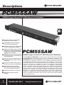
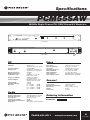
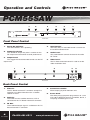
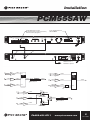
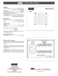
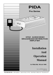
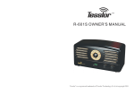
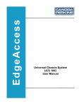
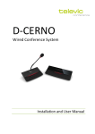
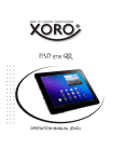
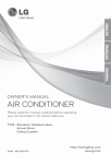
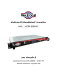
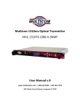
PCM55SAW
550MHz Single-Channel PLL SAW-filtered A/V Modulator
Installation and
Operation Manual
Ph:800-421-6511
www.picomacom.com
355 Parkside
Operation
Manual
Drive
San
Rev. 09/02
F
Ph: 818-493-4300 Toll Free: 800-
Safeguards
PCM55SAW
Important Information
Product Inspection
Inspect the equipment for shipping damage. Should any damage be discovered, immediately file a claim with the carrier.
Important Safety Instructions
To ensure proper installation and operation, take a moment to read this guide before proceeding with the installation. If
you have any questions or comments about the PCM55SAW modulator, please contact your dealer or have him contact
the PICO MACOM Service Center at the phone numbers at the bottom of the page
The lightning flash with arrowhead symbol, within
an equilateral triangle, is intended to alert the user
to the presence of uninsulated “dangerous voltage” within the product’s enclosure that may be of
sufficient magnitude to constitute a risk of electric
shock to persons.
The exclamation point within an equilateral triangle is intended to alert the user to the presence
of important operating and maintenance (servicing) instructions in the literature accompanying the
appliance.
WARNING:
TO REDUCE THE RISK OF FIRE OR ELECTRIC SHOCK, DO NOT EXPOSE
THIS APPLIANCE TO RAIN OR MOISTURE. DO NOT OPEN THE CABINET. REFER SERVICING TO QUALIFIED PERSONNEL ONLY.
CAUTION:
TO PREVENT ELECTRIC SHOCK DO NOT USE THIS (POLARIZED) PLUG WITH AN EXTENSION CORD RECEPTACLE OR OTHER OUTLET UNLESS THE BLADES CAN BE FULLY INSERTED TO PREVENT BLADE EXPOSURE.
ATTENCION:
POUR PREVENIR LES CHOCS ELECTRIQUES, NE PAS UTILISER CETTE FICHE POLARISEE AVEC UN PROLONGATEUR, UNE PRISE DE COURANT OU UNE AUTRE SORTIE DE COURANT, SAUF SI LES LAMES PEUVENT ETRE INSEREES A FOND SANS EN LAISSER AUCUNE PARTIE A DECOUVERT.
1. Read Instructions: All safety and operating instructions should be
read before the appliance is operated.
6. Do Not Use Attachments: Use of attachments not recommended by the
manufacturer may cause hazards.
2. Retain Instructions: The safety and operating instructions should be
retained for future reference.
7. Water and Moistures: Do not use this product near water - for
example, near a bathtub, washbowl, kitchen sink, laundry tub, in a wet
basement, or near a swimming pool - and the like.
3. Heed Warnings: All warnings on the appliance should be adhered
to.
4. Follow Instruction: All operating and user instructions should be
followed.
5. Cleaning: Unplug this appliance from the wall outlet before cleaning. Use a damp cloth for cleaning. Do not use liquid cleaners or
aerosol cleansers.
2
Rev. 09/02
Ph:800-421-6511
8. Accessories: Do not place this product on an unstable cart, stand,
tripod, bracket, or table. The product may fall, causing serious injury
to a child or adult, and serious damage to the appliance.
9. Ventilation: This video product should never be placed near or over a
radiator or heat register. This video product should not be placed in a built-in
installation such as a bookcase or rack unless proper ventilation is provided or
the manufacturer’s instructions have been adhered to. Any slots or opening
in the cabinet are provided for ventilation. To ensure reliable operation of the
www.picomacom.com
Safeguards
PCM55SAW
video product and to protect it from overheating, these openings must not be
blocked or covered. Openings should never be blocked by placing the product
on a bed, sofa, rug, or other similar surface.
10. Grounding or Polarization: This video product is equipped with
either a three prong plug for 110 VAC use or a two prong flat blade
220 volt type plug. Each type is to be inserted into only the type of
receptacle for which they specifically designed. Do not cut off the
round grounding pin in order to be able to fit into a two prong receptacle as this could cause injury and will void the warranty.
11. Power Sources: This product should be operated only from the
type of power source indicated on the marking label. If you are not
sure of the type of power supplied to your home, consult your appliance dealer or local power company.
12. Power-cord Protection: Power-supply cords should be routed so
they are not likely to be walked on or pinched by items placed upon
or against them. Pay particular attention to cords and plugs, convenience receptacles, and the point where they exit from the appliance.
13. Lightning: For added protection for this product during a lightning storm, or when it is left unattended and unused for long periods
of time, unplug it from the wall outlet.
14. Power Lines: An outside antenna system should not be located
in the vicinity of overhead power lines, other electric light or power
circuits, where it can fall into such power lines or circuits. When
installing an outside antenna system, extreme care should be taken to
keep from touching power lines or electrical circuits, as contact with
them may be fatal.
15. Overloading: Do not overload wall outlets and extension cords as
this can result in risk of fire or electric shock.
16. Object and Liquid Entry: Never push objects of any kind into this
product through openings as they may touch dangerous voltage
points or short-out parts that could result in a fire or electric shock.
Never spill liquid of any kind on the product.
17. Servicing: Do not attempt to service this product yourself as
opening or removing covers may expose you to dangerous voltage or
other hazards. Refer all servicing to qualified service personnel.
18. Damage Requiring Service: Unplug this product from the wall
outlet and refer servicing to qualified service personnel under the following conditions:
a. When the power-supply cord or plug is damaged.
b. If liquid has been spilled, or objects have fallen into the product.
c. If the product has been exposed to rain or water.
d. If the product does not operate normally by following the operating instruction. Adjust only those controls that are covered by the
operating instructions. An improper adjustment may result in damage and will often require extensive work by a qualified technician to
restore the product to its normal operation.
e. If the product has been dropped or the cabinet has been damaged.
f. When the product exhibits a distinct change in performance - this indicates
a need for service.
19. Replacement Parts: When replacement parts are required, be sure the
service technician has used replacement parts specified by the manufacturer
or have the same characteristics as the original parts. Unauthorized substitutes may result in fire, electric shock or other hazards.
20. Safety Check: Upon completion of any service or repairs to this
product, ask the service technician to perform safety checks to determine that the product is in proper operating conditions.
21. Outdoor Antenna Grounding: Before attempting to install this
product, be sure the antenna or cable system is grounded so as to
provide some protection against voltage surges and built-up static
charges.
a. Use No.10 AWG (5.3mm) copper, No.8 AWG (8.4mm (aluminum,
No.7 AWG (10mm) copper-clad steel or bronze wire or larger, as
ground wire.
b. Secure antenna lead-in and ground wires to house with stand-off
insulators spaced from 4 feet (1.22m) to 6 feet (1.83m) apart.
c. Mount antenna discharge unit as close as possible to where lead-in
enters house.
d. A driven rod may be used as the grounding electrode where
other types of electrode systems do not exist. Refer to the National
Electrical Code, ANSI/NFPA 70-1984 for information.
e. Use jumper wire not smaller than No.6 AWG (13.3mm ) copper or
equivalent, when a separate antenna grounding electrode is used.
NOTE TO THE CATV SYSTEM INSTALLER
THIS REMINDER IS PROVIDED TO CALL THE CATV
SYSTEM INSTALLER’S ATTENTION TO ARTICLE 820
- 22 OF THE NEC THAT PROVIDES GUIDELINES
FOR PROPER GROUNDING AND, IN PARTICULAR,
SPECIFIES THAT THE CABLE GROUND SHALL BE
CONNECTED TO THE GROUNDING SYSTEM OF THE
BUILDING, AS CLOSE TO THE POINT OF CABLE
ENTRY AS PRACTICAL.
Ph:800-421-6511
3
355 Parkside Drive
San F
www.picomacom.com
Rev. 09/02
Ph: 818-493-4300 Toll Free: 800-
Descriptions
PCM55SAW
550MHz Single-Channel PLL SAW-filtered A/V Modulator
90-Channel Range 5.75-550 MHz
(CATV T7-T13, 2-78, 95-99)
Full 55dBmV output for optimum
carrier-to-noise performance
In-band carrier-to-noise ratio >62dB
ensures superior picture quality
Highly accurate DIP switch controlled
digital phase-locked loop (PLL) design
guaranteesprecisefrequencylockingfor
solid drift-free operation
SAW filtered IF for superior adjacent
channel performance enables drop-in
channel expansion
PCM55SAW
Easy lab retuning of output filter for
reduced inventory of spares and less
down time
Front panel controls and test point
enables easy setup and monitoring
IRC and HRC offset capability
allows for easy frequency settings
in systems using offset channels
Auxiliary AC outlet for convenience
Optional PAL format channels
available
4
Rev. 09/02
Ph:800-421-6511
550MHz Single-Channel PLL SAW-filtered A/V Modulator
The Pico Macom PCM55SAW is a professional grade microprocessor controlled
phase-locked-loop synthesized single channel audio-video modulator. The
PCM55SAW provides a full 55dBmV minimum output from sub-band channels
T7 through T13, and CATV channels 2 to 78 including channels 95 to 99 while
accommodating HRC and IRC offset frequencies (5.75-550MHz). The unit is field
re-tunable within band via internal dip-switch channel selection and minimum
output filter retuning. This modulator is used in more heavily channel-loaded
systems and where cost effective expansion up to 550MHz is desired and
greater frequency stability and higher spurious free adjacent channel performance is required. Its phase-locked-loop frequency control, and superior SAW
filtering enhances stability, minimizes adjacent channel interference and assures
accurate and spurious free output. Superior out-of-band carrier-to-noise
performance is achieved through band-pass filtering at the output amplifier. The
modulator is shipped with all internal adjustments preset. FCC Docket 21006
offsets are standard. Pico Macom backs up this product with its industry leading
5-year limited warranty.
www.picomacom.com
Specifications
PCM55SAW
550MHz Single-Channel PLL SAW-filtered A/V Modulator
PCM55SAW
550 MHz PLL Saw-Filtered Audio/Video Modulator
OUTPUT TEST
POWER
AUDIO LEVEL
AURAL CARRIER
OUTPUT LEVEL
VIDEO LEVEL
CHANNEL
-30 dB
Front View
RF OUT
VIDEO IN
120VAC
60Hz 10W
AUDIO IN
600W MAX
Rear View
Video
RF
Channels: Frequency Range: Output Level: Output Impedance: Output Return Loss: Audio/Video Ratio: Frequency Stability: Spurious Output: C/N (In-Band): C/N (Out-of Band): Rejection: 90 Channels
(CATV T7-T13, 2-78, 95-99)
5.75-550 MHz
55 dBV min., 58 dBmV typ. adjustable from front panel
75 Ohms
-15 dB
Adjustable -7 to -22 dB
below video carrier
±10 kHz (±5 kHz in
aeronautical band)
60 dB below video carrier with A/V ratio @ -15 dB
>60 dB
>65 dB
Fv - 1.5 MHz >-60 dB
Fv - 4.5 MHz >-63 dB
Fa + 1.5 MHz >-63 dB
Fa + 4.5 MHz >-63 dB
Input Level:
Input Level Range:
Input Type:
Frequency Response:
Differential Gain:
Differential Phase:
Hum and Noise: Video Signal to Noise:
1.0 V p-p for 87.5% mod.
0.5 V p-p to 1.5 V p-p
Clamped video neg. sync
±1.5 dB, DC to 4.2 MHz
<5% (10 to 90% APL)
>5° (10 to 90% APL)
-60 dB @ 87.5% modulation
-60 dB minimum (weighted)
General
Power Input: 120 VAC @ 60 Hz
Operating Temperature: -10°C to 50°C
Dimensions: 19˝(L) x 3˝(D) x 13/4˝(H)
Weight: 3.5 lbs.
Connectors: “F” Type
Audio
Frequency Response: Harmonic Distortion: Preemphasis: Signal to Noise Ratio: Audio Baseband Impedance:
Input level:
±0.4 dB @ 50 Hz to 15 kHz
0.5% @ 50 Hz to 15 kHz
75 microseconds
60 dB
600 Ohms
0.5 V p-p for 25 kHz deviation
Ordering Information
PCM55SAW-
Ph:800-421-6511
Channel
5
355 Parkside Drive
San F
www.picomacom.com
Rev. 09/02
Ph: 818-493-4300 Toll Free: 800-
Operation and Controls
PCM55SAW
1
PCM55SAW
2
3
4
5
6
550 MHz PLL Saw-Filtered Audio/Video Modulator
OUTPUT TEST
POWER
OUTPUT LEVEL
AURAL CARRIER
AUDIO LEVEL
VIDEO LEVEL
CHANNEL
-30 dB
Front View
Front Panel Control
1. Power On Indicator:
The LED indicates unit is operating.
2. Output Test Point:
The -30 dB RF output test point is used to set the RF output level and monitor channel performance.
3. Output Level:
This rugged PC Board mounted control sets the RF output level.
1
2
VIDEO IN
AUDIO IN
4.
Aural Carrier:
The heavy duty PC mounted control is used to set the audio modulation level.
5. Audio Level:
This potentiometer controls the level of the audio RF carrier.
6. Video Level:
The PC Board mounted control is used to set the video modulation level.
3
4
RF OUT
5
120VAC
60Hz 10W
600W MAX
Rear View
Back Panel Control
1. Video In:
The PC Board mounted “F” connector accepts the negative sync video information from a satellite receiver or VCR.
2. Audio In:
The audio from the satellite receiver or VCR is
connected to this PC Board mounted F connector.
3.
4.
Convenience Outlet:
Allows looping of power between units.
5.
Power Cord:
The three prong type power plug connects to a 120 VAC, 60 Hz electrical output or if 220VAC, 60 Hz, a two prong flat blade type is used.
RF Out:
The modulated output signal is available on this PC Board mounted “F” connector.
6
Rev. 09/02
Ph:800-421-6511
www.picomacom.com
Installation
PCM55SAW
Audio Output Connection:
Center Conductor to Mono+(Positive)
Shield to Mono-(Negative)
From Satellite Antenna
950-1750MHz
+
+
DATA
_
+
LANGUAGE
CLOCK
_
GND
+
L
+
+
VIDEO
OUT
AUDIO OUTPUT LEVEL
AUDIO OUTPUT
MONO
LEFT
RIGHT
_
_
_
+
+
+
R
MONO
RF IN
950-1450
MHz
70 MHz
COMPOSITE
OUT
18V 250mA
LNB POWER
OUT
VIDEO
LEVEL
IN
INV
OUT
H
NOR
ON
V
FUSE
AC25OV
1/2A
OFF
117V
.35A
60Hz
PR4200IRD SATELLITE RECEIVER
VIDEO IN
AUDIO IN
+
+
+
RF OUT
VIDEO IN
120VAC
60Hz 10W
AUDIO IN
+
CAUTION
!
RISK OF ELECTRIC SHOCK
DO NOT OPEN
+
+
600 VA MAX
PCM55SAW MODULATOR
RT OUT to TV or
Distribution System
V
A
RF
IN
PCM55SAW
+52dBmV
Ch. 2
V
A
PHC-12G
-16dB
+10dBmV
SP600
+52dBmV
Ch. 3
+36dBmV
6dB PAD
CA-30RK550
PCM55SAW
+52dBmV
Ch. 2
CHC16/860
+10dB
to
+60dBmV
RF
IN
+10dBmV
RF
IN
+14dBmV
XBS
+10dBmV
SP600
+52dBmV
Ch. 3
+58dBmV
ATTENUATOR PAD
RF
IN
+14dBmV
+10dBmV
XBS
+52dBmV
Ch. 4
+52dBmV
PAD
Ch. 4
ATTENUATOR PAD
V
A
Ch. 2
PCM55SAW
PCM55
+50dBmV
+43dBmV
Ch. 4
RF
IN
+10dBmV SP860
+50dBmV
EVEN CHANNELS
+36dBmV
Ch. 3
RF
IN
+14dBmV
XBS
+10dBmV
+50dBmV
6dB PAD
CA-30RK550
+60dBmV
ATTENUATOR PAD
+43dBmV
ODD CHANNELS
Ph:800-421-6511
7
355 Parkside Drive
San F
www.picomacom.com
Rev. 09/02
Ph: 818-493-4300 Toll Free: 800-
Warranty
Important Information
Five-Year Limited Warranty*
Pico Macom, Inc. warrants to the original purchaser this product shall be free of defects in material and craftsmanship
with only the limitations or exclusions set out below.
During the warranty period Pico Macom Inc. or an authorized Pico Macom service facility will provide free of charge,
the parts and labor necessary to correct defects in material and workmanship.
Warranty Duration
This warranty shall terminate five years* from the original date of purchase of the product or at a time the product is:
1. Misused or damaged due to neglect or improper installation
2. Modified
3. Repaired by someone other than the warrantor
4. Sold by the original purchaser
Statement of Remedy
To obtain warranty service, contact the salesperson where the product was obtained. You will be issued a Return
Authorization (RA) number, which will be used to track your product.
Be prepared to provide:
1. The model number and channel number of the product
2. The serial number of the product
3. The date of purchase
4. A specific identification of the problem
Deliver the products to Pico Macom Inc. or ship the products in the original packing material at the address at the
bottom of the page. Include satisfactory evidence of the date of purchase.
Products without the RA number clearly indicated on the shipping label will not be accepted by Pico Macom Inc..
The foregoing constitutes the Pico Macom, Inc. entire obligation with respect to this product and the original purchaser
and any user or owner shall have no other remedy and no claim for incidental or consequential damages. Some states
do not allow limitations on how long an implied warranty lasts or do not allow the exclusions or limitation of incidental or
consequential damages, so the above limitation and exclusion may or may not apply to you.
This warranty gives you specific legal rights, and you also have rights, which vary from state to state.
* One Year Warranty if sold outside the U.S.A.
Operation
Manual
Rev. 09/02
Ph:800-421-6511
www.picomacom.com