1
NAVAL POSTGRADUATE SCHOOL
Monterey
,
California
THESIS
DESIGN AND IMPLEMENTATION OF A
TOKEN-RING FIBER OPTIC LOCAL AREA NETWORK
INTERFACE MODULE
by
Mary
L.
Anderson
September 1989
Thesis Advisor:
John P. Powers
Approved for public release; distribution is unlimited
T247162
UNCLASSIFIED
SECURITY CLASSIFICATION QF THIS PAGE
REPORT DOCUMENTATION PAGE
REPOR-' SECURITY CLASSIFICATION
'la
RESTRICTIVE
MARKINGS
UN-CLASSIFIED
SECURITY CLASSIFICATION AUTHORITY
2a
2b DECLASSIFICATION
Approved for public release;
distribution is unlimited
'DOWNGRADING SCHEDULE
PERFORMING ORGANIZATION REPORT NUMBER{S)
4
NAME OF PERFORMING ORGANIZATION
6a
ADDRESS
and
(Ofy, Stafe,
MONITORING ORGANIZATION REPORT NUMBER(S)
5
6b OFFICE
(If
INaval Postgraduate School
6c
DISTRIBUTION /AVAILABILITY OF REPORT
3
SYMBOL
7a
applicable)
ZIP Code)
NAME OF MONITORING ORGANIZATION
Naval Postgraduate School
62
7b
Monterey, California 93943-5000
ADDRESS
(C/ty, state,
and Z/P Code;
Monterey, California 93943-5000
PROCUREMENT INSTRUMENT IDENTIFICATION NUMBER
ADDRESS
8c.
(City, State,
and ZIP Code)
10
SOURCE OF FUNDING NUMBERS
11 TITLE f/nc/ude secunty c/ass//,cat,onj
DESIGN AND IMPLEMENTATION OF A TOKEN-RING FIBER
OPTIC LOCAL AREA NETWORK INTERFACE MODULE
PERSONA. AUTHOR(S)
12
ANDF.R>^QN.
Mary
14
DATE OF REPORT
(Year,
Month, Day)
15
PAGE COUNT
43
1989 September
vlews expressed in this thesis are those of the
author and do not reflect the official policy or position of the Department of Defense or the U.S. Government.
SUPPLEMENTARY NOTATioNThe
16
COSATi CODES
18
SUBJECT TERMS {Continue on reverse
if
necessary
Token-Ring; fiber optic;
and
identify by block
number)
local area network
(LAN)
ABSTRACT (Continue on
19
reverse
if
necessary and identify by block number)
This thesis describes the design and implementation of a token-ring
fiber optic local area network (LAN) interface module.
The token-ring
protocol implementing the IEEE 802.5 standard is reviewed.
The initial
LAN electrical signal operating at 4 Mbps is provided by a LAN adapter
card based on the TMS380 chipset developed for twisted pair copper wire.
This design features analog implementations of both the input electrical
circuitry of the optical transmitter and output electrical circuitry of
the optical receiver.
Successful LAN communications over the fiber optic
link are described.
DISTRIBUTION /AVA.LABILITV OF ABSTRACT
20
CS JNCLASSIFIED/UNLIMITED
NAME OF RESPONSIBLE
John P. Powers
22a
DDForm
1473,
JUN 86
D
INDIV
SAME AS RPT
M ABSTRACT SECURITY CLASSIFICATION
UNCLASSIFIED
22b TELEPHONE (/nc/ude Area Code;
408-646-2082
Previous editions are obsolete
S/N 0102-LF-014-6603
22c
OFFICE
SYMBOL
62Po
SECURITY CLASSIF CATION OF THIS PAGE
I
UNCLASSIFIED
Approved for public release; distribution is unlimited
DESIGN AND IMPLEMENTATION OF A TOKEN-RING
FIBER OPTIC LOCAL AREA NETWORK
INTERFACE MODULE
by
Mary L. .Anderson
Lieutenant, United States Navy
B.A.
Central University of Iowa, 1978
,
Submitted in partial fulfillment of the
requirements for the degree of
MASTER OF SCIENCE IN ELECTRICAL ENGINEERING
from the
NAVAL POSTGRADUATE SCHOOL
September 1989
ABSTRACT
This thesis describes the design and implementation of a
token-ring
module.
standard
fiber optic
local
area network
(LAN)
interface
The token-ring protocol implementing the IEEE 802.5
is
operating at
reviewed.
4
The
initial
LAN
electrical
signal
Mbps is provided by a LAN adapter card based
on the TMS380 chipset developed for twisted pair copper wire.
This design features analog implementations of both the input
electrical circuitry of the optical transmitter and output
electrical circuitry of the optical receiver.
Successful LAN
communications over the fiber optic link are described.
TABLE OF CONTENTS
I
II
III
IV.
V.
INTRODUCTION
1
A.
GENERAL
1
B.
THESIS OBJECTIVES
2
C.
THESIS ORGANIZATION
2
BACKGROUND
4
A.
LANS AND THE ISO MODEL
4
B.
TOKEN RING PROTOCOL
5
C.
TMS380 LAN ADAPTER CHIPSET.
13
DESIGN REQUIREMENTS
A.
MICROCOMPUTER SYSTEM CONFIGURATION
B.
DESCRIPTION OF SIGNAL TO BE MODELED
DESIGN DESCRIPTION AND EVALUATION
16
16
18
23
A.
DESIGN APPROACH
23
B.
THE TRANSMITTER CIRCUIT DESIGN
24
C.
THE RECEIVER CIRCUIT DESIGN
27
D.
DESIGN EVALUATION
29
CONCLUSIONS AND RECOMMENDATIONS
36
A.
CONCLUSIONS
36
B.
RECOMMENDATIONS
36
REFERENCES
DISTRIBUTION LIST
37
„
38
DUDLEY
HAVAL
KI
FO;s.
MOUTEBUY.
I.
A.
C
INTRODUCTION
GENERAL
During the past few years, token-passing ring interface
techniques have risen as a viable technology for local area
network
(LAN)
Simultaneously,
applications.
optical
fiber
has become the preferred transmission medium for use in longhaul communication systems.
within
a
local
area
The present use of optical fiber
network
is
limited
predominately
to
networks with a bus topology and utilizing either Carrier
Sense Multiple Access with Collision Detection (CSMA/CD)
token passing protocols [Ref.
l:p.
238],
or
Within token ring
LANs, present use of fiber optic cable is limited to backbone
applications which link individual LANs together while fiberto-terminal equipment is rarely
A
broadened
use
of
fiber
implemented.
within
token-ring
[Ref. 2:p. 74]
LANs
will
be
recognized upon final completion of the Fiber Distributed Data
Interface (FDDI) standards.
These standards describe a fiber
optic token-ring LAN that operates at 100 Mbps and employs a
redundant,
counter-rotating,
dual-ring topology.
The FDDI
standards draw heavily from the existing IEEE 802.5 standard
for dual twisted-pair copper wire.
3,
[Ref.
2:p.
78]
Reference
IEEE 802.5, is the accepted standard for the token-passing
LAN, operating at
4
Mbps and employing a single ring topology.
The FDDI standards deviate from the IEEE 802.5 standard only
when
required
by
its
higher data
rate
the
and
intrinsic
differences between electrical and optical signals.
B.
THESIS OBJECTIVES
The subject of this thesis is a hardware design of a fiber
optic LAN interface module.
identify and model
token-ring LAN.
the
The initial objective was to
electrical
signal
produced by the
The next objective was to design and build
a fiber optic link,
and then to pass the modeled signal over
the link and correctly recover the signal at the distant end.
The
final
objective was to transparently insert the
optic link into the LAN.
fiber
A transparent insertion is being
defined here as conforming to the following criteria:
o
C.
meet existing standards of Reference
dual twisted-pair copper wire,
3
developed for
o
not adversely affect the software protocol, and
o
allow the LAN to communicate over the fiber optic link.
THESIS ORGANIZATION
Chapter II provides the necessary background to ensure a
baseline
knowledge
of
local
area
networks
with
emphasis on token-ring access and implementation.
special
Chapter
III presents design specifications and thoroughly describes
the existing network system components.
Chapter IV deals with
detailed design, construction, and operation of the hardware
that was built.
In addition, Chapter IV
also
presents the
design
followed
V.
performance
by
when implemented
conclusions
and
within
the
LAN,
recommendations in Chapter
BACKGROUND
II.
A.
LANS AND THE ISO MODEL
area
Local
networks
include
data
and
computer
communication elements that are geographically confined to
being less than 10 kilometers apart and generally utilizing
a shared transmission media.
In
relation
to
the
[Ref.
Open
4: p.
System
6]
Interconnection
(ISO)
model, local area network standards and protocols are applied
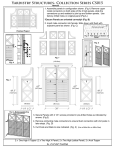
at the lowest two layers as depicted in Figure
1.
The lowest
layer, the physical layer, defines the actual electrical and
mechanical connections.
APPLICATION
(7)
PRESENTATION
(6)
SESSION
(5)
TRANSPORT
(4)
NETWORK
(3)
DATA
(2)
LINK
PHYSICAL
The next layer, the Data Link layer.
LOGICAL LINK CONTROL (LLC)
MEDIUM ACCESS CONTROL (MAC)
(1)
Figure
1.
ISO Reference Model
is divided into the Medium Access Control
Link Control (LLC) sublayers.
and Logical
(MAC)
Together these sublayers define
the way that data is formatted for transmission and how access
to
network
the
controlled
is
[Ref:5:p.
There
1-3].
are
several different MAC sublayers depending on the LAN topology
and protocol.
B.
Some examples of MAC technology include:
o
star-wired ring topology using token passing access,
o
bus topology using CSMA/CD access, and
o
bus topology using token passing access.
TOKEN RING PROTOCOL
Although this research is confined predominately to the
physical
layer,
understanding
reasonable
a
the
of
MAC
technology of the star-wired ring topology using token passing
protocol is considered essential.
token
access
control
Figure
mechanism.
A
illustrates the
2
token
an
is
access-
granting, unique symbol sequence that circulates from station
to station on the ring.
In our system, the token is
3
bytes in length and consists
of: a starting delimiter field (SDEL)
(AC)
,
fields
,
and an ending delimiter field
is
JKOJKOOO.
1
byte
This
synchronization.
Manchester
transition.
code
in
(The
J
violations
Each of these
.
sequence is
The SDEL symbol
length.
pattern
an access control field
(EDEL)
is
and
used
K
that
by
the
symbols
do
not
adapter
are
have
for
deliberate
a
mid-bit
Manchester coding and these symbols are discussed
in more detail in Chapter III.)
the token indicator bit,
6
The AC field byte contains:
bits for priority indication and
The token indicator
reservation, and the monitor count bit.
The
bit differentiates between a free token and a frame.
priority
indication
and
reservation
bits
mechanism within the token-ring protocol
3
the
The priority levels are limited to
access on the ring.
through
provides
for prioritizing
as are the reservation levels.
bit is used by the Active Monitor.
The monitor count
An Active Monitor is the
station on the ring that has the responsibility for ensuring
normal ring operation.
The Active Monitor receiving a
1
in
the monitor count bit indicates a frame or reserved token was
not properly removed from the ring.
The Active Monitor then
purges the ring and generates a free token.
The EDEL symbol
sequence
is
JKIJKIOX.
sequence is an error detected indicator.
no error and
1
Bit
7
this
of
This bit is
for
The EDEL, like the SDEL,
for error detected.
is used by the adapter for synchronization.
The
possessor
transmission media.
of
the
token
has
exclusive
use
of
the
The single token circulates on the ring,
thereby giving each station on the net an opportunity to
transmit data when it receives the token.
a
to
transmit,
captures the token and changes
it
status to "busy".
indicator
bit
Figure 2a depicts
When a station has data
free token circulating the ring.
the
token
This is accomplished by changing the token
in the
AC
field
of
the token from
to
1.
(A one
in the token indicator bit signifies a frame vice a
free token.)
The station then transmits a data frame.
The data frame format is strictly defined by the token-
ring protocol and consists of the following fields listed in
order of ring transmission:
o
Starting Delimiter field (SDEL)
o
Access Control field (AC)
o
Frame Control field (FC)
o
Destination Address (DA)
o
Source Address (SA)
o
Information field (data)
o
Frame Check Sequence field (FCS)
o
Ending Delimiter (EDEL)
o
Frame Status field (FS)
,
,
and
The bit sequence of the SDEL, AC and EDEL fields in a data
frame is identical to the respective fields of a token with
the exception of the set token indicator bit as previously
discussed.
The FC field is
1
byte in length and indicates the frame
type as a MAC control frame or non-MAC control frame.
MAC
control frames execute the MAC layer protocol as discussed in
Reference
3.
This protocol implements a comprehensive set of
problem determination,
resolution,
and reporting functions.
Through the MAC frames, the ring communication problems are
rapidly diagnosed and corrected.
MAC frames originate from
and are processed by the station adapters.
Therefore,
the
operation of MAC protocol is completely transparent to the
individual host computers and provides a functionally reliable
LAN.
Source and destination address fields are each
length.
6
bytes in
These fields identify the frame's originator and the
frame's intended receiver.
The information field contains the data to be transmitted.
The maximum length of this field is 4027 bytes.
The Frame Check sequence field contains a 32-bit cyclic
redundancy code (CRC) that is used to protect the FC, DA, SA
and information fields.
the CRC that
transmitted.
is
The frame's source station provides
used in the FSC
field when the
frame
is
Each adapter calculates the CRC by a polynomial
that is serially accumulated as the frame is transmitted or
received.
The received CRC in the FSC field is compared to
the adapter's calculated value to verify that the frame was
received without error.
The frame status field is
1
byte in length.
This field
indicates to the frame source whether the frame destination
address was recognized and if the frame was copied by the
destination station.
Figure 2b depicts station A, after taking possession of
the token, transmitting a data frame.
is not the possessor of the token,
A
receiving
station
reads
the
8
Each station, when it
functions as a repeater.
frame
and
determines
its
destination.
If the
frame destination is not the received
station, the station repeats (retransmits)
the frame.
This
repeater function is depicted in Figure 2c.
Figure
depicts
2d
destination.
station
acknowledges receipt.
frame's
intended
This acknowledgement is accomplished
by setting the frame copied (FC)
status field to
to
the
as
C
The destination station copies the data and
retransmit
acknowledged,
the
it
indicator bits in the frame
The destination station is also required
1.
frame.
is the
Once
data
the
received
is
and
responsibility of the frame source
station to remove its data from the ring and
generate a new
token.
Figure 2e shows station A completing the transmission
of the
frame.
Figure 2f depicts the originating station A
removing its data from the ring and generating the new token.
[Ref.
1-5 to 3-16]
5:pp.
Since all stations wait for the token to transmit data,
and the station possessing the token has exclusive use of the
transmission
media,
collisions
(two
attempting to transmit simultaneously)
protocol,
therefore,
produces
a
or
more
stations
do not occur.
reliable
This
deterministic
approach to LAN communications and eliminates the performance
uncertainties of collision-based LAN protocols.
(a)
(b)
Circulating token, any station can transmit
upon receiving the token
Station A seizes token, transmits frame of
data addressed to station C
Figure
2.
Token Access Control for Message
10
(c)
(d)
station B receives frame, checks address
and repeats frame
Station C receives frame, recognizes address
acknowledges receipt and repeats data
Figure
2.
(cont.)
11
(e)
Station D repeats frame
COPIED FRAME
FREE TOKEN
(f)
Station A receives acknowledgement and repeated data,
transmits free token (only)
the cycle repeats
,
Figure
2.
12
(cont.)
C.
TMS38
LAN ADAPTER CHIPSET
Texas Instruments and IBM jointly developed the integrated
architecture of TMS380 chipset for connecting equipment to a
token-ring LAN.
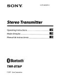
Figure
is a block diagram of the TMS380
3
chipset consisting of five integrated circuit devices.
The TMS3803
system
interface
chip provides the
(SIF)
means to transfer data between the LAN adapter environment
The SIF asynchronously connects the host
and the host system.
system bus, operating at data rates up to
LAN adapter bus, operating at
6
Mbytes/sec, to the
5
Mbytes/sec.
The SIF provides
both direct memory access (DMA) and direct I/O (DIO) transfers
between these buses.
A 16-bit high performance CPU with on-chip buffer RAM is
contained
on
dedicated
CPU
the
and
communications
TMS38010
RAM were
designed
to
processor.
minimize
the
The
LAN
adapter overhead burden on the host system by handling all
the non-real time LAN functions.
These functions include:
preforming adapter
controlling the operations of the SIF,
bring-up diagnostics,
the
executing the MAC protocol,
frame buffers with the on-chip RAM,
managing
and maintaining a
working storage space also with the on-chip RAM.
The
TMS38020
protocol
hardware-based protocol
8
02.5
standard.
These
handler
performs
the
real-time
functions compatible with the IEEE
functions
include:
differential
Manchester encoding and decoding of data, recognizing frame
addresses, and capturing free tokens.
13
The protocol handler
also contains a on-chip ROM of 16K bytes of software used by
the communication processor.
Jointly, the two chips TMS38051 and TMS38052 are the ring
Collectively, they connect the station to the LAN
interface.
through separate transmit and receive channel
In
pairs.
addition, they provide the phantom drive signal to physically
insert the station into the ring.
a
DC voltage
on the
The phantom drive impresses
transmit pair.
(This
DC voltage
is
transparent to the station's transmitted data, hence, the name
"phantom"
.
The impressed DC voltage is used by the wiring
)
concentrator
control
to
serially into the ring.
relays
that
insert
the
station
Loss or absence of the phantom drive
voltage results in the station being bypassed or removed from
the ring.
Use
chipset,
5:p.
1-8]
token
ring
[Ref.
of
a
LAN
adapter card,
based
on
this
eliminates incompatibilities that could arise even
at the chip level.
This ensures
interoperability and LAN
connectivity within a token-ring network.
In summary, this chapter supplied a baseline knowledge of
token-ring LANs.
This baseline included: a review of the ISO
model as it related to token-ring LANs, a discussion of the
token-ring protocol, and a description of the TMS380 chipset.
Chapter
III
presents
baseline concepts.
the
design
requirements
using
these
5
z
<
>
CO
o
CE
cc
f-
-
n
-
1
UJ
U
ui
n
±
to
oc
a:
UJ
o
00
n
to
5
»1
4
t
C/)
Q.
D
m
^
C
Ul
t
<
Q
<
2
Q.
<
<
(/)
Q
Z
<
o
CO
5
Z
ogo:
t-
o
o < to
00 u w
-
C/3
H
2
:?
5
(J
r
°8S
u il
o
^
«i
>- CL
^
\j
1
cc
°-
o
u
o
^J
S^i
00
jtl
u
7"^
1
r
to^^
w ^
1 > 'O
Figure
3
TMS380 LAN Adapter Chipset Block Diagram
[from Ref. 5:p.
1-7]
III. DESIGN REQUIREMENTS
A.
MICROCOMPUTER SYSTEM CONFIGURATION
Figure
is
4
a
block diagram showing the microcomputer
system that provided the basic token ring LAN configuration
This system consisted of:
for this thesis.
o
two IBM XT clones,
o
a wiring concentrator (also referred to as a wiring
hub, multiple access unit (MAU) or trunk coupling
unit)
and
o
two PC token-ring adapter cables.
,
1
Computer
;
1
1
xMTi ;^
JXMT2 1^
1
Configured
^Ucvi
^1 RCV2
as USER
1
;
1
^; XMT2
Wiring
!rcvi !^
Concentrator
|RCV2
2
Configured
.
1
1
^
4.
Computer
'
1
as
SERVER
//
\\
Figure
1
_: XMTI
Token Ring
Adapter Cable
^
Local Area Network System Block Diagram
Each of the IBM XT clones had a token-ring LAN adapter
card based on the TMS380 chipset installed.
commercially available from NCR Corporation.
These cards are
The wiring concentrator is a series of electrical switches
which function to serially insert individual stations into the
ring.
The wiring concentrator is a passive device which is
interface which
powered by the phantom drive of the ring
impresses a DC voltage on the transmit pair to cause the
switching action.
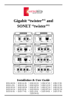
Figure
5
exemplifies the device insertion
and bypass action of the wiring concentrator.
WIRING CONCENTRATOR
\/
%/
ft
I
I
ATTACHING
PRODUCT
|
I
I
I
I
I
I
ATTACHING
PRODUCT
I
1
I
INSERTED
INTO RING
Figure
5.
ATTACHING
PRODUCT
I
|
I
|
I
1
DE INSERTED
FROM RING
Token Ring Wiring Concentrator
[from Ref. 5:p. 1-4]
The LAN cables are terminated at one end with a male 9-
pin subminiature "D" connector and terminated at the other
end
with
a
Medium
Interface
Connector
(MIC)
.
The
"D"
connector attaches to the installed LAN adapter card and the
MIC attaches to the wiring concentrator.
The existing network software
versions of:
includes NCR Corporation
PC Token-Ring System Installation,
17
Token-Ring
Connection Adapter,
installed
these
necessary
software
NETBIOS,
four
program
(except
When
and PC Token-Ring LAN.
DOS)
packages
the
for
provide
all
operation
of
the
a
token-ring LAN.
The PC Token-ring System Installation program is a menu-
driven software package that prompts the user through the
correct installation of the other LAN programs.
Ring
Connection Adapter program provides
software
This
interface.
program
the
package
The TokenLAN
tests
adapter
the
LAN
adapter board to insure that it is functioning properly and
then enables the computer with an installed LAN adapter board
to operate as part of a network.
The NETBIOS (Network Basic
Input/Output System) is a network software interface that runs
on top of the adapter software interface to link LAN adapter
software to the host computer.
The PC Token-Ring LAN is a
menu-driven application program that runs on top of NETBIOS.
This application program allows network users the ability to
perform variety of computer activities including: sending and
receiving
messages,
using
network
disks
and
directories,
utilizing network printers, and displaying the network status.
Installation
and
use
explained in References
B.
of
6
these
programs
are
thoroughly
and 7.
DESCRIPTION OF SIGNAL TO BE MODELED
Interconnection of data processing equipment by way of a
local area network configured in star-wired ring topology and
using a token-passing access method is described by Reference
This standard provided the
3, the ANSI/IEEE 802.5 standard.
baseline for the signal to be modeled.
The signal consists of the following four differential
Manchester encoded symbols:
-
1
binary zero
binary one
J - non-data-J
K - non-data-K
Differential Manchester coding is characterized by two
symbol
Figure
elements per bit with a
forced mid-bit transition.
pictorially describes the differential Manchester
6
coding used within a token ring LAN.
BINARY
ONE
BINARY
ZERO
•1-
BINARY
ONE
BINARY
ONE
BINARY
ZERO
•1'
BINA Y CODE (NRZ)
:
'
DIFFERENTIAL MANCHESTER CODE
Figure
6.
Example of Symbol Encoding
[from Ref.
19
3: p.
74]
The polarities of the line signal element sequence depends
on
polarity
the
of
the
trailing
symbol
previously transmitted data or non-data bit.
element
of
the
If a binary zero
is to be transmitted, the leading symbol element is opposite
of the trailing symbol element of the previous bit and there
forced mid-bit transition.
is a
If a binary one
is to be
the leading symbol element is the same as the
transmitted,
trailing symbol element of the previous bit and there is also
a forced mid-bit transition.
The non-data symbol J has the
same polarity as the trailing symbol element and there is no
mid-bit transition.
The non-data symbol K has the opposite
polarity as the trailing symbol element and again there is no
mid-bit transition.
[Ref.
3:p.
The use of this encoding
73]
process transforms one bit into two baud (two symbol elements
per bit)
A two-baud structure allows the coding of the four
.
symbols: binary one, binary zero, non-data J, and non-data K.
The non-data J and K symbols are used within the token-ring
protocol
frame
for
synchronization.
detection
and
information
format
[Ref. 5:p. 3-6]
exploitation
of
token
and
boundary
This is accomplished by the
missing
mid-bit
transition
within the non-data J and K symbols.
Figure
7
(taken at point
(B)
of Figure
8)
is the signal
to be modeled showing the data and non-data symbols.
wider sequence in the right-center of Figure
non-data J and K symbols.
in Figure
7
7
The
depicts the
The surrounding narrower sequence
depicts the binary one and binary zero symbols.
20
The
data signaling rate is
points
between
(B)
or
(0)
3.0-4.5
,
4
Mbps.
Referring to Figure
8
at
the transmitted signal is required to be
volts
peak-to-peak.
The
changes
voltage
between the 10% and 90% points of the output signal cannot
exceed
25
ns.
[Ref.
3:p.
80]
The
signal
of
conformed to these requirements and was measured at
Figure
4
.
4
7
volts
peak-to-peak with transitions between the 10% and 90% voltage
levels occurring in 22 ns.
Figure
7.
Oscilloscope Display of the Signal to be Modeled
(4.4 volts peak-to-peak)
21
Figure
8.
Schematic of Existing Output Interface Circuit
[from Ref. 5:p. A-lOO]
22
DESIGN DESCRIPTION AND EVALUATION
IV.
A.
DESIGN APPROACH
With the required signal completely characterized,
the
choice of using analog or digital techniques to implement the
design had to be made. The final design was decided by the
available
circuit
components.
The
fiber
optic
receiver
selection was the primary factor in the decision to employ
analog methods.
One available digital fiber optic receiver,
HFBR-2402 by Hewlett Packard,
rates up to
4
5
MBaud.
[Ref.
is capable of supporting data
8:p.
4-31]
The LAN data rate of
Mbps using differential Manchester coding required
8
Mbaud
of coded data, however. This exceeded the capabilities of the
HFBR-2402,
so we required the use of a different receiver.
An available analog fiber optic receiver, HFBR-2404 by Hewlett
Packard, was capable of supporting data rates up to 50 Mbaud
with the appropriate output circuitry and more than adequately
met the data rate requirement. [Ref. 8:p. 4-33]
This resulted
in the decision to use analog data transmission in the fiber
optic link.
The HFBR-2404 receiver has a maximum receive signal pin
voltage of
1
volt.
This produced the requirement to amplify
the electrical output from the optical receiver to the signal
voltage of 3.0-4.5 volts (peak-to-peak) that the LAN requires.
The selection of an operational
23
amplifier to preform this
amplification was based on the need for a fast settling time
and a wide bandwidth.
As mentioned earlier, the LAN signal
is required to transit between the 10% and 90% voltage levels
in less than 25 ns; this was the driving specification in the
op-amp finally chosen.
The EL2020C by Elantec has 1% settling
time of 50 ns but transits between the 10% and 90% voltage
levels typically within 25 ns.
B.
[Ref.
9:pp. 80-82]
THE TRANSMITTER CIRCUIT DESIGN
The transmitter design is built around a direct intensity
modulation scheme.
In this scheme the transmitted signal is
used to directly modulate the light source intensity.
accomplish this,
signal,
DC bias voltage
a
converting
it
from a
To
applied to the LAN
is
bipolar signal
(having
both
positive and negative polarities) to a unipolar signal (having
only a positive polarity)
This conversion is required due
.
to the unipolar nature of light (i.e., light can have varying
intensities but only a single polarity)
.
The response time
of the light source and the time constant of the circuit that
provides the drive current determine the maximum rate
for
direct intensity modulation.
The complete transmitter circuit design is shown in Figure
9
with
component
values
given
in
Table
1.
The
optical
transmitter utilized was the HFBR-1402 by Hewlett Packard.
This transmitter is an LED device, utilized for both analog
and digital designs.
The wiring of the HFBR-1402 (Figure
9)
is
directly
from Reference
experimentally determined.
current
through
with the
8
decreases,
LED
Rl
thereby
If this resistor is too
reducing the optical output power.
large,
of
As the value of Rl increases, the
transmitter
the
exact value
it causes the transmitter LED to operate near cut-off
resulting in a distorted output signal.
resistor
saturate,
is
too
small,
it
causes
However,
this
receiver to
the optical
resulting in a clipped signal. The required value
of Rl was experimentally determined to be 15n.
resulted
if
in
undistorted
an
signal
being
This value
obtained
by
the
optical receiver.
The transmitter circuit performs the two basic functions
of providing a biased signal to the optical transmitter and
providing
impedance
matching
to
the
signal
source.
The
voltage divider network of R4 and R5 is used to supply a prebias drive current to the optical transmitter to obtain a
faster response time from the LED.
The EL2020C is used in
the inverting mode as a voltage summer.
One input of the
summer is the -3 volts supplied by the voltage divider while
the other input is the LAN signal of approximately ±2 volts
(i.e.,
4
volts peak-to-peak).
the biased signal
The output of the summer is
used to directly intensity modulate the
optical transmitter.
The
impedance-matching
provided by R8
to be
2Kn.
.
to
the
LAN
signal
source
is
The value of R8 was experimentally determined
During the initial testing of this design using
25
a signal generator to produce the model of the LAN signal, the
need for this impedance matching resistor was not apparent.
When the final fiber link was inserted into the LAN, however,
the value of this resistor determined whether or not the LAN
functioned properly.
When this resistor is too small,
an
adapter hardware error message from the Token-Ring connection
Adapter program is received and access to the network is
denied.
However, when this resistor is too large, access to
the network menu is granted but communications between the two
computers is not achieved.
Although the exact cause of this
inability to communicate is not known,
the
impedance
process.
specific
mismatch
interferes
it is theorized that
with
the
ring
polling
This process enables the computer to acquire the
address
of
its
upstream
neighbor.
Since
these
computers are the upstream neighbors of each other, without
an upstream neighbor address they do not recognize each other
as network stations and, therefore, cannot communicate.
INPUT SIGNAL.
Wy
1
I
VA
1
r
NOTE
1:
NOTE
2:
All op-amp power supplies are capacitively coupled
to ground by 4.7uF tantalum capacitors.
All capacitor values are in microfarads.
Figure
9.
Transmitter Circuit Schematic
26
TABLE 1
OPTICAL TRANSMITTER CIRCUIT COMPONENT VALUES
R5 = IK
Rl = 15
R2 = IK
R6 = IK
R3 = 330
R7 = IK
R4 = 430
R8 = 2K
THE RECEIVER CIRCUIT DESIGN
C.
The
receiver
design
(Figure
10)
accepts
incoming
the
modulated light signal, converts it to an electrical signal,
and amplifies the electrical signal through a series of stages
to recreate the LAN signal.
The complete receiver circuit design is shown in Figure
with
10
component
values
given
in
Table
2.
As
stated
previously, the optical receiver utilized was the HFBR-2404
by Hewlett Packard.
and
produces
an
This receiver contains a PIN photo-diode
inverted
received optical signal.
of the HFBR-2404
analog
voltage
replica
of
the
Although the actual internal wiring
is not explicitly supplied in Reference 8,
connecting the device is straightforward.
The
amplification
stages
of
the
receiver
mathematically determined and experimentally optimized.
were
The
gain was accomplished in stages to maintain a wide bandwidth.
Not doing so would result in severe signal distortion.
a
For
given gain, the bandwidth can be increased by decreasing the
feedback resistor, but reducing the feedback resistor results
27
in
excessive
oscillations.
overshoot,
ringing,
and
(eventually)
Four stages were experimentally determined to
balance this gain/bandwidth tradeoff.
The gain of each stage,
listed in order from the detector, are: inverting gain of
inverting gain of 10,
gain of
1.
inverting gain of 1.5,
2,
and inverting
The last stage corrects the polarity of the output
signal to match the original signal from the transmitter.
OUTPUT SIGNAL
All op-amp power supplies are capacitively coupled to
ground by 4.7uF tantalum capacitors.
NOTE 2: All capacitor values are in microfarads.
NOTE
1:
Figure 10.
Receiver Circuit Schematic
TABLE 2
RECEIVER CIRCUIT COMPONENT VALUES OPTICAL
Rl = 510
R6 = IK
R2 = 330
R7 = 430
R3 = 330
R8 = 680
R4 = 680
R9 = 750
R5 = 100
RIO = 750
DESIGN EVALUATION
D.
The design evaluation started with the requirement to pass
the modeled LAN signal over the fiber optic link and correctly
recover the signal at the distant end.
The LAN signal was
modeled as a square wave with frequencies varying from
4
MHz using a signal generator.
to the optical transmitter circuit of Figure
at the
1
to
These signals were applied
9
and measured
The
output of the receiver circuit of Figure 10.
varying frequencies account for the dissimilar number of level
transitions between a series of data zeros, a series of data
ones, and the non-data J-K sequence.
The received signals at
1
MHz,
2
MHz,
4
MHz,
are shown in Figures 11 though 14 respectively.
seen
in
the
2
MHz and
4
and
7
MHz
The ripples
MHz signals of Figures 12 and 13
respectively were produced at the transmitter by the signal
generator.
Note that in Figure 14 the
7
MHz received signal
no longer resembles the input square wave and so provides an
upper signal rate bound.
Referring to Figure 15, the design
criteria of a transit time of less than
25
10% and 90% voltage levels is depicted.
ns
between the
This demonstrates
the modeled received signal meets the transit time design
criteria.
f^
f^^
^^W
Figure 11.
1
^fP
f^
^Wi
f^
^Pp
iPUp
Oscilloscope Display of Received Signal at
MHz 3.8 volts and peak-to-peak
/"
f
V/
\n
Figure 12.
2
Figure 13.
Oscilloscope Display of Received Signal at
MHz and 4 2 volts peak-to-peak
.
Oscilloscope Display of Received Signal at
MHz and 3.8 volts peak-to-peak
4
Figure 14
Oscilloscope Display of Received Signal at
and 3.8 volts peak-to-peak
Figure 15.
Oscilloscope Display of Received Signal at 4 MHz
Showing a 24.30 ns Transit Time Between the 10%
and 90% Voltage Levels as marked by the cursors.
7
MHz
To further evaluate the design,
fiber optic
a duplicate
link was constructed for experimental insertion into the LAN.
Referring to Figure 16, the input signals to the fiber optic
links are the LAN signals from the wiring concentrator; the
output signals are fed to the receive pair on the LAN adapter
card.
Figure 17 shows the input LAN signal to the fiber optic
link.
Figure 18 shows the corresponding LAN signal at the
distant
end
the
of
optic
fiber
successful
after
link
transmission through the link.
1
1
Computer
'
1
Configured
1
XMTl '^
XMT2 I^
^1 RCVl
^« RCV2
as
^TxMTl
^1
1
2
"firing
^'^^'
1
i
Computer
!
Concentrator
USER
—
'
'^'\rn\"n'\nr\'.
RCV2 i_
r^,
1
1
1
1
^
1
E/o|_Q_|o/E
^
^'^
1
Configured
!
l-I-^
as SER
Fiber Optic
Link
Figure 16.
Local Area Network System Block Diagram
with Inserted Fiber Optic Link
33
VER
^n'.M<^*.w,
t^uh
\h
Figure 17.
Oscilloscope Display of LAN Signal of the
Input to the Transmitter circuit
4 volts peak-to-peak
Hi Ml
*
Figure 18.
^'<^ ^*
«^
H
I
ill
I
11^,
nH
iH M
»^
L
.
^y
*
k
w
•"
Oscilloscope Display of LAN Signal at the
Output of the Receiver Circuit
4 2 volts peak-to-peak
.
The
final
transparency.
I
evaluation of the design was a question of
A transparent insertion as defined in Chapter
conforms to the following criteria:
developed for
o
meet existing standards of Reference
dual twisted-pair copper wire,
o
not adversely affect the software protocol, and
o
allow the LAN to communicate over the fiber optic link.
3
Using the NCR network software, messages were passed from one
computer to the other over the design link and were accurately
received.
NCR network software allows the direct use of a network
computer's hard disk drive by another computer on the network.
This feature was also used to evaluate the design link.
Using
the LAN computer without the fiber optic link (the User)
,
a
file was created and saved on hard drive of the LAN computer
with the fiber optic link (the Server)
.
This same file was
then repeatedly recalled by the user computer, modified, and
saved back on the server computer's hard drive with complete
accuracy.
Although not exhaustive,
the evaluation of this design
supplies documentation of all original objectives as stated
in Chapter I.
CONCLUSIONS AND RECOMMENDATIONS
V.
CONCLUSIONS
A.
This thesis accomplished the design goal
fiber optic link for a token-ring LAN.
of producing
The ultimate test of
this link would be to utilize it in both the transmit and
receive signal pairs.
This is not possible due to the AC
nature of the optical receiver circuit and its inability to
pass the DC voltage provided by the phantom drive.
that
phantom
drive
activates
the
relays
of
concentrator to insert the station into the ring.)
fiber optic LAN,
the
(Recall
the
wiring
Within a
insertion is accomplished by control
information carried by special MAC frames.
[Ref.
l:p.
240]
RECOMMENDATIONS
B.
The following list provides follow-on research topics in
this area and includes both hardware and software issues.
o
Modify/write the software to allow insertion
into the ring via MAC frames.
o
Replace the wiring concentrator with optical
fiber star coupler.
o
Multiplex the transmit pair and receive pair
to reduce the cable requirement from 4 to 2
optical fibers.
REFERENCES
Bux,
and
Werner, "Token-Ring Local-Area Networks
Their Performance," Proceedings of the
77, No. 2, pp. 238-255, 1989.
IEEE, Vol.
Greenfield, David, "Chasing the Light Fiber
Optic LANS for Today and Tomorrow," LAN
Magazine, pp. 63-78, August 1989.
ANSI/IEEE Standard 802.5, Token Ring Access
Method and Physical Layer Specifications
IEEE, Incorporated, 1985.
,
Keiser, Gerd E., Local Area Networks
Hill, Inc., 1989.
.
McGraw-
Texas Instruments Incorporated, TMS3 80 Adapter
Chipset User's Guide 1985.
,
NCR Corporation, NCR PC Token-Ring System NCR
PC LAN Program User's Manual
Dayton, Ohio,
.
1987.
NCR Corporation, NCR PC Token-Ring System NCR
PC LAN Program Administration Manual
Dayton,
.
Ohio,
1987.
Hewlett-Packard
Designer Catalog
.
Opto-Electronics
Company,
1986.
Palo Alto, CA.
,
Elantec, Inc., Elantec High Performance Analog
Integrated Circuits Data Book Milpitas, CA.
.
1988.
37
INITIAL DISTRIBUTION LIST
No. Copies
1.
Library, Code 1424
Naval Postgraduate School
Monterey, California 93943-5000
2.
Chairman, Code 62
Department of Electrical and
Computer Engineering
Naval Postgraduate School
Monterey, California 93943-5000
3.
Prof. John P. Powers, Code 62Po
Department of Electrical and
Computer Engineering
Naval Postgraduate School
Monterey, California 93943-5002
4.
Curricular Officer, Code 32
Naval Postgraduate School
Monterey, California 93943-5000
5.
Prof. Tri T. Ha, Code 62Ha)
Naval Postgraduate School
Monterey, California 93943-5000
6.
Defense Communication Agency
ATTN:
LT M. L. Anderson (Code B-541)
Washington, DC 20305-2000
7
Commander
Space and Naval Warfare Command
ATTN:
Mr. M. Potosky, PDW-180
Washington, DC 20370-5000
8.
Defense Technical Information Center
Cameron Station
Alexandria, Virginia 22304-6145
38
Thesis
A4585
c.l
Anderson
Design and implementation of a token-ring fiber
optic local area network
interface module.
(4^