
1
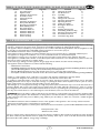
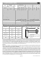
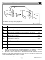
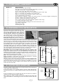
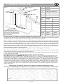
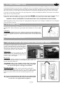
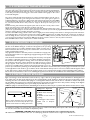
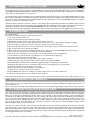
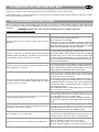
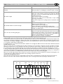
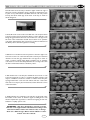
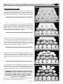
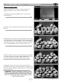
INSTALLATION & USER INSTRUCTIONS
POWERFLUE GAS FIRE RANGE
MODELS COVERED BY THESE INSTRUCTIONS
Focal Point Fires plc.
Christchurch, Dorset BH23 2BT
Tel: 01202 499330
Fax: 01202 499326
www.focalpointfires.co.uk
e : [email protected]
FINSBURY SLIMLINE CONVECTOR POWERFLUE FINSBURY FULL DEPTH POWERFLUE ARCH SLIMLINE CONVECTOR POWERFLUE ARCH FULL DEPTH POWERFLUE AURA SLIMLINE CONVECTOR POWERFLUE AURA FULL DEPTH POWERFLUE BLENHEIM SLIMLINE CONVECTOR POWERFLUE BLENHEIM FULL DEPTH POWERFLUE LULWORTH SLIMLINE CONVECTOR POWERFLUE LULWORTH FULL DEPTH POWERFLUE -
GB IE
F500283
F500284
F500285
F500286
F500287
F500288
F500289
F500290
F500291
F500292
BS EN 13278 : 2003
KM579168
‘Aura’ firefront
‘Finsbury’ firefront
‘Arch’ firefront
‘Blenheim’ firefront
‘Lulworth’ firefront
IN THE UK ALWAYS USE A GAS SAFE REGISTERED ENGINEER TO INSTALL, REPAIR OR SERVICE THIS APPLIANCE
Please note : Except where otherwise stated, all rights, including
copyright in the text, images and layout of this booklet is owned
All instructions must be handed to the user for
by Focal Point Fires plc. You are not permitted to copy or adapt
safekeeping.
any of the content without the prior written permission of Focal
Revision B 11/11
Point Fires plc.
© 2011 Focal Point Fires plc.
1
I N S TA L L AT I O N
Section
1.0
2.0
3.0
4.0
5.0
6.0
7.0
7.1
8.0
8.1
8.2
8.3
8.4
8.5
8.6
8.7
Contents
Important Notes
Appliance Data
Installation Requirements
Terminal Location
Site Requirements
Ventilation
Unpacking the Appliance
Component Checklist
Preparing for Installation
Outer Wall Aperture
Gas Supply Routes
Installation Method 1
Installation Method 2
Installation Method 3
Flue Preparation
Firebox and Tray
Page No.
2
3
3
4
5
5
5
6
6
6
7
7
8
9
10
10
I N S T R U C T I O N S
Section
8.8
8.9
8.10
9.0
10.0
11.0
12.0
13.0
14.0
15.0
15.1
15.2
15.3
15.4
16.0
1.0 IMPORTANT NOTES
Page No.
Contents
10
Fitting Fan Terminal
11
Gas Connection
11
Spark Gap
11
Fuel Bed Layout
11
Fitting Frame and Front
12
Operating the Appliance
12
Operating Pressure
12
Testing for Spillage
13
Briefing the Customer
13
Servicing
13
Cleaning the Ceramics
13
Dismantling the Burner Tray
14
Checking the Fan Assembly
15
Control Box Removal
15
Troubleshooting Guide
GB IE
• This appliance is an Inset Live Fuel Effect appliance which provides radiant warmth utilising the latest type burner technology.
• The fire is designed to suit various types of fireplaces and installation methods as detailed in this manual.
• The appliance must be installed by a competent person in accordance with Gas Safety (Installation and Use) Regulations 1998.
It is strongly recommended that a GAS SAFE registered engineer be used for this purpose.
• Read all these instructions before commencing installation.
• This appliance must be installed in accordance with the rules in force and used only in a sufficiently ventilated space.
• The appliance is designed for installation on to a non-combustible hearth of at least 300mm depth.
• This appliance is factory set for operation on the gas type, and at the pressure stated on the appliance data plate.
• This appliance is available with a number of fuel effect options. These instructions cover all fuel effect options. See the relevant sections of these instructions for further details.
• In the event of gas leakage from the appliance, the gas supply must be turned off at the nearest isolating valve.
• The appliance must be installed in accordance with the following:
• Manufacturers' Instructions.
• The Building Regulations issued by the Department for Communities and Local Government, the Building Standards (Scotland)
(Consolidation) Regulations issued by the Scottish Development Department.
• Relevant British Standards insofar as the relevant areas are not covered by these instructions.
• For Republic of Ireland, reference should be made to the current edition of IS813 (the relevant standards governing installation).
• Failure to comply with the above could lead to prosecution and deem the manufacturer’s warranty invalid.
• The appliance is designed to fit various types of situations as described in sections 8.3 to 8.5.
• It should be noted that heaters create warm air currents. These currents move heat to wall surfaces next to the heater.
Installing the heater next to vinyl or cloth wall coverings or operating the heater where impurities in the air (such as tobacco
smoke, candle smoke etc.) exist, may cause the walls to become discoloured.
• On first light up of a new appliance, burning off of high temperature paint and lubricants may occur for the first few hours of
operation. During this period some smoke may be emitted from the outlet grille, this should be no cause for concern.
Accordingly, the room should be well ventilated with all windows and doors open during this period. During this period the appliance may cause smoke alarms to sound. If this happens, reset the alarms, but do not remove the batteries.
• WARNING: Due to the nature of this product the area around the top of the appliance gets very hot. Care should be taken
when operating the appliance. The manufacturer of this appliance considers all surfaces as working surfaces with the exception
of the control knob and ash pan door. Where young children, pets, the elderly or infirm are concerned, a suitable fireguard
should be used.
• Consult ALL instructions before installation and use of this appliance. This appliance is free from any asbestos material.
• Refractories and fuel bed are constructed from ceramic fibre.
• The efficiency of the appliances covered by these instructions has been measured as specified in BS 13278:2003 and the results
are;
Full depth models : 53%
Slimline models : 52.5%
The gross calorific value of the fuel has been used for this efficiency calculation. The test data from which it has been calculated
has been certified by GL Industrial Services (0087). The efficiency value may be used in the UK Government’s Standard
Assessment Procedure (SAP) for energy rating of dwellings.
2
© 2011 Focal Point Fires plc.
2.0 APPLIANCE DATA
Model
Destination
Country
Natural gas
Full Depth
Slimline
GB - IE
GB - IE
Specifications
Main burner injector
Oxypilot (Natural Gas Models)
Gas Control (All Models)
Gas Inlet
Ignition
Spark Gap (± 1.0mm)
Electrical supply
Power consumption
Fuse rating
Approximate weight
Flue specification
Efficiency
Efficiency class
Cat
I2H
I2H
GB IE
Inlet/Operating
Pressure (±2.0 mbar)
Max Energy Input (kW)
Min Energy Input (kW)
G20
G25
G30
G31
Gross
Net
Gross
20
-
-
-
6.2
5.6
3.5
20
-
-
-
6.8
6.1
3.5
Net
3.15
3.15
Full Depth Models
Slimline Models
Stereo size 79
Stereo size 78
SIT 9081
SIT 9090
Copreci 21400 Series
Copreci 21400 Series
8mm Inlet restrictor elbow
8mm Inlet restrictor elbow
Piezo Spark
Piezo Spark
4.0mm
4.0mm
230 V AC, 50 Hz
230 V AC, 50 Hz
0.3A Running, 0.4A Start-up
0.3A Running, 0.4A Start-up
3A
3A
Fire unit 20KG, Fan unit 12KG
Fire unit 20KG, Fan unit 12KG
Twin wall circular provided as part of appliance. No additional or alternative flue
may be used. Outer flue tube diameter 120mm.
53% Gross, 58.8% Net
52.5% Gross, 58.3% Net
2
2
3.0 INSTALLATION REQUIREMENTS
Dimension
Full Depth Models
Slimline Models
‘A’
205mm
150mm
‘B’
170mm
125mm
‘C’ Minimum
100mm
100mm
‘C’ Maximum
600mm
600mm
‘D’
90mm
90mm
Figure 1
B
A
C
D
A = Firebox fitting depth (inc. 25mm for
Rockwool jacket
B = Depth from rear of firebox frame to spigot
C = Flue pipe length
D = Permitted recess depth of terminal box
(Optional).
Internal
This appliance MUST NOT be installed into a room containing a bath or shower, or where steam may be present. It is not recommended that the appliance be installed in areas where it is likely to be directly exposed to persistent strong draughts, that may be generated by outside doors, windows, air vents, air conditioning units, extractor fans, ceiling fans etc. See section 4.1 for more information on ventilation. The firebox must be installed onto a suitable non-combustible insulating surface at least 12mm thick, covering the entire base area of the box.
This appliance is suitable for use with a “lightweight” surround and back panel of 150ºC minimum rating. A suitable gas supply and an
electrical 3 Amp fixed fused spur are both required near the intended appliance site.
External
Please refer to the diagram on the following page for more details of the most suitable site for the fan terminal. The terminal must be
located so that the outlet is not obstructed in any way allowing poor disposal of combustion products. A safety cage should be fitted in
place over the terminal to ensure compliance with Byelaws.
Terminals located in passageways between two properties, public footpaths or which might discharge over the same may be subject to
local Byelaws on items such as minimum distances for projection. In these circumstances it is the installers responsibility to check that
the location of the terminal does not infringe any Byelaws. If in any doubt about flue terminal location, especially with regards to garages
and car ports then further advice should be sought from GAS SAFE or the manufacturer. Avoid locating the terminal in close proximity to combustible materials, such as plastic drainpipes and fences. If these are impossible to avoid, then a suitable metal deflector must
be used if the flue gasses begin to heat the object. For minimum standard dimensions of clearance see section 4.0. Covered areas such
as under car ports should be avoided but if no alternative is available the following notes should be adhered to; The covered area should
have at least two open sides (i.e. a roof and ONE supporting wall). If more than one side is filled, then advice must be sought on the
location’s suitability. Any openings into dwellings such as doors, windows and air vents under the covered area must be at least 1200mm
away from the terminal position. If the roof is constructed from plastic material, great care must be taken with the installation as there
is no simple method of protecting this type of roof from heat build up.
3
© 2011 Focal Point Fires plc.
4.0 TERMINAL LOCATION
GB IE
Figure 2
Note : A suitable metal protector may be required where temperature sensitive building components e.g. plastic pipes are
concerned
Minimum clearances are as follows;
Symbol
Location
Ba)
Above an opening, air brick, opening window etc.
Aa)
Ca)
D
E
F
G
Hb)
I
J
K
L
M
N
Notes:
a)
b)
Dimension
Directly below an opening, air brick, opening windows etc.
Horizontally to an opening, air brick, opening window etc.
300mm
300mm
Below temperature sensitive building components e.g. plastic gutters, soil or drain pipes
300mm
75mm
Below eaves
200mm
From a vertical soil or drain pipe
150mm
Below balconies or car port roof
200mm
From an internal or external corner
200mm
Above ground, roof or balcony level
300mm
From a surface facing a terminal
600mm
From a terminal facing a terminal
1200mm
Vertically from a terminal on the same wall
1500mm
From an opening in the car port (e.g. door window) into the dwelling
Horizontally from a terminal on the same wall
1200mm
300mm
In addition, for temperature and structural reasons the terminal should not be closer than 150mm to an opening in the
building fabric formed for the purpose of accommodating a built-in element such as a window frame.
The reference to external corners does not apply to building protrusions not exceeding 450mm, such as disused chimneys on external walls.
Care should also be taken with the terminal location relative to nearby plants, grass, or trees as the gasses expelled may be hot
enough to damage them. At least 1000mm clearance is recommended.
Note : Dimensions relate specifically to the exhaust outlet at the base of fan terminal box.
4
© 2011 Focal Point Fires plc.
5.0 SITE REQUIREMENTS
GB IE
For aesthetic purposes it is essential that the hearth and infill plinth area are flat and level.The hearth and infill must also be square
to the back panel. Failure to comply with this could cause the appliance to lean away from the fireplace resulting in an unsatisfactory installation.
The electrical earth to the property and all wiring must be carried out in accordance with IEE Wiring Regulations (including any
Local Regulations). If you are unsure about this aspect, then professional advice should be sought. This appliance is suitable for use
with a 230V~50Hz (AC) single phase (normal domestic) electrical supply. Connection to the mains supply should be made with
the three core cable (green/yellow -earth, blue - neutral, brown - live) to a fixed fused spur with double pole insulation (minimum
3mm separation of poles) and fused at 3 amp. Take care not to pull or damage the internal wiring to the the fan unit at any time
during installation. Should the mains cable become damaged at any stage, it should only be replaced with the manufacturers supplied cable (part no. F930137). Failure to use a genuine spare could cause a hazard.
WARNING! THIS APPLIANCE MUST BE EARTHED.
If a concealed gas supply is to be used, the supply pipe must be sleeved through walls and floors. If the fire is to be inset into the
cavity leaf, only factory sleeved pipe should be used. For further details see relevant section. A separate isolation device must be
incorporated into the incoming gas supply to facilitate servicing. No more than 1.5 metres of 8mm pipe should be used in the
connection of the gas supply to the appliance, as more could result in an unacceptable drop in pressure.
This appliance must only be installed onto a non-combustible wall or surface. The fire requires a hearth with a non-combustible
surface at least 12mm thick. The top surface of the hearth must be at least 50mm above floor level, or be surrounded by a raised
edge or fixed fender of at least 50mm high.The non-combustible hearth must extend a minimum of 300mm in front of, and 150mm
either side of the live part of the appliance. The hearth must therefore be a minimum of 680mm wide.
The appliance must be installed by one of the following methods;
1 - Fitment against an existing inner house wall with a suitably constructed fireplace and/or false chimney breast to enclose
the depth of the fire.
2 - Insertion into a purpose made opening in the inner leaf of a cavity wall or disused fireplace opening with the use of a suitable fireplace surround etc. Note: The appliance must not bridge the cavity - any overhang being kept to a minimum,
and the Installation instructions must be adhered to. Building Control requirements may vary in some areas, enquiries
should be made accordingly.
3 - Installation into a timber framed dwelling using the clearances to combustible materials shown in the relevant section.
Building Control requirements vary in some areas, enquiries should be made accordingly.
An unprotected combustible shelf may be fitted above the appliance, provided it complies with the minimum dimensions stated
below. Protective materials can be used to deflect heat from shelves that are too low.
Maximum depth of shelf
Minimum distance from finished hearth
surface to underside of shelf
745mm
845mm
895mm
100mm
150mm
203mm
A non-combustible shelf may be fitted to within 10mm of the top edge of the fireframe. Combustible materials, such as wood,
may be fitted to within 100mm of either side of the frame of the firebox providing it projects no further forward than 100mm.
As with all heating appliances, decorations, soft furnishings and wall coverings (such as blown vinyl, flock and embossed paper)
may discolour or scorch if positioned too close to the fire. If the appliance is fitted to a dry-lined wall, the gap between the plasterboard and blocks must be sealed with non-combustible material and any unplastered board replaced with superlux or other
non-combustible material if in direct contact with the appliance.
6.0 VENTILATION
No purpose provided ventilation is normally required with this appliance. However, the ventilation requirements of other gas
appliances in the same room or space should be taken into consideration. A spillage test should be carried out as described in
the relevant section with the doors and windows both open and closed, and with any extractor fan running on full. Where fitted,
ventilation must comply with the requirements of BS 5440 part 2. Vents directly underneath or within the immediate vicinity of
appliances must not be used as they may adversely affect ODS pilot operation.
Note: For Republic of Ireland see IS813, ICP3 and IS327 and any other rules in force.
7.0 UNPACKING THE APPLIANCE
Stand the carton right way up, cut the strapping bands and remove the top end cap.
Read all the instructions before continuing to unpack or install this appliance. Remove the box containing the fire front, and the
bag containing the ceramics.
Remove the cardboard packing pieces, and any bags containing other fittings or parts. When all loose parts have been removed,
the outer sleeve may be lifted off to reveal the appliance. Check that the components supplied correlate with the checklist given
in section 7.1. Please dispose of the packaging materials at your local recycling centre.
5
© 2011 Focal Point Fires plc.
7.1 COMPONENT CHECKLIST
QUANTITY
1
1
1
1
1
1
1
1
1
3
1
1
2
1
1
1
1
GB IE
DESCRIPTION
Firebox and burner tray assembly
Decorative front and frame assembly (depending on model)
Moulded ceramic fibre combustion matrix
Front ceramic strip (full depth versions only)
Bag of 16 moulded ceramic coals or pebbles (full depth models only)
Bag of 11 moulded coals (Slimline coal models only)
Bag of 15 moulded pebbles (Slimline pebble models only)
Set of manufacturers instructions
Bag of fixings (10 wallplugs, 10 No.8 x 40 screws, 4 No.8 x 0.5 screws), 3 lengths of sealing strip
Ceramic radiant panels (full depth models only)
Ceramic radiant panel (slimline models only)
Pair of small ceramic side cheeks (Slimline pebble models only)
‘L’ brackets (full depth models only)
Fan terminal assembly including fan box trim and fan box cover
Twin-walled tubular flue
Mineral wool jacket
Terminal guard cage
8.0 PREPARING FOR INSTALLATION
Remove the fire tray from the firebox by removing the two securing screws in the front legs of the
tray and rear mounted transit screws, and invert
the tray. Carefully unplug the safety solenoid on
the tray from the control box by squeezing the
clip on the three way connector and easing apart.
Place the tray safely to one side along with the fuel
bed components, firefront and decorative frame.
Figure 4
Full depth models only : The three radiant panels may now be fitted inside the firebox. Select the plain or patterned side of the
panels and insert as follows; Lay the firebox on it’s back. Lay the tapered panel
onto the rear face of the firebox. The side panels should be fitted by inserting
their front edges into the pre-fitted retaining brackets on the front face of the
firebox. Gently align the side panels with the sides of the firebox, over the back
panel already in place as shown in figure 3. Make sure that the side panels are
pushed up firmly to the roof of the firebox, and back firmly to retain the rear
panel. Make small adjustments to line up the mortar lines if required. Clamp the
side panel using the ‘L’ shaped brackets and screws provided as shown in figure 4.
The screws should locate into the holes in the sides of the firebox.
All models : Apply the self adhesive sealing strip to the rear perimeter of the
firebox frame so as not to be visible. This will eventually seal the firebox to the
fireplace back panel. Place the fire to one side whilst the site is prepared for flue
installation. As shown in figure 5, mark the vertical centreline of the desired location of the appliance after first checking for clearances to pipes and cables in the
wall, and also the terminal position outside.
Note : The vertical centreline of the pilot hole will be 500mm from the floor
PLUS the thickness of the hearth you are using. This dimension is obviously
FROM the hearth top surface if it is already fitted
Mark the position of the 30mm cable hole in relation to the flue centreline. Using
a suitably long masonry bit, drill through both leaves of the cavity wall. Check outside that the clearances from the hole are adequate for installation to proceed.
Check all dimensions with the diagram in the relevant section. Now drill the
30mm cable hole in the wall.
8.1 OUTER WALL APERTURE
From the outside of the property, open up the pilot hole in the external leaf
of the cavity to the required size.
If the fan terminal is to be mounted directly onto the outside wall, the hole
should be opened up to a 125mm diameter aperture centred around the pilot
hole.
If the fan terminal is to be recessed into the outer leaf, the hole should be
opened up to the dimensions given in figure 6.
Clear all the brick rubble and debris that may have fallen into the cavity. If the
cavity wall insulation is obstructing your view of the inner leaf then clear this
back.
6
Figure 3
Proposed location of appliance
120mm
500mm
PLUS
thickness of
hearth
Cable
routing
hole
Centreline of flue
Figure 5
Figure 6
297mm307mm
105mm
118mm
139mm
Pilot
hole
192mm
257mm-267mm
© 2011 Focal Point Fires plc.
8.2 GAS SUPPLY ROUTES
GB IE
The gas supply may enter the appliance across the hearth or through the ‘knock outs’ provided in the rear of the firebox. Gas
pipes should not be buried or routed through walls without being protected by conduit or sleeving. An isolation tap must be
included in the gas connection pipe to facilitate servicing.
Figure 7
Note: Any fittings used underneath the appliance must be
Outer leaf
rated to 80 C and must not come into contact with the
underside of the burner unit
o
Cavity
For INSTALLATION METHOD 1, the gas supply can be run in the
conventional manner taking due account of rules and regulations.
For INSTALLATION METHOD 2, use only factory sleeved pipe in a
continuous unjoined length in the cavity of the wall and area which
communicates with the cavity. Ensure a good seal where the pipe
enters through the appliance grommet. This is a permitted gas supply routing.
Firebox
8.3 INSTALLATION METHOD 1
Figure 8
Fireplace
backpanel
Outer cavity leaf
Rockwool
Insulation
E
D
C
Inner cavity leaf
A
A
Opening width
C
Overall height (excluding hearth)
B
D
E
F
Model
Dim.
F
A Min.
A Max.
B
B
C
D Min.
The hearth must extend 300mm
in front of the appliance, with it’s top surface 50mm above the surrounding floor
level or having a 50mm high fixed fender
around it’s perimeter.
False chimney
breast
Fireplace panel
D Max.
E
F
Overall width
Opening height: (excluding hearth):
Recessed depth of fire
Space allowed for Rockwool jacket:
Full depth
models
Slimline models
460mm
450mm
375mm
380mm
480mm
480mm
590mm
565mm
580mm
180mm
25mm
590mm
540mm
580mm
125mm
25mm
This method requires minimal modification to the property’s wall and is achieved utilising either an extended
fire surround or by constructing a shallow false chimney breast of a minimum 180mm deep. See diagram for further dimensions.
Centring on the pilot hole already drilled, create a hole from inside the property 125mm diameter. If the property has loose fill
cavity wall insulation fitted, it will be necessary to seal the wall cavity where the flue opening is formed to prevent insulation material coming into contact with hot surfaces of the fire and it’s components. The recommended method is to pack a depth of 50100mm of Rockwool or a similar non-combustible insulation material into the cavity .
Where the property does not have existing cavity wall insulation, it is still recommended that a space 50-100mm into the cavity
is packed with Rockwool or similar material, to prevent any future installation of cavity wall insulation from coming into contact
with hot areas of the appliance.
At this point the false chimney breast or fire surround should be installed.
Note: When constructing the stud partition, all uninsulated, combustible material must be kept a minimum of
75mm away from the fireplace. Combustible materials closer than 75mm MUST be protected with a minimum
of 25mm insulation material.
7
© 2011 Focal Point Fires plc.
8.4 INSTALLATION METHOD 2
Figure 9
Outer cavity leaf
Fireplace
backpanel
GB IE
Superlux
board
Lintel
E
D C
A
Opening width
C
Overall height (excluding hearth)
B
D
Inner
cavity
leaf
E
Model
Dim.
A Min.
A
A Max.
B
B
C
D Min.
The hearth must extend 300mm
in front of the appliance, with it’s top surface 50mm above the surrounding floor
level or having a 50mm high fixed fender
around it’s perimeter.
D Max.
E
Overall width
Opening height: (excluding hearth):
Recessed depth of fire
Full depth
models
Slimline models
460mm
450mm
375mm
380mm
480mm
480mm
590mm
565mm
580mm
180mm
590mm
540mm
580mm
125mm
This method allows for installation of the appliance with the rear part of it's firebox
recessed into the inner leaf of the cavity wall. This will enable a standard fireplace to be flush fitted to the wall and the appliance
will then be fitted flush into the fireplace. The structural integrity of the wall must be maintained.
Check on the type of cavity insulation used, and if it is of the granular type then take suitable precautions when opening up the
wall not to allow excessive loss of insulation material from the cavity. Packing the cavity with Rockwool should help hold back
loose fill insulation material. Unless lime and mortar has been used, it will be necessary to drill four holes with a masonry, drill,
and then use a mechanical cutter (Sharksaw) to cut out the correct size of 'slot' required for the chosen lintel. Obtain a lintel
750mm long x 75mm deep x thickness of the inner leaf. We would suggest either a pre-cast concrete or steel lintel; Catnic
CN52 or CN46 depending on thickness. Typical inner leaf weights when sizing a lintel over a 450mm wide opening are 90kg for
100mm blockwork and 120kg for 125mm blockwork.
Plan to minimise disruption to occupants and protect any other parts of the building against dust infiltration.
Areas that are opened up will need to be protected against rain or snow during the work and if there is a risk of frost, replacement brickwork will require protection until mortars have hardened.
Set out where possible centrally beneath a block join as shown. Use a drill for guide holes, and a 'Sharksaw' or angle grinder to
form an opening to suit the lintel.
The lintel should be inserted and securely slate pinned, leaving the wall above safe and firm.
Note: Always bed on mortar, DO NOT dry bed. Remove all masonry from below the lintel, and clear debris from the
cavity. The top of the exposed cavity must be sealed with Superlux board or a similar non-combustible material. The board
should be fixed at an angle, lower at the back, so as to direct any moisture coming down to the outside wall. This board should
be fixed with screws, Unibond, or a similar adhesive. It is important to fit this board or a cavity tray to protect the property
and the appliance from drips of water. The sides of the opening where the cavity is exposed should be packed with Rockwool
or similar non-combustible material to a minimum depth of 50mm. The Rockwool packing must extend from the base of the
opening to the Superlux board. The non-combustible hearth should now be formed or secured in place.It is essential the mineral wool jacket be fitted to the rear of the appliance to prevent condensation and to insulate the appliance firebox from the
cold air of the cavity.
Note: Neither the appliance firebox nor the mineral wool jacket should bridge the cavity.
Consult your local Building Control Department for any additional construction requirements or further advice.
Figure 10
8
© 2011 Focal Point Fires plc.
8.5 INSTALLATION METHOD 3
Figure 11
GB IE
A
Opening width
C
Overall height (excluding hearth)
B
Fireplace
backpanel
Superlux
board
E
D
E
Model
D C
Dim.
A Min.
A Max.
A
B
B
C
D Min.
The hearth must extend
300mm in front of the appliance,
with it’s top surface 50mm above the
surrounding floor level or having a 50mm
high fixed fender around it’s perimeter.
D Max.
E
Installation into timber framed dwellings
Overall width
Opening height: (excluding hearth):
Recessed depth of fire
Full depth
models
Slimline models
460mm
450mm
375mm
380mm
480mm
480mm
590mm
565mm
580mm
180mm
590mm
540mm
580mm
125mm
Where removal of any part of the inner timber leaf of the wall is involved, the structural integrity of the wall must be maintained
and the advice of your local Building Control Department should be sought. If the property is under any N.H.B.C. cover, it is
advised that their advice on this modification should also be sought.
Either of the two preceding methods of installation may be adapted for use in timber framed buildings, providing extra care is
taken to prevent combustible materials from contact with hot surfaces.
The appliance must be installed in accordance with British Gas documents DM2 and DM3 or the Institute of Gas Engineers
published procedure IGE/UP/7. Special attention must be paid to the location of the studwork frames of the inner leaf and the
appliance positioned accordingly. Wires and pipes that run within the inner timber leaf must also be located and taken into
account when positioning the appliance.
Installation using rebated fire surround or false chimney breast.
When using this method of installation the following amendments should be incorporated; 25mm clearance must be allowed from
the appliance firebox to any insulated combustibles.
75mm clearance must be allowed to any unprotected combustibles. 50mm minimum thickness of insulation should be provided
around flue pipe and gather hood. Where the flue pipe passes through the inner leaf, a hole 100mm larger than the flue should
be cut to allow 50mm air gap around the entire flue circumference.
The vapour barrier on the back of the inner leaf should be cut and carefully fixed to prevent any ingress of damp into the plasterboard layer. A layer of insulation will need to be provided to insulate the surface of the inner wall from the heat effect of the
flue. It may be advantageous to use a sheet of Superlux board for this purpose.
Installation by setting the appliance into the inner leaf of wall.
When setting the appliance into the inner wall find a suitable position between the wall panel frames and carefully open up a hole
to the dimensions given in the relevant section, paying careful attention to securing the damp proof membrane back into position. A drip collar of galvanised or stainless steel should be formed with the twisted joint on the underside of the flue to disperse
drips - see figure 12.
An air gap of 75mm between all hot surfaces and the surrounding wall
should be allowed, if protective insulation is used this may be reduced to
25mm clearance. The exposed cavity should be sealed off using Superlux or
a similar non-combustible board, see below.
Wire drip collar formed around flue tube
Note: Neither the appliance firebox or the mineral wool insulation should overhang the cavity space.
9
Figure 12
© 2011 Focal Point Fires plc.
8.6 FLUE PREPARATION
GB IE
When all the preparation work has been completed for whichever method of installation has been chosen, and with the fire surround fitted, take the appliance and slide the round flue section over the spigot on the rear of the fire. Protect any decorative
hearth with a dust sheet or similar, place the appliance in position with the flue section protruding through the wall(s) to the outside. Make sure the firebox is fully pushed home before marking two fixing holes in the base of the firebox. Outside the property, mark a line on the flue tube level with the outer surface of the wall, where it protrudes through.
Remove the firebox from the location and slide off the flue section. If the fan terminal is to be mounted directly on the the outside wall, cut the flue tube to length along the marked line. If the terminal is to be recessed into the outer wall, a second
line should be marked 90mm back towards the appliance. The flue tube should then carefully be cut to length along the
relevant line. Do not remove the ceramic insulation. File off any rough edges and slide back on to the appliance spigot ensuring
the ‘O’ ring remains seated in its channel. Slide the Rockwool jacket into place over the flue section, this may be secured with aluminium tape.
With a suitable drill bit, make the two previously marked holes in the base of the firebox, drilling down through into the noncombustible hearth. Fit two wall plugs into the holes.
8.7 FIREBOX AND BURNER UNIT
The mains electrical supply cable exits from the rear of the appliance and the FIXED FUSED SPUR (fused at 3 Amp) should be
arranged to allow easy connection.
Stand the appliance in front of the opening and feed the fan wiring harness through the hole drilled in the wall. You may find this
easier if a short length of plastic conduit is first fitted to the hole. The cable must run outside of the insulating jacket, and be
arranged so that is does not touch any hot surfaces. Feed the mains cable through to the location of the fixed fused spur.
Depending on the location of the 8mm gas supply, feed through the back of the firebox and fit the grommet seal (if applicable).
Now carefully slide the appliance back into position and secure into place using the two previously drilled holes. Ensure the flue
unit has passed correctly through the wall.
Note: If using an over hearth gas supply, the route of the pipe should be located through the purpose provided
cutouts (if applicable) on the decorative firefront supplied with the appliance.
Place the burner tray near to the firebox and connect the three-way plug from the control box to the safety solenoid mounted
on the burner.
8.8 FITTING THE FAN TERMINAL
The external fan terminal can now be fitted. This comprises three parts, the wall fan box section, the cover and the trim frame
(only used for recessed mounting). At this point, the trim must be fitted to the fan box unit if the terminal is to be recessed into
the wall. Remove the four self tapping screws from the sides of the fan box, and slide
Seal along top and sides of terminal box
the trim frame over the box with the fixing flanges facing into the wall. Secure with
the four screws and proceed to fit the terminal as described below.
Offer up the fan unit and feed the connecting cable through the entry hole in the
wall plate. It may be advantageous to remove the rubber grommet in the entry hole
to aid insertion of the wires and refit afterwards. Run the connector through the
entry hole, then feed them through the grommet, before finally refitting the grommet to the entry hole.
Note: The grommet MUST be refitted in order to prevent damage to
the fan wiring harness.
Installing the fan terminal by surface mounting on the outside wall
Slide the fan unit on to the previously installed flue pipe. Mark the four fixing screw
positions on the wall, and drill the 5mm securing holes into the brickwork. Affix the
fan terminal to the wall with the wall plugs and screws provided. A bead of silicone
weather sealant, or similar suitable sealant should be applied along the top edge, and
down the two sides of the terminal where it meets the wall, to prevent the ingress
of water as shown in figure 13. Any excess sealant should be wiped away.
Fitting the fan terminal by recessing into the outer wall
If already fitted, remove the four long M4 screws from the top and bottom of the
fan terminal. Fit the terminal into the wall opening previously prepared, ensuring the
flue tube seats correctly over the terminal spigot. When correctly fitted, insert the
four screws into the threaded inserts fitted to the inside of the top and bottom of
the terminal. Using a suitable screwdriver, continue to wind in the four screws from
the inside of the box until the fan terminal is held securely in the opening. as shown
in figure 14. Alternatively, four holes may be marked in the sides of the fan terminal,
and these drilled through into the brick work.The terminal can then be secured with
wall plugs and screws. Apply a bead of silicone weather sealant, or similar suitable
sealant around the top and side edges of the frame to provide a good seal to the
wall, eliminating water ingress.
10
Figure 13 : Surface mounted installation
Seal along top and sides of frame
Screw
outwards
to secure
fan box
into wall
aperture
Figure 14 : Recessed installation
© 2011 Focal Point Fires plc.
8.9 GAS CONNECTION
GB IE
Note : A separate isolation device must be incorporated into the incoming gas supply to facilitate servicing.
Temporarily fit the burner tray and ensure a suitable gas route can be achieved. If using an across hearth connection, ensure the
decorative fireframe and firefront will clear the supply route. Place the burner tray into the firebox making sure that the rear
lugs locate properly on to the ledge in the firebox. Fit the two securing screws through the tray legs to secure the assembly.
If removed re-fit the data/control plate to the tray using the two screws provided. Ensure that the control knob can be pushed
fully in and does not touch the plate.
Purge the gas supply thoroughly to remove air and dirt/debris BEFORE connection. Connect the gas supply and tighten the gas
connections. Turn on and test the gas supply up to the fire for any leaks, in accordance with current edition of BS6891.
WARNING : DO NOT USE AEROSOL TYPE LEAK DETECTOR AS THIS CAN DAMAGE THE ELECTRONICS.
When the appliance is first used, protective oils coating the firebox may burn off. It is advisable to ventilate the room during this
period for at least one hour.
8.10 SPARK GAP
The spark gap (shown in figure 15) between the spark electrode and the thermocouple
should be 3.5 - 4.5mm to produce a good spark. There should be no need to adjust
this.
Figure 15
Spark gap
Spark Failure
If under any circumstances the electric spark fails, the pilot may be lit manually by proceeding with the ignition sequence as previously described, and after turning the control knob through the spark position, the knob should be held in and the pilot lit with
a taper.
9.0 FUEL BED LAYOUT
Please refer to section 6.0 and 6.1 of the user instructions.
10.0 FITTING THE DECORATIVE FRAME AND FRONT
The appliance is supplied with a decorative frame in
a variety of finishes. A plastic protective film may be
applied to the outside of the frame and should be
removed before fitting the trim. The frame is held
onto the firebox by one of three methods;
Magnetic trims
Place the magnetic pieces supplied to the steel
backing plates on the appliance firebox frame as
shown in figure 16. Place the decorative trim in
position on top of the magnets.
Figure 16
Figure 17
Clip-on trims
If not pre-fitted, the clip-on frame pieces should be hooked over the outer edges of the fireframe (figure 17), and pushed firmly
home. The sides should be fixed first, followed by the top bar, which overlaps the sides. Push firmly home.
Figure 18
IMPORTANT : Due to the possibility of sharp edges, care should
be taken when handling the three-piece frame components. The
use of protective gloves is strongly recommended.
Cast frame (hook-on)
The appliance is supplied with a cast decorative frame. To attach the
frame to the firebox, simply hook on at the top as shown in figure 18. The
frame incorporates magnets at the bottom to hold it in position. Place the
frame into position in front of the fire and slide the ashpan door into
place.
Do not use any other firefront other than the one supplied with
this appliance. The firefront shown in these instructions may differ from the one supplied with the appliance.
11
© 2011 Focal Point Fires plc.
11.0 OPERATING THE APPLIANCE
GB IE
Turn on the power supply and momentarily press the ON switch on the control box located to the right of the control knob. The fan should operate with the warning light illuminated. Almost immediately the fan will slow down to operating speed and a click may be heard
as the safety solenoid opens allowing gas to the burner unit. The warning light on the control
box should extinguish.
The pilot is visible through the left hand side of ceramic fuel matrix. When cold, the coals or
pebbles may be rotated for good viewing. The fire features a ‘twin spark’ ignition system to
aid lighting, Push the control knob in fully and turn anti-clockwise through both of the SPARK
positions, keeping fully depressed, hold there for a few seconds. If the fire has not been used
for some time, hold the knob in this position for longer, to allow any air in the pipes to be
purged.
Continue turning anti-clockwise through the spark clicks to the nine o’clock position, ensurFigure 19
ing the pilot has lit. If not, return the knob clockwise, and repeat.
When the pilot lights after one of the two sparks, keep the knob depressed in the nine o’clock
position for approximately ten seconds. Now release the knob and the pilot should stay alight. If the pilot is extinguished during use,
wait three minutes before repeating the ignition procedure.
To achieve the HIGH setting, push the control knob in slightly and continue turning anti-clockwise to the high position. The main burner should light after a few seconds. To decrease the setting to LOW, push the knob in slightly and turn the control knob clockwise to
the low setting. To turn to the pilot only position from the HIGH or LOW positions, press the control knob in, and return to the nine
o’clock position and release. To turn the fire OFF, keep the knob pressed in, return to the off position and release.
Press the OFF button on the control box to switch off the fan.
12.0 OPERATING PRESSURE
Release the pressure test point screw, and attach a pressure gauge. Light
Figure 20
theA fire on the HIGH setting. To commission the appliance, the operating
pressure must be in accordance with the figures stated in section 2.0 of
these instructions. The fire is factory set to achieve the correct flow rates
at the specified inlet pressure.
Any significant variation in the inlet pressure could indicate a supply problem. If the inlet pressure is too high, the gas supply meter/governor may be
set incorrectly.
This should be checked with the fire running and if necessary reset by the
gas supplier. If the inlet pressure is too low, then check the meter/governor pressure with the appliance running. If this is less than the inlet pressure stated in section 2.0 of these instructions it will need to be reset by
the gas supplier. If the inlet pressure is too low, but the meter/governor
pressure is acceptable, then a problem in the supply pipework is to be suspected. Upon satisfactory checking of the inlet pressure, turn the fire off, disconnect the pressure gauge and refit the test point
screw. Light the fire and check for gas soundness. In the event that the inlet pressure is not in accordance with the figures stated
in the data section of these instructions, the appliance must not be commissioned, and the problem investigated and rectified.
Close all doors and windows to the room containing the appliance. Let the fire run on HIGH for five minutes.Take a smoke match,
13.0 TESTING FOR SPILLAGE
light it, and using a smoke match tube, hold it at the top edge of the fire opening, 25mm down and 25mm in. Starting 50mm in
from either side, run the smoke match across the opening. All the smoke should be drawn into the upper firebox. Any smoke
returning into the room indicates that spillage is occurring. If the initial test fails, run the fire for a further 10 minutes and repeat
the test. When the test has been completed satisfactorily, repeat with any extractor fans in the premises running on the highest
setting, and any communicating doors open. Finally, repeat with all doors open.
NOTE: If spillage is still indicated after undertaking all of the above, there may be a problem with the flue and/or fan box setup,
Figure 21 : Cross section of smoke match tube
Tube
Crimp
Match
Make a smoke match tube from 10mm diameter
tube. Seal off one end and crimp the tube to prevent the smoke match from sliding down inside.
Fireplace Opening
Spillage test - Figure 22
A.25mm down from top of
opening
B. 25mm in from front of
opening.
C. Disregard outer 50mm
either side of fireplace
opening
C
A
Smoke Match
In Tube
B
C
Figure 22
or insufficient ventilation is present. If the problem cannot be rectified immediately, then expert advice should be sought. Inform
the user, disconnect the fire, and attach an explanatory label.
WARNING : DO NOT allow the fire to be used until the test is satisfactorily passed.
All instructions must be handed to the user for safekeeping. Show the customer how to light and control the fire.
12
© 2011 Focal Point Fires plc.
14.0 BRIEFING THE CUSTOMER
GB IE
After commissioning the appliance, the customer should be instructed on the safe use of the appliance and the need for regular
servicing. Frequency of service depends on usage, but MUST be carried out by a GAS SAFE engineer at least once annually. Advise
that except for cast iron parts (Arch and Finsbury models) cleaning of the fire may be achieved when the fire is cold using a
damp cloth and mild detergent on most surfaces.
Scratched and other superficial damage to the mat black paintwork of the appliance can be covered with matching heatproof spray.
Use only the manufacturers’ recommended spray paint. Paint only when the fire is OFF and cold. Always mask off the surrounding area to prevent contamination with overspray.Ventilate the room during the use of the spray. DO NOT attempt to spray paint
the coals or ceramics, or wash them in water.
Advise that the fire will emit a “newness” smell for a time after initial commissioning and that extra ventilation may be needed
during this time. Advise that the fire is fitted with a spillage safety device (O.D.S.). If the fire shuts down, this system may be in
operation. If spillage is suspected, SWITCH APPLIANCE OFF and call in the installer to investigate any problems.
Isolate the fire from the gas supply. Ensure that the fire is fully cold before attempting service. A suggested procedure for servic-
15.0 SERVICING
ing is detailed below.
For specific servicing instructions, see the relevant sections.
1. Lay out the dust sheet and tools.
2. Disconnect electrical supply and isolate gas supply.
3. Carefully remove the ceramic components and place safely to one side.
4. Remove the decorative frame and/or firefront and and check frame top for discolouration and signs of spillage.
5. Disconnect the gas supply pipe, and remove the two securing screws in the burner legs.
6. Disconnect the three way molex connector between the solenoid and control box and remove the burner unit.
7. Strip off the burner pipes and clean thoroughly.
8. Clean out the injector and pilot assembly. The pilot injector cannot be removed. DO NOT damage pilot injector.
9. Remove the two securing screws and lift away control box heatshield.
10. Check electrical connections to the control box are sound, and earth screw is fully tightened.
11. Re-assemble and re-fit the burner tray, making sure to reconnect the three-way plug.
12. Re-fit the decorative frame and/or firefront.
13. Re fit and replace the ceramics, using genuine spares where necessary.
14. Turn on the gas supply, and leak test in accordance with current edition of BS6891.
15. Dismantle the fan terminal unit and clean thoroughly, especially the sensing pipes and fan blades
16. Check the flue tube is free from obstruction and/or air leaks and sealing rings are correctly fitted.
17. Re-fit fan terminal, and reconnect the power supply
18. Check any purpose provided ventilation is un-obstructed
19. Check fan for operation and electrical soundness.
20. Switch ON the fire and test for spillage in accordance with section 13.0 of these instructions.
21. Check operating pressure and safe operation of the appliance.
Remove the firefront and place to one side. Remove the ceramic components. Gently clean in the open air. Be careful not to cre-
15.1 CLEANING THE CERAMICS
ate dust from the coals. Where necessary replace damaged components with genuine spares. Seal scrap components in plastic
bags and dispose of at proper refuse sites as directed. Re-fit the ceramic components carefully in accordance with section 5.0 of
the user instructions.
Remove the tray as previously described. The pilot unit can be removed by undoing the tubing nut, the thermocouple nut on the
15.2 DISMANTLING THE BURNER UNIT
rear of the valve, HT lead, and the two securing screws, and lifting away. Remove the tubing nut from the valve end of the pilot
pipe, and blow through to dislodge any debris. Clean the exterior of the pilot assembly with a soft brush and blow through the
flame ports on the pilot head. Check the aeration holes are free from lint or dirt. The pilot assembly is a non-serviceable item,
and should not be taken apart, other than the removal of the lint guard. The aeration hole must be absolutely clear internally for
proper operation. A thoroughly cleaned (inside and out) oxypilot will cure a wide range of ignition faults. The injector can be
removed from the burner assembly with two spanners to make cleaning easier. Remove the two tubing nuts on the ends of the
gas pipe to the injector elbow. The injector pipe can now be checked for debris. Remove the nut retaining the injector elbow.
Blow through the elbow to remove any debris.
The valve is not field serviceable, apart from the pilot filter. Remove the control knob by pulling it forwards, then remove the
largest of the three screws on the face of the valve. Slide the filter out and clean away any debris that may have accumulated. The
filter element should also be blown clean. This component should not require replacement, however if signs of deterioration are
evident then a genuine spare must be used. If a large amount of debris is present in the filter then the pipework and control should
be thoroughly cleaned before re-assembly.
© 2011 Focal Point Fires plc.
13
Disconnect the electrical supply, and remove the fan terminal cover. Check all components for signs of deterioration paying
15.3 FAN ASSEMBLY
GB IE
attention to the wiring, and ensuring all electrical connections are good.
Figure 23
Remove the terminal from the wall and check the flue tube is in the correct position.
Check the flue is free from obstruction along its entire length.
Remove the fan unit from the terminal box (remove three screws shown in figure 23). Clean
the fan blades carefully with a clean dry brush to remove any debris, dust or soot that may
have accumulated in use. Try to avoid touching the actual fan blades with your fingers as the
fan wheels are very finely balanced and disturbing the fan wheel too much can upset this
balance and result in a noisy/broken fan.
Should the need arise to check the resistance across the motor coil of the fan, then this
should be 51Ω ±10%.
Clean outlet and airflow sensing tubes (located inside the fan outlet as shown in figure 24 now accessible with fan removed) with a suitable brush. Remove the silicone hoses and clean
out any debris, insects, or moisture that may be present.
Ensure the hoses are re-connected correctly as shown in figures 25 and 26. Small cable ties
(as shown in figure 27) must be used to ensure a tight seal between the hoses and the hose
glands on the pressure switch.
Figure 24
Should it be necessary to remove the wires from the pressure switch, then they must be
replaced as shown in figure 28.
+
-
+
+
-
+
-
-
Figure 25 : Slimline models
Re-assemble the remaining
components of the terminal box, ensure sealing rings are in position on the firebox spigot
and the terminal box spigot. Refit the terminal to the wall. Ensure that no plants etc. obscure
the exhaust outlet.
Figure 26 : Full depth models
Figure 27
Reconnect the electrical supply and check the operation of the fan. Press the ON switch,
the fan should build up speed with the warning light illuminated and then rest at normal
operating speed.
The light on the control box should extinguish. The safety solenoid on the burner tray
should now open.
Establish a pilot flame but DO NOT light the main burner. Block the fan outlet with a piece
of card. The fan should build up speed in an effort to clear the ‘obstruction’, when this fails
the pilot will be extinguished and the fan cut out. When you are sure the operation is correct, refit the terminal cover and wire cage.
Figure 28
BLACK
YELLOW
RED
Disconnect the electrical supply and isolate the gas supply. Remove the burner tray as pre14
© 2011 Focal Point Fires plc.
15.4 REMOVAL OF THE CONTROL BOX
GB IE
viously described in the relevant section. Remove the two securing screws and lift away the control box heatshield. Slide the
control box to the left off its mounting bracket, and remove the multiway connector from the rear.
Replacement is reverse of removal, taking care to ensure the box is mounted securely and each individual connector pin makes
good contact with the control box pin.
16.0 TROUBLESHOOTING GUIDE
Please note: Repair work to electrical appliances should only be carried out by a suitably qualified (qualified to City & Guilds 2392
[test and inspection] and City & Guilds 2382 [IEE 17th edition] for example) person in accordance with local and national safety
regulations.
WARNING : Repairs and other work by unqualified persons could be dangerous.
Technical description - modes of operation
Fault/Problem
Cause/Remedy
There is no power to the control box
Check power at mains supply, check fuses
Check wall switch is turned ON
Fan fails to start and no neon indicator light on the control box
Check all plugs, connectors and continuity of wiring from mains supply
illuminates.
to control box (see figure 29 terminals 9 &10). If mains power is definitely present at the control box but neon indicator light does not light
AT ALL, even momentarily, then replace the control box.
Check all plugs, connectors and continuity of wiring from terminals 6
& 8 on the control box (see figure 29) to terminals of the motor coil on
Fan fails to start and neon indicator light remains illuminated the fan. If this is all OK, check continuity across fan motor terminals, if
indefinitely without holding the ‘on’ button in (neon indicator OK, switch mains power on and press ‘on’ button, (indicator light
only extinguishes when you press the ‘off’ button).
remains illuminated). Check 240V is present at terminal 6 of the
control box (see figure 29) and at the live terminal of the fan motor.
If fan does not turn, replace fan.
Check all plugs, connectors and continuity of wiring from terminals 1,
Fan fails to start and neon indicator light is illuminated but only 2 & 3 on the control box (see figure 29) to the three terminals of the
when holding the ‘on’ button in.
pressure switch. Check the pressure switch terminals are wired correctly (see figure 27). If all OK then replace pressure switch.
Check fan outlet for obstruction. Ensure silicone sensing pipes
and properly fitted to sensing tubes. Check pressure switch
feed pipes are free from obstruction.
Check all plugs, connector and continuity of wiring from terminal 7 on
Fan starts and neon indicator light is illuminated, but then cycles
the control box (see figure 29) to terminals of the motor coil on the fan.
on and off every 2-3 seconds. Neon indicator light also flashes
If not OK check resistance across large resistor in fan box. Should be 220
on and off every 2-3 seconds.
Ω ±10%for full depth models and 230 Ω ±10% for slimline models. If not, replace resistor.
If this is all OK, Check 240V is present (cycling every 2-3 seconds) at
Pin 7. If not replace control box.
Under normal conditions the fan should only run for a few
moments at high speed before the pressure switch detects airFan starts and neon indicator extinguishes, fan continues to run flow, dropping the fan down to normal speed.
Check all plugs, connector and continuity of wiring from terminal 2 on
in high setting but solenoid does not open.
the control box (see figure 29) and the middle terminal of the pressure
switch.
Check fan outlet and flue pipe for obstruction. Ensure silicone
Fan starts and neon indicator light is illuminated, but then cycles sensing pipes and properly fitted to sensing tubes and pressure
from high to low every few seconds.
switch. Check pressure switch feed pipes are free from obstruction. Check all plugs, connector and continuity of wiring.
Fan cycles high to low on windy days.
Fan runs in correct sequence but will not pass spillage tests.
This is quite normal on windy days.
In exposed areas a small deflector plate may be fitted to the terminal guard cage to reduce the effects of prevailing winds.
Check
Check
Check
Check
15
test conforms to manufacturers instructions.
for blockages or leaks in flue or fan outlet.
gas type and pressure are correct for appliance.
for adequate ventilation or the effect of extractor fans.
© 2011 Focal Point Fires plc.
15.4 TROUBLESHOOTING GUIDE - CONTINUED
Fault/Problem
GB IE
Cause/Remedy
Fan runs but pilot flame will not hold when control knob is Loose thermocouple connection in rear of gas valve.
released.
Check pilot flame is contacting tip of thermocouple correctly.
Check gas is turned ON and all pipes are purged of air.
Check for spark between pilot body and electrode. Check
spark gap is correct to specification. Check the HT lead is connected to pilot body.
Check gas line and filter for blockages.
Check to see if pilot can be lit with match or taper whilst
depressing control knob.
Safety solenoid may not be opening. Listen for click after starting fan.
Pilot will not light.
Sign of insufficient gas pressure causing pilot starvation. Check
appliance pressure at test point.
Ensure restrictor elbow is fully open.
Suspect undersized or partially blocked supply pipes.
Check none of the fittings are causing restriction. Excess solder
and flux can obstruct pipes.
Pilot shrinks when fire is turned to high.
AIR
PRESSURE
SWITCH
SOLENOID
VALVE
8
9
10
BROWN
7
LIVE
COM NEUTRAL 240V
IN
BLUE
6
LOW
BLUE
HIGH
BROWN
3
5
ORANGE
2
4
BROWN (IN)
COM
RED
YELLOW
1
NO
DARK
GREY
NC
BROWN (OUT)
Most likely the thermal trip in the fan terminal box is being
caused to operate. The fan terminal box needs to be properly
insulated against any ‘leakage’ of heat back from the appliance
Fan or fire cuts off when getting hot.
firebox. Use Rockwool to ensure the fan box is well insulated.
Check for pilot shrinkage due to low gas pressure.
Observe pilot flame for signs of disturbance.
The following information may be of use to engineers attempting to diagnose a fault.
Initially with the unit in its off state, the gas valve relay contacts are open circuit and the fan is off.
To activate the unit the user depresses the on switch. At this point the air pressure switch (APS) is checked. If this indicates that
fan pressure is already present then no further action will occur and when the user releases the on switch the unit will be in its
off state. The neon indicator will light to show that air flow is not established and so the user should not attempt ignition yet. This
is a convenience rather than a safety feature.
If the APS indicates no air flow then the fan will be switched on at its high rate. Once the unit is in this state it will then wait until
the APS indicates air flow.
Once air pressure has been established, the fan will be switched to its low rate. After a delay the gas valve relay will be activated.
This allows current from a source, external to the unit, to activate the solenoid valve so that gas can flow. The neon is no longer
lit to indicate this to the user. Manual ignition can now take place. The delay is nominally 3.5 seconds, maximum 8.0 seconds.
If during running the APS signals air flow failure then the unit will switch the fan back to its high rate. If the APS does not signal
renewed air flow within the hold time then the unit will switch off. The hold time is nominally 6.0 seconds, up to a maximum of
14.0 seconds. If air flow is re-established then operation will continue as per the previous paragraph.
Once in its off state again, the gas valve contacts are opened to deactivate the solenoid and the fan switched off. Re-ignition can
not then take place without manual intervention, the operating sequence needs to be
started from the beginning, as above.
At any time the user may press the off switch. This causes the unit to deactivate the gas valve relay, as above and switch off.
Except as noted above, the maximum delay between any action occurring and the unit responding is 700 milliseconds.
FAN
Figure 29
Pin terminal layout - control box. Note this diagram is a view on the rear of the control box (i.e. terminal side).
16
© 2011 Focal Point Fires plc.
U S E R
Section
1.0
2.0
3.0
4.0
5.0
6.0
6.1
7.0
8.0
9.0
10.0
I N S T R U C T I O N S
1.0 IMPORTANT NOTES
Content
Important Notes
Clearances to Combustibles
Ventilation
Operating Instructions
Flue Spillage Monitoring System
Fuel Bed Layout - Full Depth Models
Fuel Bed Layout - Slimline Models
Cleaning
List of Replacement Parts
Installation Details
Service History
GB IE
Page No
1
1
2
2
2
2
5
7
7
8
8
• The installation and Servicing of this fire MUST only be carried out by a competent person in accordance with local Codes
and/or Regulations, Building Regulations and the manufacturer's instructions. Failure to comply with these could lead to prosecution and invalidate the appliance warranty. In the event of gas leakage from the appliance, the gas supply must be turned off
at the nearest isolating valve. This appliance is only suitable for the gas type for which it is supplied.
• Keep a note of the installer's name and address, the original purchase receipt and the date of installation. Failure to produce
this information may invalidate the warranty. The appliance should be serviced regularly to ensure continued safe operation.
See the servicing section for further reference.
• Parts of this appliance become naturally hot during use. It is recommended that a suitable fireguard is used, especially where
young children, pets, the elderly or infirm are concerned. The manufacturer of this appliance considers all surfaces as working
surfaces with the exception of the control knob and control panel.
• It is recommended that a suitable fire guard conforming to BS 8423 : 2002 is used, especially where young children, the elderly, or infirm are concerned.
• The appliance should be serviced regularly to ensure continued safe operation. Frequency of service will depend on use, but
MUST be carried out at least once annually.
• Combustible items, such as flooring and furniture and soft wall coverings (such as blown vinyl or embossed paper), low temperature surrounds etc may discolour if fitted too close to the fire. See relevant section for further details on clearances to
combustibles. No combustible materials or flooring should protrude onto the hearth.
• This appliance incorporates a combustion monitoring system (ODS).
• DO NOT burn any foreign material on this fire, the coals must be of the correct type and laid out in accordance with the relevant section of these instructions. Failure to do so could create a hazard or lead to sooting.
• The fire is only suitable for use with the gas type for which it is supplied.
• This appliance is fitted with a flue blockage safety device which will shut down the fire if abnormal flue conditions occur. It is
NOT a substitute for an independently mounted Carbon Monoxide detector.
• This fire is supplied with a particular style of firefront. Use of the firefront will ensure an adequate airflow under the firebed
for the correct functioning of this appliance. Use ONLY the firefront supplied with the appliance. Use of any other firefront
could be dangerous.
2.0 CLEARANCES TO COMBUSTIBLES
A combustible shelf may be fixed to the wall above the fire, providing that it complies with the dimensions given below.
Maximum depth of shelf
Minimum distance from finished hearth
surface to underside of shelf
745mm
845mm
895mm
100mm
150mm
203mm
A non-combustible shelf may be fitted to within 10mm of the top edge of the fireframe.
Combustible materials, such as wood, may be fitted to within 100mm of either side of the frame of the appliance, providing the
forward projection does not exceed 100mm.
Any combustible side walls must be at least 500mm to the side of the radiant heat source.
As with all heating appliances, any decorations, soft furnishings, and wall coverings (i.e. flock, blown vinyl and embossed paper)
positioned too close to the appliance may discolour or scorch.
1
© 2011 Focal Point Fires plc.
3.0 VENTILATION
GB IE
No purpose provided ventilation is normally required for this appliance. The requirements of other appliances operating in the
same space or room, and the results of a spillage test must be taken into consideration when assessing ventilation requirements,
this will have been carried out by your registered installer.
For Republic of Ireland, ventilation may be required, see IS 813, ICP3, IS 327, and any other rules in force.
WARNING : Ventilation openings (where fitted) must never be blocked or restricted in any way.
4.0 OPERATING THE APPLIANCE
Turn on the power supply and momentarily press the ON switch on the control box located to the right of the control knob. The fan
should operate with the warning light illuminated. Almost immediately the fan will slow down
to operating speed and a click may be heard as the safety solenoid opens allowing gas to the
burner unit. The warning light on the control box should extinguish.
The pilot is visible through the left hand side of ceramic fuel matrix. When cold, the coals or
pebbles may be rotated for good viewing. The fire features a ‘twin spark’ ignition system to
aid lighting, Push the control knob in fully and turn anti-clockwise through both of the SPARK
positions, keeping fully depressed, hold there for a few seconds. If the fire has not been used
for some time, hold the knob in this position for longer, to allow any air in the pipes to be
purged.
Continue turning anti-clockwise through the spark clicks to the nine o’clock position, ensuring the pilot has lit. If not, return the knob clockwise, and repeat.
When the pilot lights after one of the two sparks, keep the knob depressed in the nine o’clock
Figure 1
position for approximately ten seconds. Now release the knob and the pilot should stay alight.
If the pilot is extinguished during use, wait three minutes before repeating the ignition procedure.
To achieve the HIGH setting, push the control knob in slightly and continue turning anti-clockwise to the high position. The main burner should light after a few seconds. To decrease the setting to LOW, push the knob in slightly and turn the control knob clockwise to
the low setting. To turn to the pilot only position from the HIGH or LOW positions, press the control knob in, and return to the nine
o’clock position and release. To turn the fire OFF, keep the knob pressed in, return to the off position and release.
Press the OFF button on the control box to switch off the fan.
5.0 FLUE SPILLAGE MONITORING SYSTEM
This fire is fitted with a flue spillage safety device (ODS). If the fire shuts down during use for no apparent reason then several
reasons may be suspected. If a door or window has been opened creating a draught, then pilot disturbance could be the probA
lem,
and removal of the draught should resolve this. The fire can then be re-lit in accordance with the previous section. A sealing
grommet may have been ommited when the fire was installed, and the original installer should be called to check this, the gas
pressure and pipework.
If pilot disturbance is not the cause, then the ODS safety system may be in operation. Switch the appliance OFF, call in your
installer to check any ventilation and carry out any remedial work required. DO NOT allow the appliance to be used until the
installation is passed as safe.
6.0 FUEL BED LAYOUT - FULL DEPTH MODELS
Figure 2
Full depth coal effect models
1. Position the combustion matrix onto the burner tray as shown in
figure 2. The front edge of the matrix should sit snugly behind the
back edge of the burner rails as shown in figure 3. Do not fit the
matrix on top of the burner rails.
Figure 3
Incorrect
2
Correct
© 2011 Focal Point Fires plc.
6.0 FUEL BED LAYOUT - FULL DEPTH MODELS CONTINUED
2. Position the front coal strip as shown in figure 4. The rear edge of
the front coal strip should fit in front of the burner rail. Again, do not
to place on top of the burner rails. When the front coal is in position
bend up the three metal tags at the front of the tray to retain as
shown in figure 5.
GB IE
Figure 4
Figure 5
3. Coals. All of the coals are the same. Take five coals and place them
as shown in figure 6. Care should be taken to ensure that the coals
bridge the gap between the front coal and the four coal supports at
the front of the matrix. Care should also be taken not to push the
coals right down between the coal supports, as this can detract from
the flame picture when the appliance is running.
4. Take five more moulded coals and position as shown in figure 7 to
form the ‘second row’ of the fuel effect. The coals may be rotated as
desired to fit into the gaps between the coal supports in order to
create a random, realistic effect. Again, remember not to push the
coals down too far into the valleys between the coal supports as this
can have a detrimental effect to the flame picture.
5. Take another four coals and place behind the second row of coals
as shown in figure 8, in order to complete the third row. The coals
may be orientated as desired to achieve a realistic effect. Keep the
spacing between the coals even and uniform. The two coals at the
ends of the row may be placed rearwards, towards the back corners
of the fuel matrix.
6. Finally, take the two remaining coals and place at the back of the
fuel matrix, in the centre as shown in figure 9. Adding these coals
should complete the appearance of the fuel bed giving an even distribution of equally spaced coals.
IMPORTANT : The fire is designed to operate correctly
with the coals supplied when assembled according to the
instructions. Never add to the sixteen coals, or change
them for a different type. Never throw rubbish or other
matter onto the coal bed.
3
Figure 6
Figure 7
Figure 8
Figure 9
© 2011 Focal Point Fires plc.
6.0 FUEL BED LAYOUT - FULL DEPTH MODELS CONTINUED
GB IE
Figure 10
Full depth pebble effect models
1. Refer back to page 2 section 6.0 of these user instructions - Fuel
bed layout (coal effect option) and follow steps 1 and 2. The front
strip and fuel effect matrix used for pebble effect versions are of the
same design as coal effect versions, but have a different surface finish.
2. Pebbles. All of these pebbles are the same. Take five pebbles and
place them as shown in figure 11. Care should be taken to ensure
that the pebbles bridge the gap between the front strip and the four
supports at the front of the matrix. Care should also be taken not to
push the pebbles right down between the supports, as this can affect
the flame picture when the appliance is running.
3. Take five more ceramic pebbles and position as shown in figure 12
to form the ‘second row’ of the fuel effect. The pebbles may be rotated as desired to fit into the gaps between the supports in order to
create a random, realistic effect. Again, remember not to push the
pebbles down too far into the valleys between the supports as this
can have a detrimental effect to the flame picture.
4. Now take another two pebbles and place behind the second row
of pebbles, next to each other in the centre of the fuel bed as shown
in figure 13. The pebbles may be orientated as desired to achieve a
realistic effect. Keep the spacing between the pebbles even and uniform.
5. Finally, take the four remaining large pebbles and place at the back
of the fuel matrix as shown in figure 14. The pebbles may be orientated as desired in order to give a realistic effect. Avoid pushing the
pebbles down between the supports.The fuel bed layout is now complete.
IMPORTANT : The fire is designed to operate correctly
with the pebbles supplied when assembled according to
the instructions. Never add to the sixteen pebbles, or
change them for a different type. Never throw rubbish or
other matter onto the fuel bed.
Note : Due to the light colour of the pebbles, some discolouration/sooting is to be expected during normal use.
4
Figure 11
Figure 12
Figure 13
Figure 14
© 2011 Focal Point Fires plc.
6.1 FUEL BED LAYOUT - SLIMLINE MODELS
Slimline coal effect models
GB IE
Figure 15
This fire is supplied with 11 ceramic coals. The coals may vary
slightly in size, shape, in order to allow a realistic layout.
1. Firstly place the brick panel against the rear of the firebox as
shown in figure 15.
Figure 16
2. Place the ceramic combustion matrix onto the burner as shown in
figure 16.
Figure 17
3. Place the front row of five coals on to the matrix as shown in figure 17. Ensure the coals are firmly against the side cheeks as shown
in the photograph. If necessary, pull the coals forward slightly to
ensure their rear edges do not overhang the flame ports. The edges
of the coals MUST NOT be allowed to enter the flame ports.
Figure 18
4. Place the middle row of four coals onto the supports in the matrix,
over the top of the holes as shown in figure 18. Ensure the coals are
not turned sideways, such that they actually enter the holes.
5. Finally, place the rear row of two coals as shown in figure 19.
Note: The coals must not be crammed together, or inserted into the
holes in the matrix. A well laid out, generously spaced coal layout will
give the best results.
Figure 19
IMPORTANT : The fire is designed to operate correctly
with the coals supplied when assembled according to the
instructions. Never add to the eleven coals, or change
them for a different type. Never throw rubbish or other
matter onto the fuel bed.
5
© 2011 Focal Point Fires plc.
6.1 FUEL BED LAYOUT - SLIMLINE MODELS CONTINUED
This fire is supplied with 15 ceramic pebbles. The pebbles may vary
slightly in size, shape and colour, in order to allow a realistic layout.
GB IE
Figure 20
1. Place the brick panel against the rear of the firebox as shown in figure 20.
Figure 21
2. Place the ceramic combustion matrix onto the burner and the
ceramic side cheeks onto the matrix as shown in figure 21.
3. Place the front row of six pebbles on to the matrix as shown in figure 22. Ensure the pebbles are firmly against the side cheeks as
shown in the photograph. If necessary, pull the pebbles forward
slightly to ensure their rear edges do not overhang the flame ports.
The edges of the pebbles MUST NOT be allowed to enter the flame
ports.
Figure 22
Figure 23
4. Place the middle row of four pebbles onto the supports in the
matrix, over the top of the holes as shown in figure 23. Ensure the
pebbles are not turned sideways, such that they actually enter the
holes.
5. Place the rear row of five pebbles, making sure that the flat sides
are firmly against the brick panel and side cheeks as shown. The pebbles must not be crammed together, or inserted into the holes in the
matrix. A well laid out, generously spaced pebble layout will give the
best results.
IMPORTANT : The fire is designed to operate correctly
with the pebbles supplied when assembled according to
the instructions. Never add to the fifteen pebbles, or
change them for a different type. Never throw rubbish or
other matter onto the fuel bed.
Note : Due to the light colour of the pebbles, some discolouration/sooting is to be expected during normal use.
6
Figure 24
© 2011 Focal Point Fires plc.
7.0 CLEANING
GB IE
Before carrying out any of the following operations, ensure that the fire is OFF and completely cold.
FIREFRAME -The appliance is supplied with a decorative frame in a variety of finishes. A wipe with a dry cloth is normally sufficient, but on stains it is permissible to use a damp cloth with a mild household cleaner, followed by a wipe with a dry cloth. DO
NOT use abrasive cleaners as these may damage the finish. To re-assemble ensure the magnets are place on the steel backing
pieces, and re-fit to the firebox. Do not use a damp cloth to clean cast iron frames (Arch and Finsbury models) as this can cause
the frames to rust.
IMPORTANT : Due to the possibility of sharp edges, care should be taken when cleaning the three-piece frame
components. The use of protective gloves is recommended.
FIREFRONT - Any dust accumulating in the firefront may be removed using a vacuum cleaner or dry cloth. Heavy stains may be
removed by using a damp cloth and mild household detergent. Brass parts of the firefront may be cleaned using a suitable brass
cleaner. Replace the front centrally against the fire after cleaning. Do not use a damp cloth to clean cast iron fronts (Arch and
Finsbury models) as this can cause the fronts to rust.
PAINTED AREAS - These can be cleaned using a dry cloth.
COALS AND CERAMICS - Refer to page 2 section 6.0 of these user instructions for the correct. Do not create dust from the
coals. Clean gently in the open air. Replace components with original spares only as necessary.
8.0 LIST OF REPLACEMENT PARTS
Slimline Powerflue Models
Item
Burner assembly - complete
Terminal box assy. - complete
Flue pipe
Pressure switch
Control box
Fan
Resistor
Thermal trip switch
Silicone sensing tube
Main gas valve
Solenoid valve
ODS
Injector
Ceramic coal matrix
Ceramic pebble matrix
Pack of 11 Coals
Pack of 15 pebbles
Ceramic side cheeks (pair)
Ceramic rear tile
Wiring loom
Part number
Full Depth Powerflue Models
Item
TRAY115
Burner assembly - complete
FAN001
Terminal box assy. - complete
F720085
F930154
F930153
Control box
F930130
Resistor
F930125
Thermal trip switch
F700065
Silicone sensing tube
F730085
Main gas valve
F730017
Solenoid valve
F730057
ODS
F730062
Injector
F780034
Ceramic coal matrix
F780035
F550059
Ceramic pebble matrix
F550208
Pack of 16 pebbles
F930137
Wiring loom
F550057
Pack of 16 Coals
F790005
Ceramic tile set
7
FAN002
F720085
Fan
F930015
TRAY112
Flue pipe
Pressure switch
F930130
Part number
F930154
F930153
F930016
F930125
F700065
F730085
F730017
F730006
F730089
F780007
F780016
F550038
F550050
F550049
F930137
© 2011 Focal Point Fires plc.
9.0 INSTALLATION DETAILS
GB IE
Supplied by :
Installer GAS SAFE registration No :
Model :
Fire serial No. :
Date installed :
10.0 SERVICE HISTORY
Date of service
Serviced by (name):
GAS SAFE No. :
Contact details of Engineer
F860971
Name & contact details of installer :
Waste electrical products should not be disposed of with household waste. Please recycle where facilities exist. Check with your local authority or retailer for recycling advice.
As our policy is one of continuous improvement and development , we hope therefore you will understand we must retain the right to amend details and/or specifications without prior notice.
Note : Gas SafeTM registered operatives are the only class of person considered as competent by the HSE under the Gas Safety (Installation and Use) Regulations 1998.
8
© 2011 Focal Point Fires plc.


![Eko 2030 Installation instructions [EN] A:XL09 Installation](http://vs1.manualzilla.com/store/data/005791571_1-4177cf65afac91638228769661e5ee6f-150x150.png)
