1
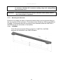
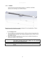
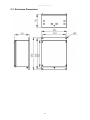
Installation & Operating Manual iWAP300 1 Operating Manual This page is intentionally left blank. Document Number 316134 (See Last Page for Revision Details) ©2006 Extronics Limited. This document is Copyright Extronics limited. Extronics reserve the right to change this manual and its contents without notice, the latest version applies. 2 Operating Manual Contents 1 2 3 4 5 6 7 8 Introduction.......................................................................................................... 4 Safety Information and Notes .............................................................................. 5 2.1 Storage of this Manual................................................................................... 5 2.2 List of Notes .................................................................................................. 5 Installation and Setting-to-Work .......................................................................... 6 3.1 Installation ..................................................................................................... 6 3.1.1 Removing the cover ................................................................................ 6 3.1.2 Fitting the cables ..................................................................................... 7 3.1.3 Mains & PoE Variant Cable Installation .................................................. 7 3.1.4 Fibre Ethernet Input ................................................................................ 9 3.1.5 24VDC Variant Cable Installation............................................................ 9 3.1.6 Fibre Ethernet Input .............................................................................. 11 3.1.7 Thermostat Control ............................................................................... 11 3.1.8 Fitting the Antennas .............................................................................. 11 3.1.9 Mounting the Antennas ......................................................................... 12 3.1.10 Setting to work ................................................................................... 13 Intended Purpose Usage ................................................................................... 14 4.1 Transportation and Storage ......................................................................... 14 4.2 Authorized Persons ..................................................................................... 14 4.3 Cleaning and Maintenance .......................................................................... 14 4.4 Safety Precautions ...................................................................................... 14 4.5 Cleaning and Maintenance Intervals ........................................................... 15 4.6 Aggressive substances and environments .................................................. 15 4.7 Exposure to external stresses ..................................................................... 15 Technical Data .................................................................................................. 16 5.1 Specification ................................................................................................ 16 5.2 Enclosure Dimensions ................................................................................. 17 5.3 EC Declaration of Conformity ...................................................................... 18 Type Codes ....................................................................................................... 19 Warranty Information ......................................................................................... 20 Manual Revision ................................................................................................ 21 3 Operating Manual 1 Introduction The iWAP300 Universal Industrial Access Point Enclosure is designed to deploy wireless networks in harsh, wet and corrosive environments. The concept allows installation of equipment from leading WLAN vendors such as Aeroscout, Meru, Symbol, Cisco, Firetide and many others. Each type of Access Point or RF transmitting device is rigorously checked and tested by Extronics to ensure that the vendors equipment is suited. This means that you can effectively use the vendor of your choice when you want to extend your WLAN to your plant areas where protection against the elements is essential. The Extronics iWAP300 is designed for use with Extronics extensive range of antennas for optimum coverage. Optional features include surge arrestors for lightening suppression in outdoor installations and multimode fibre inputs for the Ethernet, enclosure heater for low temperature and anti-condensation plus the option of plug and socket cable entry instead of cable glands. 4 Operating Manual 2 Safety Information and Notes 2.1 Storage of this Manual Keep this user manual safe and in the vicinity of the device. All persons who have to work on or with the device should be advised on where the manual is stored. 2.2 List of Notes The notes supplied in this chapter provide information on the following. Danger / Warning. o Possible hazard to life or health. Caution o Possible damage to property. Important o Possible damage to enclosure, device or associated equipment. Information o Notes on the optimum use of the device Warning! The iWAP300 must not be operated in the hazardous area. Important The technical data indicated on the iWAP enclosure must be observed. Important Changes in the design and modifications to the equipment are not permitted. This includes adding or removing heaters/fans which were installed by Extronics Ltd. Changing the pre installed Access points and/or MESH routers is NOT permitted. Important The iWAP300 shall be operated as intended and only in an undamaged condition. Caution When powering the iWAP300 via POE do not apply an external power supply to the protection board. Caution Never power the iWAP300 (if fans and/or heaters are installed) via POE. Important The nylon washers on the underside of the enclosure lid must be used with the gasket to maintain the IP rating of the enclosure. Important Antennas connections must sealed once installed to prevent the ingress of moisture. Standard RF connector sealing using self amalgamating tape should be used 5 Operating Manual 3 Installation and Setting-to-Work 3.1 Installation The iWAP300 is simple to install and can be secured directly to suitable surface using the mounting holes on the Enclosure. 3.1.1 Removing the cover Unscrew the four screws and remove the enclosure lid. Lid screws Lid screws R1-C R1-B R1-A Ethernet /Fibre Cable Entry R2-C R2-B R2-A AC/DC Power Cable Entry See table below for antenna connections: Antenna Connection R1-A R1-B R1-C Number of N-type connectors ordered for Radio 1 (2.4GHz Default) 0 1 2 3 x x x x x x Antenna Connection R2-A R2-B R2-C Number of N-type connectors ordered for Radio 2 (5GHz Default) 0 1 2 3 x x x x x x Note: For Radio 1 (R1) and Radio 2 (R2) on any manufacturers Wireless Access point, A will be antenna port 1, B will be antenna port 2, and C will be antenna port 3. For example: If you have ordered 1 N-type connector for Radio 1, and 2 N-type connectors for Radio 2. Then R1-A will be connected to antenna port 1 of Radio 1, R2-A will be connected to antenna port 1 of Radio 2, and R2-B will be connected to antenna port 2 of Radio 2 for any manufacturers wireless access point. 6 Operating Manual 3.1.2 Fitting the cables Depending on the configuration of the iWAP300, the connections for power and communication will need to be terminated into the enclosure via the correct cable entries shown in Diagram 3.1.1. The cables used to connect the power and/or Ethernet connection to the PCB screw terminals must conform to the following specification; All wires should be stripped and, if stranded cable is used, should be crimped using 2.5mm bootlace ferrules. The stripped/crimped wires should then be placed into the corresponding screw terminal and securely screwed in place. If using solid core cable; Minimum cross section of cable = 0.2mm2 Maximum cross section of cable = 2.5mm2 If using crimped stranded core cable; Minimum cross section of cable = 0.25mm2 Maximum cross section of cable = 1.5mm2 IMPORTANT! All cables should be connected to the iWAP300 via the correct cable gland, fitted by a competent person. IMPORTANT! Changes in the design and modifications to the equipment are not permitted. This includes adding heaters/fans which are not installed at the factory. Important The installer MUST ensure that that all cables have adequate mechanical protection to avoid damage to the wires. 3.1.3 Mains & PoE Variant Cable Installation Diagram 3.1.3.1 shows the connectors on the mains and PoE variant of the iWAP300. Table 3.1.3.2 describes the pin out connection required for operation. There are two blocks of screw terminals and one RJ45 connector. The Ethernet input screw terminals are wired in parallel with the RJ45 connector. Do not make an Ethernet connection to the RJ45 connector and the screw terminals at the same time, the installer should use only one of these connectors. Follow the instructions in section 3.1.2 to correctly prepare the cables and feed them through the correct cable gland. Follow table 3.1.3.2 to connect the correct cable to the correct screw terminal. If using the RJ45 connector instead of the screw terminals simply connect the Cat-5 cable to the connector and ensure the cable is securely in place. Caution Only ever make one Ethernet cable to either the RJ45 connector or Ethernet screw terminals – NEVER both. 7 Operating Manual Tx Rx LNE Fibre input Ethernet & PoE Input (RJ45) Ethernet & PoE Input (Screw Terminals) Chassis 110/230VAC Earth Input Diagram 3.1.3.1 – Mains Variant & PoE iWAP200 PCB Connector Description Notes 110/230VAC input These screw terminals allow the connection of a 110/230VAC power supply. Pinouts are; 1 = Live, 2 = Neutral, 3 = Earth. If AC powered, no PoE is required. Do not apply AC voltage if powering with PoE Chassis Earth There are two terminals which allow a connection to earth. When the iWAP300 is delivered one of these terminals will be connected to the enclosure. The second earth terminal spare. Connect a Cat-5 cable to these screw terminals for the connection of the Ethernet input. The pinouts on this terminal correspond with the standard cat-5 TIA/EIA-568-B T568B wiring methods. Ethernet & PoE Input (Terminals) Ethernet & PoE Input (RJ45) This allows the connection of a standard Cat-5 cable with plugs. Fibre Input Allows a fibre connection to be made to the iWAP300 board. The connector will be a ST connector for multimode fibre input, or a SC connector for single mode fibre Only one Ethernet input should be made, only use either the terminals or RJ45 connector NOT both. Only one Ethernet input should be made, only use either the terminals or RJ45 connector NOT both. The copper Ethernet input is disabled if the fibre module is fitted Table 3.1.3.2 – iWAP300 Mains / PoE Variant Pinouts 8 Operating Manual Important Only connectors 110/230VAC Input, Chassis Earth and Ethernet Input (Terminals or RJ45) are user serviceable. The end user should not connect, disconnect or alter the wiring on any other connector! Caution When powering the iWAP300 via POE do not apply an external power supply to the protection board. Caution Never power the iWAP300 via POE if fans and/ or heaters are installed. 3.1.4 Fibre Ethernet Input Important When connecting the access point via a fibre connection do not use any of the two Ethernet inputs of connectors. To obtain greater wired link distances the iWAP300 can be shipped with an optional fibre module. The fibre module will be connected directly to the access point, the user should attach the fibre cable directly to the fibre module. The fibre cable should be fed through the Ethernet cable gland. If a multimode fibre option has been specified the connection is mage via a “ST” connector. If a single mode fibre option has been specified, the connection is made via a “SC” connector. Important 3.1.5 The fibre cable must enter the iWAP300 enclosure via a cable gland, it therefore may be necessary to terminate the Fibre cable, with the correct connector, from within the enclosure after the cable has been fed through the cable gland. 24VDC Variant Cable Installation Diagram 3.1.3 shows the connectors on the mains variant of the iWAP300. Table 3.1.3 describes the pin out connection required for operation. There are two blocks of screw terminals and one RJ45 connector. The Ethernet input screw terminals are wired in parallel with the RJ45 connector. Do not make an Ethernet connection to the RJ45 connector and the screw terminals at the same time, the installer should use only one of these connectors. Follow the instructions in section 3.1.2 to correctly prepare the cables and feed them through the correct cable gland. Follow table 3.1.3 to connect the correct cable to the correct screw terminal. If using the RJ45 connector instead of the screw terminals simply connect the Cat-5 cable to the connector and ensure the cable is securely in place. Caution Only ever connect one Ethernet cable to either the RJ45 connector or Ethernet screw terminals. 9 Operating Manual Ethernet Input (RJ45) Optional Fibre Ethernet Input Input/Output (Screw Terminals) Module Chassis Earth 24 VDC Input Diagram 3.1.3 – 24V Variant iWAP300 PCB Connector Description Notes 24VDC input These screw terminals allow the connection of a 24VDC power supply. Pinouts are; 1 = +24V, 2 = 0V/GND, 3 = Earth/cable outer sheath. There are two terminals which allow a connection to earth. When the iWAP300 is delivered from Extronics’ factory one of these terminals will be connected to the enclosure. The second earth terminal spare. Connect a Cat-5 cable to these screw terminals for the connection of the Ethernet input. The pinouts on this terminal correspond with the standard Cat-5 TIA/EIA-568-B T568B wiring methods. This allows the connection of a standard Cat-5 Only one Ethernet input should be made, only use either the terminals or RJ45 connector NOT both. Only one Ethernet input Chassis Earth Ethernet Input (Terminals) Ethernet Input 10 Operating Manual (RJ45) cable with plugs. should be made, only use either the terminals or RJ45 connector NOT both. Table 3.1.3 – iWAP300 24VDC Variant Pinouts Important Only connectors 24VDC Input, Chassis Earth and Ethernet Input (Terminals or RJ45) are user serviceable. The end user should not connect, disconnect or alter the wiring on any other connector! Caution When powering the iWAP300 via POE do not apply an external power supply to the protection board. Caution Never power the iWAP300 (if fans and/or heaters are installed) via POE. 3.1.6 Important Fibre Ethernet Input When connecting the access point via a fibre connection do not use any of the two Ethernet inputs of connectors. To obtain greater wired link distances the iWAP300 can be shipped with an optional fibre module. The fibre module will be connected directly to the access point, the user should attach the fibre cable directly to the fibre module using a multimode fibre cable on an ST connector. 3.1.7 Thermostat Control The thermostats are currently not user configurable. The default configuration is for the heaters to be turned on when the internal ambient temperature is between -20oC and +10oC and for the fans/wireless hardware to be on above 1.5oC 3.1.8 Fitting the Antennas Connect the antennas to the correct the N type connector on the outside of the enclosure (see Diagram 3.1.1). Make sure to only connect antennas which are intended to be used at the frequency required (i.e. either 2.4GHz or 5.8GHz antennas). Depending on the options ordered some of the N-types may have been replaced with blanking plugs or surge arrestors. If the version ordered contains both a mesh router and access point; the mesh router and access point should be setup in software to run at 5.8GHz and 2.4GHz respectively. The iWAP200 will be wired in this way when delivered. 11 Operating Manual Important Information 3.1.9 Antennas connections must sealed once installed to prevent the ingress of moisture. Standard RF connector sealing using self amalgamating tape should be used Do not exceed the Effective Isotropic Radiated Power (EIRP) limit for the country/region of operation Mounting the Antennas Extronics can supply two sizes of antenna brackets which can be mounted either on the top or bottom of the enclosure. The bracket sizes offered are 365mm and 680mm in length. The brackets allow the mounting of two antennas (either the iANT100 or iANT200) at the far extremities of the bracket. 3.1.9.1 iANTMB02 316L SS Antenna bracket 365mm length for 2 iANT100 / iANT200 antennas for mounting on an iWAP enclosure 12 Operating Manual 3.1.9.2 iANTMB03 316L SS Antenna bracket 365mm length for 3 iANT100 / iANT200 antennas for mounting on an iWAP enclosure Bespoke mounting brackets can also be designed for most applications. Please contact Extronics for more information. 3.1.10 Setting to work Once all cables are connected correctly, refit the enclosure lid using the four screws previously removed. Use a torque screwdriver set to 2.5 Nm. Do not over tighten screws. Refer to the original manufacturer’s instructions for detailed information on setting the network to work correctly. Note! Ensure the lid is secure, correct cable glands are fitted and the unit device correctly wired and earthed for the particular application before applying power Note! Ensure that the lid gasket is clean and undamaged before fitting the lid. 13 Operating Manual 4 Intended Purpose Usage Important Before setting the units to work read the technical documentation carefully. Important The latest version of the technical documentation or the corresponding technical supplements is valid in each case. The iWAP300 is built using modern components and is extremely reliable in operation; however it must only be used for its intended purpose. Please note that the intended purpose also includes compliance with the instructions issued by the manufacturer for installation, setting up and service. Any other use is regarded as conflicting with the intended purpose. The manufacturer is not liable for any subsequent damage resulting from such inadmissible use. The user bears the sole risk in such cases. 4.1 Transportation and Storage All iWAP300 devices must be so transported and stored that they are not subjected to any excessive mechanical stresses. 4.2 Authorized Persons Only persons trained for the purpose are authorized to handle the iWAP300; they must be familiar with the unit and must be aware of the regulation and provisions required for correct installation as well as the relevant accident prevention regulations. 4.3 Cleaning and Maintenance The iWAP300 and all its components require no maintenance and are selfmonitoring. All work on the iWAP300 by personnel who are not expressly qualified for such activities will cause the guarantee to become void. 4.4 Safety Precautions Important For the installation, maintenance and cleaning of the units, it is absolutely necessary to observe the applicable regulations as well as the Accident Prevention Regulations. 14 Operating Manual 4.5 Cleaning and Maintenance Intervals The cleaning intervals depend on the environment where the system is installed. 4.6 Aggressive substances and environments The iWAP300 is not designed to come into contact with aggressive substances or environments, please be aware that additional protection may be required. 4.7 Exposure to external stresses The iWAP300 is not designed to be subjected to excessive stresses e.g. vibration, heat, impact. Additional protection is required to protect against these external stresses. The iWAP300 will require additional protection if it is installed in a location where it may be subjected to damage. 15 Operating Manual 5 Technical Data 5.1 Specification Power Supply Universal 90-264VAC, 20-28VDC or IEEE802.3af POE Maximum Power Consumption Without heating or cooling POE 802.3af or 16W for mains or DC power With cooling 21W With heating and cooling 121W Enclosure Material 316L Stainless Steel Ingress Protection IP66 Weight Approximately 10 Kg Dimensions 390 x 286 x 161 mm (h x w x d) Environmental Typical Operating Temperature (actual temperature range dependant upon access point used, see overleaf): Without heating or cooling –20oC to 500C With cooling –20oC to 600C With heating and cooling –40oC to 600C Storage temperature; –40oC to 700C Relative humidity; 0 to 95%, non condensing Note: If fibre option chosen the minimum ambient temperature is 0oC. If a lower ambient temperature is required heaters MUST be fitted Input Connections 115V/230VAC input option on screw terminals 24VDC input option on screw terminals 10/100BaseT Ethernet on RJ45 socket and screw terminals 10/100BaseFX Multimode fibre input option on ST connectors 100BaseLX-10 Single mode fibre on SC connectors Output Connections Up to 6 external RF outputs via external N-type RF connectors. Surge arrestors are optional. Customer is to specify the number of required RF outputs Ethernet Link distance 10/100Base T Ethernet on Cat5e: up to 0.1km 10/100BaseFX on Multimode Fibre: Up to 2km 100Base-LX10 on Single mode fibre: up to 10km Maximum Internal RF Cable Loss 2.4GHz (between output of access point External N-type output 1.2dB and external N-type connector) With Surge Arrestor 1.55dB 5.0Ghz 1.40dB 1.75dB 5.8GHz 1.60dB 1.95dB Radio Dependant upon chosen hardware Antennas To be used with up to 6 antennas (not included) e.g. Extronics iANT200 series or any other standard antenna. 16 Operating Manual 5.2 Enclosure Dimensions 17 Operating Manual 5.3 EC Declaration of Conformity 18 Operating Manual 6 Type Codes iWAP300 Universal Access Point Enclosure iWAP300-[#1]-[#2]-[#3]-[#4]-[#5]-[#6]-[#7]-[#8]-[#9] Specify option [#1] - Wireless Network Hardware Hardware supplied by customer* Hardware supplied by Extronics C E Specify option [#2] - Type Of Wireless Network Hardware Cisco AP1242 Access Point (No heating/Cooling: -20oC to 45oC, with heating/cooling -40oC to 55oC) Cisco AP1242 LAP Light Access Point (No heating/Cooling: -20oC to 45oC, with heating/cooling -40oC to 55oC) Acksys WLG-LINK-OEM (No heating/Cooling: -20oC to 60oC, with heating/cooling -40oC to 70oC) Firetide 7000 Series MESH Router (No heating/Cooling: 0oC to 50oC, with heating/cooling -40oC to 60oC) AeroScoout Location Receiver (No heating/Cooling: 0oC to 50oC, with heating/cooling -40oC to 60oC) 6 7 26** 30 31 **(Note: Acksys WLG-LINK-OEM is NOT currently compatible with an 802.3af POE input. For option #3 only AC or DC input may be chosen) *Extronics can supply the above wireless network hardware, alternatively you may wish to “free issue” one of the above solutions so that we can factory fit it. Please note that new hardware not already on the list above will need to be assessed to determine its suitability. Specify option [#3] - Power Supply Universal 90-264VAC (If heater option [#7] selected, the unit cannot have a universal voltage, it will be either 115VAC or 230VAC) 24V DC IEEE802.3af compliant Power-Over-Ethernet AC DC POE Note: If AC option is selected, the unit can be powered by either AC supply or POE supply Specify option [#4] - Ethernet Connection 10/100BaseT Ethernet on CAT5 copper Multimode 10/100BaseFX fibre with ST connector (Note : minimum ambient temperature 0 oC without heaters) Single mode 100BaseLX-10 fibre with SC connector (Note: minimum ambient temperature 0 oC without heaters) C F S Specify option [#5] - Number of Antenna Outputs for Radio 1 0 off N-type connector 1 off N-type connector 2 off N-type connector 3 off N-type connector 0 1 2 3 0 1 2 3 0S 1S 2S 3S off off off off N-type N-type N-type N-type connector connector connector connector with with with with surge surge surge surge protector protector protector protector Specify option [#6] - Number of Antenna Outputs for Radio 2 0 off N-type connector 1 off N-type connector 2 off N-type connector 3 off N-type connector 0 1 2 3 0 1 2 3 0S 1S 2S 3S off off off off N-type N-type N-type N-type connector connector connector connector with with with with surge surge surge surge protector protector protector protector Specify option [#7] - Enclosure Heating (not compatible with universal 90-264VAC or POE supplies) No enclosure heating 230VAC enclosure heating 115VAC enclosure heating 24VDC enclosure heating N H1 H2 H3 Specify option [#8] - Enclosure cooling (not compatible with POE supply) No enclosure cooling Enclosure cooling fitted N C Specify option [#9] - Enclosure Cable Entry Metal compression Cable glands fitted No Glands fitted, M20 entries provided for installer to provide own glands or blanking plugs/sockets G N Accessories Pipe mount bracket kit to enable the unit to be fixed to a pipe or rectangular post. (2 kits required for complete fitment) iWAPMB01 19 Operating Manual 7 Warranty Information The Customer shall carry out a thorough inspection of the delivered project or equipment with 21 days of delivery and shall give immediate written notification to the Company of any omissions, defects or faults. The Company warrants that the project or equipment delivered shall accord with the Quotation or Pricing Schedule and related Company specifications, but it does not warrant its fitness for any other purpose. Extronics will make good, by repair or at Extronics option by the supply of a replacement, defects which, under proper use in accordance with specifications and manufacturer’s instructions, appear in the goods within a period of twelve calendar months after the goods have been delivered and arise solely from faulty design, materials or workmanship, provided always that defective parts have been returned to Extronics if Extronics shall have so required. The warranty of any goods is based upon a return to Extronics factory (Return to Base Warranty) which will be at the Customers cost. The repaired or new parts will be delivered by Extronics carriage paid. If you allege that goods are totally unfit for their purpose they must be returned within 7 days of receipt. Site Warranty is expressly excluded from these terms and conditions unless agreement is made in writing between the parties it. Extronics liability under this clause shall be in lieu of any warranty or condition implied by law as to the quality or fitness for any particular purpose of the goods, and save as provided in this clause Extronics shall not be under any liability, whether in contract, or otherwise, in respect of defects in goods delivered or for any injury other (than personal injury caused by Extronics negligence as defined in Section 1 of the Unfair Contract Terms Act, 1977), damage or loss resulting from such defects or from any work done in connection therewith, provided however that nothing in this clause shall operate to exclude any warranty or condition implied by law as to the quality of the goods in the event that the goods when sold by you or when sold by any person or persons to whom you may sell the goods shall become the subject of a consumer sale as defined in the Supply of Goods (Implied Terms) Act, 1973 except that any claim under such warranty or condition shall have arisen from any act or omission by you or by any person or persons selling the goods by way of a consumer sale. 20 Operating Manual 8 Manual Revision Revision 01 02 03 04 05 06 07 Description Initial Release Revised To Show Non Wireless Backhaul New Picture On Front Cover Various changes throughout Updated Added DoC, added MB03 bracket, updated type codes, adding note about sealing RF connections. Added Warranty information Added antenna mounting brackets and 6 antenna outputs. Updated AC/POE information 21 Date 15/12/06 23/02/07 20/04/07 13/11/08 30/07/11 28/03/2012 By DJR NJS JE JE NE AJR 07/03/2013 AJR