1
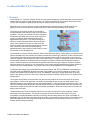
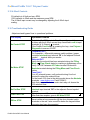
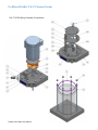
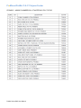
ProMinent ProMix ‘S & C’ Polymer Feeder Operating Instructions ProMinent® ProMix-S & C Polymer Blending Systems Please completely read through these operating instructions first! Do not discard! The warranty shall be invalidated by damage caused by operating errors! ProMix_S&C_IOM (11/20/14): – P/N: XXXXXX-(Rev-A) ProMinent Fluid Controls, Inc. (USA) 136 Industry Drive, Pittsburgh, PA 15275 Tel: (412) 787-2484 ProMix Series S&C User Manual www.prominent.us Fax: (412) 787-0704 ProMinent ProMix ‘S & C’ Polymer Feeder Table of Contents i. Overview: ............................................................................................................................................... 4 ii. ProMix S Systems with Peristaltic Pumps: ............................................................................................. 5 ii. ProMix S Systems with Diaphragm Pumps: ........................................................................................... 6 ii. ProMix C Systems with Peristaltic Pumps: ............................................................................................ 7 ii. ProMix C Systems with Diaphragm Pumps: .......................................................................................... 8 iii. Peristaltic Polymer Pumps used on S & C Models: ............................................................................... 9 iv. Diaphragm Polymer Pumps used on S & C Models: ............................................................................ 10 1.0 INSTALLATION & QUICK START GUIDE ......................................................................................... 11 1.1 Safety:............................................................................................................................................ 11 1.2 Delivery & Storage Checklist: ......................................................................................................... 11 1.3 Installation Considerations: ............................................................................................................ 11 1.4 Installation: ..................................................................................................................................... 12 1.5 Quick Start Guide: .......................................................................................................................... 13 1.6 ProMix Options for Polymer Settings and Controller Door Switches .............................................. 14 1.7 Servicing Guidelines:...................................................................................................................... 14 2.0 CONTROLLER .................................................................................................................................. 16 2.1 Keypad Navigation ......................................................................................................................... 16 2.2 Main Menu ..................................................................................................................................... 17 2.3 Adjust Setpoint ............................................................................................................................... 18 2.4 Modify Timing ................................................................................................................................. 19 2.5 Manually Flush Mixer .................................................................... 22Error! Bookmark not defined. 2.6 Automatic Flush Mixer .................................................................................................................... 22 2.7 Status Message Summary.............................................................................................................. 23 2.8 Calibrate 4-20mA Input................................................................................................................... 24 2.9 Scale the 4-20mA Input .................................................................................................................. 25 2.9 Scale the 4-20mA Input (continued) ............................................................................................... 26 2.10 Response on Loss of 4-20 mA Input ............................................................................................. 27 2.11 Calibrate 4-20mA Output .............................................................................................................. 28 2.12 Operation Configuration ............................................................................................................... 29 2.13 Feed Verification .......................................................................................................................... 25 2.15 4-20mA Controls .......................................................................................................................... 26 ProMix Series S&C User Manual ProMinent ProMix ‘S & C’ Polymer Feeder 2.16 Troubleshooting Guide ................................................................................................................. 26 2.17 Diagnostic Display ........................................................................................................................ 27 2.18 Blue White A-100NV Pump .......................................................................................................... 28 3.0 SPARE PARTS & PREVENTIVE MAINTENANCE ............................................................................ 29 3.1 BLUE WHITE A-100NV Pump Spare Parts .................................................................................... 29 3.2 PVC Mixing Chamber Spare Parts ................................................................................................. 29 3.3 Piping Components Spare Parts ..................................................................................................... 29 3.4 Control Panel Spare Parts .............................................................................................................. 29 3.5 Maintenance and Lubrication Schedule .......................................................................................... 30 Appendix A - TA Series Bill of Material .................................................................................................... 30 Appendix B – Control Panel “A Controls” ................................................................................................. 36 B.2 Control Panel Drawings ................................................................................................................. 36 B.3 4-20 mA Input Scaling .................................................................................................................... 42 Appendix C – Polymer Sizing / Dosage .................................................................................................... 43 Appendix D – Reference Documents ....................................................................................................... 44 Appendix E - Keypad Menu Overview ..................................................................................................... 45 ProMix Series S&C User Manual ProMinent ProMix ‘S & C’ Polymer Feeder i. Overview: The ProMix S & C “TA Series” Polymer Feeder is a skid system designed to control feed water and polymer and combine them to produce a high quality solution. The system is designed to receive liquid neat polymer while mixing it with feed water to produce and discharge a quality solution from the system. Research in the science of polymer activation indicates that the activation energy must decrease as the polymeric chain is uncoiled to prevent rupture and hence decrease the performance of the product. The mixing by the Polymer Feeder is accomplished mechanically with three distinct mixing zones separated by baffles. The first zone consists of a fast mixing blade that delivers high shear at the precise point of polymer injection, creating an immediate dispersion before agglomeration takes place. The second mixing zone induces a vortex and draws solution down through the center of the chamber from zone one and forces the solution outward to the sides and then down into the third zone. Finally, the third zone mixing blade gently agitates/blends the active polymer solution before it exits the chamber via the discharge tube. The ProMix S & C Polymer Feeder controller offers several operating options. These options are selected using various combinations of the controller door switch positions and polymer type selections via the controller menu. The controller allows the polymer pump speed to be controlled either locally via the keypad or remotely via a customer supplied 4-20 mA signal over a 0 to 100% speed range. The polymer dosage rate must be calculated and the pump adjusted for the desired ratio concentration of polymer to dilution water leaving the feeder by volume. Different maximum concentrations are possible based upon the type of polymer. Emulsion polymers should be limited to a maximum of 1% concentration in the mixing chamber and Mannich polymers should not exceed 10% in the mixing chamber. The polymer type to be used is selectable from the keypad menu. The System Start switch on the controller door has three positions, ON, OFF and REMOTE. ON enables the controller locally and REMOTE allows the controller to be enable via a customer supplied dry contact. The Polymer Pump switch has two positions, LOCAL and REMOTE. Placing the System Start switch in the OFF position after having first been in either of the other two positions will initiate a flush cycle for the system before shutting down. The Polymer Pump switch on the controller front door has two positions to choose the source of the pump control signal. In the LOCAL position the controller uses the keypad entry for polymer pump speed. In the REMOTE position a user supplied 4-20 mA signal representing 0 – 100% pump speed controls the pump. The user must manually adjust the primary and post dilution valves for the desired dilution water flow rate and must calculate the required pump speed to attain the desired concentration. Rotameters are provided to monitor the dilution water flow rates. The ProMix Polymer Feeder is equipped with all the necessary components for easy installation, reliable performance and safe operation. The design incorporates an electric solenoid valve (water inlet), flow meter/switch, manually adjustable rotameters for primary and secondary dilution flow, either a peristaltic or diaphragm type neat polymer pump (depending on model), microprocessor based controller, manual ball valves, pump calibration column, PVC piping and components, and polymer mixing chamber mounted on a skid to facilitate proper mixing and delivery. ProMix Series S&C User Manual ProMinent ProMix ‘S & C’ Polymer Feeder ii. ProMix S Systems with Peristaltic Pumps: Peristaltic Pump Type Blue-White (A-100NV Series): PART NUMBER MODEL PUMP TYPE MAX CAPACITY 1048346 60X1-0.22TA Blue White A1N00V-1T 0.22 GPH 1048347 60X2-0.95TA Blue White A1N30V-1T 0.95 GPH 1048348 120X2-0.95TA Blue White A1N30V-1T 0.95 GPH 1048349 120X2-2.00TA Blue White A1N30V-2T 2.00 GPH 1048351 300X2-2.00TA Blue White A1N30V-2T 2.00 GPH 1048352 300X2-3.73TA Blue White A1N20V-3T 3.73 GPH **Refer to Appendix C for proper sizing** Overall Skid Dimensions .................................................................. 24” x 34” x 66” (L x W x H) Overall Weight of Skid ...................................................................................... Approx 170 lbs. Power Requirements .......................................................... 120 VAC, 60 Hz, 1 Phase, 15 Amp Control panel FLA ................................................................................................... 11.2 Amp Volume of Mixing Chamber ..................................................................................... 2.0 Gallons Maximum Rated Chamber Pressure ......................................................................... 150 PSIG Maximum Operating Chamber Pressure .................................................................... 100 PSIG Normal Operating Pressure ....................... 50 PSIG or 65 PSIG (Depends on Pump Selected) Recommended Running Temperature .............................................................. +50°F to 100°F Water Connection Size ............................................................................................... ¾” FNPT Solution Discharge Connection Size .......................................................................... ¾” FNPT Neat Polymer Inlet Connection Size ............................................................................ ½” FNPT Drain Connection ......................................................................................................... ¼” FNPT ProMix Series S&C User Manual ProMinent ProMix ‘S & C’ Polymer Feeder ii. ProMix S Systems with Diaphragm Pumps: Diaphragm Pump Type ProMinent Delta Series: PART NUMBER MODEL PUMP TYPE MAX CAPACITY 1048353 60X1-1.01DA DLTA1608PVT4000UD4031EN0 1.01 GPH 1048354 60X2-1.01DA DLTA1608PVT4000UD4031EN0 1.01 GPH 1048355 120X2-1.01DA DLTA1608PVT4000UD4031EN0 1.01 GPH 1048356 120X2-2.30DA DLTA1020PVT4000UD4031EN0 2.30 GPH 1048357 300X2-2.30DA DLTA1020PVT4000UD4031EN0 2.30 GPH 1048358 300X2-3.70DA DLTA0730PVT4000UD4031EN0 3.70 GPH **Refer to Appendix C for proper sizing** Overall Skid Dimensions ................................................................. 24” x 34” x 66” (L x W x H) Overall Weight of Skid ...................................................................................... Approx 170 lbs. Power Requirements .......................................................... 120 VAC, 60 Hz, 1 Phase, 15 Amp Control panel FLA ................................................................................................... 11.5 Amp Volume of Mixing Chamber ..................................................................................... 2.0 Gallons Maximum Rated Chamber Pressure ......................................................................... 150 PSIG Maximum Operating Chamber Pressure .................................................................... 100 PSIG Normal Operating Pressure ....................................................................................... 100 PSIG Recommended Running Temperature .............................................................. +50°F to 100°F Water Connection Size ............................................................................................... ¾” FNPT Solution Discharge Connection Size .......................................................................... ¾” FNPT Neat Polymer Inlet Connection Size ............................................................................ ½” FNPT Drain Connection ......................................................................................................... ¼” FNPT ProMix Series S&C User Manual ProMinent ProMix ‘S & C’ Polymer Feeder ii. ProMix C Systems with Peristaltic Pumps: Peristaltic Pump Type Blue-White (A-100NV Series): PART NUMBER MODEL PUMP TYPE MAX CAPACITY 1048360 60X1-0.22TA Blue White A1N00V-1T 0.22 GPH 1048361 60X2-0.95TA Blue White A1N30V-1T 0.95 GPH 1048362 120X2-0.95TA Blue White A1N30V-1T 0.95 GPH 1048363 120X2-2.00TA Blue White A1N30V-2T 2.00 GPH 1048364 300X2-2.00TA Blue White A1N30V-2T 2.00 GPH 1048365 300X2-3.73TA Blue White A1N20V-3T 3.73 GPH **Refer to Appendix C for proper sizing** Overall Skid Dimensions ................................................................. 26” x 24” x 50” (L x W x H) Overall Weight of Skid ...................................................................................... Approx 130 lbs. Power Requirements .......................................................... 120 VAC, 60 Hz, 1 Phase, 15 Amp Control panel FLA ................................................................................................... 11.2 Amp Volume of Mixing Chamber ..................................................................................... 2.0 Gallons Maximum Rated Chamber Pressure ......................................................................... 150 PSIG Maximum Operating Chamber Pressure .................................................................... 100 PSIG Normal Operating Pressure ....................... 50 PSIG or 65 PSIG (Depends on Pump Selected) Recommended Running Temperature .............................................................. +50°F to 100°F Water Connection Size ............................................................................................... ¾” FNPT Solution Discharge Connection Size .......................................................................... ¾” FNPT Neat Polymer Inlet Connection Size ............................................................................ ½” FNPT Drain Connection ......................................................................................................... ¼” FNPT ProMix Series S&C User Manual ProMinent ProMix ‘S & C’ Polymer Feeder ii. ProMix C Systems with Diaphragm Pumps: Diaphragm Pump Type ProMinent Delta Series: PART NUMBER MODEL PUMP TYPE MAX CAPACITY 1048460 60X1-1.01DA DLTA1608PVT4000UD4031EN0 1.01 GPH 1048461 60X2-1.01DA DLTA1608PVT4000UD4031EN0 1.01 GPH 1048462 120X2-1.01DA DLTA1608PVT4000UD4031EN0 1.01 GPH 1048463 120X2-2.30DA DLTA1020PVT4000UD4031EN0 2.30 GPH 1048474 300X2-2.30DA DLTA1020PVT4000UD4031EN0 2.30 GPH 1048475 300X2-3.70DA DLTA0730PVT4000UD4031EN0 3.70 GPH **Refer to Appendix C for proper sizing** Overall Skid Dimensions ................................................................. 26” x 24” x 50” (L x W x H) Overall Weight of Skid ...................................................................................... Approx 170 lbs. Power Requirements .......................................................... 120 VAC, 60 Hz, 1 Phase, 15 Amp Control panel FLA ................................................................................................... 11.5 Amp Volume of Mixing Chamber ..................................................................................... 2.0 Gallons Maximum Rated Chamber Pressure ......................................................................... 150 PSIG Maximum Operating Chamber Pressure .................................................................... 100 PSIG Normal Operating Pressure ....................................................................................... 100 PSIG Recommended Running Temperature .............................................................. +50°F to 100°F Water Connection Size ............................................................................................... ¾” FNPT Solution Discharge Connection Size .......................................................................... ¾” FNPT Neat Polymer Inlet Connection Size ............................................................................ ½” FNPT Drain Connection ......................................................................................................... ¼” FNPT ProMix Series S&C User Manual ProMinent ProMix ‘S & C’ Polymer Feeder iii. Peristaltic Polymer Pumps used on S & C Models: Flowrate (GPH) Min Max Rated Rated Series Part Number Ident Code RPM Max Pressure (PSIG) A-100NV 7747012 A1N00V-1T 14 0.012 0.24 65 A-100NV 7747013 A1N30V-1T 60 0.053 1.06 65 A-100NV 7747014 A1N30V-2T 60 0.111 2.22 65 A-100NV 7747015 A1N20V-3T 45 0.207 4.14 50 Notes: 1. Blue White Peristaltic Pumps 2. GPH Rating above based upon pumping Water not Polymer 3. Power Requirements: 120VAC, 60Hz, Single Phase (0.35 Amp) 4. Suction Lift Capabilities: Approx 30ft. (based on water) 5. Tubing: Tygothane ProMix Series S&C User Manual ProMinent ProMix ‘S & C’ Polymer Feeder iv. Diaphragm Polymer Pumps used on S & C Models: Factory SPM Default Max Mode Flowrate (GPH) Min @ Max @ 100% 100% Stroke Stroke Pressure (PSIG) Series Identification Code DLTA DLTA1020PVT4600UD4031EN0 HV2 120 0.008 1.01 145 DLTA DLTA1020PVT4600UD4031EN0 HV2 120 0.019 2.30 145 DLTA DLTA0730PVT4600UD4031EN0 HV2 120 0.031 3.70 102 Notes: 1. ProMinent - Delta Solenoid Driven Metering Pump 2. Original Pump GPH rating is derated 20% due to Polymer viscosity. The actual deration may vary depending on the polymer used 3. Control Modes Available * a. Standard – 200 spm: 0-50 cp b. HV1 (slightly reduced discharge speed) – 160 spm: 50-200 cp c. HV2 (moderately reduced discharge speed) – 120 spm: 200-500 cp d. HV3 (maximum reduced discharge speed)– 80 spm: 500-1000 cp 4. Connections: ½” x 3/8” or DN10 Depending on Model Selected 5. Power Requirements: 115VAC, 60 Hz, Single Phase * Viscosity values are approximate and can vary widely per specific application. Use these values as a guideline only and consult the factory for specific application capabilities ProMix Series S&C User Manual ProMinent ProMix ‘S & C’ Polymer Feeder 1.0 INSTALLATION & QUICK START GUIDE 1.1 Safety: Utilize appropriate protective safety gear when operating or maintaining this equipment. Recommended safety gear is as follows: Personal Protective Equipment (PPE): Hard Hats (Where overhead hazards exist) Safety Glasses with side shields PVC Apron PVC Gloves Safety-Toed Work Boots 1.2 Delivery & Storage Checklist: 1. Check packing list for completeness and note any missing items immediately. 2. Inspect equipment and shipping container for damages before accepting delivery. Make note of the carrier’s bill-of-lading the extent of the damage, if any, and notify the carrier. 3. Store the equipment on firm level surface in original packing container. Do not store the equipment where it may be exposed to extreme temperatures, precipitation, humidity, or dust. Avoid direct sunlight that could overheat and damage equipment. Ambient Conditions for storage and transport: Temperature: 14°F to 120°F Air Humidity: ≤ 92% relative humidity, non-condensing 1.3 Installation Considerations: Required Polymer System Voltage Available Water Pressure Injection Point Pressure Number of Injection Points Polymer Solution Discharge: For example (Length of Piping Run and Pipe Size) Neat Polymer Suction: Flooded or Lift Type of Application / Dewatering Device Type of Polymer: Emulsion, Dispersion, Solution ProMix Series S&C User Manual ProMinent ProMix ‘S & C’ Polymer Feeder 1.4 Installation: 1. Unpack and position equipment on sturdy level surface. Fasten to prevent movement. 2. Do not install equipment in areas of extreme heat, cold, dust or humidity. Avoid areas where objects or fluids can drop from overhead. 3. Units are to be installed as close to the point of application as possible. 4. Inlet pressure is not to exceed 100 psig working pressure. 5. System pressure at the discharge is not to exceed 80% of inlet pressure. 6. Piping Internal to the System: a. Inspect the piping for breakage. The system may have been jarred during shipping. b. Check the tightness on all unions. Hand tighten only – no tools. Unions incorporate an o- ring seal. Ensure that the o-ring is seated properly prior to tightening. 7. Piping External to the System (Reference Appendix A for connection location): a. Install piping so that connections properly meet system termination points. Do not “stretch” field installed piping to meet system termination points. Stressed piping will fail! b. Piping should be at a minimum ¾” to and from the piping on the system. c. Avoid getting dirt and debris inside the piping during installation. Plug ends of piping with rags if construction activities are underway. All debris must be flushed from piping before system start-up. d. Connect to outlet piping ¾” FNPT from static mixer to associated customer application point. e. Connect to make-up water inlet piping ¾” FNPT (5 GPM maximum at 100 psig maximum). f. Connect to Neat Polymer pump inlet piping ½” FNPT. g. Install ¾” pressure regulator and ¾” y-strainer / basket strainer on the clean make-up water line if equipment is currently not installed. (Recommended) h. Allow provisions for draining the system piping. Skid components will require maintenance. Ensure that chemicals can be evacuated from the skid piping and components for servicing. 8. Electrical Supply Needed for the System: a. Note: Review local Electrical Code and follow accordingly. b. Connect incoming power to skid mounted control panel (120VAC, Single Phase, 15 Amp, 60 Hz). Ensure panel is properly grounded. c. Check electrical connections to be sure proper voltage is supplied to the system. d. Power the unit using a dedicated, separate breaker in the local lighting distribution panel. e. Do not route the AC power in common conduit with variable frequency pump drives. f. Do not put conduit entries in the top of the control panel. Resulting conduit condensation and failure to seal may damage controller circuit boards. 9. The Overload relay should be set to the Motor Nameplate Full Load Amps. Setting this to a higher value will result in possible damage to the motor and associated wiring. Overload conditions should be investigated and possible process changes may need to be made to prevent overload conditions. 10. Connect Digital Remote Start Functions (note wiring termination points in Appendix B) for polymer tank level and remote start permissive. Default jumpers should remain in place for any input not available. 11. Refer to the Blue White A-100NV Installation & Maintenance Manual regarding pump information. ProMix Series S&C User Manual ProMinent ProMix ‘S & C’ Polymer Feeder 1.5 Quick Start Guide: 1. After the installation guidelines (Section 1.4) of the manual. 2. Open ball valve on the suction of the pump to allow chemical to flow into the system by gravity. If the application is suction lift then ensure liquid is present in pump suction. 3. Start up pumps at 100% stroke length and frequency to purge all air and prime the system. To prime the pump press and hold the PRIME button on the keypad until chemical is visible in the suction line. 4. Verify motor rotation on Mixing Chamber motor. Normal rotation is CCW. 5. Do not run the mixing chamber motor dry. Damage to the mechanical seal could occur. 6. Close the Post Dilution flow control valve and adjust the Primary Dilution flow control valve to obtain the flow range required. If additional dilution water is needed adjust the secondary accordingly. Primary Dilution Post Dilution ProMix S ProMix C CCC 7. Verify that the maximum polymer injection pump pressure is higher then the system pressure. 8. Perform pump calibration using drawdown calibration cylinder. 9. Check flow calibration and be sure pump meets or exceeds the rated flow capacity. 10. Check flows at 100% capacity. 11. In System Start ON and Polymer Pump LOCAL switch positions the neat polymer pump speed is adjusted manually using the controller keypad to change the pump rate from 0 to 100% of the pump rated output. 12. In System Start ON and Polymer Pump REMOTE switch positions the controller receives a remote customer supplied analog 4-20 mA signal to adjust the desired pump speed from 0 to 100% of the pump rated output. This remote 4-20 mA signal can be scaled at the controller to enhance the resolution of the pump output control and bias the pump response to the remote signal. A remote start permissive is optional – if used then System Start switch should be in the REMOTE position. 13. Confirm proper operation of all instrumentation. For example: Gauge, Rotometer switch, etc. 14. Input functions checked and simulated (remote start/stop, 4-20mA, etc.). 15. Output functions checked. 16. Test the operation of all remaining circuits. 17. Observe system to assure that nothing looks or sounds abnormal. ProMix Series S&C User Manual ProMinent ProMix ‘S & C’ Polymer Feeder 1.6 ProMix Controller Door Switches . Manually adjust the two door switches, ‘System Start’ and ‘Polymer Pump’ for the desired operating conditions: System Start door switch Permits use of remote contact to enable system operation in REMOTE position. Polymer Pump door switch Determines the set point for pump control action which can be from the keypad entry in LOCAL or from a 4-20 mA signal in REMOTE. door switch options System Start Polymer Pump ON-OFF-REMOTE LOCAL-REMOTE controller door switch controller door switch PROMIX OPERATION Remote Start Contact: N/A ON LOCAL Keypad Local Setpoint: 0 – 100% pump speed Remote Setpoint: N/A Max. chamber concentration: 1.0% Remote Start Contact: N/A ON REMOTE Keypad Local Setpoint: N/A Remote Setpoint: 4-20 mA = 0 –100% pump speed Max. chamber concentration: 1.0% Remote Start Contact: Close=start, open=stop REMOTE LOCAL Keypad Local Setpoint: 0 – 100% pump speed Remote Setpoint: N/A Max. chamber concentration: 1.0% Remote Start Contact: Close=start, open=stop REMOTE REMOTE Keypad Local Setpoint: N/A Remote Setpoint: 4-20 mA = 0–100% pump speed Max. chamber concentration: 1.0% 1.7 Servicing Guidelines: Disconnect electrical power to the equipment prior to servicing. Relieve all pressure from the unit prior to servicing. Close all suction and discharge valves. Verify dilution water is closed. ProMix Series S&C User Manual ProMinent ProMix ‘S & C’ Polymer Feeder Drain chemical/water from unit prior to disassembly. Maintain protective covers over all moving parts. Keep body parts, hair and foreign objects from contact with moving parts. Do not allow grease or oil to be used or stored around the feed equipment or chemicals. Review the Material Safety Data Sheets of the Polymer utilized and observe appropriate safety measures. Mineral Oil can be utilized to aid in the polymer cleaning process. Ensure all operating & maintenance personnel are instructed regarding the contents of this manual ProMix Series S&C User Manual ProMinent ProMix ‘S & C’ Polymer Feeder 2.0 CONTROLLER 2.1 Keypad Navigation The ProMinent ProMix S Polymer Feeder uses a fixed configuration to deliver the operation required to operate the feeder. The main board is not interchangeable with other ProMinent controller hardware. The top line of the main menu displays the current feeder state on power ON Press EXIT during any main menu display & you’ll return to the top of the menu & the current feeder state. The other main menu displays show information you’ll need to set & adjust feed rate and to verify flowswitch, 4-20mA in & out… ProMix Series S&C User Manual UP & DOWN to view options or to EDIT numbers Move RIGHT to select next field when EDITing ENTER to select an option & to execute EDITing EXIT to escape option, info display or EDITing EXIT goes to top of Main Menu ProMinent ProMix ‘S & C’ Polymer Feeder 2.2 Main Menu This is the power ON, top of the menu display. Press EXIT at any display to return here. Displays the Polymer feed rate 0-100% and the current state of the feeder. See 1.6 for complete state table. Displays the Polymer Pump feed rate 0-100% and the controlling 4-20mA current level, Press ENTER @ Polymer Pump to view-adjust the Manual Setpoint & Calibrate the 4-20mA controlling the pump. Mixer ON time resets to zero every time the Mixer turns OFF. Press ENTER during Remote RUN or Local RUN to turn OFF the Polymer pump and flush the mixer. The Remote Setpoint 4-20mA current loop controls the Polymer Pump in Remote RUN mode. Press ENTER to calibrate. Flowswitch ON time resets to zero every time the Flowswitch turns OFF. After 24 hours displays >1Day. The Remote Start contacts must be closed for the polymer feeder to run. Remote Start time resets to zero every time the contact set opens. We’re now back at the top of the main menu. Sidebar: Press ENTER at Polymer to view and adjust feeder Fill, Flush & Wait-for-Flow timing. Press ENTER & UP at Polymer to view feeder Diagnostics. Refer to 2.17 for Diagnostic displays. ProMix Series S&C User Manual ProMinent ProMix ‘S & C’ Polymer Feeder 2.3 Adjust Setpoint Press ENTER @ Polymer Pump to view or adjust the Local Setpoint. Local Setpoint may be adjusted at any time if Polymer Pump switch is set to Local mode. The present Local Setpoint is 25.0%. Press ENTER to adjust. Key RIGHT to move the cursor & UP or DOWN to change the digit. Key EXIT to abandon or ENTER to execute. Displays new, adjusted Local Setpoint. Press EXIT to return to main menu. If the Polymer Pump switch is in the Local position, any adjustment takes effect immediately, modifying the 4-20mA output to the pump. Sidebar: Local Setpoint only controls the polymer pump when the Auto-Manual switch is @ Local. If the Local Setpoint is @ 25% the 4-20 mA current output loop will be at 8mA (4mA + 0.25 x 16mA = 8mA). Remote Setpoint only controls the polymer pump when the Polymer Pump switch is @ Remote. The polymer pump speed is then controlled by the remote 4-20 mA signal. ProMix Series S&C User Manual ProMinent ProMix ‘S & C’ Polymer Feeder 2.4 Modify Timing Press ENTER @ Polymer to view or adjust the feeder timing. Fill Time is the time that the feeder waits to fill the feeder prior to turning on the Polymer Feed pump. This protects the mechanical seal of the mixer motor shaft by keeping it wet. Minimum time is 30 seconds for the first fill only. Thereafter this step is skipped if operation pauses unless electrical power to the controller is cycled. Key ENTER to modify. Flush Time is the time water flows after initiation of a Flush Cycle. This is a maintenance feature and can be manually initiated by (1) placing the controller door System Start Switch in the OFF position for more than 2 seconds or (2) by opening the remote start contact for longer than 2 seconds or (3) by using the keypad menu. Key ENTER to modify time. Wait for Flow may be adjusted to any time from 1 to 30 seconds. Press ENTER to adjust. Diagnostics displays the input current loop power voltage. Press ENTER to view diagnostic data set. Refer to 4.2 for detail. Interlock (CI) could be set to NO/NC using key Feed Verify ON/OFF could be set to ON using for pulse feedback from Metering pump (metering pump must have pulse (dry contact output) Feed Verify may be adjusted to any time from 1 to 300 seconds. Press ENTER to adjust ProMix Series S&C User Manual ProMinent ProMix ‘S & C’ Polymer Feeder Sidebar: Wait for Flow: Water inlet solenoid open, ON. Mixer and Polymer Pump both OFF. Factory default = 5 seconds. The 4-20mA current loop control input may be powered by the site control system or by the ProMix S 24VDC power supply. ProMix Series S&C User Manual ProMinent ProMix ‘S & C’ Polymer Feeder Press ENTER @ Polymer to view or adjust the Fill Time, Flush time or Wait for Flow time. All three times are adjusted in the same way. In this example we’ll press ENTER @ Fill Time. Key RIGHT to move the cursor & UP or DOWN to change the digit. Key EXIT to abandon or ENTER to execute. Displays new, adjusted Fill Time. Press EXIT to return to main menu. If you ENTER a time less than 1 second, the Fill Time will be set to 1 second. If you ENTER a time greater than 60 seconds, the Fill Time will be set to 60 seconds. Sidebar: Fill Time: Minimum = 1 second, Maximum = 60 seconds. Factory default = 30 seconds. Flush Time: Minimum = 1 second, Maximum = 120 seconds. Factory default = 60 seconds. Wait for Flow: Minimum = 1 second, Maximum = 30 seconds. Factory default = 5 seconds. ProMix Series S&C User Manual ProMinent ProMix ‘S & C’ Polymer Feeder 2.5 Manually Flush Mixer Press ENTER @ Mixer When the Mixer ON time display is alternating with the Flush on ENTER display. The polymer feed pump will turn OFF. The Mixer & water inlet solenoid will remain ON while the alternating Mixer display counts down the flush period. At the end of the Flush period the ProMix S will return to the Auto RUN or Manual RUN state unless the user: 1. Sets the Auto-Manual-OFF switch to OFF. 2. Shuts off the feeder inlet water. 3. Opens the Remote Start contacts. Sidebar: Flush Time: Minimum = 1 second, Maximum = 120 seconds. Factory default = 60 seconds 2.6 Automatic Flush Mixer In Local Mode After setting the System start selector switch to OFF position the unit will go through Automatic flush cycle and will stop after defined flush Time, the system will run again if the selector switch is back to ON position In Remote Mode After opening the remote contact the unit will go through Automatic flush cycle and will stop after defined flush Time, the system will run again if the remote contact is closed ProMix Series S&C User Manual ProMinent ProMix ‘S & C’ Polymer Feeder 2.7 Status Message Summary LCD Displays Feeder State Offline STOP Feeder powered. On-Off-Remote switch at Off. Lin<4mA, Fault On-Off-Remote switch at Auto and 420mA input less than 4 mA. Exits on 4-20mA >= 4 mA or On-Off-Remote= Off or Manual Flow Check Waits user set seconds for Flow switch contact set closed after Filling Mixer. Exits on flow switch closed or On-Off-Remote= Off No Water STOP Exits on flow switch closed or On-Off-Remote= Off Filling Mixer Inlet Solenoid ON & Mixer OFF. Waits user set seconds to fill mixer. Exits on On-Off-Remote= Off No Ext.Run STOP Polymer Pump, Mixer and Solenoid OFF Exits on Remote Start contacts closed or On-Off-Remote = Off Flushing Mixer Solenoid & Mixer ON. Polymer pump OFF. Exits on flush time expired or No flow or On-Off-Remote = Off Flush Fail STOP No Flow measured while flushing. Exits on flush time expired or flow measured or On-Off-Remote = Off Remote RUN Polymer pump @ 4-20mA input controlled setpoint. Exits on no flow, control<0%, flush, Remote Start open, or On-OffRemote = Off or Manual. Local RUN Polymer pump @ user setpoint. Exits on no flow, flush, Remote Start open or On-Off-Remote = Auto or Off. Flushed, Stopped Press the ENTER key to Run Flush ends. Polymer Pump, Mixer and Solenoid OFF Any key press restarts. Sidebar: Flow Check: The flow switch monitors dilution water flow into the mixer chamber. Filling Mixer: The mixer chamber is filled once after every power ON cycle. If you drain the mixer, switch the power OFF then ON to re-fill the mixer chamber. ProMix Series S&C User Manual ProMinent ProMix ‘S & C’ Polymer Feeder 2.8 Calibrate 4-20mA Input Press ENTER @ 4-20 mA Input to calibrate the 4-20mA current loop input from the site’s control system 4-20 mA Input may be calibrated at any time in Auto or Manual mode. The present 4-20 mA Input is 38.7%. Press ENTER to calibrate. Key RIGHT to move the cursor & UP or DOWN to change the digit. Key EXIT to abandon or ENTER to execute. Displays new, adjusted Remote Setpoint. Press EXIT to return to main menu. If the Local-Remote switch is in the Remote position, any adjustment takes effect immediately and modifies the 4-20mA output to the polymer pump. Sidebar: ‘Calibrate Iin’ matches the % display on the polymer feeder with the remote operator’s % display. The underlying 4-20mA level is of less importance than having both of the % displays (the feeder’s & the remote operator’s) match because the Polymer feed pump operates from OFF at 0% to maximum ON at 100%. It’s simpler to calibrate on a % instead of calibrating on a current and making a non-intuitive 4-20mA loop to 0-100% conversion. So you don’t need to know that a 32.4% feed corresponds to a current loop @ 9.18 mA. The factory default scales the 4-20 mA input for 4mA = 0% Pump to 20 mA = 100% Pump. See Section 2.2 if your site’s 4-20 mA input is not scaled 4-20 mA = 0 to 100% ProMix Series S&C User Manual ProMinent ProMix ‘S & C’ Polymer Feeder 2.9 Scale the 4-20mA Input Press ENTER @ 4-20 mA Input to navigate the input current loop sub-menu See the previous page for calibrating the 4-20 mA input loop Press DOWN to view the present 4 mA pump feed percentage. The factory default is as displayed. When the 4-20 mA input is at 4.0 mA the pump will be OFF. Press DOWN to view the present 20 mA pump feed percentage. The factory default is as displayed. When the 4-20 mA input is at 20.0 mA the pump will be 100%. Press DOWN to view the response when the input current loop is less than 4.0 mA. The factory default is as displayed. When the 4-20 mA input is less than 4.0 mA the pump will be OFF. Press ENTER at any of the four sub-menu displays to modify the present setting. Press EXIT to leave unchanged. Sidebar: Calibration of the 4-20 mA input ensures that the measured value of the 4-20 mA Input is displayed as the correct mA level. Scaling the 4-20 mA input is required when you do not want 4-20 mA to correspond to a 0100% polymer feed rate. Selecting a different response than Pump OFF on loss of the 4-20 mA input allows for a wider range of site operational configurations & control loop reliability. ProMix Series S&C User Manual ProMinent ProMix ‘S & C’ Polymer Feeder 2.9 Scale the 4-20mA Input (continued) Press ENTER @ 4-20mA Input to calibrate the 4-20mA current loop input from the site’s control system. Press UP or DOWN to the Scale lin @20mA display & then press ENTER. Press RIGHT to move the underline cursor & UP or DOWN to modify the value @ the cursor. Press EXIT to leave the present setting unchanged. You can modify either or both of the mA level and the resulting pump feed %. Press ENTER when finished editing. Displays new, adjusted Scale lin @20mA Press EXIT to return to main menu. Scale lin @4mA is modified in the same way. Sidebar: There’s a lot of flexibility in the 4-20 mA input scaling & the corresponding pump speed but most users will leave 4mA=0% and adjust the mA @ 100% to allow 0-100% pump operation over a narrower range of 4-20 mA input. For example, if you wish 0-15% of the 4-20 mA input to control the pump from 0-100% Edit Scale lin @20mA for 6.4mA = 100% & leave Scale lin @ 4 mA unchanged at 4.0mA = 0% Setting the mA level below 4.0mA will set the mA level to 4.0mA Setting the mA level above 21.0mA will set the mA level to 21mA Setting the % above 100% will set the % to 100%. The % level cannot be set below 0%. Refer to Appendix B for notes on 4-20mA Input scaling. If you set % span to zero in error, the pump will turn OFF. Note that you could make the current loop response reverse acting so that an increasing loop current will cause a decreasing pump %. ProMix Series S&C User Manual ProMinent ProMix ‘S & C’ Polymer Feeder 2.10 Response on Loss of 4-20 mA Input Press ENTER at 4-20mA input. Press UP or DOWN to lin Fail State. Displays the factory default. Pump OFF when 4-20mA Input less than 4mA. Press ENTER to select a different response. Press DOWN to select a user set pump speed on less than 4 mA. Displays the factory default of 10%. Press ENTER to select response & modify value. Press DOWN and ENTER to run the pump at the last input Value greater than 4.0mA when the measured current loop value falls below 4.0mA. . If you pressed ENTER @ Pump @ 10% You will be able to modify the 10% value. Press RIGHT to move the underline cursor & UP or DOWN to modify the value at the cursor. Press EXIT to leave unchanged or ENTER To set the new value. Sidebar: The feeder defines a failed 4-20mA input @ -1% which is nominally 3.85mA. (4.0mA – 0.01 x 16.0mA = 3.84mA) 3.85mA allows 4.0mA, a valid pump control signal some headroom prior to a fault response ProMix Series S&C User Manual ProMinent ProMix ‘S & C’ Polymer Feeder 2.11 Calibrate 4-20mA Output Press ENTER & DOWN @ Polymer Pump to calibrate the 4-20mA current loop output that controls the pump feed rate The present Polymer Pump control is 38.0% But the on-pump display is @ 39.5% Press ENTER to calibrate. Key RIGHT to move the cursor & UP or DOWN to change the digit. Key EXIT to abandon or ENTER to execute. The ProMix S reduces the pump 4-20mA current So that the on-pump display will measure 38.0%. Press EXIT to return to main menu. Any adjustment takes effect immediately and modifies both the 4-20mA output. Sidebar: ‘Calibrate Iout’ matches the % display on the polymer feeder with the polymer feed pump’s % display ( not all pump types display %, some display mA ) Note: 50% will not display 12mA after calibration. It will display the mA required for the pump to display 50% which could be 11mA to 13mA Refer to 4.3 for 4-20mA reset. Correction >10% blocked, displays “Advice >10% Adj.Error”. Press EXIT to clear. Modifying Zero, <4% At less than 4% the 4-20mA zero is modified to correct loop offset. Example: Pump shows 0% and the ProMix S displays 1.5%. Modifying Span, >6% At more than 6% the 4-20mA span is modified to correct loop gain. Example: Pump shows 52% and the ProMix S displays 50% ProMix Series S&C User Manual ProMinent ProMix ‘S & C’ Polymer Feeder 2.12 Operation Configuration Set points Control of the neat polymer feed pump is set by the System Start and Polymer Pump switches located on the ProMix control panel door. The type of polymer, either emulsion or Mannich, and the operation, either Local or Remote, are selected via the controller keypad or browser interface. Refer to the ProMix Mode and Polymer charts in section 1.6. NOTE: In Batch mode the ProMix feeder adjusts the pump speed as the measured Primary & Post dilution flow rates vary to maintain the setpoint polymer concentration. Feed Verification Feed verification ensures that the polymer pump is actually delivering polymer by monitoring the output of the pump. Sometimes a thermal flow switch is employed for this purpose as an optional feature for ‘other’ type pumps selection. The Delta pump utilizes an integral relay for feed verification. See section 2.13 for further details. Pump Calibration Before placing the ProMix system in operation the polymer pump should be calibrated at maximum dosing and the resultant gph rate entered into the configuration menu for pump size. A calibration cylinder is provided on most ProMix systems to assist in the calibration of the polymer pump. The following procedure should be followed to calibrate a Delta type pump, assuming all installation requirements are met: 1. Configure pump for manual operation, set desired suction viscosity spm, and set stroke length to 100%. 2. Fill calibration cylinder to top mark by manipulating valves & pump to allow neat polymer into the cylinder. Manually fill the calibration cylinder if it is not possible to use the pump output. 3. Keep ProMix feeder connected to the actual system so that maximum application back pressure is realized. 4. Open primary dilution water valve so that the mix chamber fills when system is started. 5. Manipulate pump valves so that pump suction is connected to the calibration cylinder only. 6. Manually run pump at maximum rated strokes per minute and time the calibration column drawdown for at least 30 seconds taking note of beginning and end marks. Calculate the gph pump rate from the volume and time. 7. Using the controller keypad, enter the calculated pump rate in gph 8. Place the pump back into the analog mode. ProMix Series S&C User Manual ProMinent ProMix ‘S & C’ Polymer Feeder 2.13 Feed Verification Press ENTER and DOWN @ Polymer Pump to navigate to the polymer pump feed verification option. Feed Verify when switched ON is used to monitor the relay pulse output from the polymer feed pump verifying that the 420 mA signal from the controller is driving the pump. If this Feed Verify pulse signal is not active when the controller is sending the 4-20 mA control signal to the polymer pump then a pump failure alarm is actuated. Feed Verify can also be turned OFF in the case where the polymer pump does not have the pulse feedback option. Press the RIGHT key to alternate between ON and OFF and press ENTER to modify. Press EXIT to return to main menu. Press ENTER and DOWN @ Polymer Pump to navigate to the polymer pump feed verification option pulse timing interval. Verify on/off Polymer 38.6% Local RUN then Feed Verify OFF switch = Feed Verify ON switch = Verify time interval Polymer 38.6% Local RUN or Feed Verify is the time delay between pulse signals and may be adjusted to any time from 1 to 300 seconds. If a pulse is not received within this time period and Feed Verify is ON then a pump failure alarm is actuated. Press ENTER to modify and press the RIGHT key to change values. Feed Verify 30 second Press EXIT to return to main menu Sidebar: The Feed Verify pulse signal from the pump is wired to the FV terminals on the Digital Input accessory board. ProMix Series S&C User Manual ProMinent ProMix ‘S & C’ Polymer Feeder 2.15 4-20mA Controls 0% defaults to 4.0mA and zero SPM. 100% defaults to 20mA and the maximum pump SPM. The 4-20mA input current may be changed by adjusting the 4-20mA input scaling. 2.16 Troubleshooting Guide Adjustment and bypass fixes to operational problems. LCD Display No Control STOP No Water STOP No Ext.Run STOP Flush Fail STOP Offline STOP ProMix Series S&C User Manual Operational Problem Switch the On-Off-Remote to On while you figure out the problem with the 4-20mA current loop connected to mA In input terminals ‘I+’ & Ground terminal. If the ProMix S mA In 24V is powering the loop, view Polymer / Diagnostic to ensure >23VDC Flowswitch OK? If a flowswitch – differential pressure switch problem, jumper controller Interlock input terminal ‘FS’ to the adjacent Ground symbol terminal while you resolve. Solenoid OK? Verify that the solenoid has been actuated during the Filling Mixer and Flow Check states by cracking a downstream union. Verify 120 VAC between AC Power terminal ‘S’olenoid & Neutrals terminals during the Filling Mixer and Flow Check states. Fuse Fails? If no AC solenoid power, verify solenoid wiring & coil not shorted & replace the solenoid fuse. It’s the brown 2.5A fuse in the white socket above the Neutrals terminals. www.digikey.com Part# 7500413 Note that power to the mixer motor start relay coil shares the 2.5A solenoid fuse. If a Remote Start contact set problem, jumper controller Interlock input terminal ‘RC’ to the adjacent Ground symbol terminal. This state occurs if flow lost during flushing. After flush time expires, goes to No Water STOP It the On-Off-Remote switch is not in the OFF position then there is either a lose connection @ the door mounted switch terminals or the red 3 wire connector below the keypad ribbon connector has been disconnected. ProMinent ProMix ‘S & C’ Polymer Feeder 2.17 Diagnostic Display Press ENTER & UP @ Polymer for Diagnostics. When initially programmed, the ProMix S serial number 1st letter is set to ‘U’. Manufacturing sets the 1st letter to ‘P’ Firmware Ver: is the software issue date. In this example 4/06/10. An increasing number of Watchdog Resets indicates that the software is halting, typically as a result of an external electrical fault. Disconnect the Interlock RC inputs first, followed by the mA In I+ & common inputs next. If the feeder runs continuously or the RC input is used to STOP the feeder, there should be a low number of Power OFF-ONs. An unexplained, high number usually indicates accidental shutdown or AC power wiring problems. Relay ON/OFF display in the same order as wired and labeled on the ProMix S circuit board. Polymer enable, Running, Water Loss, Mixer, Solenoid. P,R & W are dry NO contacts, M & S are NO hot, 120VAC. This is the elapsed time on the Polymer enable contact set & therefore tracks the time spent in the Auto RUN & Manual RUN states. It’s saved to flash every hour so if powered OFF before an hour of ON time, ON time is lost. This is the elapsed ProMix S AC powered time & meant to be compared to the previous Pump ON time. It’s saved to flash every hour so if powered OFF before an hour of ON time, ON time is lost. The 4-20mA current input is locked to the 4-20mA current output when Auto selected. Both can be calibrated & occasionally mis-calibrated. Press ENTER to return to the factory defaults & a known state. ProMix Series S&C User Manual ProMinent ProMix ‘S & C’ Polymer Feeder Key Pressed: the Debounce time for keypad and it is set to 10ms factory default, it is not adjustable 2.18 Blue White A-100NV Pump Cabling 4-20mA Input BLUE to mA IN, I+ BLACK to mA IN, Ground Blue White 4-20mA has a 250 ohm loop resistance. 4mA is nominally 600mV & 12mA nominally 1750mV at ProMix S terminals. (Noted for users with mA measuring problems) ProMix Series S&C User Manual ProMinent ProMix ‘S & C’ Polymer Feeder 3.0 SPARE PARTS & PREVENTIVE MAINTENANCE 3.1 BLUE WHITE A-100NV Pump Spare Parts P/N 7747080 7747081 7747082 7747083 7747084 Manuf P/N A-002N-1T A-002N-2T A-002N-3T 71000-350 C-330-6 Description Tygothane Tube Assy Tygothane Tube Assy Tygothane Tube Assy Roller Assembly Tube Nuts 3.2 PVC Mixing Chamber Spare Parts P/N: 7746474 7747244 7747241 7746516 Description: Seal, Mech, Shaft, 1/2", ProMix-U Injection Valve, SG ProMix O-Ring, Chamber Insert, Viton, ProMix-U O-Ring, Chamber, Viton, ProMix-S 3.3 Piping Components Spare Parts P/N: 7741084 7741089 7741514 Description: 0-100PSI, Gauge, SS, 2-1/2, Bottom MTD 0-60PSI, Gauge, SS, 2-1/2, Bottom MTD 3/8" OD Natural PE Tubing 3.4 Control Panel Spare Parts P/N: 7747275 7746222 7500413 Description: C3C 630-S12D10 OVERLOAD 6.3-10AMP ADJUSTABLE CBI UL 489 Circuit Breaker 15 Amp Littlefuse 2.5A 250V for Circuit Board ProMix Series S&C User Manual ProMinent ProMix ‘S & C’ Polymer Feeder 3.5 Maintenance and Lubrication Schedule MAINTENANCE Description / Task Remarks Visual inspection of unit Frequency Weekly Every 3 Months (Approx Check dosing line fittings and valves for tightness 30% continuous operation.) No leaks in the piping or at Verify equipment is operating properly the “weep hole” or abnormal noises Check the electrical connections for integrity Weekly Quarterly Check process tubing for wear or cuts Weekly Check Mixing Chamber Motor amperage. Check fan cover for obstruction or Dirt Monthly Check pump tubing for wear or cuts Weekly Short Term - Flushing of Piping & Chamber Long Term – Flushing of Piping & Chamber 24 Hour Shut Down Run 60 Second Flush 24 Hour + or if large amount Run Water until piping is visibly clear in static mixer of polymer is dosed into chamber w/o water running LUBRICATION Description / Task Mixing Chamber Motor 1/2 Hp - Standard Bearings ProMix Series S&C User Manual Lubrication Frequency Ball Bearing Grease 5,000 Hours of Service per Year or every three years ProMinent ProMix ‘S & C’ Polymer Feeder Appendix A - TA Series Bill of Material Mechanical & Electrical List General Mechanical Layout – ProMix S TA ProMix S TA with Peristaltic Tubing Pump ProMix Series S&C User Manual ProMinent ProMix ‘S & C’ Polymer Feeder PROMIX S (TA SERIES) BILL OF MATERIAL ProMix Series S&C User Manual ProMinent ProMix ‘S & C’ Polymer Feeder General Mechanical Layout – ProMix S DA ProMix S DA with Diaphragm Pump ProMix Series S&C User Manual ProMinent ProMix ‘S & C’ Polymer Feeder PROMIX S (DA SERIES) BILL OF MATERIAL ProMix Series S&C User Manual ProMinent ProMix ‘S & C’ Polymer Feeder General Mechanical Layout – ProMix C TA PROMIX C CONTROL A ProMix Series S&C User Manual ProMinent ProMix ‘S & C’ Polymer Feeder PROMIX C (TA SERIES) BILL OF MATERIAL ProMix Series S&C User Manual ProMinent ProMix ‘S & C’ Polymer Feeder General Mechanical Layout – ProMix C DA ProMix Series S&C User Manual ProMinent ProMix ‘S & C’ Polymer Feeder PROMIX C (TA SERIES) BILL OF MATERIAL ProMix Series S&C User Manual ProMinent ProMix ‘S & C’ Polymer Feeder P/N: 7747255 Mixing Chamber Components ProMix Series S&C User Manual ProMinent ProMix ‘S & C’ Polymer Feeder PROMIX S - MIXING CHAMBER BILL OF MATERIALS P/N: 7747255 ProMix Series S&C User Manual ProMinent ProMix ‘S & C’ Polymer Feeder Appendix B – Control Panel “A Controls” B.1 Controller Board Layout The controller consists of one circuit board. It includes a 2 line x 16 character LCD display and a microcontroller module. All field terminations are to be landed on terminals as per Appendix Section B.2. ProMix Series S&C User Manual ProMinent ProMix ‘S & C’ Polymer Feeder Auxiliary digital input card – Internal Connections: 1. Connect cable from Digital card J1 to Controller Board J2 2. Connect cable from Digital card J2 to Controller Board J6 Cable to Controller Board J6 Digital Card Cable to Controller Board J2 J2 TB2 MMO – mixer motor overload FV – feed verification A&B S2 PTF CI configurable input (sometimes used for tank level) FV MMO CI TB3 ProMix Series S&C User Manual J1 TB1 PTF - pump failure S2 - interface to Polymer Pump door switch ProMinent ProMix ‘S & C’ Polymer Feeder B.2 Control Panel Drawings ProMix Series S&C User Manual ProMinent ProMix ‘S & C’ Polymer Feeder ProMix Series S&C User Manual ProMinent ProMix ‘S & C’ Polymer Feeder ProMix Series S&C User Manual ProMinent ProMix ‘S & C’ Polymer Feeder ProMix Series S&C User Manual ProMinent ProMix ‘S & C’ Polymer Feeder ProMix Series S&C User Manual ProMinent ProMix ‘S & C’ Polymer Feeder ProMix Series S&C User Manual ProMinent ProMix ‘S & C’ Polymer Feeder B.3 4-20 mA Input Scaling 1. Feeding More Polymer when the 4-20mA Input Current Decreases: If you set Scale lin @ 4mA to 4mA = 100% and Scale lin @20mA to 20mA = 0%, the feeder will accommodate a logically inverted controlling 4-20mA current loop. However the default lin Fail State is polymer pump OFF at 3.85mA. If a current signal <4.0mA does not represent a control loop fault at your site, you may wish to set the lin Fail State to Pump @ 100%. 2. Non-Zero % at 4.0mA & 100% @ <20mA: To verify a non-standard 4-20mA input scaling, Set Scale lin @4mA to 4mA = 20% and Scale lin @ 20mA to 12mA= 100%. For a controlling current loop is at each of the following values: Greater than 12mA = 100% pump speed 4.0mA =20% pump speed 12 to 4mA = (100%-20%) x (mA-4)/(12-4)) + 20% Example: At 10.4mA control current: (80% x (10.5-4)/8) + 20% = 85% pump speed 3. Correct Pump Response buy more Complex than needed: If you also logically invert the 4-20mA pump response it may get confusing for you to verify the pump response to the 4-20mA input. If you set Scale lin @4mA to 6mA = 100% and Scale lin @ 20mA to 16mA= 10% 16 to 6mA = (10%-100%) x (mA – 16)/6-16)) + 10% Example: At 13.6mA control current: (-90% x (10.5 - 4)/8) + 20% = 31% pump speed Few users will need to re-scale more than one of the current or percentage parameters. Many users will not have to re-scale the 4-20mA input; 4-20mA will be 0-100% pump speed. 4. Dual Logical Inversion: Be careful how you set the scaling currents and percentages. The effect is not always obvious. If you set Scale lin @4mA to 20mA = 100% and Scale lin @ 20mA to 4mA= 0% You’ve logically inverted both the control current and the pump response – you are then back to factory default span & control response This is not a fault but could be confusing to other users 5. Keying Error Response: Be aware not to accidentally set both the 4mA and 20mA scaling to the same values! For example if you set Scale lin @ 4mA to 10mA = 100% and Scale lin @ 20mA to 10mA= 0%, the feeder forces a 0.1mA difference If you set Scale lin @4mA to 4mA = 50% and Scale lin @ 20mA to 20mA= 50%, the feeder forces a 1% difference. Correct any keying error prior to operating the ProMix S&C Systems ProMix Series S&C User Manual ProMinent ProMix ‘S & C’ Polymer Feeder Appendix C – Polymer Sizing / Dosage The ProMix S & C Polymer Pump switch on the controller door enables the user to select either LOCAL or REMOTE operation. In ‘LOCAL’, the polymer pump speed is selectable from 0 - 100% using the controller keypad. In ‘REMOTE’, the polymer pump speed is controlled by a remote 4-20 mA signal representing 0 – 100%. The desired polymer dosage must be considered prior to selecting the ProMix S/C model and pump speed. Typically the user will know how much polymer is required. This information is from jar tests or from prior experience. Otherwise the dosage can be derived from an initial manual calculation which must be adjusted based upon actual operation. Below are typical guidelines to estimate polymer feed dosage: 1. For a Clarifier / Filter application: A = MGD Plant Flow B = ppm active polymer C = desired solution concentration (%) (A*B)/24 = GPH active polymer GPH active polymer/C = Required dilution range 2. For a Sludge Dewatering application: User must have the following information to estimate GPH neat polymer: A = GPM sludge B = % solids (concentration) C = lbs polymer per dry ton D = percent active polymer E = desired solution concentration (%) (((A*8.34)*B)*60)/2000 = Tons/Hr dry sludge (((Tons/Hr dry sludge*C)/8.34)/D)/E = Required dilution range The polymer concentration from the ProMix S/C Polymer feeder is based upon the neat polymer pump rate divided by the total water flow through the primary and secondary rotameters. For example, if the neat polymer feed rate is 1.5 gph and the flow through the primary rotameter is 15 gpm and the flow through the secondary rotameter is 10 gpm then the polymer concentration is: ((1.5 gph / 60) / (15 gpm + 10 gpm)) = 0.001 = 0.1% Further post dilution is possible with equipment by others. ProMix Series S&C User Manual ProMinent ProMix ‘S & C’ Polymer Feeder Appendix D – Reference Documents Mechanical General Arrangement Drawings – ProMix C: 1048360 1048361 1048362 1048363 1048364 1048365 -200 -200 -200 -200 -200 -200 ProMix C SG 60X1-0.22TA System ProMix C SG 60X2-0.95TA System ProMix C SG 120X2-0.95TA System ProMix C SG 120X2-2.00TA System ProMix C SG 300X2-2.00TA System ProMix C SG 300X2-3.73TA System 1048460 1048461 1048462 1048463 1048474 1048475 -200 -200 -200 -200 -200 -200 ProMix C SG 60X1-1.01DA System ProMix C SG 60X2-1.01DA System ProMix C SG 120X2-1.01DA System ProMix C SG 120X2-2.30DA System ProMix C SG 300X2-2.30DA System ProMix C SG 300X2-3.70DA System Mechanical General Arrangement Drawings – ProMix S: 1048346 1048347 1048348 1048349 1048351 1048352 -200 -200 -200 -200 -200 -200 ProMix S SG 60X1-0.22TA System ProMix S SG 60X2-0.95TA System ProMix S SG 120X2-0.95TA System ProMix S SG 120X2-2.00TA System ProMix S SG 300X2-2.00TA System ProMix S SG 300X2-3.73TA System 1048353 1048354 1048355 1048356 1048357 1048358 -200 -200 -200 -200 -200 -200 ProMix S SG 60X1-1.01DA System ProMix S SG 60X2-1.01DA System ProMix S SG 120X2-1.01DA System ProMix S SG 120X2-2.30DA System ProMix S SG 300X2-2.30DA System ProMix S SG 300X2-3.70DA System Electrical Schematic Drawings: 7747279-300 7747280-300 PROMIX-S&C TA NG Control Panel PROMIX-S&C DA NG Control Panel Pump Manuals: 80000-381_A100NV Blue White Pump - Operating Manual Instructional Manuals: 7746471-400 7746589-400 Injection Valve Cleaning Instructions Mixing Chamber Mechanical Seal Replacement (Provided upon request) **Documents noted in this section are not in this manual** ProMinent ProMix ‘S & C’ Polymer Feeder Appendix E - Keypad Menu Overview Polymer 38.6% Auto Run Fill Time 30 seconds Edit & Enter 30 seconds Polymer Pump ON 38% 10 mA Manual Setpoint 2.5% Edit & Enter 5 seconds Flush Time 60 seconds Edit & Enter 60 seconds Mixer On 49.1 Mins Calibrate lout 0.0% Edit & Enter 0.0% Wait for Flow 5 seconds Edit & Enter 5 seconds Mixer Flush on ENTER Adjust Pump 200 spm Edit & Enter 0.0% Diagnostics 23.9 vdc Serial Number Interlock OFF Inver = 24v External 24.3 vdc Remote Setpoint 38% 10 mA Remote Start ON 1.36 hrs Mixer On 49.1 Mins Flow switch On 3.45 hrs Mixer Flush 26 sec Feed Verify OFF Switch = Feed Verify 30 Second Firmware Ver 41410 Watchdog resets Power OFF Ons 7 Calibrate l in 36.2% Edit & Enter 36.2% PRWMS _ _ _ _ _ Pump ON Days hrs Powered Days hrs Reset lin & lout ENTER resets Advice 4-20mA Reset