1
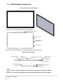
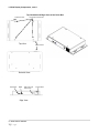
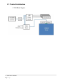
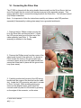
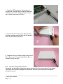
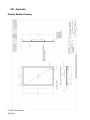
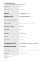
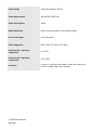
Planar LT3200 Owner Manual LT3200 Owner Manual 1 | P a g e This manual is designed for use with the Planar® LT3200 LookThru™ open frame transparent display. Information in this document has been carefully checked for accuracy; however, no guarantee is given to the correctness of the contents. The information contained in this document is subject to change without notice. This document contains proprietary information that is protected by copyright. All rights are reserved. No part of this document may be reproduced, translated to another language or stored in a retrieval system, or transmitted by any means, electronic, mechanical, photocopying, recording, or otherwise, without prior written permission. Brands or product names are trademarks of their respective holders. LT3200 Owner Manual 2 | P a g e Table of Contents I. PRECAUTIONS ............................................................................................................................ 4 II. LT3200 PRODUCT DESCRIPTION ...........................................................................................5 III. LT3200 DISPLAY COMPONENTS ............................................................................................ 6 IV. PRODUCT ARCHITECTURE .................................................................................................... 8 V. DESIGNING AN ENCLOSURE FOR YOUR LT3200 .............................................................. 9 VI. CONNECTING THE DRIVER BOX ........................................................................................ 10 VII. PRESENTATION OF YOUR MATERIAL USING THE LT3200 ......................................... 13 VIII. APPENDIX ................................................................................................................................... 14 Display Module Drawing 14 Driver Box Drawing 15 Troubleshooting 16 LT3200 Specifications 17 Graphics Input Compatibility 19 Regulatory Summary 19 LT3200 Owner Manual 3 | P a g e I. Precautions and Warnings To maximize the life and safe use of your Planar product, always be sure to follow the warnings and precautions in this product guide. Important Instructions: 1. Read, retain, and heed all warnings and instructions. 2. You must follow all National Electrical Code regulations. In addition, be aware of local codes and ordinances when installing your system. Do: Keep in mind this is an open frame display component. It has components that are fragile and less well-protected than in end-user displays. These vulnerable components are subject to damage from inappropriate handling where contact with abrasive surfaces and sources of electrostatic discharge will damage the unit Design an enclosure to adequately protect the open frame display. Design your display enclosure using the advice given in this manual. Operate and store your transparent display in a clean, dry environment. Disconnect the power plug before cleaning Clean front glass using multiple soft clean cloth moistened with a commercial mild window glass cleaner or isopropyl alcohol (IPA). Remove lint and other loose debris from the inside surface of the LCD with a dry lintfree soft cloth Don’t: Do not look directly at the LED illumination system in operation. Do not touch the front or the inside display surface with sharp or hard objects. Do not use abrasive cleaners, waxes or solvents for your cleaning. Do not spray cleaner inside the display enclosure. We recommend wiping the interior with a soft cloth that has been moistened with a mild detergent. LT3200 Owner Manual 4 | P a g e II. LT3200 Product Description The Planar LT3200 is a high performance open frame transparent display for use indoors in a customer-designed enclosure. Possible digital signage applications include various retail, marketing and other digital showcase uses. The contemporary, bezel-less design and the Planar-modified, high-definition (HD, resolution 1366x768) active matrix liquid crystal display (AMLCD) provide extraordinary, eye-catching transparent display performance with best in class optical clarity, color saturation, contrast and black opacity. The Planar-designed LED illumination system efficiently presents sufficient light intensity to fully illuminate the contents of the transparent display enclosure and AMLCD display simultaneously when a properly prepared enclosure is used. In the LT3200, Planar has provided an open frame display design that enables our customers to create exceptional sales and marketing tools employing the latest in digital display technology. The LT3200 is composed of 2 primary components: the display module and the driver box. The display module is fabricated from 5mm thick, heat-strengthened glass with an antireflection coating on the first surface of the front glass. The front glass is optically bonded to the transparent AMLCD. This optically-bonded assembly is attached to the display chassis along with the LED illumination system and AMLCD drive circuitry. Mounting brackets for the display are also located on the short sides of the frame. The driver box contains the LED controller and the video interface circuitry and can be located remotely from the display module by as much as four feet. Power is supplied to the LT3200 driver box through the four-pin connector of the 48V power supply brick. The power brick is compatible with an input voltage range of 100 to 240VAC with a suitable power cord. Your computer or media player can (either) employ any digital output that interfaces with the LT3200 HDMI or Displayport input plugs. The only additional hardware is the correct interface cable that matches your output plug and one of the LT3200 input plugs. No other special additional hardware is needed. LT3200 Owner Manual 5 | P a g e III. LT3200 Display Components Front and Back Views of the Display Front View ‐ Heat strengthened Glass with AR coating AMLCD Circuit Cover Plate LED Strips (6x) Display Mounting Brackets (2x) Display Chassis Rear View – Display chassis with LED illuminators and mounting brackets Edge Views of the Display AMLCD Assembly Cable Strain Relief Pad AMLCD Circuit Cover Plate Display Mounting Brackets (2x) Display Chassis Front Glass Display Mounting Brackets (2x) ! AMLCD Circuit Cover Plate Display Chassis Front Glass Caution! Avoid any impact or contact with the cover plate surrounding the AMLCD circuit card. It should not be grasped or manipulated while handling the open frame display. LT3200 Owner Manual 6 | P a g e LC3200 Display Components, cont’d Top, Backside and Edge Views of the Driver Box Cable Grommet Driver Box Lid Fasteners Top View Power Switch Backside View DisplayPort HDMI 48V Input from Power Brick Edge View LT3200 Owner Manual 7 | P a g e Power Switch IV. Product Architecture LT3200 Block Diagram LT3200 Owner Manual 8 | P a g e V. Designing an Enclosure for your LT3200 The LT3200 open frame display will provide best in class transparent display performance, but the enclosure design is a critical contributor to the appearance and operation of the full display assembly. We encourage our customers to be creative in designing their presentation configuration using the LT3200. To achieve optimum results, we recommend the following: - Orientation: the display can be used in portrait, landscape or countertop (horizontal) mode. Note that the enclosure can be incorporated into an existing wall or table. - Enclosure material: use materials structurally capable of supporting the weight of the display and its planned contents while providing an opaque enclosed space. Light leaks should be eliminated. - Interior surface finish: it should be a uniform, high reflectance white. Use satin or matte finish white paint or a material with a white reflective body color. A gloss finish is not recommended unless it is part of a specific visual design. Use of a color other than white will reduce the efficiency of the display and will cause a color shift in the output of the AMLCD. Minimize, ideally eliminate, any dark colored surfaces in the interior finish of the enclosure. Note that there is almost no ultraviolet light emitted from the white LEDs employed in the LT3200, but the white light is sufficiently bright to cause potential photobleaching of materials susceptible to light-induced color fading. Use colorfast materials. - Enclosure dimensions: we suggest the horizontal and vertical dimensions be within a few inches of the perimeter dimensions of the front glass (17.9 x 29.9 inches, 455 x 760 mm). The LED lighting system is designed to illuminate a space roughly the rectangular size of the front glass. Items placed in an enclosure much larger than the glass will not necessarily be adequately lit. Regarding the depth of the enclosure, we recommend a depth no greater than about 15 inches (380 mm) for best visibility. You will find items placed closest to the inside surface of the AMLCD will have the best clarity. - Thermal consideration: the display chassis can reach a temperature of 55°C (130°F) during normal operation at typical ambient room temperature (22°C, 72°F) due to heat dissipation from the LED illumination system. Depending on the thermal properties of the enclosure, this can result in enclosure temperatures above 30°C (86°F) that may be detrimental to some items to be demonstrated in the enclosure. While this will not be a problem for the LED illumination system, we recommend a properly ventilated design of the enclosed space if a somewhat elevated enclosure temperature poses an issue to the box contents. Since heat from the LEDs is dissipated primarily through the metal chassis, in designing your enclosure make certain to not hinder air flow in the vicinity of the chassis. No fan should be needed. - Environment: the LT3200 display is intended to be used indoors at a typical indoor temperature range (10° to 30°C, although the operating range is 0° to 40°C). Positioning the display in direct sunlight or other very bright illumination sources is not recommended for best viewing performance. Do not use the LT3200 in an environment of condensing humidity. - Placement of the Driver Box: We have provided sufficient length in the wiring bundle for the driver box to be as much as four feet from the display module. Be certain to protect and enclose the wire bundle and any other wiring, including the power brick, from customer access. Note that the LT3200 power switch is located in the Driver Box so be sure to provide access. - Power Supply: the power brick is compatible with 100 to 240V input. - The system is shipped from the factory with the LED power leads and the video cable disconnected from the driver box. These must be attached before operating the display. In addition, there are grounding wires in the LED and video wiring bundle that are to be connected to the driver box. More details are found in the next section of this document. - The LT3200 is a component type open frame TFT LCD display intended to be installed into a final system assembly. Therefore the mechanical enclosure, electrical enclosure, EMC enclosure and mounting function must be evaluated in the final system assembly. LT3200 Owner Manual 9 | P a g e VI. Connecting the Driver Box The LT3200 is shipped with the wiring bundle disconnected from the Driver Box so the free end of the bundle can be routed in the enclosure as part of the assembly process. This section describes how to connect the wiring bundle to the Driver Box. You will need a small (#1) Phillips screwdriver. Note: It is important to follow the instructions carefully and observe safe ESD practices, especially if the assembly is taking place away from a grounded workbench. 1- Remove the four Philips screws securing the lid to the Driver Box and remove the lid. Locate the LED ground wire loop at the free end of the cable assembly (see Photo 1). The cable assembly is attached to the display. 2- Remove the Phillips screw from the corner of the video board closest to the cable slot. As shown in Photo 2 place the screw in the ground wire loop connector (upper arrow) from the cable bundle and secure the screw back in place with the ground wire loop (lower arrow). 3- Carefully position the free end of the LED wiring bundle near the corner of the box that has the cable slot. Locate the LED connector and orient it as seen in Photo 3 at right. While avoiding placing any stress on the attached wires, gently insert the connector and fully seat it in the socket by pressing on the edges of the connector, not the wires. LT3200 Owner Manual 10 | P a g e 4- Locate the video connector in cable assembly as shown in photo 4 at right. 5- Orient the video plug as seen in Photo 5A. Insert the edge into its socket on the video board. Align the connector parallel to the socket and gently slide the connector into the socket (Photo 5B). Using steady pressure between thumb and fingernail of index finger, seat the connector. A properly inserted connector will have the backside of the connector located parallel to the socket. The white arrows (Photo 5C) point out the slots in the socket that should be fully filled with the white color of the connector. 6- Place the video ground clasp around the bare-metal section of the video cable and attach it to the standoff near the LED connector on the LED driver board. See photo 6 at right. LT3200 Owner Manual 11 | P a g e 7- Once the LED connector, the two ground connections, and the video connector have been attached, position the rubber grommet into the slot in the box as shown in Photo 7. 8- Position the lid over the lower half of the box as shown, making sure the tab in the lid (arrow in Photo 8) captures the grommet. 9- Refasten the four Phillips screws to secure the Driver Box cover. The assembled Driver Box is shown in Photo 9 at right. Note: once the wiring bundle has been connected, the protective release liner can be removed from the front surface of the display. The power brick should be plugged into the driver box and a grounded power receptacle during the removal. LT3200 Owner Manual 12 | P a g e VII. Presentation of Your Material using the LT3200 You should experiment with placement of the objects to be displayed in the LT3200 to optimize their appearance and interaction with your video content. You will find that the brightness of display box and the legibility of the screen content can be affected by the color of objects placed in the display box. For best results we suggest avoiding large areas of dark colors inside the display box. Most conventional digital signage video content can be used with the LT3200, but enhancements to the content are possible to optimize the attention-grabbing effect you and your customers will see in using the Planar transparent display. In preparing video content for the LT3200 driving the LCD to white will produce the highest transparency while black screen features will result in the most opacity. Intermediate colors will have intermediate transparency. Note that slide-show presentation software, such a Microsoft Powerpoint™, can be used to create simple but effective content for the LT3200. In order to maximize the brightness of the LT3200 we have provided an extremely high level of white light illumination for your display box design. In addition to enhancing the appearance of objects inside the box and of the LCD display, this intense light level can be used to drive a photovoltaic turntable to further enhance the eye-catching performance of your Planar transparent display box by rotating your interior content. These light-driven turntables are available online: search using the keywords: “solar turntable”. Most of these turntables have a limited weight capacity. We recommend testing of materials to be displayed for an extended period (weeks to months) in the display box for their color stability. The intense white light illumination required inside the box can cause color fading due to photobleaching, similar to what can happen to vulnerable colored materials due to exposure to sunlight. LT3200 Owner Manual 13 | P a g e VIII. Appendix Display Module Drawing LT3200 Owner Manual 14 | Page Driver Box Drawing LT3200 Owner Manual 15 | Page Troubleshooting A properly-functioning LT3200 will show a “splash screen” when power is first applied. If a suitable video source is attached, the screen will then display whatever video image is being sent to the LT3200 shortly after the splash screen appears. Note that when power is applied you should also see light from the LEDs located around the perimeter of the AMLCD screen. When power is being supplied to the LT3200 power supply, the indicator light on the power brick will glow. Possible Problem – After setup, the switch on the Driver Box has been turned on and no image appears. In addition, the LEDs in the box are not functioning. This probably means no power is being applied to the display box. ‐ Items to check: Make sure the power switch is in the on position. Verify the power brick is plugged into a power source. Note: if the power brick is receiving power, an LED on the brick will be lit. Make sure the power cord is securely attached to the power brick. Check to see the output plug from the power brick is properly inserted in the plug located in the Driver Box. Possible Problem – The splash screen appears after power is turned on, but a “no sync” message appears on the screen and afterward the monitor shows no image. This usually means no recognizable video signal is being received by the display box. ‐ Items to check: Make sure the video cable is properly plugged in at the video source (computer or media player). Verify the other end of the same video cable checked previously is securely plugged into either the HDMI or DisplayPort receptacle in the Driver Box If an adapter is being used as part of the video cable, check to confirm the two plugs are properly seated. If you are using a DVI plug from the video source, check to make sure there are no bent pins in the plug. Verify that the output of your computer or player is one of the formats listed on page 19 of this document. If signal is from a laptop, verify from the computer settings panel that the display is active. Make sure your video source is turned on and the output software is running (may require a second, known good monitor). If these troubleshooting instructions do not resolve the problem, please contact Planar Support at www.planar.com/supportat or call 1 866 PLANAR1 and select option 1 to determine the next steps. LT3200 Owner Manual 16 | Page LT3200 Specifications This section contains specifications for the LT3200 display. Product Name LT3200 Planar Part Number 997‐6868‐00 Viewable Size 31.25" diagonal (27.3” x 15.2”) Viewing Angle (Typical) 178° Horizontal and Vertical Response Time (G‐to‐G, Typical) 8 msec Brightness (Typical) Dependant on customer enclosure design Native Display Resolution 1366 x 768 Aspect Ratio 16:9 Color Palette 16.7 million colors Pixel Pitch 0.511 mm Refresh Rate 50 to 60 Hz Exterior Dimensions (W x H x D) 29.9” (760 mm) x 17.9” (455 mm) x 2.1” (53.3 mm) Module Weight, less Driver Box 12.2 lbs (5.55 kg) Driver Box Dimensions 9.19” (233 mm) x 7.50” (191 mm) x 1.38” ( 35.1mm) Video Inputs Digital (HDMI, DisplayPort) LT3200 Owner Manual 17 | Page Power Supply External AC adapter, 48V DC Power Requirements 100‐240 VAC (50/60 Hz) Power Consumption 125W Module Mounting Built‐in mounting bracket, see outline drawing Service and Support 3‐Year Warranty Product Approvals NRTL Listed, FCC‐Class A, CE, RoHS Environmental ‐ Operating Temperature 0° to 40°C Environmental ‐ Operating Temperature ‐10° to 50°C In the Box LT3200 32" LookThru LCD module, Driver Box, Power Brick and Cord, HDMI Cable, User’s Manual LT3200 Owner Manual 18 | Page Graphics Input Compatibility The LCD monitor has been tested to synchronize to, and scale the following digital signal graphics inputs and generate a stable display that has a similar geometry. Mode Resolution V‐Frequency (Hz) VGA 640 x 480 60 WVGA 800 x 480 60 SVGA 800 x 600 60 XGA 1024 x 768 60 WXGA 1280 x 720 60 WXGA 1280 x 768 60 HD 1366 x 768 60 Regulatory Compliance FCC Radio Frequency Interference Statement This equipment has been tested and found to comply with the limits for a Class A digital device pursuant to Part 15 of the FCC Rules. These limits are designed to provide reasonable protection against harmful interference with the equipment is operated in a commercial environment. This equipment generates, uses and can radiate radio frequency energy and, if not installed and used in accordance with the instruction manual, may cause harmful interference to radio communications. Operation of this equipment in a residential area is likely to cause harmful interference in which case the user will be required to correct the interference at their own expense. Planar Systems, Inc. Customer Service 24x7 Online Technical Support: http://www.planar.com/support Support Tel: 1-866-PLANAR1 (866-752-6271) or +1 503-748-1100 Hours: M-F, 8am - 8pm Eastern Time | M-F, 5am - 5pm Pacific Time © 2013 Planar Systems, Inc. Planar is a registered trademark of Planar Systems, Inc. Other brands and names are the property of their respective owners. Technical information in this document is subject to change without notice. 020-1210-00C LT3200 Owner Manual 19 | Page