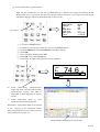
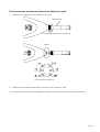
1
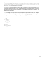
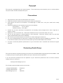
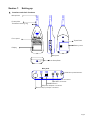
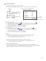
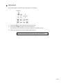
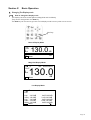
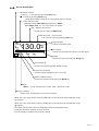
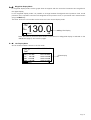
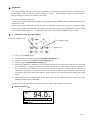
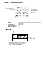
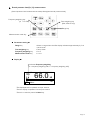
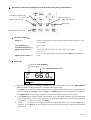
TYPE 6226
Integrating Sound Level Meter
Instruction Manual
(Version 1.5PA)
www.castlegroup.co.uk
Thank you for buying a Castle product, I am sure you will find both the goods and the service to
be of the highest quality but if not, then please feel free to write to me personally and I will
ensure that your needs are dealt with immediately.
This manual is designed to show you the operation of the goods you have purchased and a very
brief insight into acoustics itself. If you would like to become a competent person in the eyes of
the law, then you may like to know more about our Competent Persons training course for the
Noise at Work Regulations.
It is my intention for Castle Group Ltd to provide a complete range of Noise and Vibration
products and Services of the highest standard. If you would like to know more about any of our
other products and services then please telephone on +44(0)1723 584250.
Simon Bull
Managing Director
Page 1
Copyright
This manual is copyrighted with all rights reserved. The manual may not be copied in part or in whole without
the prior written consent of Castle Group Ltd.
Precautions
•
•
•
•
•
•
•
•
•
•
Only operate the instrument as described in this manual.
These are precision instruments, protect from shocks and vibrations.
Take special care with the microphone. The diaphragm is made from a very thin metal and is easily
damaged.
Ambient conditions for the operation of the unit are as follows:Temperature
0°C to +50°C
Relative Humidity 25 to 90%
Protect the unit from extremes of temperature and humidity, direct sunlight and air with a high salt or
sulphur content.
Always turn the unit off after use. Remove the batteries from the instrument when not in use.
Do not use any solvents or cleaning agents on the instrument. Use only a soft dry cloth or a soft cloth
lightly moistened with water when necessary.
Do not let any conductive objects, such as wire or metal scraps get into the unit.
Do not try to disassemble the instrument or attempt any repairs as this will invalidate your warranty. Take
a note of the condition of the instrument and contact your authorised Castle service station.
To ensure continued precision performance of your instrument have it checked and serviced at regular
intervals.
Contacting Castle Group
This manual contains complete operating instructions for the Castle 6226 Integrating Sound Level Meter, read
it carefully and you will quickly become familiar with your instrument and its operation.
If you do encounter problems with the operation of your instrument please feel free to contact customer
support with your enquiry on: [email protected]
For all other enquires please contact us on either: +44 (0)1723 584250
+44 (0)1723 583728
www.castlegroup.co.uk
Telephone
Fax
Web Site
Page 2
Introduction
1.Overview
The Castle 6226 (Class 2) Integrating Sound Level Meter is ideally equipped for carrying out Noise at
Work Risk Assessments, as well as the majority of environmental survey work. The range of parameters
measured, the wide measuring capability of the meter and the ease of use, mean that this equipment is
suitable for anything from aircraft noise to lawnmower design, and from construction sites to laboratories.
The Castle 6226 has an easy to follow menu system and clearly marked keys, all designed to make the
meter simple-to-use. The back-lit LCD display is also very clear with large figures and a quasi-analogue
display bar to show the changes in sound level as they happen.
2.Features
•
•
•
•
•
Equivalent continuous level (Leq)
5 user selectable percentile values (Ln)
Wide Linearity range of 90dB
RS232 for data output to optional software
Memory storage for 10,000 data-points
3.Configuration
(1) Integrating Sound Level Meter
(2) 1/2”electret condenser microphone
(3) Windshield (∅50)
(4) Screwdriver
(5) Wrist strap
(6) Carrying case
(7) Instruction manual
(8) Optional extras
• AC adaptor
• Extension cable(2m, 5M. 10m)
• Interface cable
• Output cable(BNC pin cord)(2m)
• Data management software
(with Interface Cablel)
TYPE 6226
TYPE 7052N
1
1
1
1
1
1
1
PSU4
ZL0046-02, 05, 10
ZL0026
ZL0071
PC0226-4
Page 3
Contents
Section 1
1.
2.
3.
4.
5.
6.
Locations and their functions....................................................................................................5
Battery installation..........................................................................................................................6
AC power adaptor ............................................................................................................................6
LCD adjustment.................................................................................................................................7
Calendar adjustment ......................................................................................................................8
LCD backlight ......................................................................................................................................9
Section 2
1.
2.
3.
Setting up
Basic Operation
Changing Display mode ............................................................................................................. 10
Operation of panel switches and their function .......................................................... 13
Calibration ........................................................................................................................................ 14
Section 3
Measuring Procedure
1. A-weighted sound pressure level (LA) measurement................................................ 16
2. Sound pressure level (LC/Lf) measurement .................................................................. 17
3. Equivalent continuous A-weighted sound pressure level (LAeq)
measurement ............................................................................................................................... 18
4. Single event sound exposure level (LAe) and
Percentile level (Lx) measurement................................................................................... 19
5. Max Hold Measurement ........................................................................................................... 20
6. C-weighted waveform peak hold measurement (LCPeak) ......................................... 21
Section 4
Menu
1. How to use Menu.......................................................................................................................... 22
2. Menu (1/2)...................................................................................................................................... 23
3. Mode Set (2/2) ............................................................................................................................. 24
Section 5
1.
2.
AC, DC Output
AC Output ......................................................................................................................................... 25
DC Output ......................................................................................................................................... 25
Section 6
Printing .............................................................................................................. 26
Section 7
Data Transfer to a Personal Computer.................... 27
Section 8
Specifications ............................................................................................ 29
Pin Connections and How to Connect the Extension cable.................................... 30
Page 4
Section 1
Setting up
1.Locations and their functions
Microphone
Preamplifier
Threaded retaining ring
Front panel
Tripod Bush
Battery cover
Display
Side panel
Wrist Strap Bush
Side panel
Calibration potentiometer
AC OUT connector
DC OUT connector
POWER switch
AC power adaptor connector
External Input/Output connector
Page 5
2.Battery installation
When the display indicates low battery, install new batteries.
For long-term measurement, install new batteries in advance.
The following diagrams indicate the battery condition.
Full
Low
Replace batteries.
To install new batteries:
1)Turn off the POWER switch.
2)Push the Battery cover gently where it says ‘OPEN’ and slide it to the right.
3)Insert the new batteries according to the diagram inside the battery compartment and replace the
cover.
CAUTION
Place each individual battery with the positive terminal to the
positive markings on the case. All four batteries should be
replaced at the same time.
・Battery life is approximately:
20 hours (Alkaline batteries, continuous operation)
10 hours (Manganese batteries, continuous operation)
・Use of the LCD backlight shortens the life of the batteries (approximately 1/3).
3.AC power adaptor
1)Turn off the POWER switch.
2)Connect the optional AC power adaptor to the AC power adaptor connector.
3)Place the AC plug in the AC 240V outlet.
CAUTION
The use of an AC power adaptor other than the one
recommended may cause damage to the instrument.
AC power adaptor connector
Page 6
4.LCD adjustment
The LCD contrast can be adjusted when the batteries are low or when new batteries are installed.
The procedure is as follows.
Menu key
Cursor key
Set key
View key
1) When you press the Menu key,
<menu>
Meas Mode
Interval
I/O
Data delet
LCD cont
date y/m/d
time
the following screen appears.
1/2
: Manu
: Single
: OFF
: OFF
: *****
: 00/01/01
: 00:00:00
2)Select LCD cont with Cursor key
, then move the cursor to the right with
key.
3)Adjust the LCD contrast with
key, then press Set key to save the setting.
Asterisks indicate the degree of contrast.
After pressing Set key, the cursor moves to the left.
4)To go back to measurement mode, press the View key.
Page 7
5.Calendar adjustment
To adjust the calendar (time), operate as follows.
The calendar can be adjusted in the Menu mode in the same way as the LCD adjustment.
Menu key
1)When you press the Menu key, the
following screen appears.
<menu>
1/2
Cursor key
Meas Mode
: Manu
Set key
Interval
: Single
I/O
: OFF
Data delet
: OFF
View key
LCD cont
: *****
date y/m/d
: 00/01/01
time
:00:00:00
Date
adjustment
Time adjustment
【Calendar adjustment】
1)Select date y/m/d with Cursor key
, then move the cursor to the right with
key.
2)Set the year/month/day with
key, then press Set key to save the setting.
After pressing Set key, the cursor moves to the left.
3)To return to the measurement mode, press View key.
【Time adjustment】
1)Select time with Cursor key
, then move the cursor to the right with
key.
2)Set the hour:minute:second with
key, then press Set key to save the setting.
After pressing Set key, the cursor moves to the left.
3)To return to the measurement mode, press View key.
【Caution】
Be sure to enter the date (date y/m/d) in the order of “year month day.”
Input any figure of; y(year): 00 – 99, m(month): 01 – 12, and d(day): 01 – 31.
e.g.: - For November 30, 2003 input 03/11/30
Be sure to enter the time in the order of “hour minute second.”
Input any figure of; h(hour): 00 – 24, m(minute): 00 – 59, s(sec0ond) 00 – 59.
e.g.: - For 23:58:32 input 23/58/32
<Entry of incorrect date and time>
The instrument has a function for outputting measured data to a personal computer.
During transfer of data, if an incorrect date and time are entered, an error message “Econver
Error” is displayed on the screen and data transfer cannot be carried out.
Page 8
6.LCD backlight
Your Castle 6226 is equipped with a backlight on the display.
Light key
1)Press the Light key and the LCD backlight illuminates.
2)Pressing the Light key again turns the backlight off.
The backlight automatically turns off after approximately 30 seconds.
3)When the batteries are low the LCD backlight will dim.
CAUTION
Use of the LCD backlight shortens the life of the batteries.
Page 9
Section 2
Basic Operation
1.Changing The Display mode
1-1 How to change the display mode
The display has three modes (Normal, Magnified and List Mode).
They can be changed with the View key.
The View key can be used to go back to this display mode from any other menu screen.
View key
Normal Display Mode
130.0
00h
FAST
LA
40
000h00m00s
Manu
dB
130
Magnified Display Mode
000h00m00s
130.0
FAST
LA
00h
E
dB
Manu
List Display Mode
FAST
E
Lap : 140.0dB
Laeq : 140.0dB
Lae : 140.0dB
LMin : 140.0dB
LMax : 140.0dB
Manu
00h
000h00m00s
La05:140.0dB
La10:140.0dB
La50:140.0dB
La90:140.0dB
La95:140.0dB
dB
Page 10
1-2
Normal Display Mode
:Operation indicator
blinking:in operation (by pressing Start key)
■:Pause (by pressing Pause key).
When Data deletion mode is set, this symbol does not appear.
E:Data deletion mode
E appears when Data delet was selected in Menu.
When Meas Time is 1, 3 or 5s, E does not appear.
00h:Measurement time:
Shows the time set with Meas Time.
000h 00m 00s:Time counter
This counter starts by pressing Start key.
E
FAST
LA
40
00h
000h00m00s
130.0
Manu
Un
Ov
Digital display:
Shows the present value.
dB
130
Bar display
Shows the instantaneous value on the bar graph.
Range:
Shows the range selected with Range key.
Time weighting:
Shows time weighting (FAST, SLOW or Imp).
Frequency weighting:
Shows frequency weighting (A, C, or FLAT).
Mode of Measurement
Shows the selected mode (Leq) with Mode key.
Mode:
Manu:normal measurement mode Cal:calibration mode
Battery condition:
Shows a four level display of the battery condition.
・When the input signal level is lower (-0.6dB) than the limited scale of the selected range,
Un appears.
・When the input signal level is higher (+3dB) than the limited scale of the selected range,
Ov aqqears.
・The digital display shows the time-weighted or frequency-weighted value.
・The digital display is updated once per second.
・The bar display is updated 10 times per second.
Page 11
1-3 Magnified Display Mode
In magnified display mode, the bar graph does not appear and the numerical characters are magnified in
the digital display.
In the magnified display mode it is possible to change between A-weighted sound pressure level, sound
pressure level, equivalent continuous A-weighted sound pressure level, or percentile level measurement
using the Mode key.
The other functions in this mode are the same as in the normal display mode.
130.0
E
FAST
LA
00h
000h00m00s
Magnified display
dB
Manu
Note: The value of percentile level shown on the Normal or Magnified display is selected on the
<Mode Set> page 2/2 of <menu> pages.
1-4 List Display Mode
All the measured data is shown in the list mode.
E
FAST
Lap : 140.0dB
Laeq : 140.0dB
Lae : 140.0dB
LMin : 140.0dB
LMax : 140.0dB
Manu
00h
000h00m00s
La05:140.0dB
La10:140.0dB
La50:140.0dB
La90:140.0dB
La95:140.0dB
Data display
dB
Page 12
2.Operation of panel switches and their function
Cursor key
•
Light
•
Menu
•
Set
•
•
Cursor key
Cal
•
Meas. Time
•
A • C • Flat
•
F • S • Imp
•
Range
•
Mode
•
Pause
•
View
•
Start Stop
:LCD backlight key
See “LCD adjustment”.
:Menu key
See “Menu“.
:Set key
Saves the settings of the menu screen or resets Max Hold value.
:is used to move a cursor to select an item.
:Calibration key
See “Calibration“.
:Measurement time selection key
See “Measurement Procedure”.
: Frequency Weighting Key
See “Measurement Procedure”.
: Time Weighting Key
See “Measurement Procedure”.
:Range selection key
See “Measurement Procedure”.
:Mode selection key
See “Measurement Procedure”.
:Pause key
See “Measurement Procedure”.
:Display mode key
See “Changing Display mode”.
:Start and Stop key
See “Measurement Procedure”.
Page 13
3.Calibration
It is recommended that the instrument’s calibration is checked and adjusted where necessary with a
Castle GA601, Class 2 calibrator before readings are taken. The calibration should be re-checked after
taking readings to confirm the validity of the results.
There are two types of calibration:
1) Using the recommended Castle GA601, which supplies typically 94dB (relative to 20µPa pressure) at a
frequency of 1kHz.
2) Using the internal calibration mode. The internal calibration should only be used as a general system
check e.g. for a broken or damaged microphone or for electrical calibration by a calibration house, it should
not be used for field calibration. To maintain Class 2 accuracy the Castle GA601 must be used.
3-1
Calibration using the Castle GA601
Frequency weighting key
Time weighting key
Range key
1)Turn on the POWER switch.
2) Set the frequency weighting to A with Frequency weighting key.
3) Set the time weighting to Fast with Time weighting key.
4) Set the range to 30~120dB with Range key.
5) Ensure the calibrator is attached to the microphone by gently inserting the microphone into the cavity
of the calibrator. A certain amount of resistance should be felt whilst inserting the microphone as
the o-ring seal on the calibrator forms a seal around the microphone. Ensure that the calibrator is
switched on and set to the chosen level and all correction factors for atmospheric pressure and
microphone type have been accounted for, please refer to your Castle Calibrator Manual for more
detail.
6) Adjust the calibration potentiometer on the side panel until the display shows the output level of the
GA601 (standard value is 94.0dB).
Please note that the calibrator automatically turns OFF after approximately one minute.
< Calibration display >
FAST
E
LA
30
Manu
94.0
00h
000h00m00s
dB
120
Page 14
3-2 Calibration using internal calibration mode
The instrument can be calibrated using the internal generator (1kHz, sine wave)
Cal key
Range key
1)Turn on the POWER switch.
2)Press the Cal key.
3)Press the Range key, and choose ‘100dB’ using the cursor keys
and press the Range key
again to confirm.
4)Adjust the calibration potentiometer on the side panel until the display shows 94dB.
5)Press the Cal key once again to complete the calibration.
< Calibration display >
FAST
E
LA
20
00h
000h00m00s
94.0
Cal
dB
100
By switching the Rang key,
the figure of 100 blinks.
< Side panel >
Calibration potentiometer
< Reference>
Full scale range and Cal (the display shows)
Full scale Range
(dB)
80
90
100
110
120
130
OUTPUT VOLTAGE(V)
CAL
(dB)
AC OUT
DC OUT
74.0
84.0
94.0
104.0
114.0
124.0
0.500
0.500
0.500
0.500
0.500
0.500
2,350
2,350
2,350
2,350
2,350
2,350
<Reference> Relation between the display value of each range, and output voltage
40~130
130
120
110
100
90
80
70
60
50
40
30~120
120
110
100
90
80
70
60
50
40
30
DISPLAY VALUE(dB)
RANGE
20~110
20~100
110
100
100
90
90
80
80
70
70
60
60
50
50
40
40
30
30
20
20
-
OUTPUT VOLTAGE(V)
20~90
90
80
70
60
50
40
30
20
-
-
20~80
80
70
60
50
40
30
20
-
-
-
AC OUT
DC OUT
1.00000
0.31623
0.10000
0.03162
0.01000
0.00316
0.00100
0.00032
0.00010
0.00003
2.50000
2.25000
2.00000
1.75000
1.50000
1.25000
1.00000
0.75000
0.50000
0.25000
Page 15
Section 3
Measuring Procedure
1. A-weighted sound pressure level (LA) measurement
Frequency weighting key
(A, C or Flat)
Time weighting key
(Fast, Slow or Imp)
Range key
Measurement mode key
< Parameter setting >
Range key
Time weighting key
Frequency weighting key
Measurement mode key
:Select a range where the Bar display indicates approximately 2/3 of
the full scale.
:Fast or Slow
:A
:LA
< Display >
Indicates Time weighting.
(Fast or Slow)
E
FAST
LA
30
Manu
00h
000h00m00s
66.0
dB
120
Digital display
Bar display
・The displayed LA level is updated once per second.
・The bar display is updated 10 times per second.
・There is no need to press the Start key.
Page 16
2.Sound pressure level (LC/Lf) measurement
(Sound pressure level measurements except A-weighted sound pressure level.)
Frequency weighting key
(A, C or Flat)
Time weighting key
(Fast, Slow or Imp)
Range key
Measurement mode key
< Parameter setting >
Range key
Time weighting key
Frequency weighting key
Measurement mode key
:Select a range where the Bar display indicates approximately 2/3 of
the full scale.
:Fast or Slow
:C or F
:LC or Lf
< Display >
Indicates Frequency weighting.
(LC : frequency weighting is C ; Lf : frequency weighting is F.)
FAST
E
LC
30
66.0
00h
000h00m00s
dB
Manu
120
・The displayed level is updated once per second.
・The bar display is updated 10 times per second.
・There is no need to press the Start key.
Page 17
3.Equivalent continuous A-weighted sound pressure level (LAeq) measurement
Frequency weighting key
(A , C or Flat)
Measurement time
Time weighting key
(Fast, Slow or Imp)
Range key
Measurement mode key
< Parameter setting >
Range key
Time weighting key
Frequency weighting key
Measurement time key
Measurement mode key
:Select a range where the Bar display indicates approximately 2/3 of
the full scale.
:Fast or Slow
:A
:1s, 3s, 5s, 10s, 1m, 5m, 10m, 15m, 30m, 1h, 8h, 24h
and ***.
(***: the measurement continues until the Stop key is pressed.)
:LAeq
< Display >
Indicates Time weighting.
(Fast or Slow)
Indicates Measurement time.
66.0
00h
FAST
LA
30
Manu
000h00m00s
dB
120
•
Measurement starts by pressing the Start key, and automatically stops at the Measurement
time. The digital display indicates the calculated data at that time.
If the Stop key is pressed during measurement, the digital display indicates the calculated data at
that time. When the Interval is set to repeat in the Menu display, the measurement is repeated in
every Meas Time. (This function is useful for printouts and data transfer to a computer.)
• If the Pause key is pressed during measurement, then the display indicates the calculated data
from the start point to the current time less 3 or 5 seconds, whichever is selected for ‘Data delet’
in the Menu. To set this function, See Menu.
• When * * * is selected, the display indicates the calculated data at the time the Stop key is
pressed. If the Stop key is not pressed, the measurement continues for 199 hours 59 minutes
59 seconds.
Page 18
4.Single event sound exposure level (LAe) and Percentile level (Lx) measurement
When measuring LAeq or LAe, the following automatically starts by pressing the Start key.
•
•
•
Equivalent continuous A-weighted sound pressure level
Single event sound exposure level
Percentile level
:L05 , L10 , L50 , L90 , L95 ,
:LAeq
:LAe
Lmin or Lmax
LAeq can be displayed in Normal display mode, but LAe or Lx are displayed only in List display
mode.
E
FAST
Lap : 140.0dB
Laeq : 140.0dB
Lae : 140.0dB
LMin : 140.0dB
LMax : 140.0dB
Manu
00h
000h00m00s
La05:140.0dB
La10:140.0dB
La50:140.0dB
La90:140.0dB
La95:140.0dB
dB
Page 19
5.Max Hold Measurement
Set key
Measurement mode key
< Parameter settings >
Measurement mode key
: MH
< Display >
Indicates Measurement mode
E
FAST
LAMH
30
•
•
•
Manu
66.0
00h
000h00m00s
dB
Digital display
Bar display
120
After pressing the Set key, the digital display holds its maximum value and is only updated
when a new maximum value is measured.
Pressing the Set key resets the MH value.
The bar display does not hold its value, but shows an instantaneous value updated every 0.1
seconds.
Page 20
6. C-weighted waveform peak hold measurement (LCPeak)
Lcpeak is measured on “Peak measurement” setting.
Change the basic setting from Manu (default) to Peak.
(1) Press Menu key once to call <Menu>1/2 screen and check the cursor is on the top line of
“Meas Mode”.
(2) Move to the right column with
key.
(3) Change “Manu” to “Peak” with
key and press the SET key to enter.
(4) Return to the normal display from <Menu> screen by pressing the View key and check the
display shows Peak under the figures.
< Parameter setting >
Range key:
Select a range that Bar display indicates approximately 2/3 of the full scale.
Time weighting key:
N/A
Frequency weighting key:
C
Measurement time key:
1s, 3s, 5s, 10s, 1m, 5m, 10m, 15m, 30m, 1h, 8h, 24h,
and ***.
(***: Measurement continues until Stop key is pressed.)
Measurement mode key:
N/A (fixed to LCpk )
< Display >
<Mode Set> screen (for example)
<menu>
Meas Mode
Interval
I/O
Data delet
LCD cont
date y/m/d
time
1/2
: Peak
: Single
: Off
: Off
: ****
: 02/04/19
: 11: 16: 58
e
Normal display mode screen
Indicates Measurement time
FAST
By pressing Measurement
mode key, toggles:
A→C→F→A→…
•
•
•
LCpk
30
86.0
00h
Peak
000h00m00s
dB
120
Measurement starts by pressing the Start key and automatically stops in the measurement time
(Æ is displayed during measurement). The display indicates the calculated data at that time.
If the Stop key is pressed during measurement, the display indicates the calculated data at that
time.
When *** is selected, the display indicates the calculated data at the time the Stop key is pressed.
If the Stop key is not pressed, the measurement continues for 199 hours 59 minutes 59 seconds.
Page 21
Section 4
Menu
1.How to use Menu
To open the Menu display press the Menu key.
Return to the measurement display by pressing the View key.
Menu key
Set key
Cursor key
Every time the Menu key is pressed, <menu> and <Mode Set> pages are alternated.
Select an item with
key and complete the selection with
key, then change the
parameters with
key.
<menu>
Meas Mode
Interval
I/O
Data delet
LCD cont
date y/m/d
time
<Mode Set>
Range
Dyn cher
Freq corr
Meas time
View
baud rate
1/2
: Manu
: Single
: OFF
: OFF
: *****
: 00/01/01
: 00:00:00
2/2
Basic setting for Calendar,
LCD contrast etc.
Setting for measurement modes.
: 130dB
: FAST
:A
: 1s
: L05
: 9600
Page 22
2.Menu (1/2)
<menu>
Meas Mode
Interval
I/O
Data delet
LCD cont
date y/m/d
time
•
Items
Meas Mode
•
Interval
•
I/O
•
Data delet
•
LCD cont
•
date y/m/d
•
time
1/2
Page of Menu
: Manu
: Single
: OFF
: OFF
: *****
: 00/01/01
: 00:00:00
Initial value
: Manu
Explanation
:Measurement mode
Manu : Normal measurement mode
: Single
:Measuring interval
OFF :Continuous data output mode.
Single :Completes one measurement in Meas Time
by pressing Start key.
Repeat:Repeats measurement in every Meas Time
by pressing Start key.
Measurement is repeated until Stop key is
pressed.
: OFF
:External equipment connection setting
OFF :No external equipment.
Print :Enables an external printer to be used.
PC
:Enables a personal computer to be used.
: OFF
:Data deletion mode setting
OFF :No Data deletion mode
3sec :deletes preceding 3 sec. data
when Pause key is pressed.
5sec :deletes preceding 5 sec. data
when Pause key is pressed.
When Meas Time is 1, 3 or 5s, this function does not work.
: ****
:LCD contrast adjustment.
See “LCD adjustment”.
: 00/01/01 :Calendar setting (indicates year/month/day)
See “Calendar adjustment”.
: 00:00:00 :Time setting
See “Calendar adjustment”.
Page 23
3.Mode Set (2/2)
<Mode Set>
Range
Dyn char
Freq corr
Meas time
View
baud rate
•
•
Range
Dyn char
: 130dB
: FAST
2/2
: 130dB
: FAST
:A
: 1s
: L05
: 9600
:Shows a range value set with the Range key.
:FAST , SLOW or Imp
Shows Time weighting set with the F ・S ・Imp key.
•
Freq corr
:A
:Shows Frequency weighting set with the A ・C ・Flat key.
•
•
Meas time
View
: 1s
: L05
•
baud rate
: 9600
:Shows Measurement time set with the Meas time key.
:Mode setting in Normal and Magnified display mode.
Sets the value displayed in Normal and Magnified screen.
:Baud rate setting
4800, 9600 or 19200.
•
•
The contents are updated every time the settings are changed.
The Range etc. can be changed in this menu.
.
Page 24
Section 5
AC, DC Output
1.AC Output
The AC Output is the frequency-weighted signal.
Output: 1Vrms (Full Scale), Output impedance: 600Ω, Load impedance > 10kΩ
2.DC Output
The DC Output is a frequency weighted, root mean squared, and then logarithmically converted signal.
Output: 2.5V (Full Scale), 0.25V/10dB, Output impedance: 50Ω, Load impedance > 10kΩ
Page 25
Section 6
Printing
After measurement is completed, the results can be printed with an optional printer.
(Results can not be printed during measurement.)
<menu>
Meas Mode
Interval
I/O
Data delet
LCD cont
date y/m/d
time
1/2
: Manu
: Single
: OFF
: OFF
: *****
: 00/01/01
: 00:00:00
The procedure is as follows.
1) Turn off the POWER switch.
2) Connect to a printer and turn on the POWER switch. The version is automatically printed when
powered on.
3) Ensure the Baud Rate is set the same on the 6226 as the printer (See section 4, No 3. Mode
Set 2/2 on page 24). See separate Printer manual for setting the baud rate of the printer.
4) Select I/O in Menu display.
5) Select Print, then press the Set key.
The display shows as follows:
Print
Start/Stop key
6) All data is printed by pressing the Start key.
Printing is stopped by pressing the Stop key.
7) After completion of the data transfer to a printer, the display returns to
Menu automatically.
<Printout form>
Example
00/01/05 2:15:16 F 130dB
000h00m10s
Laeq:130.0 La05:130.0
Lae :130.0 La10:130.0
La50:130.0
LMin:130.0 La90:130.0
LMax:130.0 La95:130.0
Explanation
Starting date and time, Time weighting and Range
Measurement time
data
〃
〃
〃
〃
Starting date and time, Time weighting and Range are printed on the first line.
Measurement time is printed on the second line.
Data is printed on the third to seventh line.
When the Interval is set to Repeat in the Menu display, the results of every MeasTime are printed in
the above form.
Measurement is stopped by pressing the Stop key, data is printed as ***.
Page 26
Section 7
Data Transfer to a Personal Computer
After or during measurement, the data can be transferred to a personal computer.
1) Data transfer after measurement
<menu>
Meas Mode
Interval
I/O
Data delet
LCD cont
date y/m/d
Time
Press Menu
1/2
:Manu
:Repeat
:PC
:Off
:****
:00/11/20
:11:30:26
The procedure is as follows.
8) Turn off the POWER switch.
9) Connect to a PC using the cable and turn on the POWER switch.
10) Press the Menu key and select I/O in the Menu display.
11) Select PC, then press the Set key.
The display shows as follows:
PC
Start/Stop key
12) All data is transferred by pressing the Start key.
Data transfer is stopped by pressing the Stop key.
6)After completion of the data transfer, the display returns to
Menu automatically.
The data is saved in .csv format so it can be opened directly with spreadsheet software e.g.
Microsoft Excel.
Page 27
2)
Data transfer during measurement
Data can be transferred to a PC during measurement in real-time by taking the following steps.
Please note that in this mode the data can not be saved to memory in the instrument and should
instead be saved on the PC as described later in this manual.
<menu>
Meas Mode
Interval
I/O
Data delet
LCD cont
date y/m/d
Time
Press Menu
1/2
:Manu
:Off
:Off
:Off
:****
:00/11/20
:11:30:26
1) Turn off the POWER switch.
2) Connect to a PC using the cable and turn on the POWER switch.
3) Press the Menu key and select Interval in the Menu display.
4) Select Off.
5) Still in the Menu display, select I/O.
6) Select Off, then press the Set key.
7) Press View, and the measurements screen appears
.
00h
FAST
LA
20
Manu
000h00m00s
74.6
dB
100
6) Press Start/Stop, measurements
begin and data is transmitted for each
measurement interval. The data is
appended to data displayed on the PC
screen.
7) Press Start/Stop again to stop
measurements and transmission.
Remember: Transmitted data is not stored
in the memory of the sound-level meter.
After transmission be sure to save it on the
PC as described on page 21.
Received data is displayed in this window.
Page 28
Section 8
Model
Specifications
Castle 6226
Description
Standards
Integrating Sound Level Meter
Conforms with IEC 61672-1:2002, Class 2, IEC 60651:1979 and IEC 60804:2000
Type 2
Measuring ranges
28 – 130dB(A), 33 – 130dB(C), 38 – 130dB(F)
Frequency range
20Hz – 8kHz
Microphone
7052N 1/2” electret condenser microphone
Time weighting
FAST, SLOW
Peak range
50 – 133dB(A), 60 – 133dB(C), 70 – 133dB(F)
Level range
Six ranges: 20 – 80dB, 20 – 90dB, 20 – 100dB, 20 – 110dB,
30 – 120dB, 40 – 130dB
Linearity range
90dB
Frequency weighting
A, C, FLAT (Z)
Measurement items
Lp, LMH, Leq, LAe, Lmax, Lmin, Lx (L5, L10, L50, L90, L95), Peak.
Measurement time
1s, 3s, 5s, 10s, 1min, 5min, 10min, 15min, 30min, 1h, 8h, 24h manual (max: 199h
59m 59s)
Sampling interval
20.8µs (Leq), 10ms (Lmax, Lmin)
Lx Sampling interval
100ms
Display
LCD with backlight (128×64 dots)
Digital display
Four line, resolution 0.1dB (display update 1s)
Bar display
Display update: 0.1s
Warning
Over range: +3dB from upper limited scale
Under range: -0.6dB from lower limited scale
Battery display
Four level display of battery condition
Built-in memory
Approximately 10, 000 samples: 1, 000 sets of results
Built-in calendar
Year/month/day/ hour : minute : second
Pause
Pause and a function that deletes preceding 3 or 5 sec. data
Calibration signal
Internal generator (1 kHz sine wave)
AC output
1Vrms (FS), output impedance: 600Ω, load impedance > 10kΩ
DC output
2.5V (FS), 0.25V/10dB, output impedance: 50Ω, load impedance > 10kΩ
RS232 interface
RS-232C (asynchronous)
data bits : 8 bits
stop bit : 1 bit
parity
: none
baud rate
: 4800, 9600, 19200 bps
Power supply
Four 1.5V size-AA batteries or AC adapter
Alkaline batteries: 20 hours continuous operation. Use of LCD backlight will shorten battery
Battery life
life (approximately 1/3).
Operating temperature 0 to +40°C
Humidity
25% to 90% (without condensation)
Size
85(W) × 287(H) × 46(D) mm
Weight
370g (including batteries)
Page 29
Pin Connections and How to Connect the Extension cable
1.
Detach the microphone from the body of the meter.
Microphone
Turn here to remove the microphone
Part A
Pin connections of Part A
2.
Attach the microphone to the female connector of the extension cable.
3.
Plug the male connector of the extension cable into the connector on the body of the instrument.
Page 30