1
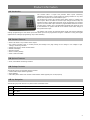
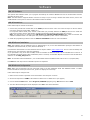
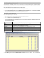
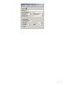
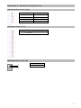
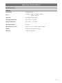
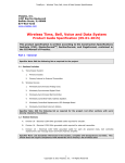
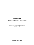
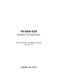
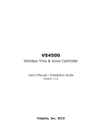
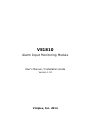
VS1810 Alarm Input Monitoring Module User's Manual / Installation Guide Version 1.02 Visiplex, Inc. 2014 VS1810 Alarm Input Monitoring Module Copyright The product described in this manual includes copyrighted Visiplex computer programs stored in semiconductor memories and computer files. As such, these programs may not be copied or reproduced in any manner without the express written permission of Visiplex, Inc. Disclaimer The information within this document has been carefully checked and is assumed to be accurate and reliable. However, no responsibility is assumed for inaccuracies. Visiplex, Inc. reserves the right to make changes to any of the products herein to improve reliability, functionality or design. Copyright ©Visiplex, Inc. Buffalo Grove, IL 2014 About This Manual This VS1810 User’s Manual / Installation Guide describes the installation and setup procedures of the VS1810 for alarm and dry-contact input monitoring. It is imperative the manual is followed in the order it is presented to prevent damage to the equipment, as well as insuring proper system functionality. 2 Table of Contents Product Information 1.1 Introduction 1.2 Standard Features 1.3 Optional Features 1.4 Package Contents 1.5 Key Navigation Installation 2.1 Site Inspection and System Location 2.2 Alarm Input Connections 2.3 Operation Modes and Serial Data Output Advanced System Information 3.1 Administration Menu 3.1.1 Alarm Edit Menu 3.1.2 Time Setup Menu 3.1.3 Date Setup Menu 3.1.4 Time Zone Setup Menu 3.1.5 Daylight Saving Mode Menu 3.1.6 Serial Port Mode Menu 3.1.7 Serial Settings Menu 3.1.8 Reset Database Menu 3.1.9 System Password Menu 3.1.10 Device Database Menu 3.1.11 Wireless Setup Menu 3.1.12 Coverage Test Menu 3.3 Alarm Input Monitoring Menu Software 4.1 VPS 4.1.1 Connections 4.1.2 Software Installation 4.1.3 Software Configuration 4.1.4 Setting Date and Time from PC 4.1.5 Alarm Input Programming Appendices 5.1 Appendix A – Connections, Wiring and Pin Out 5.2 Appendix B – Connections, Wiring and Pin Out General Information 6.1 Specifications 6.2 Warranty 4 4 4 4 4 5 5 5 6 6 7 8 8 8 8 9 9 9 9 10 11 11 12 12 12 12 13 13 16 17 18 19 3 Product Information 1.1 Introduction The VS1810 offers a simple and powerful alarm inputs monitoring capabilities and provides a serial interface to paging encoders or any other device that requires serial communication input. The VS1810 can monitor dry-contact closure alarm inputs or voltage level alarm inputs. When the status of an alarm input changes to ON or OFF, the VS1810 provides a serial data output that can be processed by any external system. The serial data output includes a programmable subscriber number (usually pager number) and a programmable message that should be sent to the subscriber or system that has to be notified of the status change of the specific alarm input. The VS1810 can monitor 96 individual alarm inputs and supports individual settings programming for each alarm input. Each alarm input can be programmed using the V software or using the keypad (alphanumeric messages programming require VPS software). 1.2 Standard Features Built-in 96 alarm or dry-contact closure inputs Dry Contact (normally open or normally closed) and Voltage Level (high voltage to low voltage or low voltage to high voltage) monitoring interface RS232 serial port for serial communication Backlit LCD display Numeric keypad Built-in memory backup Desk or wall mountable 1.3 Optional Features Pulse / Flash Mode monitoring interface 1.4 Package Contents The following items are included with the VS1810: VS1810 Alarm Input Monitoring Module Power adaptor USB cable (Note: RS232 null-modem communication cable supplied prior to 04/01/2014) 1.5 Key Navigation The following keys also function in system menus as detailed below: # Select / Acknowledge / Enter * Return to previous menu / Escape 1 On / Next 0 Off / Previous 4 Installation 2.1 Site Inspection and System Location Consider the following requirements when planning system installation and choosing a location for the VS1810 and other system components: 1. Choose a location that is easily accessible in case you need to perform maintenance on VS1810. 2. Install a UPS power backup to protect the system from power outages and surges. If you are using an external encoder, place it next to the VS1810 and use the data cable provided to connect the VS1810 and the external encoder. 3. Connect the provided power supply to the POWER jack at the back of the VS1810 and turn the power switch to ON position. 2.2 Alarm Input Connections Alarm inputs should be connected to the DB25 connectors marked as ALARM INPUTS 1-24, ALARM INPUTS 25-48, ALARM INPUTS 49-72 and ALARM INPUTS 73-93 at the back panel of the VS1810 (refer to Alarm Input Pin Out on page 16 for more information). Each alarm input requires a set of 2 wires: Dry Contact Closure monitoring requires non-polarized 2 wires while Voltage Level monitoring requires polarized 2 wires (+ and -). All alarm inputs on a specific DB25 connector should share the same GROUND (or the - wire) by connecting them to Pin 1 of the specific DB25 connector at the back panel of the VS1810. The other wire (or the + wire) should be connected to one of the other pins on the DB25 connector (Pins 2-25). An alarm input status changes when one of the following conditions is true: 1. For Dry Contact Closure: Pin 1 is shorted with the pin corresponding to the alarm input (for normally open input type) or when Pin 1 is disconnected from the pin corresponding to the alarm input (for normally closed input type). For example, for normally open input type, if Pin 1 is shorted with Pin 5, Alarm 4 is considered to be ON. 2. For Voltage Level and Pulse / Flash Mode: The voltage level measured between Pin 1 (-) and the pin corresponding to the alarm input (+) compared to the Threshold Level settings for the alarm input determines if the alarm is ON or OFF. For example, for Voltage Low-High alarm input type, if the voltage measured between Pin 1 and Pin 5 is 12VDC and the Threshold Level for this alarm input is set to 5 VDC, Alarm 4 is considered to be ON. 2.3 Operation Modes and Serial Data Output The VS1810 is available in two operation modes: 1. Paging Encoder Interface Mode: When an alarm input status changes, the VS1810 sends a serial data using the VISIPLEX serial protocol. The data output includes the subscriber number and the message that should be sent to the subscriber. The VISIPLEX serial protocol format is listed below: Command format: PnnnM<CR> P – Fixed prefix (must be capital P). nnn – 3 digit valid subscriber, device or pager number. M – Alphanumeric message. <CR> - Carriage Return (ASCII 13) Serial Input and Output: VS1810 Output Terminal Response PnnnM<CR> None (paging encoder is required to process the paging request according to its database) Terminal Output VS1810 Response <CR> ?99<CR> NOTE: Paging Encoder Interface Mode is the default operation mode and is compatible with Visiplex paging encoders. 2. Alarm Input Status Mode: This mode is reserved for specific Visiplex systems that require alarm input status only while the processing of the required response is performed by external system. This operation mode is activated only if the VS1810 is supplied for a compatible Visiplex system. 5 Advanced System Information The main menu shown below appears after the VS1810 is turned on and is used for accessing the Programming and Administration menus. VS1810 11:54 MONITORING... 3.1 Administration Menu From the Main Menu press the B key. Enter 1810 as password. The prompt Select Option will appear on the top line. The Administration Menu provides access to the following available sub-menus: 1. Alarm Editing Menu 2. Time Setup 3. Date Setup 4. Time Zone Setup 5. Daylight Saving Mode 6. Serial Port Mode 7. Serial Port Baud Rate 8. Reset Database 9. System Password A. Device Database B. Wireless Setup C. Coverage Text D. TX Test Tone To access a specific sub-menu, press the digit key representing it. 3.1.1 Alarm Edit Menu Note: The VPS software provides an easy programming and database backup interface. It is recommended that VPS will be used for these tasks. From the Administration Menu, select 1 followed by the # key. The prompt Alarm Editing will appear on the top line. Enter a value between 1 and 2 to determine the programming type: 1 –Single alarm point 2 – Range of alarm points. This option allows the user to program multiple alarm inputs as long as they are within a sequential range. Enter the number of the first input you wish to program as a 2-digit number (for example, “01”) and press the # key. Enter the number of the last input you wish to program as a 2-digit number (for example, “20”) and press the # key. Following are the fields description Input Type Select the required input type and press the # key: 1 – Dry Contact N.O (Normally Open, alarm will be triggered when contact is closed) 2 – Dry Contact N.C (Normally Closed, , alarm will be triggered when contact is opened) 3 – Voltage High-Low (alarm will be triggered when voltage level changes to a level below the Threshold Level) 4 – Voltage Low-High (alarm will be triggered when voltage level changes to a level above the Threshold Level) 5 – Pulsing High-Low (alarm will be triggered when voltage level fluctuates between the normal voltage and the below Threshold Level, the normal voltage is higher than the Threshold Level) 6 – Pulsing Low-High (alarm will be triggered when voltage level fluctuates between the normal voltage and above Threshold Level, the normal voltage is lower than the Threshold Level) 7 – Double Mode Low (alarm will be triggered in either Voltage Low-High or Pulsing Low-High) 8 – Double Mode High (alarm will be triggered in either Voltage High-Low or Pulsing High-Low) Note: Input types 5-8 are optional. Pulse Rate 1 – 1 Per Seconds (voltage level fluctuates once per second between the normal voltage and the Threshold Level) 2 – 2 Per Seconds (voltage level fluctuates twice per second between the normal voltage and the Threshold Level) Note: This setting is only available for input type 5-8. 6 Threshold Level Activation Plan Send to Pager Alarm Message Cancel Pager Cancel Message Repeat Page Input Delay Enter a value between -12V and 12V representing the normal voltage level. Use the A key for positive voltage and the B key for negative voltage. For example, for -10V, enter 10 followed by the B key and press the # key. Note: This setting is only available for input type 5-8. Determines when the alarm monitoring is active. The system will send a message to the designated device only if the alarm is triggered during the monitored time. Enter a number from 0 to 9. 0 - Always Active 1 - Daily, 6PM-8AM 2 - Weekdays Only, 6PM-8AM 3 - Daily, 8PM-6AM 4 - Daily, 10PM-6AM 5 - Daily, 10PM-5AM 6 - Daily, 6AM-10PM 7 - Weekdays Only, 6AM-10PM 8 - Daily, 8AM-6PM 9 - Weekdays Only, 8AM-6PM Note: The execution of the activity plan is dependent on the time stored the VS1810 internal clock. This clock should be kept accurate by receiving time updates from a PC connected to the VS1810 via a serial port. Enter a value (001 to 999) representing the device that should be activated by the paging encoder connected to the VS1810 when the alarm input changes from OFF to ON. Press the # key. The VS1810 will send a request to send a message to that device using Visiplex protocol. Note: A value of “000” will cause the VS1810 to not send the paging request and the alarm activation will be ignored. The message that should be sent to the paging encoder connected to the VS1810 when the alarm input changes from OFF to ON. Press the # key. Note: The message is programmable using the VPS software. Enter a value (001 to 999) representing the device that should be activated by the paging encoder connected to the VS1810 when the alarm input changes from ON to OFF. Press the # key. The VS1810 will send a request to send a message to that device using Visiplex protocol. Note: This feature is not active unless specifically requested by the customer – contact Visiplex technical support for more information. A value of “000” will cause the VS1810 to not send the paging request and the alarm deactivation will be ignored. The message that should be sent to the paging encoder connected to the VS1810 when the alarm input changes from ON to OFF. Press the # key. Note: This feature is not active unless specifically requested by the customer – contact Visiplex technical support for more information. The message is programmable sing the VPS software. Determines if the message should be repeated as long as the alarm is ON, and the maximum number of repeat messages. The message will be repeated every minute. Enter a number from 00 to 99. Determines if a message should be sent immediately when the alarm is triggered or only if it was triggered for a period of time longer than Input Delay. Enter a number from 000 to 240 seconds. After the last step is completed, the display will change to Update Changes ?. Press the # to save changes or press * to cancel changes. 3.1.2 Time Setup Menu From the Administration Menu, select 2 followed by the # key. The following screen will be displayed: ENTER GMT TIME: 12:00 Enter the UTC (Universal Coordinate Time) or GMT (Greenwich Mean Time) time in 24 hours (military) format. The display will change back to Time Setup. DO NOT enter the local time as the unit uses the universal atomic time as a reference and calculates the local time based on your Time Zone. If the VS1810 is connected to a PC, it will revert back to the source time few minutes later overwriting the time changes made. 7 3.1.3 Date Setup Menu From the Administration Menu, select 3 followed by the # key. The following screen will be displayed: ENTER GMT DATE: 010111 Enter the UTC (Universal Coordinate Time) or GMT (Greenwich Mean Time) date in MMDDYY format. The display will change back to Date Setup. DO NOT enter the local date as the unit uses the universal atomic time as a reference and calculates the local time based on your Time Zone. If the VS1810 is connected to a PC, it will revert back to the source time few minutes later overwriting the time changes made. 3.1.4 Time Zone Setup Menu From the Administration Menu, select 4 followed by the # key. The following screen will be displayed: TIME ZONE SETUP: 06 Enter the offset in hours of the local time zone from UTC (Universal Coordinate Time) or GMT (Greenwich Mean Time) time. Use 01 to 23 for negative offset (GMT -1 to GMT -23), 00 or 24 for GMT time, 25 to 47 for positive offset (GMT+1 to GMT+23). For examples, for the following time zones, enter the following values: Eastern Time: 05 Central Time: 06 Mountain Time: 07 Pacific Time: 08 Alaska Time: 09 Hawaii Time: 10 After the last step is completed, the display will return to the Administration Menu. 3.1.5 Daylight Saving Mode Menu From the Administration Menu, select 5 followed by the # key. The following screen will be displayed: DL SAVING MODE: ENABLED Enter a value between 0 and 1 followed by # key to save the settings: 0 – Disabled 1 – Enabled 3.1.6 Serial Port Mode Menu From the Administration Menu, select 6 followed by the # key. The following screen will be displayed: Use this option to select the active serial communication output mode. SERIAL PORT MODE BUFFERRED MODE Enter the serial communication protocol that should be used on COM1. Enter a value between 1 and 3 followed by # key to save the settings: 1 – Status Only (required for operation with VNS5100, alarm points must be set as active) 2 – Encoder Mode: Paging request using standard VISIPLEX protocol. Requests are sent as soon as an alarm point status changes. 3 – Buffered Mode: Delayed Paging request using standard VISIPLEX protocol. Paging requests are queued and processed sequentially (one at a time) after previous request has been sent to the encoder. 8 3.1.7 Serial Settings Menu From the Administration Menu, select 7 followed by the # key. The following screen will be displayed: Use this option to select the settings (baud rate, parity, data bits, stop bits) used on COM1. SERIAL BAUDRATE: 38400BPS 8,N,1 Enter the serial communication settings (baud rate, parity, data bits, stop bits) that should be used on COM1. Enter a value between 0 and 9, A or B followed by # key to save the settings: 0 – 1200 bps, 7,E,1 1 – 1200 bps, 8,N,1 2 – 2400 bps, 7,E,1 3 – 2400 bps, 8,N,1 4 – 9600 bps, 7,E,1 5 – 9600 bps, 8,N,1 6 – 19200 bps, 7,E,1 7 – 19200 bps, 8,N,1 8 – 38400 bps, 7,E,1 9 – 38400 bps, 8,N,1 A – 57600 bps, 7,E,1 B – 57600 bps, 8,N,1 3.1.8 Reset Database Menu NOTE: This is an IRREVERSIBLE command - DO NOT select this option unless you are absolutely sure you want to clear all devices and pre-programmed messages data. You may want to transcribe this information to paper first or use the optional PC software to backup the data to a computer. From the Administration Menu, select 8 followed by the # key. CLEAR ALL DATA.. ARE YOU SURE??? Press # to confirm the Database Reset. Press * or any other key to cancel and return to the Administration Menu. 3.1.9 System Password Menu From the Administration Menu, select 9 followed by the # key. The following screen will be displayed: SYSTEM PASSWORD: 1810 Enter the new administrator password that will be required to access the Administration Menu and other system menus. The default password is 1810. 3.1.10 Device Database Menu Note: This section is reserved for future use and applicable to units equipped with internal transmitters only. From the Administration Menu, select A followed by the # key. Following are the fields description: Device to Edit Device Capcode Device Type Enter 3 digit ID of the programmed device (001-899). If the device already exists, its details will be displayed for editing or deleting. Group devices (01-99) are represented and accessed by paging to devices 901-999. Enter the capcode of the programmed device. For Voice pagers, enter “0” followed by Tone A and Tone B (for example, “0110111”). Select the type of the programmed device. 0 - Alphanumeric Pager 1 - Numeric Pager 2 - Tone Only Pager 3 - Voice Pager 4 - Wireless Speaker 5 - LED Display 9 Paging Mode Group Select Mode and Baud Rate and press the # key: 1 – 512 bps, Mode 0 2 – 512 bps, Mode 1 3 - 512 bps, Mode 2 4 – 512 bps, Mode 3 5 – 1200 bps, Mode 0 6 – 1200 bps, Mode 1 7 - 1200 bps, Mode 2 8 – 1200 bps, Mode 3 9 – 2400 bps, Mode 1 0 – 2400 bps, Mode 2 If the device is a member in a group, enter the group number (0-99) and press the # key. Group devices are represented and accessed by paging to devices 901-999. Note: Underlined values indicate default values. After the last step is completed, the display will flash DATA SAVED and return to the Device to Edit menu. Repeat the above steps for additional devices or press the * key twice to return to the Main Menu. 3.1.11 Wireless Setup Menu From the Administration Menu, select B followed by the # key. The following screen will be displayed: WIRELESS SETUP: PA VOLUME This screen allows the administrator to configure different wireless settings of the VS1810. Press the key representing the field followed by # key to edit the settings. Following are the fields description: 1 - PA Volume 2 - PA Timeout 3 – LED Display Mode 4 – LED Color 5 – LED Text Mode 6 – Led Font Style 7 – LED Timeout Mode 8 - Pre-Page Delay Determines the default volume used in voice messaging. Enter a value of 1 (lowest), 2, 3 or 4 (highest) followed by # key to save the settings. Determines the time period after which the transmission of voice message will be terminated. Enter a value between 1 and 8 followed by # key to save the settings: 1 – 30 seconds 2 – 60 seconds 3 – 1.5 minutes 4 – 2 minutes 5 – 2.5 minutes 6 – 3 minutes 7 – 3.5 minutes 8 – 4 minutes Determines if the messages sent to alphanumeric display should overwrite the displayed message or added to the current queue of messages displayed by the alphanumeric display. Enter a value between 1 and 2 followed by # key to save the settings: 1 – New messages overwrite the currently displayed message. 2 – New messages are added to the list of messages (messages will be displayed one after the other according to the messages parameters). Determines the default color that should be used to display messages sent to alphanumeric displays. Enter a value according to the settings supported by the alphanumeric display. Note: Please refer to the alphanumeric display instructions sheet for more information. Determines the default effect that should be used to display messages sent to alphanumeric displays. Enter a value according to the settings supported by the alphanumeric display. Note: Please refer to the alphanumeric display instructions sheet for more information. Determines the default font that should be used to display messages sent to alphanumeric displays. Enter a value according to the settings supported by the alphanumeric display. Note: Please refer to the alphanumeric display instructions sheet for more information. Determines the default time slice that should be used to display messages sent to alphanumeric displays. Enter a value according to the settings supported by the alphanumeric display. Note: Please refer to the alphanumeric display instructions sheet for more information. Determines if a delay will be applied before the transmission of data for digital paging. Enter a value between 0 and 1 followed by # key to save the settings: 0 – Disabled 1 – Enabled 10 9 – Security Mode 0 – Security Code B – TX Data Polarity C – TX Deviation D – Call Sign Determines if secure data mode should be used. This provides data encryption to secure the transmission to the wireless receivers using the security key. Enter a value between 0 and 9 followed by # key to save the settings: 0 – Disabled 1 – Mode 1 2 – Mode 2 3 – Mode 3 4 – Mode 4 5 – Mode 5 6 – Mode 6 7 – Mode 7 8 – Mode 8 9 – Mode 9 Determines the security key for secure data mode. Enter a value between 0 and 299. Determines if the transmitter data should be inverted. Enter a value between 0 and 1 followed by # key to save the settings: 0 – Normal 1 – Inverted Determines the TX deviation. Enter a value between 1 and 9 followed by # key to save the settings: 1 – ±0.5kHz 2 – ±1.0kHz 3 – ±1.5kHz 4 – ±2.0kHz 5 – ±2.5kHz 6 – ±3.0kHz 7 – ±3.5kHz 8 – ±4.0kHz 9 – ±4.5kHz Displays the call sign assigned to you by the FCC (if any). Contact Visiplex tech support for more details. Note: Underlined values indicate default values. Press the * key to return to the Administration Menu. 3.1.12 Coverage Test Menu Note: This section is reserved for future use and applicable to units equipped with internal transmitters only. From the Administration Menu, select C followed by the # key. Enter a value between 1 and 8 to determine the cover page interval: 1 2 3 4 5 6 7 8 – – – – – – – – Every Every Every Every Every Every Every Every 5 seconds 10 seconds 15 seconds 20 seconds 30 seconds 1 minute 2 minutes 4 minutes Use this option to send cover page to device 100. This feature is useful when testing the transmitter coverage area. Press * to cancel and return to the Administration Menu. Press the * key to return to the Main Menu or repeat the procedure to edit additional alarm inputs. 3.2 Alarm Input Monitoring Menu This menu allows the user to monitor the status of an alarm input. From the Main Menu press the A key. The prompt Input Number will appear on the top line. Enter the number of the input you wish to monitor as a 2-digit number (for example, “01”). Press the * key to return to the Alarm Input Monitoring Menu and select a different alarm input. 11 Software 4.1 VPS Software The optional VPS software allows you to program and backup the VS1810 database and set the VS1810 date and time according to the PC clock. Note: The VPS software supports VS1810 version 2.10 and up. If you are using a VS1810 with earlier version, refer to the VisiDB software and a previous version of the VS1810 manual for details. 4.1.1 Connections Follow these steps to connect the VS1810: 1. Connect the provided null modem cable to the COM1 port and the other end to one of the serial port on the PC. Make a note of the serial port used (COM1, COM2, etc.). For computers without serial ports, connect a USB cable (not provided) between the USB port and the PC. Install the USB drivers provider with the VPS software according to Winodws operating system used (32 or 64 bit). Note: The USB drivers are located in the USB Drivers for VS1810-VS4500-VS4800 folder under the selected VPS software instalaltion folder. The USB option may not be supported by older version of the VS1810. 2. Install the programming software. Refer to Software Installation section for more information. 4.1.2 Software Installation Note: VPS software must be installed by the PC administrator or by a user with administrator privileges. VPS software is compatible with Windows ME, XP, 2000, Vista and Windows 7. Download the VPS software from the Download Area of Visiplex website (www.visiplex.com), save it to the PC Desktop and double click on the saved file to start the installation. If you purchased a copy of the VPS CD-ROM, locate the software CD-ROM and insert it to the CD-ROM drive on the PC. If the installation program doesn’t start automatically within 5 seconds, use Windows Explorer to browse to the CD-ROM drive and then run the VPS_Setup.exe file. Note: For Windows Vista and Windows 7, it is recommended that the installation folder will be set to “C:\Visiplex\VPS”). Press Next on each step until the installation process is completed. 4.1.3 Software Configuration Note: Make sure the Windows user has full access rights to the VPS installation folder and databases folders. To obtain further information and help for each screen, press F1 to display the online help. Follow these steps to configure VPS: 1. Make sure the VS1810 is powered on and connected to the serial port on the PC. 2. Set the serial protocol on COM1 of the VS1810 to 9600-8-N-1 or 38400-8-N-1 (see page 9). 3. Click on Windows Start button. Select Programs, VISIPLEX program group, VPS and then click on VPS. 4. The auto detection dialog box will be displayed. Press Ok to start device detection. 12 4.1.4 Setting Date and Time from PC Synchronizing the VS1810 date and time to the PC clock allows you to keep the VS1810 internal clock accurate without using an external time source. This action can be performed manually or automaticaly as long as the VS1810 is connected to the PC and VPS is running. Follow these steps to synchronize date and time to the PC date and time: 1. Make sure the VS1810 is powered on and connected to the serial port on the PC. 2. To set the date and time automtically, click on Settings, Configuration & Settings. Click on Synchronize Connected Device to PC Clock Automtically and then click on Save. This will synchronize the VS1810 clock to the PC clocks periodically every hour. 4.1.5 Alarm Input Programming Follow these steps to program an alarm input: 1. Make sure the VS1810 is powered on and connected to the serial port on the PC. 2. Click on VS1810, Pre-Programmed Message menu. 3. The Alarm Messages dialog box will be displayed. The last alarm programming file edited by the user will be retrieved from the disk and displayed. If this file does not exist, a new file will be created by the VPS software. Below are the fields and functions description: Close Edit Upload Close the Alarm Message dialog box. Display a dialog box that allows updating the specific highlighted alarm input on the alarm input list (see step 4). Upload the displayed alarm input programming file in to the VS1810 memory. This command will overwrite the existing programming in the VS1810. Download Download the alarm input programming from the VS1810 memory to the PC. Open Retrieve and display a previously saved alarm input programming file. Save As Save the displayed alarm input programming to a file on the PC for later use. File Name Name of alarm input file displayed. Work Offline Allows performing alarm inputs setting to a file only without programming the VS1810 (usually followed by the Upload command). 4. If the Edit command is selected, the Alarm Messages – Edit dialog box will be displayed. Below are the fields and functions description: 13 Save Update the alarm input file and VS1810 (if Work Offline box is cleared) with changes. Note: If the Work Offline check box is checked, changes made to the alarm input programming are only saved to the disk and are not written in to the VS1810 memory. To program the VS1810, click on Upload when all changes have been applied. Cancel Ignore all changes and exit. Device ID Message Cancel Message Input Delay Repeat Time Activation Plan Send Cancel Page Cancel Pager Input Type Threshold Level Pulse Active Enter a value (001 to 999) representing the device that should be activated by the paging encoder connected to the VS1810 when the alarm input changes from OFF to ON. The VS1810 will send a request to send a message to that device using Visiplex protocol. Note: A value of “000” will cause the VS1810 to not send the paging request and the alarm activation will be ignored. The message that should be sent to the paging encoder connected to the VS1810 when the alarm input changes from OFF to ON. The message that should be sent to the paging encoder connected to the VS1810 when the alarm input changes from ON to OFF. Note: This feature is not active unless specifically requested by the customer – contact Visiplex technical support for more information. Determines if a message should be sent immediately when the alarm is triggered or only if it was triggered for a period of time longer than Input Delay. Enter a number from 000 to 240 seconds. Determines if the message should be repeated as long as the alarm is ON, and the maximum number of repeat messages. The message will be repeated every minute. Enter a number from 00 to 99. Determines when the alarm monitoring is active. The system will send a message to the designated device only if the alarm is triggered during the monitored time. Enter a number from 0 to 9. 0 - Always Active 1 - Daily, 6PM-8AM 2 - Weekdays Only, 6PM-8AM 3 - Daily, 8PM-6AM 4 - Daily, 10PM-6AM 5 - Daily, 10PM-5AM 6 - Daily, 6AM-10PM 7 - Weekdays Only, 6AM-10PM 8 - Daily, 8AM-6PM 9 - Weekdays Only, 8AM-6PM Note: The execution of the activity plan is dependent on the time stored the VS1810 internal clock. This clock should be kept accurate by receiving time updates from a PC connected to the VS1810 via a serial port. Not applicable – see VS1810 Options section. Enter a value (001 to 999) representing the device that should be activated by the paging encoder connected to the VS1810 when the alarm input changes from ON to OFF. The VS1810 will send a request to send a message to that device using Visiplex protocol. Note: This feature is not active unless specifically requested by the customer – contact Visiplex technical support for more information. A value of “000” will cause the VS1810 to not send the paging request and the alarm activation will be ignored. Assign the type of alarm input: 1 – Dry Contact N.O (Normally Open, alarm will be triggered when contact is closed) 2 – Dry Contact N.C (Normally Closed, , alarm will be triggered when contact is opened) 3 – Voltage High-Low (alarm will be triggered when voltage level changes to a level below the Threshold Level) 4 – Voltage Low-High (alarm will be triggered when voltage level changes to a level above the Threshold Level) 5 – Pulsing High-Low (alarm will be triggered when voltage level fluctuates between the normal voltage and the Threshold Level, the normal voltage is higher than the Threshold Level) 6 – Pulsing Low-High (alarm will be triggered when voltage level fluctuates between the normal voltage and the Threshold Level, the normal voltage is lower than the Threshold Level) 7 – Double Mode Low (alarm will be triggered in either Voltage Low-High or Pulsing Low-High) 8 – Double Mode High (alarm will be triggered in either Voltage High-Low or Pulsing High-Low) Note: Input types 5-8 are optional. Enter a value between -12V and 12V representing the normal voltage level. Note: This setting is only available for input type 5-8. 1 – 1 Per Seconds (voltage level fluctuates once per second between the normal voltage and the Threshold Level) 2 – 2 Per Seconds (voltage level fluctuates twice per second between the normal voltage and the Threshold Level) Note: This setting is only available for input type 5-8. Determines if the alarm pint is active. Inactive alarm point will not generate paging requests. 14 15 Appendices 5.1 Appendix A – Installation Diagrams Magnetic Mount Antenna (Optional Base Antenna) Coaxial Cable (BNC to BNC) Alarm Inputs RF Out (Future use, internal Transmitter Only) VS1810 USB RS232 PC Interface Low Power System Installation Diagram 16 5.2 Appendix B – Connections, Wiring and Pin Out 5.2.1 Serial Port Pin Out (COM1) 1 – N.C. 6 – N.C. 2 – RX (IN) 7 – DSR (OUT) 3 – TX (OUT) 8 – N.C. 4 – RTS (OUT) 9 – N.C. 5 – GND 5.2.2 Alarm Input Pin Out 1 – GND 2 to 25 – Alarm Inputs 1 to 24, 25 to 48, 49 to 72, 73 to 96 5.2.3 Power Port Pin Out (DC) 1 1 – POS (CENTER) 2 – GND 2 17 General Information 6.1 Specifications General Data Format Serial Data Output Power AC Adaptor - Input: 100-240VAC, 50/60Hz Output: 12VDC, 3A Approvals UL/CSA listing (power supply) Operating Temperature 32º to 104º F / 0º to 40º C Storage Temperature 14º to 140º F / -10º to 60º C Operating Humidity 10%-65% Dimensions (W x H x D) 9.75" x 2.5" x 5.5" / 248mm x 63mm x 140mm Weight 2.10 lbs. / 2.6 lbs with power supply Warranty 1 Year, Parts and Labor 18 6.2 Warranty Unless otherwise specified at the time of original purchase, all equipment is warranted as to quality and performance for one year from the date of original shipment from our factory. This factory warranty covers all parts, software, and/or labor (as specified at time of purchase) at our factory, as well as return shipping to you, the customer, but does not apply to any batteries or other damage resulting from abuse of the equipment. Warranty coverage excludes free replacement of cosmetic items such as clips, logos, etc. The warranty is void if: 1. There is evidence of abuse to the equipment (i.e., corrosion, unusual physical damage, signs of exposure to temperatures outside the range of specifications, etc.) 2. The equipment contains an unauthorized modification. 3. Identification numbers on the printed circuit boards or chassis have been altered or removed. 4. Evidence of the product having been exposed to or submerged in water. 5. Equipment is damaged through acts of God, including, but not limited to: flood, lightning, hurricane, tornado, sustained high winds, acts of war, natural disasters, etc. Should you experience problems with any product, we would suggest consulting your system or clock maintenance guide to correct any routine problems such as replacing batteries, cleaning contacts, checking AC voltage, etc. If the problem persists, please call our technical support department for additional assistance, remote diagnostics help, etc. If your product must be returned for repair, our technical service department will provide you with a Returned Material Authorization (RMA) number and any other special instructions that will allow the repair to be handled as quickly as possible. All non-warranty products require a purchase order number in addition to an RMA number for repair work to be started. For more information, or to obtain technical assistance on any warranty or non-warranty product, please write, call, fax or email to: Visiplex, Inc. 1287 Barclay Boulevard Buffalo Grove, IL 60089 Phone: (847) 229-0250 or (877) 918-7243 Fax: (847) 229-0259 E-mail: [email protected] Website: www.visiplex.com Business Hours: Monday-Friday, 9:00 AM - 5:00 PM Central Time. 19