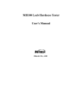
1
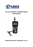
MT200
Ultrasonic Thickness Gauge
User’s Manual
Mitech Inc. Ltd.
NDTzone • Non-Destructive Testing Equipment Specialists
Tel.: +1.877.363.4243 • eMail: [email protected] • Web: www.NDTzone.com
MITECH
T1 Overview ...................................................................... 4
1.1 Product Specifications......................................... 4
1.2 Main Functions..................................................... 5
1.3 Measuring Principle............................................. 5
1.4 Configuration ........................................................ 6
1.5 Operating Conditions .......................................... 7
2 Structure Feature .......................................................... 8
2.1 Instrument Appearance....................................... 8
2.2 Parts of the Main Body ....................................... 8
2.3 Measurement Screen........................................ 10
2.4 Keypad Definitions............................................. 13
3 Preparation................................................................... 14
3.1 Transducer Selection ........................................ 14
3.2 Condition and Preparation of Surfaces .......... 19
4 Operation...................................................................... 20
4.1 Power On/Off...................................................... 20
4.2 Transducer Set................................................... 20
4.3 Probe Zero.......................................................... 21
4.4 Sound Velocity ................................................... 22
4.5 Making Measurements ..................................... 26
4.6 Two Point Calibration ........................................ 27
4.7 Scan mode.......................................................... 29
4.8 Limit Set .............................................................. 31
4.9 Resolution ........................................................... 31
2
NDTzone • Non-Destructive Testing Equipment Specialists
Tel.: +1.877.363.4243 • eMail: [email protected] • Web: www.NDTzone.com
MITECH
4.10 Unit Scale ......................................................... 32
4.11 Memory Management ..................................... 32
4.12 Data Printing..................................................... 35
4.13 System Set ....................................................... 35
4.14 System information ......................................... 36
4.15 EL Backlight...................................................... 36
4.16 Battery Information.......................................... 36
4.17 Auto Power Off................................................. 38
4.18 System Reset................................................... 38
4.19 Connecting to a Computer ............................. 38
5 Menu Operation........................................................... 39
5.1 Enter the Main Menu......................................... 40
5.2 Enter the Sub menu .......................................... 40
5.3 Change the Parameter ..................................... 40
5.4 Numeric Digit Input............................................ 40
5.5 Save and Exit ..................................................... 40
5.6 Cancel and Exit.................................................. 40
6 Servicing....................................................................... 41
7 Transport and Storage................................................ 41
Appendix A Sound Velocities........................................ 42
Appendix B Applications Notes .................................... 44
3
NDTzone • Non-Destructive Testing Equipment Specialists
Tel.: +1.877.363.4243 • eMail: [email protected] • Web: www.NDTzone.com
MITECH
1 Overview
The Mitech model MT200 is a digital ultrasonic
thickness gauge. Based on the same operating principles as
SONAR, the MT200 is capable of measuring the thickness
of various materials with accuracy as high as 0.01
millimeters, or 0.001inches. It is suitable for a variety of
metallic and non-metallic materials.
1.1 Product Specifications
1)
2)
3)
4)
5)
6)
7)
Display:128×64 dot matrix LCD with EL backlight.
Measuring Range:0.75~300mm (in Steel).
Sound Velocity Range: 1000~9999 m/s.
Resolution:0.1/0.01mm(selectable).
Accuracy: ±(0.5%Thickness+0.04)mm
Units: Metric/English unit selectable.
Four measurements readings per second for single
point measurement, and ten per second for Scan Mode.
8) Memory for 20 files (up to 99 values for each file) of
stored values.
9) Upper and lower limit can be pre-set. It will alarm
automatically when the result value exceeding the limit.
10) Power Supply:Two “AA” size, 1.5 volt alkaline batteries.
100 hours typical operating time (EL backlight off).
11) Communication:RS232 serial port.
12) Case:Extruded aluminum body suitable for use under
4
NDTzone • Non-Destructive Testing Equipment Specialists
Tel.: +1.877.363.4243 • eMail: [email protected] • Web: www.NDTzone.com
MITECH
poor working conditions.
13) Outline dimensions:132H X 76.2W mm.
14) Weight:345g
1.2 Main Functions
1) Capable of performing measurements on a wide range
of material, including metals, plastic, ceramics,
composites, epoxies, glass and other ultrasonic wave
well-conductive materials.
2) Four transducer models are available for special
application, including for coarse grain material and high
temperature applications.
3) Probe-Zero function, Sound-Velocity-Calibration function
4) Two-Point Calibration function.
5) Two work modes: Single point mode and Scan mode.
6) Coupling status indicator showing the coupling status.
7) Battery information indicates the rest capacity of the
battery.
8) Auto sleep and auto power off function to conserve
battery life.
9) Optional software to process the memory data on the
PC.
10) Optional thermal mini-printer to print the measured data
via RS232 port.
1.3 Measuring Principle
The digital ultrasonic thickness gauge determines the
5
NDTzone • Non-Destructive Testing Equipment Specialists
Tel.: +1.877.363.4243 • eMail: [email protected] • Web: www.NDTzone.com
MITECH
thickness of a part or structure by accurately measuring the
time required for a short ultrasonic pulse generated by a
transducer to travel through the thickness of the material,
reflect from the back or inside surface, and be returned to
the transducer. The measured two-way transit time is
divided by two to account for the down-and-back travel path,
and then multiplied by the velocity of sound in the material.
The result is expressed in the well-known relationship:
H=
v×t
2
Where: H-Thickness of the test piece.
v-Sound Velocity in the material.
t-The measured round-trip transit time.
1.4 Configuration
Table 1-1
Standard
Configur
ation
No
.
1
2
Item
Quantity
Main body
Transducer
1
1
3
4
5
6
7
8
Couplant
Instrument Case
Operating Manual
Screwdriver
Alkaline battery
1
1
1
1
2
Note
Model:
N05/90°
AA size
6
NDTzone • Non-Destructive Testing Equipment Specialists
Tel.: +1.877.363.4243 • eMail: [email protected] • Web: www.NDTzone.com
MITECH
Optional
Configur
ation
9
10
11
12
13
14
15
Transducer: N02
Transducer: N07
Transducer: HT5
Mini
thermal
printer
Print cable
DataPro
for
Thickness Gauge
Communication
Cable
See
Table3-1
1
1
1
For use on
the PC
1
1.5 Operating Conditions
Operating Temperature: -20~+60℃;
Storage Temperature:-30℃~+70℃
Relative Humidity ≤90%;
The surrounding environment should avoid of vibration,
strong magnetic field, corrosive medium and heavy dust.
7
NDTzone • Non-Destructive Testing Equipment Specialists
Tel.: +1.877.363.4243 • eMail: [email protected] • Web: www.NDTzone.com
MITECH
2 Structure Feature
2.1 Instrument Appearance
1 Main Body
MT200
2 Transducer
1
2
MiTec h
2.2 Parts of the Main Body
7
MT200
6
9
THICKNESS GAUGE
10
POWER: 2 X 1.5V
SN:
OPERATION GUIDE
2
5
8
1. Plug in the transducer
2.
Power On/Off
3.
Backlight On/Off
4.
Probe Zero
5.
Switch Selection
6.
Save/Delete
7.
Exit
8.
M iTec h
3
Enter
MiTech Inc. Ltd
4
NDTzone • Non-Destructive Testing Equipment Specialists
Tel.: +1.877.363.4243 • eMail: [email protected] • Web: www.NDTzone.com
8
MITECH
9
NDTzone • Non-Destructive Testing Equipment Specialists
Tel.: +1.877.363.4243 • eMail: [email protected] • Web: www.NDTzone.com
MITECH
1 Communication Socket
4 Battery Cover 5 Keypad
2 Aluminum Case
6 LCD Display
7 Socket of Transducer (no polarity)
9 Aluminum Case
3 Belt Hole
8 Probe zero disc
10 Label
2.3 Measurement Screen
Operating Hint
Thickness Reading
Battery Info
Coupling Status
Units Label
File Name
Record No./count
Sound Velocity
Transducer Model
10
NDTzone • Non-Destructive Testing Equipment Specialists
Tel.: +1.877.363.4243 • eMail: [email protected] • Web: www.NDTzone.com
MITECH
11
NDTzone • Non-Destructive Testing Equipment Specialists
Tel.: +1.877.363.4243 • eMail: [email protected] • Web: www.NDTzone.com
MITECH
Battery Information: Display the information of the rest
capacity of the battery.
Coupling Status: Indicate the coupling status. While the
gauge is taking a measurement, the coupling status should
be on. If it is not on, the gauge is having difficulty achieving
a stable measurement, and the thickness value displayed
will most likely be erroneous.
Operating Hint: Show hints of current operation
FIL: File selection;
MEM:Memory data viewing;
PRB: Transducer set;
VEL: Change velocity;
CAL:Velocity calibration;
DPC:Dual Point Calibration state;
ZER:Probe zero state
SCA: Indicate that current thickness measurement mode is
scan mode, and not single point mode.
File Name: show current file name.
Record No./Count: Indicate current record number while
this item is highlighted, or total record counts while it is not
highlighted.
Transducer Model: Current transducer model setting in the
instrument
Sound Velocity: Current sound velocity setting
Thickness Reading:Display present single time measured
12
NDTzone • Non-Destructive Testing Equipment Specialists
Tel.: +1.877.363.4243 • eMail: [email protected] • Web: www.NDTzone.com
MITECH
value.
means exceeding upper measuring limit.
means lower than bottom measuring limit.
Units Label:When the mm symbol is on, the instrument is
displaying the thickness value in millimeters and the sound
velocity value in m/s. When the in symbol is on, the
instrument is displaying the thickness value in inches and
the sound velocity value in inch/us.
2.4 Keypad Definitions
Turn the instrument
on and off
Exit from current
selection
Turn on/off the EL
backlight
Enter
Probe
operation
Plus or scroll up
Zero
Switch
selection
among items
Minus
down
or
scroll
Data Save or Data
Delete
13
NDTzone • Non-Destructive Testing Equipment Specialists
Tel.: +1.877.363.4243 • eMail: [email protected] • Web: www.NDTzone.com
MITECH
3 Preparation
3.1 Transducer Selection
The gauge is inherently capable of performing
measurements on a wide range of materials, from various
metals to glass and plastics. Different types of material,
however, will require the use of different transducers.
Choosing the correct transducer for a job is critical to being
able to easily perform accurate and reliable measurement.
The following paragraphs highlight the important properties
of transducers, which should be considered when selecting
a transducer for a specific job.
Generally speaking, the best transducer for a job is one
that sends sufficient ultrasonic energy into the material
being measured such that a strong, stable echo is received
by the gauge. Several factors affect the strength of
ultrasound as it travels. These are outlined below:
Initial Signal Strength. The stronger a signal is to begin
with, the stronger its return echo will be. Initial signal
strength is largely a factor of the size of the ultrasound
emitter in the transducer. A large emitting area will send
more energy into the material being measured than a small
emitting area. Thus, a so-called “1/2 inch” transducer will
emit a stronger signal than a “1/4 inch” transducer.
Absorption and Scattering. As ultrasound travels
14
NDTzone • Non-Destructive Testing Equipment Specialists
Tel.: +1.877.363.4243 • eMail: [email protected] • Web: www.NDTzone.com
MITECH
through any material, it is partly absorbed. If the material
through which the sound travels has any grain structure, the
sound waves will experience scattering. Both of these
effects reduce the strength of the waves, and thus, the
gauge’s ability to detect the returning echo. Higher
frequency ultrasound is absorbed and scattered more than
ultrasound of a lower frequency. While it may seem that
using a lower frequency transducer might be better in every
instance, low frequencies are less directional than high
frequencies. Thus, a higher frequency transducer would be
a better choice for detecting the exact location of small pits
or flaws in the material being measured.
Geometry of the transducer. The physical constraints of
the measuring environment sometimes determine a
transducer’s suitability for a given job. Some transducers
may simply be too large to be used in tightly confined areas.
Also, the surface area available for contacting with the
transducer may be limited, requiring the use of a transducer
with a small wearface. Measuring on a curved surface, such
as an engine cylinder wall, may require the use of a
transducer with a matching curved wearface.
Temperature of the material. When it is necessary to
measure on surfaces that are exceedingly hot, high
temperature transducers must be used. These transducers
are built using special materials and techniques that allow
15
NDTzone • Non-Destructive Testing Equipment Specialists
Tel.: +1.877.363.4243 • eMail: [email protected] • Web: www.NDTzone.com
MITECH
them to withstand high temperatures without damage.
Additionally, care must be taken when performing a
“Probe-Zero” or “Calibration to Known Thickness” with a
high temperature transducer.
Selection of the proper transducer is often a matter of
tradeoffs between various characteristics. It may be
necessary to experiment with a variety of transducers in
order to find one that works well for a given job.
The transducer is the “business end” of the instrument.
It transmits and receives ultrasonic sound waves that the
instrument uses to calculate the thickness of the material
being measured. The transducer connects to the instrument
via the attached cable, and two coaxial connectors. When
using transducers, the orientation of the dual coaxial
connectors is not critical: either plug may be fitted to either
socket in the instrument.
The transducer must be used correctly in order for the
instrument to produce accurate, reliable measurements.
Below is a short description of the transducer, followed by
instructions for its use.
Left figure is a bottom view of a typical transducer. The
16
NDTzone • Non-Destructive Testing Equipment Specialists
Tel.: +1.877.363.4243 • eMail: [email protected] • Web: www.NDTzone.com
MITECH
two semicircles of the wearface are visible, as is the barrier
separating them. One of the semicircles is responsible for
conducting ultrasonic sound into the material being
measured, and the other semicircle is responsible for
conducting the echoed sound back into the transducer.
When the transducer is placed against the material being
measured, it is the area directly beneath the center of the
wearface that is being measured.
Right figure is a top view of a typical transducer. Press
against the top with the thumb or index finger to hold the
transducer in place. Moderate pressure is sufficient, as it is
only necessary to keep the transducer stationary, and the
wearface seated flat against the surface of the material
being measured.
Table 3-1 Transducer Selection
Model Freq Diam Measuring Lower
MHZ mm
Range
limit
N02
2 22
20
3.0mm~
300.0mm(In
Steel)
40mm (in
Gray Cast
Iron HT200)
N05
5 10
1.2mm~ Φ20mm
230.0mm(In ×3.0mm
Steel)
Description
for thick, highly
attenuating, or
highly scattering
materials
Normal
Measurement
17
NDTzone • Non-Destructive Testing Equipment Specialists
Tel.: +1.877.363.4243 • eMail: [email protected] • Web: www.NDTzone.com
MITECH
N05
/90°
5
10
N07
7
6
HT5
5
14
Normal
1.2mm~ Φ20mm
230.0mm(In ×3.0mm Measurement
Steel)
0.75mm~ Φ15mm For thin pipe wall
or small
80.0mm ×2.0mm
curvature
pipe
(In Steel)
wall
measurement
30
For high
3~200mm
temperature
(In Steel)
(lower than 300
℃)
measurement.
18
NDTzone • Non-Destructive Testing Equipment Specialists
Tel.: +1.877.363.4243 • eMail: [email protected] • Web: www.NDTzone.com
MITECH
3.2 Condition and Preparation of Surfaces
In any ultrasonic measurement scenario, the shape and
roughness of the test surface are of paramount importance.
Rough, uneven surfaces may limit the penetration of
ultrasound through the material, and result in unstable, and
therefore unreliable, measurements. The surface being
measured should be clean, and free of any small particulate
matter, rust, or scale. The presence of such obstructions will
prevent the transducer from seating properly against the
surface. Often, a wire brush or scraper will be helpful in
cleaning surfaces. In more extreme cases, rotary sanders or
grinding wheels may be used, though care must be taken to
prevent surface gouging, which will inhibit proper transducer
coupling.
Extremely rough surfaces, such as the pebble-like finish
of some cast iron, will prove most difficult to measure.
These kinds of surfaces act on the sound beam like frosted
glass on light, the beam becomes diffused and scattered in
all directions.
In addition to posing obstacles to measurement, rough
surfaces contribute to excessive wear of the transducer,
particularly in situations where the transducer is “scrubbed”
along the surface. Transducers should be inspected on a
regular basis, for signs of uneven wear of the wearface. If
the wearface is worn on one side more than another, the
19
NDTzone • Non-Destructive Testing Equipment Specialists
Tel.: +1.877.363.4243 • eMail: [email protected] • Web: www.NDTzone.com
MITECH
sound beam penetrating the test material may no longer be
perpendicular to the material surface. In this case, it will be
difficult to exactly locate tiny irregularities in the material
being measured, as the focus of the sound beam no longer
lies directly beneath the transducer.
4 Operation
4.1 Power On/Off
The instrument is turned on by pressing the
key.
When the gauge is initially turned on, the model type, the
manufacture information and the serial number will be
displayed prior to entering into the main measurement
screen.
key when it is on.
It is turned off by pressing the
The tool has a special memory that retains all of its settings
even when the power is off.
4.2 Transducer Set
The model of the transducer should be pre-set to the
instrument before measuring operation. This enables the
user to select the transducer type among supported
transducers according to frequency and diameter depending
on application requirements. Use the following steps to
select your transducer model:
key multiple
1) On the measurement screen, press the
times to activate the 【Transducer model】tab.
20
NDTzone • Non-Destructive Testing Equipment Specialists
Tel.: +1.877.363.4243 • eMail: [email protected] • Web: www.NDTzone.com
MITECH
2) Use the
key and the
transducer model.
key to switch to the desired
3) Press the
key to exit.
You can also change the transducer model set by menu
operation. Please refer to chapter 5 for the help of menu
operation.
4.3 Probe Zero
The
key is used to “zero” the instrument in much
the same way that a mechanical micrometer is zeroed. If the
gauge is not zeroed correctly, all the measurements that the
gauge makes may be in error by some fixed value. When
the instrument is “zeroed”, this fixed error value is measured
and
automatically
corrected
for
all
subsequent
measurements. The instrument may be “zeroed ” by
performing the following procedure.:
1) Make sure the instrument is on and the Two-Point
calibration function is OFF. The Probe-Zero function is
disabled in Two-Point calibration mode.
2) Plug the transducer into the instrument. Make sure that
the connectors are fully engaged. Check that the
wearface of the transducer is clean and free of any
debris.
3) Change the model of the transducer set in the
instrument to the model currently using.
4) Apply a single droplet of ultrasonic couplant to the face
21
NDTzone • Non-Destructive Testing Equipment Specialists
Tel.: +1.877.363.4243 • eMail: [email protected] • Web: www.NDTzone.com
MITECH
of the metal probe-disc.
5) Press the transducer against the probe disc, making
sure that the transducer sits flat against the surface.
6) While the transducer is firmly coupled to the probe disc,
on the keypad. The instrument will display
press
“ZER” on the operating hint area while it is calculating its
zero point.
7) After the “ZER” disappears, remove the transducer from
the probe disc.
At this point, the instrument has successfully calculated
its internal error factor, and will compensate for this value in
any subsequent measurements. When performing a “probe
zero”, the instrument will always use the sound velocity
value of the built-in probe-disc, even if some other velocity
value has been entered for making actual measurements.
Though the instrument will remember the last “probe zero”
performed, it is generally a good idea to perform a “probe
zero” whenever the gauge is turned on, as well as any time
a different transducer is used. This will ensure that the
instrument is always correctly zeroed.
while in probe zero state will stop current
Press
probe zero operation.
4.4 Sound Velocity
In order for the gauge to make accurate measurements,
it must be set to the correct sound velocity for the material
22
NDTzone • Non-Destructive Testing Equipment Specialists
Tel.: +1.877.363.4243 • eMail: [email protected] • Web: www.NDTzone.com
MITECH
being measured. Different types of material have different
inherent sound velocities. If the gauge is not set to the
correct sound velocity, all of the measurements the gauge
makes will be erroneous by some fixed percentage. The
One-Point calibration is the simplest and most commonly
used calibration procedure optimizing linearity over large
ranges. The Two-point calibration allows for greater
accuracy over small ranges by calculating the probe zero
and velocity.
Note: One and Two point calibrations must be performed on
material with the paint or coating removed. Failure to
remove the paint or coating prior to calibration will result in a
multi material velocity calculation that may be different from
the actual material velocity intended to be measured.
4.4.1 Calibration to a known thickness
Note: This procedure requires a sample piece of the specific
material to be measured, the exact thickness of which is
known, e.g. from having been measured by some other
means.
1) Perform a Probe-Zero.
2) Apply couplant to the sample piece.
3) Press the transducer against the sample piece, making
sure that the transducer sits flat against the surface of
the sample. The display should show some thickness
value, and the coupling status indicator should appear.
23
NDTzone • Non-Destructive Testing Equipment Specialists
Tel.: +1.877.363.4243 • eMail: [email protected] • Web: www.NDTzone.com
MITECH
4) Having achieved a stable reading, remove the
transducer. If the displayed thickness changes from the
value shown while the transducer was coupled, repeat
step 3.
key and the
key to adjust the displayed
5) Use the
thickness up or down, until it matches the thickness of
the sample piece.
6) Press the
key. The gauge is now displaying the
sound velocity value it has calculated based on the
thickness value that was entered.
7) Press the
key to exit the calibration mode. The
gauge is now ready to perform measurements.
4.4.2 Calibration to a known velocity
Note: This procedure requires that the operator knows the
sound velocity of the material to be measured. A table of
common materials and their sound velocities can be found
in Appendix A of this manual.
1) On the measurement screen, press the
times to tab to the sound velocity item.
key multiple
2) Press the
key to switch among the preset commonly
key and the
key to
using velocities. Use the
adjust the sound velocity value up or down, until it
matches the sound velocity of the material to be
measured.
24
NDTzone • Non-Destructive Testing Equipment Specialists
Tel.: +1.877.363.4243 • eMail: [email protected] • Web: www.NDTzone.com
MITECH
3) Press the
key to exit from the calibration mode. The
gauge is now ready to perform measurements.
Another method to set the instrument with a known
sound velocity is as following:
1) Highlight the【Test Set】
->【Velocity Set】submenu item,
to enter the sound velocity set screen.
press
key multiple times to tab to the numeric
2) Press the
/
key to
digit to be changed; Use the
increase/decrease numeric values on the display until it
matches the sound velocity of the material to be
measured. An auto repeat function is built in, so that
when the key is held down, numeric values will
increment/decrement at an increasing rate.
3) Press the
key to confirm the modifying;or press the
key to cancel the calibration.
To achieve the most accurate measurements possible,
it is generally advisable to always calibrate the gauge to a
sample piece of known thickness. Material composition (and
thus, its sound velocity) sometimes varies from lot to lot and
from manufacturer to manufacturer. Calibration to a sample
of known thickness will ensure that the gauge is set as
closely as possible to the sound velocity of the material to
be measured.
25
NDTzone • Non-Destructive Testing Equipment Specialists
Tel.: +1.877.363.4243 • eMail: [email protected] • Web: www.NDTzone.com
MITECH
4.5 Making Measurements
When the tool is displaying thickness measurements,
the display will hold the last value measured, until a new
measurement is made.
In order for the transducer to do its job, there must be
no air gaps between the wear-face and the surface of the
material being measured. This is accomplished with the use
of a “coupling” fluid, commonly called “couplant”. This fluid
serves to “couple”, or transfer, the ultrasonic sound waves
from the transducer, into the material, and back again.
Before attempting to make a measurement, a small amount
of couplant should be applied to the surface of the material
being measured. Typically, a single droplet of couplant is
sufficient.
After applying couplant, press the transducer (wearface
down) firmly against the area to be measured. The coupling
status indicator should appear, and a number should appear
in the display. If the instrument has been properly “zeroed”
and set to the correct sound velocity, the number in the
display will indicate the actual thickness of the material
directly beneath the transducer.
If the coupling status indicator does not appear, or the
numbers on the display seem erratic, firstly check to make
sure that there is an adequate film of couplant beneath the
transducer, and that the transducer is seated flat against the
26
NDTzone • Non-Destructive Testing Equipment Specialists
Tel.: +1.877.363.4243 • eMail: [email protected] • Web: www.NDTzone.com
MITECH
material. If the condition persists, it may be necessary to
select a different transducer (size or frequency) for the
material being measured.
While the transducer is in contact with the material that
is being measured, the instrument will perform four
measurements every second, updating its display as it does
so. When the transducer is removed from the surface, the
display will hold the last measurement made.
Note:Occasionally, a small film of couplant will be drawn
out between the transducer and the surface as the
transducer is removed. When this happens, the gauge may
perform a measurement through this couplant film, resulting
in a measurement that is larger or smaller than it should be.
This phenomenon is obvious when one thickness value is
observed while the transducer is in place, and another value
is observed after the transducer is removed. In addition,
measurements through very thick paint or coatings may
result in the paint or coating being measured rather than the
actual material intended. The responsibility for proper use of
the instrument, and recognition of these types of
phenomenon, rest solely with the user of the instrument.
4.6 Two Point Calibration
Note: This procedure requires that the operator has two
27
NDTzone • Non-Destructive Testing Equipment Specialists
Tel.: +1.877.363.4243 • eMail: [email protected] • Web: www.NDTzone.com
MITECH
known thickness points on the test piece that are
representative of the range to be measured.
1) On the【Test Set】->【2-Point Cal】submenu item, press
to toggle the Two Point mode to ON. Then exit from
the menu to the measurement screen. The string “DPC”
will appear on the operating hint area of the main
measurement screen.
to start the calibration procedure. The string
2) Press
“NO1” will appear on the operating hint area, indicating
measuring the first point.
3) Apply couplant to the sample piece.
4) Press the transducer against the sample piece, at the
first/second calibration point, making sure that the
transducer sits flat against the surface of the sample.
The display should show some (probably incorrect)
thickness value, and the coupling status indicator should
appear.
5) Having achieved a stable reading, remove the
transducer. If the displayed thickness changes from the
value shown while the transducer was coupled, repeat
step 4.
key and the
key to adjust the displayed
6) Use the
thickness up or down, until it matches the thickness of
the sample piece.
7) Press the
key to confirm. The hint will changes to
28
NDTzone • Non-Destructive Testing Equipment Specialists
Tel.: +1.877.363.4243 • eMail: [email protected] • Web: www.NDTzone.com
MITECH
“NO2”, indicating measuring the second calibration
point.
8) Repeat steps 3 through 7. The hint will change back to
“DPC”.
The gauge is now ready to perform measurements
within this range.
4.7 Scan mode
While the gauge excels at making single point
measurements, it is sometimes desirable to examine a
larger region, searching for the thinnest point. The gauge
includes a feature, called Scan Mode, which allows it to do
just that.
In normal operation, the gauge performs and displays
four measurements every second, which is quite adequate
for single measurements. In Scan Mode, however, the
gauge performs ten measurements every second, and
displays the readings while scanning. While the transducer
is in contact with the material being measured, the gauge is
keeping track of the lowest measurement it finds. The
transducer may be “scrubbed” across a surface, and any
brief interruptions in the signal will be ignored. When the
transducer loses contact with the surface for more than two
seconds, the gauge will display the smallest measurement it
found. When the transducer is removed from the material
29
NDTzone • Non-Destructive Testing Equipment Specialists
Tel.: +1.877.363.4243 • eMail: [email protected] • Web: www.NDTzone.com
MITECH
being scanned, the gauge will display the smallest
measurement it found.
On the 【Test Set】->【Work Mode】menu item, press
to toggle between single point mode and scan mode.
30
NDTzone • Non-Destructive Testing Equipment Specialists
Tel.: +1.877.363.4243 • eMail: [email protected] • Web: www.NDTzone.com
MITECH
4.8 Limit Set
The Limit Set feature of the gauge allows the user to set
an audible and visual parameter when taking measurements.
If a measurement is beyond the limit range, set by the user,
the beeper will sound, if enabled. This improves the speed
and efficiency of the inspection process by eliminating
constant viewing of the actual reading displayed. The
following section outline how to enable and set up this
feature:
1) On the 【Test Set】->【Tolerance Limit】 menu item,
press the
key to activate the limit set screen.
key, the
key and the
key to change
2) Use the
the bottom limit and the upper limit value to the desired
values.
3) Press the
key to confirm the change and return to
key to cancel the
the previous screen, or press the
change.
If the limit setting exceeds the measurement range, the
gauge will remind you to re-set. If the bottom limit is larger
than the upper limit, the values will be exchanged
automatically.
4.9 Resolution
The gauge has selectable display resolution, which is
0.1mm and 0.01mm.
31
NDTzone • Non-Destructive Testing Equipment Specialists
Tel.: +1.877.363.4243 • eMail: [email protected] • Web: www.NDTzone.com
MITECH
On the 【Test Set】->【Resolution】 menu item, press
the
key to switch between “High” and “Low”.
4.10 Unit Scale
On the 【Test Set】->【Unit】 menu item,press the
key to switch back and forth between Engilish and metric
units.
4.11 Memory Management
4.11.1 Storing a reading
There are twenty files (F00-F19) that can be used to
store the measurement values inside the gauge. At most 99
records can be stored to each file. The following procedures
outline this process:
key to activate the 【File Name】item on
1) Press the
the main measurement screen.
2) Use the
key and the
key to select the desired
file to save the data.
3) After a new measurement reading appears, press the
key to save the measurement value to current file.
If the 【 Auto Save 】 function is enabled, the
measurement value will be automatically saved to current
file after a new measurement operation.
4.11.2 Viewing stored readings
Press the
key multiple times until the 【Record No】
area On the measurement screen is highlighted. Use the
32
NDTzone • Non-Destructive Testing Equipment Specialists
Tel.: +1.877.363.4243 • eMail: [email protected] • Web: www.NDTzone.com
MITECH
key and the
key to change the record number. The
gauge will automatically read the stored values according
the record number from the memory and display them on
the “Thickness Reading” area of the screen simultaneously.
If you want to delete the displaying record data from the
key.
memory, just press the
The other way to view the stored record is by menu
operations. On the 【Memory Manager】->【View Mem Data】
menu, press the
screen.
F00
F01
F02
F03
F04
F05
F06
↓F07
05
00
00
00
00
00
00
00
key to activate the memory viewing
5%
0%
0%
0%
0%
0%
0%
0%
At most eight files,
including
the
file
name, the record
counts and the ratio
used of the file can
be showed on one
screen.
/
key
Use the
to scroll up/down.
Press
to exit
browsing. Press
to see details of that
file.
33
NDTzone • Non-Destructive Testing Equipment Specialists
Tel.: +1.877.363.4243 • eMail: [email protected] • Web: www.NDTzone.com
MITECH
F00
F01
F02
F03
F04
F05
F06
↓F07
4.00
7.00
05
00
00
00
00
00
00
00
5.01
8.01
5%
0%
0%
0%
0%
0%
0%
0%
6.01
Press
or
to
move the cursor to
the line which you
want to see details.
to see
Press
details of that file.
The
left
screen
displays the total five
record data in the file
F00.
4.11.3 Clearing selected files
Enter the 【Memory Management】menu screen and
highlight the 【Delete by File】 menu item. Then press the
key. This function provides the user with the ability to
delete the selected data files previously saved in memory.
4.11.4 Clearing all the files
Enter the 【Memory Management】menu screen and
highlight the 【Delete All Data】menu item. Then press the
key. This operation will delete all the measurement data
34
NDTzone • Non-Destructive Testing Equipment Specialists
Tel.: +1.877.363.4243 • eMail: [email protected] • Web: www.NDTzone.com
MITECH
stored in the memory after confirmation.
4.12 Data Printing
Before printing, please insert one connection plug of
the print cable (Optional parts) into the socket on the up-left
of the main body, and insert the other plug into the
communication socket of the mini-printer.
4.12.1 Print Current File
Enter the【Print function】 menu screen and highlight
the 【Print Current】 menu item, then press the
key.
This operation will send all the data in current file to the
mini printer via RS232 port and print them out.
4.12.2 Print Selected File
Enter the【Print function】menu screen and highlight the
key. After
【Print Memory】 menu item, then press the
specifying the start file name and the end file name, the
gauge will send all the data in the files specified to print out.
4.12.3 Print All Memory
Enter the【Print function】 menu screen and highlight
the【Print All Mem】 menu item,then press the
key.
This operation will send all the memory data to the mini
printer and print them out.
4.13 System Set
on the 【System
From the main menu screen, press
Set】menu item and enter its submenu.
1) When【Auto Save】is set to <On>,could store the
35
NDTzone • Non-Destructive Testing Equipment Specialists
Tel.: +1.877.363.4243 • eMail: [email protected] • Web: www.NDTzone.com
MITECH
measured data automatically to current file after
measurement
2) When 【Key Sound】 is set to 【On】
,the buzzer would
make a short hoot while press the key each time.
3) When 【Warn Sound】 is set to 【On】, if the measured
value exceeds the tolerance limit, the buzzer would
make a long hoot.
on the 【System Set】->
4) LCD Brightness Set: Press
【 LCD Brightness 】 menu item to enter the LCD
brightness set screen. On the screen, press
to
enhance the brightness, or press
to weaken the
brightness. Press
to confirm the modifying, or press
to cancel the modifying.
4.14 System information
This System information function will display the
information about the main body and the firmware. The
version would change with the firmware.
4.15 EL Backlight
With the background light, it is convenient to work in the
to switch on or switch off the
dark condition. Press key
background light at any moment as you need after power on.
Since the EL light will consume much power, turn on it only
when necessary.
4.16 Battery Information
Two AA size alkaline batteries are needed as the power
36
NDTzone • Non-Destructive Testing Equipment Specialists
Tel.: +1.877.363.4243 • eMail: [email protected] • Web: www.NDTzone.com
MITECH
source. After several hours’ usage of the preset batteries,
the battery symbol on the screen will be shown as
.
The more of dark part indicates the more close to fill. When
the battery capacity runs out, the battery symbol will be
and will begin to flash. When this occurs,
shown as
the batteries should be replaced.
Refer to the sketch below during battery replacing.
Please pay much attention to the polarity of the battery.
Procedure:
Anode
1 Power Off the instrument
MT200
2 Take off the cover of the
battery and take out the two
batteries
3 Insert the new batteries
into the instrument
4 Replug the battery cover
5 Power on the instrument
to check.
+
-
+
Cathode
-
MiTec
Please take out the batteries when not working during a
long period of time.
Suggest to replace the batteries when the battery
capacity indicator shows half capacity.
37
NDTzone • Non-Destructive Testing Equipment Specialists
Tel.: +1.877.363.4243 • eMail: [email protected] • Web: www.NDTzone.com
MITECH
4.17 Auto Power Off
The instrument features an auto power off function
designed to conserve battery life. If the tool is idle for 5
minutes, it will turn itself off. While the voltage of the battery
is too low this function will also work.
4.18 System Reset
key while powering on the
Press down the
instrument will restore factory defaults. All the memory data
will be cleared during system reset. The only time this might
possibly helpful is if the parameter in the gauge was
somehow corrupted.
4.19 Connecting to a Computer
The gauge is equipped with an RS232 serial port.
Using the accessory cable, the gauge has the ability to
connect to a computer, or external storage device.
Measurement data stored in the memory of the gauge can
be transferred to the computer through the RS232 port.
Detailed information of the communication software and its
usage refer to the software manual.
38
NDTzone • Non-Destructive Testing Equipment Specialists
Tel.: +1.877.363.4243 • eMail: [email protected] • Web: www.NDTzone.com
MITECH
5 Menu Operation
Both presetting system parameters and the additional
function could come true by menu operation. At the
measurement screen, press the
menu.
key into the main
The Main Display Interface
Work mode
2-Point Cal
Velocity Set
Probe Set
Tolerance Limit
Resolution
Unit
Test Set
Print Set
Memory Manager
System Set
System Info
Print Current
Print Memory
Print All Mem
View Mem Data
Delete by File
Delete all Data
Auto Save
Key Sound
39
Warn Sound
NDTzone • Non-Destructive Testing Equipment
Specialists
LCD
Brightness
Tel.: +1.877.363.4243 • eMail: [email protected] • Web: www.NDTzone.com
MITECH
5.1 Enter the Main Menu
key to
To enter the main menu, just press the
activate the menu items tab while on the measurement
screen. To return back to the previous screen, press the
key.
5.2 Enter the Sub menu
key to enter the submenu screen while the
Press the
submenu item is selected.
5.3 Change the Parameter
key to change the value of a parameter
Press the
while the item is selected on the parameter set screen.
5.4 Numeric Digit Input
key multiple times to tab to the numeric
Use the
/
key to
digit to be changed; Use the
increase/decrease numeric values on the display until it
matches the desired value.
5.5 Save and Exit
key to confirm the modifying and return
Press the
back to the previous screen.
5.6 Cancel and Exit
key to cancel the change and return back
Press the
to the previous screen.
40
NDTzone • Non-Destructive Testing Equipment Specialists
Tel.: +1.877.363.4243 • eMail: [email protected] • Web: www.NDTzone.com
MITECH
6 Servicing
When the hardness tester appears some other
abnormal phenomena, please do not dismantle or adjust
any fixedly assembled parts. Fill in and present the warranty
card to us. The warranty service can be carried on.
7 Transport and Storage
1) Keep it away from vibration, strong magnetic field,
corrosive medium, dumpiness and dust. Storage in
ordinary temperature.
2) With original packing, transport is allowed on the third
grade highway.
41
NDTzone • Non-Destructive Testing Equipment Specialists
Tel.: +1.877.363.4243 • eMail: [email protected] • Web: www.NDTzone.com
MITECH
Appendix A Sound Velocities
Material
Sound Velocity
In/us
m/s
Aluminum
0.250
6340-6400
Steel, common
0.233
5920
Steel, stainless
0.226
5740
Brass
0.173
4399
Copper
0.186
4720
Iron
0.233
5930
Cast Iron
0.173-0.229
4400-5820
Lead
0.094
2400
Nylon
0.105
2680
Silver
0.142
3607
Gold
0.128
3251
Zinc
0.164
4170
Titanium
0.236
5990
Tin
0.117
2960
0.109
2760
0.100
2540
Epoxy resin
42
NDTzone • Non-Destructive Testing Equipment Specialists
Tel.: +1.877.363.4243 • eMail: [email protected] • Web: www.NDTzone.com
MITECH
Ice
0.157
3988
Nickel
0.222
5639
Plexiglass
0.106
2692
Polystyrene
0.092
2337
Porcelain
0.230
5842
PVC
0.094
2388
Quartz glass
0.222
5639
Rubber, vulcanized
0.091
2311
Teflon
0.056
1422
Water
0.058
1473
43
NDTzone • Non-Destructive Testing Equipment Specialists
Tel.: +1.877.363.4243 • eMail: [email protected] • Web: www.NDTzone.com
MITECH
Appendix B Applications Notes
Measuring pipe and tubing.
When measuring a piece of pipe to determine the
thickness of the pipe wall, orientation of the transducers is
important. If the diameter of the pipe is larger than
approximately 4 inches, measurements should be made
with the transducer oriented so that the gap in the wearface
is perpendicular (at right angle) to the long axis of the pipe.
For smaller pipe diameters, two measurements should be
performed, one with the wearface gap perpendicular,
another with the gap parallel to the long axis of the pipe.
The smaller of the two displayed values should then be
taken as the thickness at that point.
Measuring hot surfaces
The velocity of sound through a substance is dependant
upon its temperature. As materials heat up, the velocity of
sound through them decreases. In most applications with
44
NDTzone • Non-Destructive Testing Equipment Specialists
Tel.: +1.877.363.4243 • eMail: [email protected] • Web: www.NDTzone.com
MITECH
surface temperatures less than about 100℃, no special
procedures must be observed. At temperatures above this
point, the change in sound velocity of the material being
measured starts to have a noticeable effect upon ultrasonic
measurement. At such elevated temperatures, it is
recommended that the user perform a calibration procedure
on a sample piece of known thickness, which is at or near
the temperature of the material to be measured. This will
allow the gauge to correctly calculate the velocity of sound
through the hot material.
When performing measurements on hot surfaces, it
may also be necessary to use a specially constructed
high-temperature transducer. These transducers are built
using materials which can withstand high temperatures.
Even so, it is recommended that the probe be left in contact
with the surface for as short a time as needed to acquire a
stable measurement. While the transducer is in contact with
a hot surface, it will begin to heat up, and through thermal
expansion and other effects, may begin to adversely affect
the accuracy of measurements.
Measuring laminated materials.
Laminated materials are unique in that their density (and
therefore sound-velocity) may vary considerably from one
piece to another. Some laminated materials may even
exhibit noticeable changes in sound-velocity across a single
45
NDTzone • Non-Destructive Testing Equipment Specialists
Tel.: +1.877.363.4243 • eMail: [email protected] • Web: www.NDTzone.com
MITECH
surface. The only way to reliably measure such materials is
by performing a calibration procedure on a sample piece of
known thickness. Ideally, this sample material should be a
part of the same piece being measured, or at least from the
same lamination batch. By calibrating to each test piece
individually, the effects of variation of sound-velocity will be
minimized.
An additional important consideration when measuring
laminates, is that any included air gaps or pockets will cause
an early reflection of the ultrasound beam. This effect will be
noticed as a sudden decrease in thickness in an otherwise
regular surface. While this may impede accurate
measurement of total material thickness, it does provide the
user with positive indication of air gaps in the laminate.
Suitability of materials
Ultrasonic thickness measurements rely on passing a sound
wave through the material being measured. Not all materials
are good at transmitting sound. Ultrasonic thickness
measurement is practical in a wide variety of materials
including metals, plastics, and glass. Materials that are
difficult include some cast materials, concrete, wood,
fiberglass, and some rubber.
Couplants
All ultrasonic applications require some medium to
couple the sound from the transducer to the test piece.
46
NDTzone • Non-Destructive Testing Equipment Specialists
Tel.: +1.877.363.4243 • eMail: [email protected] • Web: www.NDTzone.com
MITECH
Typically a high viscosity liquid is used as the medium. The
sound used in ultrasonic thickness measurement does not
travel through air efficiently.
A wide variety of couplant materials may be used in
ultrasonic gauging. Propylene glycol is suitable for most
applications. In difficult applications where maximum
transfer of sound energy is required, glycerin is
recommended. However, on some metals glycerin can
promote corrosion by means of water absorption and thus
may be undesirable. Other suitable couplants for
measurements at normal temperatures may include water,
various oils and greases, gels, and silicone fluids.
Measurements at elevated temperatures will require
specially formulated high temperature couplants.
Inherent in ultrasonic thickness measurement is the
possibility that the instrument will use the second rather
than the first echo from the back surface of the material
being measured while in standard pulse-echo mode. This
may result in a thickness reading that is TWICE what it
should be. The Responsibility for proper use of the
instrument and recognition of these types of phenomenons
rest solely with the user of the instrument.
47
NDTzone • Non-Destructive Testing Equipment Specialists
Tel.: +1.877.363.4243 • eMail: [email protected] • Web: www.NDTzone.com
MITECH
48
NDTzone • Non-Destructive Testing Equipment Specialists
Tel.: +1.877.363.4243 • eMail: [email protected] • Web: www.NDTzone.com