1
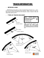
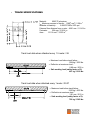
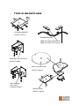
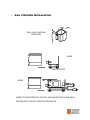
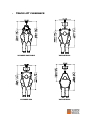
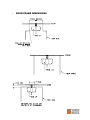
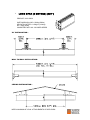
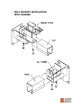
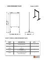
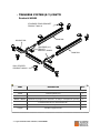
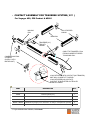
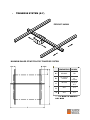
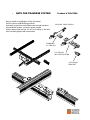
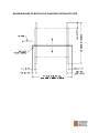
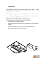
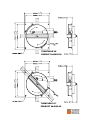
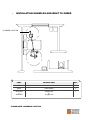
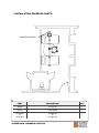
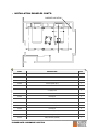
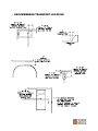
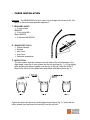
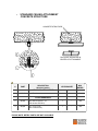
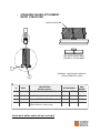
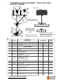
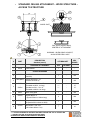
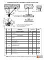
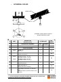
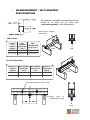
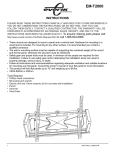
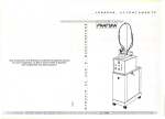
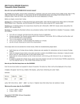
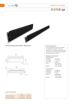
Track Installation
for
Voyager 420, 550 & 800
SAFETY INSTRUCTIONS AND WARNINGS
IMPORTANT – READ AND UNDERSTAND THESE INSTRUCTIONS. DO NOT LOSE THEM.
ALSO READ OPERATING/ INSTRUCTION CHAPTER OF THIS MANUAL BEFORE INSTALLING,
OPERATING OR SERVICING THIS EQUIPMENT
GENERAL
¾ IMPORTANT – READ THESE INSTRUCTIONS CAREFULLY OR SERIOUS INJURY MAY RESULT.
¾
KEEP THESE INSTRUCTIONS AND THE KEY PROVIDED WITH THE LIFT AT ALL TIMES.
¾
READ OPERATION AND MAINTENANCE INSTRUCTIONS IN THIS MANUAL BEFORE INSTALLING, OPERATING, OR SERVICING THIS EQUIPMENT.
¾
An authorized contractor or installer must install Voyager ceiling lifts.
¾
USE all controls and safety features only according to the rules specified in this manual.
Never attempt to force a control or button on the lift.
¾
DO NOT store the charger in a shower, bath or other areas with high humidity.
¾
DO NOT drop the patient lift or battery. Dropping the battery or lift may cause internal
damage that is not easily seen. If lift is suspected to be damaged, take to an authorized
technician for servicing.
¾
IMPORTANT: Keep all components of the lift clean and dry, and have electrical and mechanical safety checkpoints done as instructed in the Maintenance section of this manual.
¾
Replace any precautionary or instruction labels that cannot be easily read.
¾
Avoid violent shock during transportation.
LIFTING WITH THE VOYAGER
¾
YOUR LIFT is for transferring patients only. Do not use the lift for any other purpose.
¾
ALWAYS carry out the daily checklist before using the lift.
¾
Voyager ceiling lifts are intended to be used for patients within the specified weight limit indicated for the lift. Do not attempt to lift more than the weight limit indicated.
¾
Before attempting to transfer, the patient must be assessed by a qualified professional.
¾
Voyager ceiling lifts must be used by a caregiver with proper training to work with the patient
to be transferred.
¾
ONLY trained and qualified caregivers should transfer a patient. DO NOT attempt to use the
lift if you have not been properly trained to do so.
¾ ALWAYS be prepared before attempting to transfer a patient.
FOLLOW lifting procedures outlined in this manual.
SLING USAGE
¾
ONLY use Sunrise slings that are designed to fit with the Voyager
¾
ALWAYS refer to the Sling User Manual for instruction on fitting, care and maintenance
¾
DO NOT use a sling that is not recommended for the lift.
¾
NEVER use a damaged, torn or frayed sling.
¾
ALWAYS place the sling around the patient according to the instructions enclosed.
¾
Voyager ceiling lifts are specifically designed for Sunrise Voyager ceiling rail systems, slings
and accessories. Slings and accessories designed by any other manufacturer are prohibited
and will void the Voyager warranty. Use only Sunrise Medical slings and accessories to
maintain patient safety and product utility.
DO NOT use other manufacturer’s slings.
DO NOT use Sunrise slings on other manufacturer’s hoists.
¾
ELECTRICAL WARNING - SHOCK PREVENTION
¾
DO NOT touch or use a lift with bare conductors or a damaged power cord. Electrically live
equipment can electrocute a patient. If the lift or charger has any exposed or damaged wires
contact your local dealer immediately.
¾
DO NOT cut or remove the round grounding prong from any plug. All Voyager lifts are
equipped with three-prong plugs to protect from shock hazard or electrocution. Any twoprong electrical outlet must be replaced with a properly grounded three-prong outlet according to the National Electrical Code and local codes. It is the responsibility of the customer to
have the work done by a qualified electrician.
¾
DO NOT splash or expose electric parts of the device to water or moisture.
¾
CHECK nameplate for voltage and cycle requirements. These requirements differ by country.
Do not attempt to use the lift in an area that has a different voltage and cycle requirement.
¾
DO NOT attempt to expose, service or repair the lift, battery or charger. If any unit is malfunctioning, contact your local dealer.
¾
.
READ the battery and charger instructions thoroughly before using or storing them
ELECTRICAL WARNING - INSTALLATION AND
GROUNDING
¾
Electrical equipment must be installed and maintained in accordance with National Electrical
Codes.
¾
Check nameplate for voltage and cycle requirements.
In special locations i.e. bathrooms, showers or swimming pools a supplementary earth bond
must be connected at the mains supply socket. Where the Voyager Lift is supplied by a short
length of flex from an adjacent power point, the green yellow connection within the flex may
be deemed to constitute supplementary bonding. In some regions Local Authorities may
specify an additional supplementary earth to the track. This can be taken from any earth terminal on the charger end stop.
Refer to a qualified electrician who knows the latest regulations in the installation of this equipment.
¾
ELECTRICAL WARNING - SERVICE AND
MAINTENANCE
Disconnect power cord from the charger rail stopper or switch of transformer at power supply,
and unplug the battery from the lift before inspecting, adjusting or servicing the equipment. Disconnect power to equipment if it is to be left unattended or out of service.
FIRE AND EXPLOSION PREVENTION
¾
Batteries may explode, leak and cause personal injury if not disposed of properly.
•
Do not place or store the battery under direct sunlight or near a heat source
•
Do not dispose of in fire
•
Do not short the battery terminals
•
Do not incinerate
•
Flush with water if electrolyte (Acid) comes in contact with skin or eyes.
¾
Batteries must be recycled, disposed of according to local law regulations. When returning
batteries, insulate their terminals with adhesive tape, etc. Otherwise, the residual electricity
in used batteries may cause fire or explosion.
PARTS AND ACCESSORIES
Always use VOYAGER replacement parts and accessories. Using other parts and accessories
other than recommended by BHM/ SUNRISE could affect security and efficiency of the entire system. SUNRISE VOYAGER slings and patient lift accessories are specifically designed to be used
in conjunction with BHM patient transfer aids. Sling and accessories designed by other manufactures are not to be used as a component of VOYAGER patient transfer systems.
EQUIPMENT WARNING LABELS
INSPECT all precautionary labels on the equipment. Order and replace all labels that cannot be
easily read.
TRACK INFORMATION
¾
MATERIALS USED
BHM Medical’s track system, as well as it's attachment accessories, are manufactured and installed following high safety standards. BHM’s tracks are made from
high strength extruded aluminum and are bake paint coated to ensure a safe and
aesthetically pleasing profile.
¾
TYPES OF TRACKS AVAILABLE
Note:
Tracks should be
installed by accredited professionals where
prescribed by law.
2 M TRACK
PRODUCT #M0580
BHM recommends placing one
attachment per linear meter
(39 inches) of track in additional
to an attachment at the end of the
rail.
3 M TRACK
PRODUCT #M0585
90° TRACK
PRODUCT #A0170
45° TRACK
30° TRACK
PRODUCT #A0180
PRODUCT #A0175
¾
TRACK SPECIFICATIONS
q
Material :
6063-T5 aluminum
IXX Maximum moment of inertia : 1.08E6 mm4 / 2.59 in.4
Modulus of elasticity :
6.894757 MPa /10E7 psi
Extreme fiber distance from xx axis : 48.61 mm / 1.9141 in.
Perimeter:
554 mm / 21.814 in.
Area :
1311.6 mm2 / 2.033 in.2
Track load data when attached every 1.5 meter / 59
• Maximum load before track failure :
1384 kg / 3050 lbs.
• Deflection at maximum load :
8.89 mm / 0.35 in.
• Safe working load (safety factor of 3):
461 kg / 1016 lbs.
Track load data when attached every 1 meter / 39.37
• Maximum load before track failure :
2100 kg / 4625 lbs.
• Deflection at maximum load :
3.81 mm / 0.15 in.
• Safe working load (safety factor of 3):
700 kg / 1542 lbs.
¾
TYPES OF BRACKETS USED
STANDARD BRACKET
PRODUCT #A0110
REVERSE BRACKET
PRODUCT #A0562 (RIGHT-LEFT)
PRODUCT #A0561 (LEFT-RIGHT)
STANDARD WALL BRACKET
PRODUCT #A4900
METAL CEILING PLATE
PRODUCT #A0557
WALL BRACKET
WITH PIVOT
PRODUCT #A4950
BRACKET SHIM
PRODUCT #A0563
¾
RAIL STOPPERS INSTALLATION
DRILL RAIL HOLES AS
INDICATED
A5320
END STOPPER
A5300
INSERT THE STOPPERS IN THE RAIL AND INSURE BOLTS ARE SNUG.
PLEASE NOTE: DO NOT OVER TIGHTEN BOLTS
¾
TRACK LIFT CLEARANCE
VOYAGER PORTABLE
VOYAGER 420
VOYAGER 550
VOYAGER 800
¾
DOOR FRAME DIMENSIONS
¾
LONG SPAN (6 METERS) (236”)
PRODUCT # 201.00550
SAFE WORKING LOAD = 250Kg (550lbs)
WEIGHT BY METER = 6.22Kg/m (4.1lbs/p)
6m = 37Kg (81lbs)
COMPATIBLE WITH ALL VOYAGER SERIES
X-Y INSTALLATION :
WALL TO WALL INSTALLATION :
CEILING INSTALLATION :
NEED A MINIMUM OF 2 RAIL ATTACHEMENTS AT BOTH ENDS
¾
WALL BRACKET INSTALLATION
WALL BRACKET
SWIVEL WALL BRACKET
PRODUCT #A4900
PRODUCT #A4950
TYPICAL INSTALLATION
WALL BRACKET WITH
WOOD STRUCTURE
NB: Must be fix on 2 studs (2 X 4)
WALL BRACKET WITH
CONCRETE STRUCTURE
¾
WALL BRACKET INSTALLATION
WITH CHARGER
¾
SEMI-PERMANENT RACK
Product # A9200
2 OR 3 METER TRACK
HOW TO ORDER A SEMI-PERMANENT RACK:
PART
DESCRIPTION
QTY
A9200
Semi Permanent rack
1
M0580
or
M0585
2 meter rail
or
3 meter rail
1
A5320
Rail Stopper
(only for Portable Voyager)
2
E7520
3 meter power cord
(only for Voyager 420 or 550)
(North American plug)
1
1
¾
TRAVERSE SYSTEM (X-Y) CONT’D
Product # A5800
STANDARD TRACK BRACKET
PRODUCT #A0110
MAIN RAIL
MOVING RAIL
TRAVERSE (X-Y)
TROLLEY
PRODUCT #A5800
MAIN RAIL
RAIL STOPPER
PRODUCT #A5320
PART
DESCRIPTION
QTY
PORTABLE VOYAGER
A5800
Traverse system (X-Y)
1
A5320
Rail Stopper
6
M0580 or M0585
Parallel rail any length (2 or 3 meter rails – as many in a sequence as you like)
2
M0580 or M0585
2 meter traverse rail or 3 meter traverse rail *
1
A5900
Trolley
1
Voyager
Portable Voyager track lift
1
* = if you need more than 3 meters, contact BHM
¾
CONTACT ASSEMBLY FOR TRAVERSE SYSTEM ( X-Y )
For Voyager 420, 550 Product # A5810
MOVING
RAIL
RAIL STOPPER
#A5320
MAIN RAIL
TRAVERSE (X-Y)
TROLLEY
#A5800
CABLE TO TRANSFER 27Vac
FROM CHARGER STOPPER
TO MOVING RAIL.
CHARGER AND RAIL
STOPPER
(SUPPLY WITH
MOTOR UNIT)
-LONG STOPPER WITH CONTACT (NO TRANSFO).
UNIT WILL CHARGE AT THIS END.
-LONG STOPPER (NO CONTACT).
-CONTACT PCB (RIVETED ON TROLLEY
PRODUCT #A5810
PART
DESCRIPTION
QTY
VOYAGER 420 OR 550 OR 800
A5800
Traverse system (X-Y)
1
A5320
Rail stopper
2
A5810
Contact assembly for Traverse system (X-Y)
1
M0580 or M0585
Parallel rail any length (2 or 3 meter rails – as many in a sequence as you like)
2
M0580 or M0585
2 meter traverse rail or 3 meter traverse rail *
1
* = if you need more than 3 meters, contact BHM
¾
TRAVERSE SYSTEM (X-Y)
PRODUCT #A5800
MAXIMUM RANGE OF MOTION FOR TRAVERSE SYSTEM
CENTIMETRES
INCHES
A**
300 MAX.
118
B*
AS LONG AS
DESIRED.
AS LONG
AS
DESIRED.
30 to 40
12.5V to
15.7
D
28.5
11.2
E
44.5
17.5
C
** = IF MORE IS NEEDED…
CALL BHM
¾
GATE FOR TRAVERSE SYSTEM
Easy to install no modification to the rail needed.
Can be used on all BHM lifting products.
Automatic system that works without any manual activation.
All mechanical system, no electric power needed.
Safety feature that prevent the lift from falling in the rails
aren’t perfectly aligned with one another.
Product # 700.07500
700.07500 - WHAT’S INCLU-
STANDARD
X-Y TROLLEY
X-Y TROLLEY
WITH GATE SYSTEM
ACTIVATION
BRACKET
MAXIMUM RANGE OF MOTION FOR TRAVERSE SYSTEM WITH GATE
¾
TURNTABLE
The BHM Medical Turntable is a first class track junction system. Adding
flexibility to the design, its main application is to provide access to two or more rooms while
providing a continuous track path.
The turntable action is done by an electric, soft and low noise actuator mounted
on the unit. The turning action is commanded by pulling once on a simple cord. Rotation will start, automatically come to a stop and lock at the end of its
rotation,
ready to turn back to its original position on demand.
IMPORTANT FACTS TO REMEMBER ON THE TURNTABLE
+
The turntable is only available motorized
+
An electrical outlet must be found close to the installation to accommodate the
turntable
+
The return to charge function on our track lifts must be disconnected.
+
Re-enforcement required to install the turntable
TURNTABLE 90°
PRODUCT #A4000-90
TURNTABLE 45°
PRODUCT #A4000-45
¾
INSTALLATION EXAMPLES AND WHAT TO ORDER
CHARGER LOCATION
PART
DESCRIPTION
QTY
M0585
3 meter rail
1
A0110
Track bracket
4
ALB3-4FB
or
ALB2-4FB
Voyager 420
or
Voyager 550
1
PLEASE NOTE: HARDWARE IS EXTRA
¾
INSTALLATION EXAMPLES CONT’D
PART
DESCRIPTION
QTY
M0580
2 meter rail
1
A0110
Track bracket
6
A0170
90° rail
1
Voyager
Portable Voyager
1
A5900
Standard trolley
2
A5320
End stopper
4
A8300
Arm extension (optional)
1
E0090
Handset (optional)
1
A3710
Strap extension (optional)
1
PLEASE NOTE: HARDWARE IS EXTRA
¾
INSTALLATION EXAMPLES CONT’D
CHARGER LOCATION
PART
DESCRIPTION
QTY
M0580
2 meter rail
2
A0110
Track bracket
5
ALB3-4FB
or
ALB2-4FB
Voyager 420
or
Voyager 550
1
PLEASE NOTE: HARDWARE IS EXTRA
¾
INSTALLATION EXAMPLES CONT’D
CHARGER LOCATION
PART
DESCRIPTION
QTY
M0580
2 meter rail
2
M0585
3 meter rail
3
A0110
Track bracket
12
A5800
Traverse system (X-Y)
1
+ FOR VOYAGER 420 OR 550
Voyager 420
or Voyager 550
1
A5810
Contact kit
1
A5320
End stopper
2
+ FOR PORTABLE VOYAGER
Portable Voyager
1
A5900
Standard trolley
1
A5320
End stopper
6
A8300
Arm extension (optional)
1
E0090
Handset (optional)
1
A3710
Strap extension (optional)
1
PLEASE NOTE: HARDWARE IS EXTRA
¾
RECOMMENDED TRANSFERT LOCATION
¾
CURVE INSTALLATION
PURPOSE:
The BHM A0590 joint kit is used to join straight rail and curve rail. Our
goal is to insure the best possible alignment.
1. REQUIRED PARTS.
Ö 2 union plates
#M0590P
Ö 2 hex. bolts M6 x
80mm #Q3235
Ö 2 locknuts M6 #Q3410
2. SUGGESTED TOOLS.
Ö
Ö
Ö
Ö
Ö
Plastic hammer
Ratchet
key 10mm
box 10mm
flat blade screwdriver
3. INSTRUCTION.
The union plates must be centered on both sides of the rail attachment. At a
slight angle, insert the 2 union plates into the rail opening (fig. 1). Lift up slightly
while pressing the plates together over the top of the rail. Insert the 2 M6 X
80mm bolts into the union plate holes and attach with M6 locknuts (fig. 2).
Tighten the bolts until joints are solidly aligned and secure (fig. 3). Verify that the
trolley wheels turn freely and roll smoothly over the rail joint.
¾
STANDARD CEILING ATTACHMENT
CONCRETE STRUCTURE
CONCRETE STRUCTURE
RAIL JOINT SHOULD BE IN
CENTER OF ATTACHMENT
#
PART
DESCRIPTION
Standard (metric)
STANDARD ATTACHMENT
1
A0110
Track Bracket
QTY/BRACKET
MIN.
ORDER
STD
LATERAL
1
-
-
OTHER HARDWARE
2
Q0423
-
Hilti anchor HDI 3/8 – 16
(Hilti anchor HDI M10)
1
-
100
3
Q0350
-
3/8 – 16 x 1" hex.
(M10 x 25mm hex.)
1
-
100
PLEASE NOTE: METRIC PARTS ARE NOT AVAILABLE
¾
STANDARD CEILING ATTACHMENT
WOOD STRUCTURE
WOOD STRUCTURE
RAIL JOINT SHOULD BE IN
CENTER OF ATTACHMENT
WARNING: WHEN USING LAG-BOLT;
ALWAYS PRE-DRILL HOLE
#
PART
DESCRIPTION
Standard (metric)
STANDARD ATTACHMENT
1
A0110
Track Bracket
QTY/BRACKET
MIN.
ORDER
STD
LATERAL
1
-
-
1
-
100
OTHER HARDWARE
2
Q0740
-
Lag bolt Ø3/8" x 4"
(Lag bolt Ø10mm x 100mm long)
PLEASE NOTE: METRIC PARTS ARE NOT AVAILABLE
¾
STANDARD CEILING ATTACHMENT
WOOD STRUCTURE – NO ACCESS TO STRUCTURE
WOOD JOIST
RAIL JOINT SHOULD BE IN
CENTER OF ATTACHMENT
WARNING: WHEN USING LAG-BOLT;
ALWAYS PRE-DRILL HOLE
#
DESCRIPTION
Standard (metric)
PART
STANDARD ATTACHMENT
1
A0110
Track bracket
QTY/BRACKET
MIN.
ORDER
STD
LATERAL
1
-
-
OTHER HARDWARE
2
Q0350
-
3/8 – 16 x 1" hex.
(M10 x 25mm hex.)
1
-
100
3
Q0740
-
Lag bolt Ø3/8 x 4"
(Lag boltØ10mm x 100mm long)
2
-
100
4
Q0426
-
Hilti unistrut nut 3/8 – 16
(Hilti unistrut nut M10)
1
-
100
5
Q1230
-
Hilti unistrut 1 5/8" x 10’
(Hilti unistrut 40mm x 3m)
**
-
10
** = REFER TO STEEL SPAN SPECIFICATIONS SHEET
PLEASE NOTE: METRIC PARTS ARE NOT AVAILABLE
SUSPENDED CEILING ATTACHMENT – WOOD STRUCTURE –
UNISTRUT SPANNED
¾
WOOD JOIST
SUSPENDED CEILING DRYWALL OR ACOUSTIC TILE
WARNING: WHEN
USING LAG-BOLT;
ALWAYS PRE-DRILL
HOLE
RAIL JOINT SHOULD BE IN
CENTER OF ATTACHMENT
#
DESCRIPTION
Standard (metric)
PART
STANDARD ATTACHMENT
1
A0110
* = LATERAL SUPPORT MAY BE
REQUIRED IN SOME INSTANCES
DEPENDING ON THE DROP
CEILING MEASUREMENTS
QTY/BRACKET
MIN.
ORDER
STD
LATERAL
1
-
-
Nut 3/8 – 16
(Nut M10)
2
4
100
Locknut stover 3/8 – 16
(Locknut stover M10)
1
-
100
2
-
100
***
***
***
***
15
15
Track Bracket
OTHER HARDWARE
3
Q0405
-
2
000.00402
-
4
Q0740
-
Lag bolt Ø3/8 x 4"
(Lag bolt Ø10mm x 100mm long)
5
Q0393
Q0394
-
Threaded rod 3/8 – 16 x 36"
Threaded rod M10 x 1m long)
Threaded rod 3/8 – 16 x 10'
(Threaded rod M10, 3m long)
6
A0553
Lateral bracket
-
2
10
7
A0557
Metal ceiling plate
1
-
100
8
Q0424
-
Suspended hilti strut nut 3/8
(Suspended hilti strut nut M10)
1
1
100
9
Q0426
-
Hilti unistrut nut 3/8 – 16
(Hilti anchor HDI M10)
-
1
100
10
Q1230
-
Hilti unistrut 1 5/8" X 10'
(Hilti unistrut 40mm x 3 m)
**
-
10
11
Q0350
-
3/8 – 16 x 1" hex.
(M10 x 25mm hex)
-
1
100
*** = LENGTH DEPENDS ON DISTANCE BETWEEN CEILING AND TOP OF STRUCTURE
** = REFER TO STEEL SPAN SPECIFICATIONS SHEET
PLEASE NOTE: METRIC PARTS ARE NOT AVAILABLE
¾
STANDARD CEILING ATTACHMENT – WOOD STRUCTURE –
ACCESS TO STRUCTURE
WOOD JOIST
RAIL JOINT SHOULD BE IN
CENTER OF ATTACHMENT
WARNING: WHEN USING LAG-BOLT;
ALWAYS PRE-DRILL HOLE
#
DESCRIPTION
Standard (metric)
PART
STANDARD ATTACHMENT
1
A0110
QTY/BRACKET
MIN.
ORDER
STD
LATERAL
1
-
-
Nut 3/8 – 16
(Nut M10)
1
-
100
Locknut stover 3/8 – 16
(Locknut stover M10)
1
-
100
Track Bracket
OTHER HARDWARE
2
Q0405
-
3
000.00402
-
4
Q0393
Q0394
-
Threaded rod 3/8 – 16 x 36"
(Threaded rod M10, 1m long)
Threaded rod 3/8 – 16 x 10'
(Threaded rod M10 x 3m long)
***
***
-
15
15
5
A0557
Metal ceiling plate
1
-
100
6
Q0740
-
Lag bolt Ø3/8 x 4"
(Lag bolt Ø10mm x 100mm long)
2
-
100
7
Q0424
-
Suspended hilti unistrut nut 3/8 – 16
(Suspended hilti unistrut nut M10)
1
8
Q1230
-
Hilti unistrut 1 5/8" X 10'
(Hilti unistrut 40mm x 3m)
**
*** = LENGTH DEPENDS ON DISTANCE BETWEEN CEILING AND TOP OF STRUCTURE
** = REFER TO STEEL SPAN SPECIFICATIONS SHEET
PLEASE NOTE: METRIC PARTS ARE NOT AVAILABLE
100
-
10
SUSPENDED CEILING ATTACHMENT CONCRETE STRUCTURE
¾
CONCRETE STRUCTURE
PRE-CAST HOLLOW CORE
SUSPENDED CEILING
DRYWALL OR ACOUSTIC
TILE
RAIL JOINT SHOULD BE IN
CENTER OF ATTACHMENT
* = LATERAL SUPPORT MAY BE REQUIRED IN SOME
INSTANCES DEPENDING ON THE DROP
CEILING MEASUREMENTS
#
DESCRIPTION
Standard (metric)
PART
STANDARD ATTACHMENT
1
A0110
QTY/BRACKET
MIN.
ORDER
STD
LATERAL
1
-
-
Nut 3/8 – 16
(Nut M10)
2
4
100
Locknut stover 3/8 – 16
(Locknut stover M10)
1
-
100
1
1
100
***
***
***
***
15
15
Track Bracket
OTHER HARDWARE
2
Q0405
-
3
000.00402
-
4
Q0423
-
Hilti anchor HDI 3/8 – 16
(Hilti anchor HDI M10)
5
Q0393
Q0394
-
Threaded rod 3/8 – 16 x 36"
(Threaded rod M10, 1m long)
Threaded rod 3/8 – 16 x 10'
(Threaded rod M10, 3m long)
6
A0553
Lateral Bracket
-
2
10
7
A0557
Metal ceiling plate
1
-
100
8
Q0350
-
3/8 – 16 x 1" hex.
(M10 x 25mm hex.)
-
1
100
9
Q0427
-
Hilti anchor HDI-P 3/8
(Hilti anchor HDI-P M10)
1
1
100
*** = LENGTH DEPENDS ON DISTANCE BETWEEN CEILING AND TOP OF STRUCTURE
¾
SUSPENDED CEILING ATTACHMENT – STEEL STRUCTURE
STEEL STRUCTURE
SUSPENDED CEILING DRYWALL OR ACOUSTIC TILE
RAIL JOINT SHOULD BE IN CENTER
OF ATTACHMENT
* = LATERAL SUPPORT MAY BE REQUIRED IN SOME
INSTANCES DEPENDING ON THE DROP
CEILING MEASUREMENTS
#
DESCRIPTION
Standard (metric)
PART
STANDARD ATTACHMENT
1
A0110
QTY/BRACKET
MIN.
ORDER
STD
LATERAL
1
-
-
Nut 3/8 – 16
(Nut M10)
1
4
100
Locknut stover 3/8 – 16
(Locknut stover M10)
1
-
100
-
1
100
***
***
***
***
15
15
Track Bracket
OTHER HARDWARE
2
Q0405
-
3
000.00402
-
4
Q0350
-
3/8 – 16 x 1" hex.
(M10 x 25mm hex.)
5
Q0393
Q0394
-
Threaded rod 3/8 – 16 x 36"
(Threaded rod M10, 1m long)
Threaded rod 3/8 – 16 x 10'
(Threaded rod M10 x 3m long)
6
A0553
Lateral Bracket
-
2
10
7
A0557
Metal ceiling plate
1
-
100
8
Q0424
-
Suspended hilti unistrut nut 3/8 – 16
(Suspended hilti unistrut nut M10)
1
1
100
9
Q0426
-
Hilti unistrut nut 3/8 – 16
(Hilti unistrut nut M10)
-
1
100
10
Q1230
-
Hilti unistrut 1 5/8" X 10'
(Hilti unistrut 40mm x 3m)
**
-
10
*** = LENGTH DEPENDS ON DISTANCE BETWEEN CEILING AND TOP OF STRUCTURE
** = REFER TO STEEL SPAN SPECIFICATIONS SHEET
¾
CATHEDRAL CEILING
WOOD JOIST
4X4
WARNING: WHEN USING LAG-BOLT;
ALWAYS PRE-DRILL HOLE
#
DESCRIPTION
Standard (metric)
PART
STANDARD ATTACHMENT
1
A0110
QTY/BRACKET
MIN.
ORDER
STD
LATERAL
1
-
-
Nut 3/8 – 16
(Nut M10)
1
-
100
Locknut stover 3/8 – 16
(Locknut stover M10)
1
-
100
Threaded rod 3/8 – 16 x 36"
(Threaded rod M10, 1m long)
Threaded rod 3/8 – 16 x 10'
(Threaded rod M10 x 3m long)
***
***
-
15
15
Track Bracket
OTHER HARDWARE
2
Q0405
-
3
000.00402
-
4
Q0393
Q0394
-
5
-
Coupling nut 3/8 – 16
(Coupling nut M10)
1
-
100
6
-
Dowel screw 3/8 x 4”
(Dowel screw M10 x 100mm)
1
-
100
7
-
Lag bolt Ø3/8 x (minimum 2” in the structure)
(Lag bolt Ø10mm x (minimum 50mm in the
structure)
1
-
100
*** = LENGTH DEPENDS ON DISTANCE BETWEEN CEILING AND TOP OF STRUCTURE
PLEASE NOTE: METRIC PARTS ARE NOT AVAILABLE
¾
RE-ENFORCEMENT – HILTI UNISTRUT
SPECIFICATIONS
The maximum allowable loads specified below
should be at least two (2) times the
« safe working load » of the lifting device.
Span fixed on supports
at both ends
SIMPLE SPAN:
Distance
«D»
between
supports
Max.
allowable
load at span
centre
Max.
allowable load
at 1/3 of « D »
24 in. (610mm)
431 kg (950 lbs.)
647 kg (1425 lbs.)
36 in. (914 mm)
290 kg (640 lbs.)
436 kg (960 lbs.)
Load
Load
BACK TO BACK SPAN:
Distance « D »
between
supports
Max. allowable
load at span
centre
Max. allowable
load at 1/3 of
«D»
Distance « J »
between span
jointing
48 in. (1250 mm)
590 kg (1300 lbs.)
885 kg (1950 lbs.)
16 in. (406mm)
72 in. (1830 mm)
395 kg (870 lbs.)
592 kg (1305 lbs.)
24 inc. (610 mm)
Load
Joint span with two (2) 3/8 in. bolts
Span
fixed
on
supports at both ends
Load