1
TAINET
Network Series Modem
T-288C/T-1496terbo/T-1496/ITM3296bis
USER'S MANUAL
The Professional Partner
TAINET COMMUNICATION SYSTEM CORP.
V1.7
Headquarters:
Beijing Branch:
No. 25, Alley 15, Lane 120,
Sec. 1. Nei-Hu Rd,
Taipei 114, Taiwan
TEL: 886-2-26583000
FAX: 886-2-26583232
3F, A Building, 113 Zhi Chun Lu,
HaiDian District, Beijing, China
Zip Code: 100086
TEL: 86-10-62522081~87
FAX: 86- 10-62522077
07008-00010
2004/03/24
CONTENTS
CHAPTER 1
1.1
1.2
1.3
CHAPTER 2
2.1
2.2
2.3
2.4
2.5
2.6
2.7
CHAPTER 3
3.1
3.2
3.3
3.4
3.5
CHAPTER 4
4.1
4.2
4.3
4.4
4.5
4.6
4.7
4.8
4.9
4.10
4.11
THE TAINET NETWORK SERIES MODEM
Description
Technical Specifications
Ordering Information
INSTALLATION
Description
Unpacking
Site Requirements
Site Selection
AC Electrical Outlet Connection
Connecting With Dial Line
Connecting With Leased Line
FRONT PANEL LCD AND MENU-DRIVEN
The Front Panel Description
The Rear Panel Description
Operating The TAINET Network Series Modem
The Menu Tree
Detailed Description of The Menu Tree
GENERAL INFORMATION AND FEATURES
Preview
Dial Line VS. Leased Line
2W / 4W Leased Line
Originate Mode VS. Answer Mode
Synchronous VS. Asynchronous
Error Correction And Data Compression
Configuration Profile Set-up
Remote Access
Multi-standard Handshake
Auto Fallback and Fall Forward
Auto Dial Back-up
4.12
CHAPTER 4
4.13
4.14
4.15
4.16
4.17
4.18
4.19
Auto Call Back Security
GENERAL INFORMATION AND FEATURES
Line Status Monitoring
B.E.R. Test
Intelligent Dial And Redial
Front Panel Lock And Password
ITU-T V.13 and Pseudo, Simulated carrier control in half
duplex
G3 Fax Send/Receive
Symbol Rate Selection
CHAPTER 5
INSTRUCTION SETS
5.1
5.2
5.3
5.4
AT Command Set
Dial Modifiers
Result Codes
V.25bis Auto Call Unit
CHAPTER 6
6.1
6.2
6.3
6.4
6.5
6.6
MAINTENANCE
Description
Instruments
Self test
Periodic Maintenance
Troubleshooting
Return Procedure
APPENDIX 1
S-REGISTER TABLE FOR T-288C & ITM-3296bis
APPENDIX 2
S-REGISTER TABLE FOR T-1496 & T-1496terbo
APPENDIX 3
AUXILIARY SUMMARY FOR FAX FUNCTION
APPENDIX 4
T-288C/ITM-3296bis LCD MENU QUICK REFERENCE
APPENDIX 5
T-1496/T-1496terbo LCD MENU QUICK REFERENCE
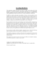
FCC REQUIREMENTS
This equipment complies with Part 68 of the FCC Rules. On the base unit of this
equipment is a label that contains, among other information, the FCC Registration
Number and Ringer Equivalence Number (REN) for this equipment. IF REQUESTED,
THIS INFORMATION MUST BE GIVEN TO THE TELEPHONE COMPANY.
The REN is useful to determine the quantity of devices you may connect to your
telephone line and still have all of those devices ring when your telephone number is
called. In most, but not all areas, the sum of the REN's of all devices connected to one
line should not exceed five (5.0). To be certain of the number of devices you may
connect to your line, as determined by the REN you should contact your local
telephone company to determine the maximum REN to your calling area.
If your equipment causes harm to the telephone network, the telephone company may
discontinue your service temporarily. If possible, they will notify you in advance. But
the advance notice isn't practical, you will be notified as soon as possible. You will be
informed of your right to file a complaint with the FCC. Your telephone company
may make changes in its facilities, equipment, operations or procedures that could
affect the proper functioning of your equipment. If they do, you will be notified in
advance to give you an opportunity to maintain uninterrupted telephone service.
If you experience trouble with this telephone equipment, please contact the following
address and phone number for information on obtaining service or repairs.
The telephone company may ask that you disconnect this equipment from the network
until the problem has been corrected or until you are sure that the equipment is not
malfunctioning.
This equipment may not be used on coin service provided by the telephone company.
Connection to party lines is subject to state tariffs.
COMPANY: SUMMIT MICRO DESIGN, INC.
ADDRESS: 485 MACARA AVE., SUITE 901 SUNNYVALE, CA 94086 USA
TEL NO: (408)739-6348
INFORMATION TO THE USER
NOTE: This equipment has been tested and found to comply with the limits for a
Class A digital device. Pursuant to Part 15 of the FCC Rules. These limits are
designed to provide reasonable protection against harmful interference in a residential
installation. This equipment generates, uses and if not installed and used in
accordance with the instructions may cause harmful interference will not occur in a
particular installation. If this equipment does cause harmful interference to radio or
television reception, which can be determined by turning the equipment off and on.
The user is encouraged to try to correct the interference by one or more of the
following measures:
Reorient or relocate the receiving antenna.
Increase the separation between the equipment and receiver.
Connect the equipment into an outlet on a circuit different from that to which the
receiver is connected.
Consult the dealer or an experienced radio/TV technician for help.
This booklet is available from the US government Printing Office, Washington, DC
20402, Stock NO. 004-000-00345-4.
The shielded RS-232 cable is to be used in order to ensure compliance with FCC Part
15, and it is the responsibility of the user to provide and use shielded RS-232 cable
from MODEM to personal computer.
CAUTION: Any changes of modifications not expressly approved by the grantee of
this device could void the user's authority to operate the equipment.
Notice
The information in this User’s Manual is subject to change without
notice.
TAINET COMMUNICATION SYSTEM CORP. MAKE NO WARRANTY OF
ANY KIND WITH REGARD TO THIS MATERIAL, INCLUDING, BUT NOT
LIMITED TO, THE IMPLIED WARRANTIES OF MERCHANTABILITY AND
FITNESS FOR A PARTICULAR PURPOSE.
Tainet Communication System Corp. shall not be liable for errors
contained herein or for incidental consequential damages in connection
with the furnishing, performance, or use of this material.
This User’s Manual contains proprietary information which is
protected by copyright. All rights are reserved. No part of this User’s
Manual may be photocopied, reproduced, or translated into another
language without prior written consent of Tainet Communication
System Corp.
Copyright 1995 by TAINET COMMUNICATION SYSTEM CORP.
Microsoft is a registered trademark of Microsoft Corportation.
MS-DOS is a registered trademark of Microsoft Corportation.
Hayes is a registered trademark of Hayes Microcomputer Products, Inc.
MNP is a registered trademark of Microcom, Inc.
IBM is a registered trademark of International Business Machines.
CHAPTER 1
TAINET NETWORK SERIES MODEM
CONTENT
1.1 Description
1.2 Technical Specifications
1.3 Ordering Information
TAINET NETWORK SERIES MODEM
1-1
CHAPTER 1 : THE TAINET NETWORK SERIES MODEM
1.1 Description
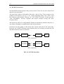
• The TAINET Network Series Modem included T-288C, T-1496terbo, T-1496,
and ITM-3296bis, is a high performance, synchronous and asynchronous, full
duplex multi-standard modem. It is designed for use on 2-wire dial circuits and 2/4wire leased lines.
The TAINET Network Series Modem fully comply with ITU-T V.34
recommendation (up to 33.6kbps) as well as being compatible with ITU-T
Recommendations V.32bis/V.32, V.33, V.29, V.27bis, V.26, V.22bis, V.22, V.23
and V.21 international standards, operating at speeds of 14400, 12000, 9600, 7200,
4800, 2400, 1200, 600 and 300bits per second (depend on each model).
In V.34 and V.32bis/ V.32 modes, echo concellation provides 2-wire full duplex
operation over all PSTN circuits including those with satellite sections.
Compatibility is also provided with Bell 212A and Bell 103 operating standard.
• V.34 mode providing full duplex operation at up to 28.8 kbps (33.6/31.2kbps at
proprietary mode) with line probing, symbol rate and carrier frequency selection
(for T-288C only).
• A range of performance enhancing techniques are available for V.34 mode,
including Adaptive Precoding, Non-Linear Encoding (Warping), Constellation
Expansion, Multidimensional Trellis coding and Shell Mapping (for T-288C only).
• A 2 by 16 characters LCD display with back lighted control for configuration setup and monitoring conveniently.
• There are 10 factory default profiles and 10 user's profiles of your easiest
configuration setting.
• Line status monitoring including transmitted/received signal level, S/N ratio, signal
quality, frequency shift, delay, echo, retrain count, Tx/Rx baud rate, Tx/Rx
frequency, ..., etc.
•
•
•
•
•
•
•
•
V.13 simulated carrier control & pseudo HDX control for half duplex application.
Automatic dial Back-up and restore with menu or auto.
Front panel lock features prevents from the operation of unauthorized person.
Remote configuration & status by secondary channel.
Password call back security.
Network Management System available.
16 modem cards rack shelf available.
Tx power back-off comply V.34 power reduction recommendation.
1-2
TAINET NETWORK SERIES MODEM
1.2 Technical Specifications
The T-288C fully comply with ITU-T recommendations V.34, V.33, V.32bis, V.32,
V.22bis, V.22, V.21, V.23, V.29, V.27bis, V.26, V.24, V.28, V.25, V.25bis, V.52,
V.54, V.42, V.42bis, V.8, and BELL 212A/103 operating standards.
The T-1496terbo fully comply with V.32 terbo and ITU-T recommendations V.32bis,
V.32, V.22bis, V.22, V.21, V.23, V.24, V.28, V.25bis, V.52, V.54, V.42, V.42bis, and
BELL 212A/103 operating standards.
The T-1496 fully comply with ITU-T recommendations V.32bis, V.32, V.22bis, V.22,
V.21, V.23, V.24, V.28, V.25bis, V.52, V.54, V.42, V.42bis, and BELL 212A/103
operating standards.
The ITM-3296bis fully comply with ITU-T recommendations V.33, V.32bis, V.32,
V.22bis, V.22, V.21, V.23, V.29, V.27bis, V.26, V.24, V.28, V.25bis, V.52, V.54,
V.42, V.42bis, and BELL 212A/103 operating standards.
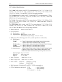
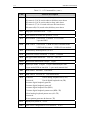
• Modem Protocol
: Please refer to table 1-1.
• Clock Tolerance
(1) Synchronous : ± 0.01%
(2) Asynchronous : Basic range + 1% to - 2.5%
Extended overspeed range + 2.3% to - 2.5%
• DTE Speed (The following speed with (*) mark depends on each model.)
(1) Synchronous :
T-288C
33600/31200/28800/26400/24000/21600/19200/16800
/14400/12000/9600/7200/4800/2400/1200 bps
T-1496 terbo
19200/16800/14400/12000/9600/7200/4800/2400/1200 bps
T-1496
14400/12000/9600/7200/4800/2400/1200 bps
ITM3296 bis
14400/12000/9600/7200/4800/2400/1200 bps
(2) Asynchronous: 115200/76800/57600/38400/*33600/*31200/*28800/*26400
/*24000/*21600/19200/*16800/14400/12000/9600/7200
/4800/3600/2400/1200/600/300 bps with speed conversion.
Total bit length : 8, 9, 10, 11 bits
Parity bit
: odd, even, none
Stop bit
: 1, 1.5, 2 bits
• Error Correction
: MNP 4/ITU-T V.42
• Data Compression : MNP 5/ITU-T V.42bis
• Flow Control
: Hardware
Software
CTS/RTS, CTS only
X-ON/X-OFF
• Dial Command : Extended AT and ITU-T V.25bis command set.
• G3 Fax Modulation and speed : V.29
-- 9600, 7200 bps
V.27ter
-- 4800, 2400 bps
V.21 channel 2 -- 300 bps
TAINET NETWORK SERIES MODEM
1-3
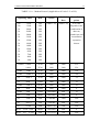
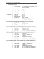
TABLE 1-1A : Modem Protocol (Applicable to 4/2 wire L-L or D-L)
Operating Mode
Mod.
Carrier
Symbol
Rate
Constellation
points
V.34+
V.34+
V.34
V.34
V.34
V.34
V.34
V.34
V.34
V.34
V.34
V.34
V.34
V.34
33600
31200
28800
26400
24000
21600
19200
16800
14400
12000
9600
7200
4800
2400
SM
SM
SM
SM
SM
SM
SM
SM
SM
SM
SM
SM
SM
SM
(Table 1-1c)
(Table 1-1c)
4 to 1024
Depends on the
combination of
data rate,
symbol rate and
constellation
expansion
chosen.
V.32terbo
19200
TCM
1800
2400
512
16800
TCM
1800
2400
256
V.32bis
14400 T
TCM
1800
2400
128
V.32bis
12000 T
TCM
1800
2400
64
V.32
9600 T
TCM
1800
2400
32
V.32
9600
QAM
1800
2400
16
V.32bis
7200 T
TCM
1800
2400
16
V.32
4800
QAM
1800
2400
4
V.22bis
2400
QAM
1200/2400
600
16
V.22
1200
DPSK
1200/2400
600
4
V.23
1200/75
FSK
1700/420
1200
N/A
V.23
600/75
FSK
1500/420
600
N/A
V.21
0-300
FSK
1080/1750
300
N/A
BELL
212A 1200
DPSK
1200/2400
600
4
BELL
103
FSK
1175/2125
300
N/A
0-300
1-4
TAINET NETWORK SERIES MODEM
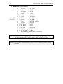
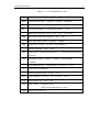
TABLE 1-1B : Modem Protocol (Applicable to 4 wire L-L)
Operating Mode
Mod.
Carrier
Symbol
Rate
Constellation
points
V.33
14400 T
TCM
1800
2400
128
V.33
12000 T
TCM
1800
2400
64
V.33
9600 T
TCM
1800
2400
32
V.33
7200 T
TCM
1800
2400
16
V.33
4800
QAM
1800
2400
4
V.29
9600
QAM
1700
2400
16
V.29
7200
QAM
1700
2400
8
V.29
4800
DPSK
1700
2400
4
V.27 bis
4800
DPSK
1800
1600
8
V.27 bis
2400
DPSK
1800
1200
4
V.26
2400
DPSK
1800
1200
4
V.26
1200
DPSK
1800
1200
2
V.23
1200
FSK
1700
1200
N/A
V.23
600
FSK
1500
600
N/A
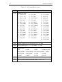
Notes: TCM : Trellis Code Modulation
QAM : Quadrature Amplitude Modulation.
DPSK : Differential Phase Shift Keying.
FSK
: Frequency Shift Keying.
SM
: Shell Mapping with 4 Dimensional Trellis Coded Modulation
TABLE 1-1C : V.34 Symbol Rate and Carrier Frequency
Symbol Rate (Baud)
Low Carrier (Hz)
High Carrier (Hz)
2400
1600
1800
2743
1646
1829
3000
1800
2000
3200
1829
1920
3429
1959
1959
TAINET NETWORK SERIES MODEM
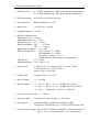
• Transmit Level
1-5
: 0~-31 dBm adjustable by 1 dB step for leased-line application.
0~-15 dBm adjustable by 1 dB step for dial-line application.
• Line Requirement : 4/2 wire Leased Line & Dial Line
• Line Impedance
: Balanced 600 ohms ± 10 %
• Return Loss
: > 24 dB, 300 - 3400 Hz
• Longitude Balance : > 60 dB
• Dial Line Characteristics:
Maximum Current : 120 mA
Holding Resistance : 50 ~ 220 Ω
Holding Current : 20 ~ 110 mA
Ring Detect Range : ON - > 27 Vrms
OFF - < 13 Vrms
Ring Detect Frequency: 16 - 50 Hz
DTMF Characteristics:
O/P Lowband -8 ± 1 dBm
O/P Highband -6 ± 1 dBm
Frequency Tolerance ≤ ± 1 %
TONE Duration and Spacing 72 ms (adjustable)
Pulse Per Sec
: 10 ± 0.5 PPS
Make/Break Ratio : 33/67, 39/61 ± 3 %
• Auto Answer
: V.32bis/V.32/V.22 Comply to ITU-T V.25 & V.25bis
V.34 meets ITU-T V.8, V.25/V.25bis
Answer Tone: 2100±15Hz
• Calling Tone
: Comply to ITU-T V.8, V.25
• Receive Range
: +3 ~ -43 dBm
• Dynamic Range
: +3 ~ -26/+3 ~ -40/-6 ~ -33/-6 ~ -43 dBm (for T-288C)
+3 ~ -26/+3 ~ -40/-6 ~ -33/-6 ~ -43 dBm (for ITM-3296bis)
+4 ~ -33/-4 ~ -43dBm (for T-1496 & T-1496terbo)
• Loss Carrier Detect Time : 1 ~ 15 Secs
• Frequency Shift
: Compensation cancel at least of ± 7Hz offset
• Equalization
: Automatic Adaptive Equalizer & M1040/CABLE
Compromise EQ (M1040 is for T-288C & ITM-3296bis only.)
• Far-end Echo Coverage: The Far Echo Canceller can handle a Round Trip Delay of
Up to 1.5 sec. at 3429 baud, and 2.1 sec. at 2400 baud.
1-6
TAINET NETWORK SERIES MODEM
• Scrambler & Descrambler: Comply to the ITU-T V.32bis, V.32,
V.22bis, V.22, V.27bis, V.29, V.33, V.34
• Data And Control Signal: Output voltage ± (6 ~ 12)V
(ITU-T V.28)
Input voltage
± (3 ~ 25)V
Output impedance
300 ~ 330 Ω
Input impedance
3000 ~ 7000 Ω
• Tx Clock Source
Freq. Tolerance
Duty Cycle
: Internal/External/Loopback
: ± 0.01 %
: 50 ± 1 %
• Test Features
: V.54/V.52 , LAL/DL/RDL
Test Patterns - 511/ALT/ 2047 (
is for T-288C/ITM-3296bis only.)
• Power Requirement : 90 ~ 265 VAC auto range, 47 ~ 63 Hz
DC Source
: -36 ~ -72 VDC option (for Rack)
Dual Redundant AC or DC Power Supply option (for Rack)
• Power Consumption:
Stand Alone
Rack mounted Card
Full Shelf
T-288C
8.5 W
6.5 W
100 W
• Operating Temperature:
Storage Temperature:
Relative Humidity:
0 °C ~ 50 °C
-25 °C ~ 70 °C
up to 95 % (non-condensing)
• Physical Size:
Stand Alone Modem
Rack Mount Card
Rack Mount Shelf
Full Shelf Equipped
ITM-3296bis
7.5 W
6W
90 W
T-1496terbo & T-1496
6.5 W
5W
80 W
W - 194mm, H - 60mm, D - 316mm, Weight 1.9kg
W - 220mm, H - 26mm, D - 328mm, Weight 0.6kg
W - 19", H - 5RU, D - 380mm, Weight 8kg
Weight 16kg
TAINET NETWORK SERIES MODEM
1-7
• DTE Interface: EIA RS-232D, CCITT V.24/V.28
NO
1
2
3
4
5
6
7
8
9
10
15
17
18
20
21
22
24
25
V.24
101
103
104
105
106
107
102
109
114
115
141
108
140
125
113
142
DESCRIPTION
(PG) Protective Ground
(TXD) Transmit Data
(RXD) Receive Data
(RTS) Request To Send
(CTS) Clear To Send
(DSR) Data Set Ready
(SG) Signal Ground
(DCD) Data Carrier Detect
+12 VDC
-12 VDC
(TXC)Transmit Clock
(RXC) Receive Clock
(AL) Local Analog Loopback
(DTR) Data Terminal Ready
(RDL) Remote Digital Loopback
(RING) Ring Detect
(XTC) External Clock
(TST) Test Mode
SOURCE
DTE
MODEM
DTE
MODEM
MODEM
MODEM
MODEM
MODEM
MODEM
MODEM
DTE
DTE
DTE
MODEM
DTE
MODEM
1.3 Ordering Information
•
•
•
•
•
•
•
•
•
•
•
•
T-288C
T-288NC
T-1496terbo
T-1496
T-1496Nt
T-1496N
ITM-3296bis
ITM-3296Nb
NMC16
TRS16
PW-130AC
PW-130DC
Stand alone type V.34 33.6kbps modem
Rack-mounted V.34 33.6kbps modem (for TRS16)
Stand alone type V.32terbo 19.2kbps modem
Stand alone type V.32bis 14.4kbps modem
Rack-mounted V.32terbo 19.2kbps modem (for TRS16)
Rack-mounted V.32bis 14.4kbps modem (for TRS16)
Stand alone type V.33/V.32bis 14.4kbps modem
Rack-mounted V.33/V.32bis 14.4kbps modem card (for TRS16)
NMS Control unit used with TRS16
19" width rack for up to 16 modem cards
90 ~ 265 VAC 130W power unit for rack
-36 ~ -72 VDC 130W power unit for rack
• TAINET MANAGER
The V.34/V.32bis/V.32 Network Management System
1-8
TAINET NETWORK SERIES MODEM
This page is intentionally left blank.
CHAPTER 2
INSTALLATION
CONTENT
2.1 Description
2.2 Unpacking
2.3 Site Requirements
2.4 Site Selection
2.5 AC Electrical Outlet Connection
2.6 Connecting With Dial Line
2.7 Connecting With Leased Line
INSTALLATION
2-1
CHAPTER 2 INSTALLATION
2.1 Description
This chapter provides the information needed to install the TAINET Network Series
Modem and to ensure that it is working properly. You may obtain more information
about this subject for rack-mount modem shelf from the User's Manual of TAINET
rack-mount modem shelf.
2.2 Unpacking
Save the carton and protective packing material in which your TAINET Network
Series Modem was shipped; you might need them for repackaging if you have to store
or ship the modem in the future. The following items are shipped with your TAINET
Network Series Modem:
One User's Manual for TAINET Netwok Series Modem.
One 7-feet (2.13m) modular telephone cable for connection to an RJ45 8-pin jack.
One 7-feet (2.13m) modular telephone cable for connection to an RJ11 4-pin jack.
One 8-pin box for leased line application.
Rough handling during shipping causes most early modem failure; after you unpack
the modem, check carefully for shipping damage. Contact the shipper if you notice
any damage.
Direct any additional questions about damaged or missing parts to the nearest sales
representative, or contact:
TAINET Communication System Corp.
Customer Service Department
No. 25, Alley 15, Lane 120, Sec. 1,
Nei-Hu Rd, Taipei 114, Taiwan
TEL: 886-2-26583000
FAX: 886-2-26583232
2-2
INSTALLATION
2.3 Site Requirements
The FCC requires telecommunications equipment to withstand electrical surges
which may result from lightning strikes; the TAINET Network Series Modem meet
the requirements set forth by the FCC. The following procedure outlines some
common practices which can minimize the risk of damage to computer equipment
from electrical surges.
1) Make sure the electrical service in your building is properly grounded as described
in article 250 of the National Electrical Code (NEC) handbook.
2) Verify that a good copper wire of the appropriate gauge, as described in Tables
250-94/95 of the NEC Handbook, is permanently connected between the
electrical service panel in the building and a proper grounding device such as:
A ground rod buried outside the building at least 8 feet (2.44 meters) deep in
the earth.
Several ground rods, connected together, buried outside the building at least 8
feet (2.44 meters) deep in the earth.
A wire (see tables 250-94/95 of the NEC handbook for gauge) that surrounds
the outside of the building and is buried at least 2.5 feet (.76 meters) deep in
the earth. Note: The three grounding devices described above should be
firmly placed in the earth. Soil conditions should not be dry where the device
is buried.
A metal water-supply pipe connected to the water main in the street or a
metal cased well. The water pipe used must not have plastic piping between
the ground connection and the water main (or the well). The connection should
be made where the pipe enters the building. The water meter must be shunted
by a copper strap.
3) If you are unsure whether the electrical service in your building is properly
grounded, have it examined by your municipal electrical inspector.
4) Install a surge protector between the modem and AC power outlet. Any
additional computer equipment you have connected to the modem (directly or
through another device), such as a terminal or printer, should also be plugged
into the same surge protector. Make sure that the surge protector is properly rated
for the devices you have connected to it.
5) Call your telephone company and ask them if your telephone line is equipped
with a circuit surge protector.
6) If you are operating the modem in an area where the risk of electrical surges form
lightning is high, disconnect the modem form the telephone line at the modem's
rear panel when it is not in use.
INSTALLATION
2-3
2.4 Site Selection
Locate the TAINET Network Series Modem no farther than 50 feet (15.24 meters)
from your data terminal equipment (DTE) and within 6 feet (1.83 meters) of a
grounded AC outlet furnishing the required power.
Install the modem in a clean area that is free from environmental extremes. Allow at
least 6 inch (15.24 cm) in front of the modem for access to the front panel, and at
least 4 inch (10.2 cm) in back for cable clearance. Position the modem so you can
easily see the front panel. Do not stack the TAINET Network Series Modem on top of
another modem.
* CAUTION: To avoid overheating the TAINET Network Series Modem, do not place
anything within 1 inch (2.54 cm) of either side of the modem, and do not place the
modem on its side.
2.5 AC Electrical Outlet Connection
Check the label on the bottom of the modem for the unit's power requirements. Once
you are certain the power requirements specified on the label match those of your
electrical outlet, plug the power cable into the outlet.
Once the TAINET Network Series Modem is installed as described in the previous
sections, you may turn the power on. The modem performs a self-test before the
TAINET Network Series Modem greeting message appears on the liquid crystal
display (LCD) on the modem front panel.
2-4
INSTALLATION
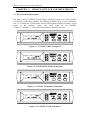
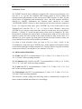
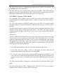
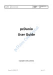
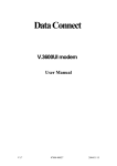
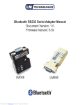
2.6 Connecting With Dial Line
To connect your modem to a permissive RJ11 voice jack and dial line as follows:
1) Connect the 4-pin modular to 4-pin modular cable provided to connect your
modem to telephone set via an RJ11 jack for manual dial operation or voice
transmissions.
2) Connect one end of the 4-pin to 4-pin modular cable to the DIAL connector on
the modem rear panel and the other end to the telephone line modular jack.
The pin layout of the PHONE connector for RJ11 operation is as follows:
Modem PHONE
Connector Pin No.
PHONE
Jack Function
CABLE Wire
Color Assignment
1
2
3
4
5
6
N/C
Not Used
Tip
Ring
Not Used
N/C
N/C
Black
Red
Green
Yellow
N/C
The pin layout of the DIAL LINE connector for RJ11 operation is as follows:
Modem DIAL LINE
Connector Pin No.
DIAL LINE
Jack Function
CABLE Wire
Color Assignment
1
2
3
4
5
6
N/C
Not Used
Tip
Ring
Not Used
N/C
N/C
Black
Red
Green
Yellow
N/C
ON
OFF
DTE
PHONE LEASED DIAL
RJ11
DIAL
RED
LINE
GRN
BOX
TELEPHONE
RJ11 modular telephone cable
RJ11 modular telephone cable
Fig 2-1 : Dial Line Connection
RJ11
INSTALLATION
2-5
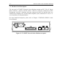
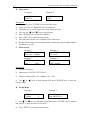
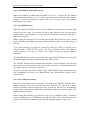
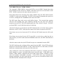
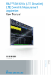
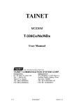
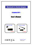
2.7 Connecting With Leased Line
For the leased line connection, you should connect the lines RJ45 connector labeled
with "Leased" on the back of the TAINET Network Series Modem.
Modem
Color
2-Wire
4-Wire
1
Blue
TX/RX
TX
2
Orange
TX/RX
TX
3
Black
4
Red
TX/RX
TX
5
Green
TX/RX
TX
6
Yellow
RX
7
Brown
RX
8
White (or Gray)
RX
Pin No.
Leased
Line
RX
For 2-wire applications, only pin 1, 2 or pin 4, 5 are required. Whereas, You need to
connect pin 1,2,7, 8 or pin 4, 5, 3, 6 in 4-wire applications.
When you connect two modems in "back-to-back" style, don't forget to interchange
TX and RX lines.
ON
OFF
Leased
Line
DTE
TX/2W
TX/2W
RX
RX
BLU
ORG
BWN
WTE
PHONE LEASED DIAL
RJ11
RJ45
RJ45 modular
telephone cable
Back-up Line
( If use dial back-up
feature )
BOX
or
Leased
Line
RX
TX/2W
TX/2W
RX
BLK
RED
GRN
YEW
BOX
Fig 2-2 : Leased Line Connection
2-6
INSTALLATION
This page is intentionally left blank.
CHAPTER 3
FRONT PANEL LCD AND MENU-DRIVEN
CONTENT
3.1 The Front Panel Description
3.2 The Rear Panel Description
3.3 Operating The TAINET Network Series Modem
3.4 The Menu Tree
3.5 Detailed Description of The Menu Tree
FRONT PANEL LCD AND MENU-DRIVEN
3-1
CHAPTER 3 : FRONT PANEL LCD AND MENU-DRIVEN
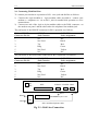
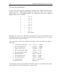
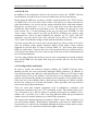
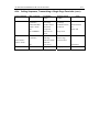
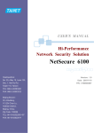
3.1 The Front Panel Description
The front panel of TAINET Network Series Modem contains five touch switches
(VO/DA Key, Right Key, Left Key, ENTER Key and EXIT Key) for direct operation,
one 2 x 16 characters LCD displays and ten LED indicator lights providing a visual
check of the modem's status. The front panel of the TAINET
T-288C, T-1496terbo, T-1496, and ITM-3296bis are illustrated as blew:
V34
288
T-288C
Figure 3-1 TAINET T-288C front panel
144
V32b
ITM-3296bis
L
Figure 3-2 TAINET ITM-3296bis front panel
Terbo
192
T-1496terbo
Figure 3-3 TAINET T-1496terbo front panel
V32b
144T
T-1496
Figure 3-4 TAINET T-1496 front panel
3-2
FRONT PANEL LCD AND MENU-DRIVEN
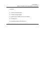
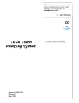
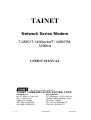
3.2 The Rear Panel Description
The rear panel of TAINET Network Series Modem contains an IEC 320 AC Power
Inlet Connector, a Power On/Off switch, a RS-232 connector (connected to DTE
Equipment), two RJ11 telephone jack (one connected to dail line and the other one
connected to telephone set), and one RJ45 telephone jack (connected to 2-wire or 4wire leased line), as illustrated below.
For more detailed description, please refer to Chapter 2 "INSTALLATION" of this
User's Manual.
115/230 VAC Auto Range
Figure 3-5 TAINET Network Series Modem rear panel
FRONT PANEL LCD AND MENU-DRIVEN
3-3
3.3 Operating The TAINET Network Series Modem
1. Keypads : It consists of 5 touch switches.
VO/DA
It is used as the voice/data select key for dial line application,
Disconnect/Reconnect selection for Leased Line applications, or
"home" key for set-up menu to go back to the home menu.
Left key ; It is used to shift to left field.
Right key; It is used to shift to right field.
ENTER
Enter key; It is used to enter the next lower level menu or confirm
selections.
EXIT
Exit key; use it to go back to the upper level menu.
2. LED Indicator : 10 LED bar
PWR
DTR
DSR
RTS
CTS
TXD
DCD
RXD
OH
TST
-----------
On for power supply ok.
On for DTR signal present.
On for DSR signal present.
On for RTS signal present.
On for CTS signal present.
On for "0", off for "1" TXD signal present.
On for received carrier signal (DCD) present.
On for "0", off for "1", RXD signal present.
On for off-hook.
On for test mode active.
3. LCD Display :
The TAINET Network Series Modem has a 2 by 16 characters LCD with auto
backlight control. Some different pictures of the LCD display are shown below.
A. Top Menu
Example:
V34
288 V42bis
D ANS CONNECT 9
Description:
1) Modem Protocol: V34 288, V32b 144T, V32 96T, V22b 2400, V29 4800 ....
2) Data Protocol: V.42bis, V.42, MNP-5, Normal, Direct.
3) Line Type: D (Dial Line), L (Leased Line).
4) Mode: ANS-Answer Mode, ORG-Originate Mode.
5) Status: Stanby, Handshaking, Connect, Retrain, Ring...
6) SQ: 9,8,7,6....,0
3-4
FRONT PANEL LCD AND MENU-DRIVEN
B. Menu Select
Example 1 :
Example 2 :
L MENU Select
STATUS
L MENU Select
TEST
Description:
1) In top menu, press "ENTER" key to enter this menu.
2) Select "LOCAL"or "REMOTE" first if connected.
3) The character "L" on the upper left corner stands for local.
4)
5)
6)
7)
8)
You may use " " and " " keys to select menu.
Press "ENTER " key to enter the "MENU".
Press "EXIT" key to quit from this menu.
Note that status menu is not available before connection.
Remote Status menu is not available before connecting and secondary channel
should be set to ON.
C. Menu Screen
Example 1 :
L STATUS
RX Level =-10dBm
Example 2 :
R CONFIG MODEM
TX clock
Example 3 :
L TEST
LAL
Example 4 :
L DIAL
Dial a number
(ON)
Description :
1) L-Local, R-Remote.
2) Menu name: STATUS, TEST, DIAL.......
3) Status or setting: RX Level=-10dBm, LAL = ON
4) Use " " or " " keys to shift among field; press "ENTER" key to enter the
selected menu.
D. Set-up Menu
Example 1 :
LL TX Level
-10dBm
Example 2 :
←
R Protocol type
Auto MNP/V42 ←
1) Use " " or " " keys to shift among field, then press "ENTER" key to confirm
and wait for ← appears on the LCD screen.
2) Press "EXIT" key to quit from this menu.
FRONT PANEL LCD AND MENU-DRIVEN
3-5
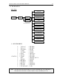
3.4 The Menu Tree
Main Menu
STATUS
DIAL
Version
Top
PROTOCOL
Local
Remote
(If connected)
TEST
CONFIG MODEM
AUXILIARY
CONFIG DTE
COMMAND
LINE SETUP
PROFILE
REMOTE STATUS
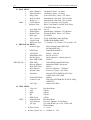
A. STATUS MENU
è
è
è
è
è
è
è
STATUS : è
è
è
è
è
è
è
è
Tx Level
Rx Level
S/N. Ratio
F-Shift
F F-Shift
* Delay
* N Echo
* F Echo
DTE
Retrains
*/ RX Baud
*/ TX Baud
*/ RX Freq
*/ TX Freq
*/ TX PowerOff
= -XX dBm
= -XX dBm
= XX dB
= X.X Hz
= X.X Hz
= XXXX ms
= XX.X dB
= XX.X dB
= XXXXX ASY 10
= XXXXX
= XXXX
= XXXX
= XXXX Hz
= XXXX Hz
= X dB
Note: The function with asterisk mark (*) is only available for V.32 and above.
The function with both (*) and (/) marks is only available for V.34.
3-6
FRONT PANEL LCD AND MENU-DRIVEN
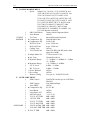
B. DIAL MENU
è
Dial a Number
è
Edit a Number
è
Ring Times
è
Wait For Dial
è
Delay Of " , "
DIAL : è
Call Timeout
è
Progress Tone
è
Auto Dial Tel#
è
Redial Delay
è
Redial Times
è
Dial Type
è
108.1 Action
è
Login Check
è
Short Ans Tone
C. PROTOCOL MENU
è
Protocol Type
è
è
è
è
è
PROTOCOL : è
è
è
è
è
è
MNP Type
V42 Detect
MNP Block Size
Break Option
Send ADP./ODP.
SIM. ENQ.
Discon. Method
DCE-DCE Flow
DCE Inactive
Resend Times
Fast Reset
è
è
XON/XOFF Pass
Connect Code
è
V42 Type
D. TEST MENU
è
Clear All
è
LAL
è
RDL
è
DL
è
RDL Grant
TEST : è
Manu Retrain
è
Test Timeout
è
TP Type
è
è
#0 nnnn\#1 nnnn\...\#9 nnnn
#0 nnnn\#1 nnnn\...\#9 nnnn
Auto ANS Off\1 Times...255 Times
Immediately\1 Seconds...255 Seconds
Immediately\1 Seconds...255 Seconds
Forever\1 Seconds...255 Seconds
Basic Code\Don't Care\Dial Tone \Busy
Tone\Dial+Busy Tone
#0 ..#9
Immediately\1 Minutes...255 Minutes
Disable Redial\1 Times...255 Times
Tone\Pulse
Fixed ANS/ORG \Auto By Ring
Off\By MODEM\By NMS
1.7 seconds / 2.3 seconds / 3.0 seconds / off
Direct\Normal\Auto MNP/V42
\Reliant MNP/V42
None\MNP-4\MNP-5
400 ms...1900 ms
64\128\192\256
Break Option-0\...\Break Option-3
On\Off
None\SIM.Periphral\SIM. Host
Immediate\With Clear-down
Off\On
Forever\1 Minutes...7 Minutes
Forever\12 Times...180 Times
Normal ATZ,AT&F\Fast ATZ \Fast
AT&F \Fast ATZ,AT&F
Off\On
DTE Speed \DTE/MOD /EC\DCE /ARQ
/MOD /EC
None\V42\V42bis
Has Been Done
Off\On
Off\On
Off\On
Off\On
Has Been Done
Forever\1 Minutes...255 Minutes
511\Alter\ 2047 ( is for T-288C and
ITM-3296bis)
Error Count
0 ... 224 -1
♣ Error, Sync Loss 0 ... 999999, 0 ... 255
FRONT PANEL LCD AND MENU-DRIVEN
è
B.E.R. Test
3-7
Off\On
3-8
FRONT PANEL LCD AND MENU-DRIVEN
E. CONFIG MODEM MENU
è
Speed
Adapt\V34+ 336\V34+ 312V34 288\V34 264
\V34 240\V34 216\V34 192\V34 168\V34 144
\V34 120\V34 96\V34 72\V34 48\V34 24
\V32t 192T\V32t 168T\V32b 144T\V32b 120T
\V32 96T\V32 96\V32b 72T\V32 48\V33 144T
\V33 120T\V33 96T\V33 72T\V33 48\V29 9600
\V29 7200\V29 4800\V27 4800\V27 2400
\V26 2400\V26 1200\V23 1200\V23 600
\V22b 2400\V22 1200\BELL 212A\BELL 103
\V21 300 (depend on model)
è
ORG/ANS Mode
Answer Mode\Originate Mode
è
Auto Retrain
On\Off
CONFIG : è
Tx Clock
Internal\External\Loopback
MODEM è
Compromise EQ.
None\M1040\Cable
è ♣ Compromise EQ.
0\4\8\12 dB
è
DCD On Time
0 ms...25500 ms
è
DCD Off Time
0 ms...25500 ms
è
Calling Tone
Off\On
è
V22 Guard Tone
None\550 HZ\1800 HZ (below data
signal level 6dB)
è
Adapt Mode Sel
V.32bis Annex\V.100
è ♣ AA Tone
Normal\Forced On
è
Dynamic Range
+3..-26dBm\+3..-40dBm\-6..-33dBm
\-6..-43dBm
è ♣ Dynamic Range
\+4..-33dBm\-4..-43dBm
è
LL Tx Level
0 dBm...-31 dBm
è
DL Tx Level
0 dBm...-15 dBm
è */ Power Backoff
Off\On
è */ Pre-coding
Off\On
è
Remote Config
\S-reg n= 0~ 59\SAVE\LOAD
F. AUXILIARY MENU
è
SPK.Control
Until DCD On\Always On \Off When
Dial\Off
è
SPK.Volume
Low\Medium\High
è
Auto FB/FF
Off/On
è ♣ Compromise EQ.
0\1\2\3 dB
è
Send Break
Off\On
è
Long Space Off
Off\On
è
ASI Overspeed
+1%\+2.3%
è
V32/33 96T THR
0dB...49dB
è
120T/96 THR
0dB...49dB
è
V32/33 72T THR
0dB...49dB
è
V32/33 48Q THR
0dB...49dB
AUXILIARY : è
V29/22 96/24Q THR 0dB...49dB
è
V34 144T SNR THR 0dB...49dB
è
V29 72 THR
0dB...49dB
FRONT PANEL LCD AND MENU-DRIVEN
3-9
è ♣ DL Check Time
Forever\1..255 Minutes
è */ TCM State
16\32\64
è
Echo Protect
Off\On
è
RDL By 140
Off\On
è
AL By 141
Off\On
è */ V34 Baud Rate
2400\2743\3000\3200\3429
è
Make/Break
US (39%)\UK (33.3%)
è
Ring Off Time
0 Seconds...15 Seconds
è
Call-Back
Off\On
è
Call-Back Time
Immediately\1 Seconds...255 Seconds
è
Call-Back TEL#
#0...#9
è
DTMF Duration
0 ms...255 ms
è
Backlight
On\Off\Auto
è
Remote Grant
On\Off
è
SPK. Monitor
Rx\Rx+Tx
è
Ctrl Carrier
On\Off
è
Jitter Filter
On\Off
è
Auto FB/FF
On\Off
è
Secondary CH.
On\Off
è */ Constellation
Normal\Expansion
è */ TX Warping
On\Off
Note: The function with ( ) mark is only available for T-288C & ITM-3296bis.
The function with (♣) mark is only available for T-1496 & T-1496terbo.
The function with (¡¯/)mark is only available for T-288C.
G. CONFIG DTE MENU
è
è
è
è
è
è
CONFIG : è
DTE è
è
è
è
è
è
è
è
DTE Speed
115200 bps\76800 bps\57600 bps\38400bps
\33600bps*\31200bps*\28800 bps*\26400 bps*
\24000 bps*\21600 bps*\19200 bps\16800 bps*
\14400 bps\12000 bps\9600 bps\7200bps \4800
bps\3600 bps\2400 bps\1800 bps \1200 bps
\600 bps\300 bps (* is for V.34 only.)
Flow Control
Off\X-On, X-Off\RTS/CTS\CTS only
DTR Control
Normal\Auto Dial/ANS
DTR Off Action
Force On\Command Mode
\Disconnect\Modem Reset
DSR Control
Force On\ Normal
DCD Control
Normal\V.13 HDX\Psuedo HDX \Force
On
RTS Control
Force On\Normal
RTS/CTS Delay
0 ms...2550 ms
DTR Drop Time
0 ms...1500 ms
Data Format
SYNC\ASYNC
CTS Control
follow CCITT\follow EIA
DTR Rise Time
0 ms...1500 ms
OH By DTR
Off\On
Total Bits
8\9\10\11
Parity
None\Even\Odd
3-10
FRONT PANEL LCD AND MENU-DRIVEN
è
Stop Bit
1\1.5\2
FRONT PANEL LCD AND MENU-DRIVEN
3-11
H. COMMAND MENU
è
Command Mode
è
è
è
è
è
COMMAND : è
è
è
è
è
Result Form
Result Code
Command Echo
AT Prefix
Escape Code
EOL Code
LF Code
Backspace Code
Escape Guard
Framing
AT Command\V.25bis Command \I-Tek
Mode\Dumb Mode
Short\Long
Off\On
Off\On
On\Off
0...255
0...255
0...255
0...255
0 ms...25500 ms
ASYNC\HDLC/SDLC
\BI-SYNC\MONO-SYNC
If you select ASYNC, then the following menu tree will be shown as below:
è
è
è
Data Bit LEN.
Parity
Stop Bit
5\6\7\8
None\Even\Odd
1\1.5\2
If you select HDLC/SDLC, then the following menu tree will be shown as below:
è
è
è
Check Sum
Addr Define
Setup Addr
None\CRC-CCITT
Global\User Define
0...255 (Available for "User Define".)
If you select BI-SYNC, then the following menu tree will be shown as below:
è
è
Check Sum
Code Format
è
è
è
SYNC Define
SYNC Char1
SYNC Char2
None\CRC-16
ASCII 8-N-1\EBCDIC 8-N-1
\ASCII 7-0-1
Default Value\User Define
0...255 (Available for "User Define".)
0...255 (Available for "User Define".)
If you select MONO-SYNC, then the following menu tree will be shown as below:
è
è
Check Sum
Code Format
è
è
è
SYNC Define
SYNC Char1
SYNC Char2
None\CRC-16
ASCII 8-N-1\EBCDIC 8-N-1
\ASCII 7-0-1
Default Value\User Define
0...255 (Available for "User Define".)
0...255 (Available for "User Define".)
3-12
FRONT PANEL LCD AND MENU-DRIVEN
I. LINE SETUP MENU
Line Type
Leased To Dial
L → D Timer
Retrain Times
Backup Tel#1
Backup Tel#2
Backup Speed
è
è
è
è
è
LINE : è
SETUP è
è
è
è
è
è
è
è
è
Dial Line\2W Leased\4W Leased
Manu\Auto
Forever\1 Minutes...255 Minutes
Disconnect only\1 Times...255 Times
#0...#9
None\#0...#9
Adapt\V34E 336\V34E 312\V34 288
\V34 264\V34 240\V34 216\V34 192
\V34 168\V34 144\V34 120\V34 96
\V34 72\V34 48\V34 24 \V32t 192T
\V32t 168T \V32b 144T\V32b 120T
\V32 96T\V32 96\V32b 72T\V32 48
\V33 144T\V33 120T\V33 96T\V33 72T
\V33 48\V29 9600\V29 7200\V29 4800
\V27 4800\V27 2400\V26 2400\V26 1200
\V23 1200\V23 600\V22b 2400\V22 1200
\BELL 212A\BELL 103\V21 300
(depend on model)
Dial To Dial
Off\On
D → L Timer
Forever\1 Minutes...255 Minutes
Dial To Leased
Manu\Auto
Broken Discon
Off\On
4w Echo Cancel
Off\On
♣
Echo Canceller Short/Long
RTrip-HandShake
Off\On
V32b Fast-Train
Off\On
Note: The function with ( ) mark is only available for T-288C & ITM-3296bis.
The function with (♣) mark is only available for T-1496 & T-1496terbo.
J. PROFILE MENU
PROFILE :
è
Load
è
Load
è
è
User Profiles #0...#9(#0...#1 Rack) (for T-288C & ITM-3296bis)
\0:AS-DL-AT-NONE
\1:AS-DL-AT-AUTO
\2:SY-DL-V25-NONE
\3:AS-2L-ANS-V34/32b
\4:AS-2L-ORG-V34/32b \5:SY-2L-ANS-V34/32b
\6:SY-2L-ORG-V34/32b \7:SY-4L-ANS-V34/32b
\8:SY-4L-ORG-V34/32b \9:SY-4L-V33/V29
User Profiles #0...#9(#0...#1 Rack) (for T-1496 & T-1496terbo)
\0:AS-DL-AT-NONE
\1:AS-DL-AT-AUTO
\2:SY-DL-V25-NONE
\3:AS-2L-ANS-32b/32t
\4:AS-2L-ORG-32b/32t \5:SY-2L-ANS-32b/32t
\6:SY-2L-ORG-32b/32t \7:SY-4L-ANS-32b/32t
\8:SY-4L-ORG-32b/32t \9:ASY-2L-ANS-REL
Save
User Profiles#0...#9
Password Edit
Enter:
FRONT PANEL LCD AND MENU-DRIVEN
è
Front Lock
3-13
Unlock\Lock
3-14
FRONT PANEL LCD AND MENU-DRIVEN
K. REMOTE STATUS MENU
REMOTE
STATUS :
è
è
è
è
è
è
è
è
è
è
è
è
è
è
è
è
Tx Level
= -XX dBm
Rx Level
= -XX dBm
S/N. Ratio
= XX dB
F-Shift
= X.X Hz
F F-Shift
= X.X Hz
* Delay
= XXXX ms
* N Echo
= XX.X dB
* F Echo
= XX.X dB
DTE
= XXXXX ASY 10
Retrains
= XXXXX
*/ RX Baud
= XXXX
*/ TX Baud
= XXXX
*/ RX Freq
= XXXX Hz
*/ TX Freq
= XXXX Hz
*/ TX PowerOff = X dB
TR(tr) MR(mr) RS(rs) CS(cs) CD(cd) T(t)
Note1: The function with asterisk mark (*) is only available for V.32 and above.
The function with both (*) and (/) marks is only available for V.34.
Note2: The Secondary Channel shall be active (On) to enable the remote status
function.
FRONT PANEL LCD AND MENU-DRIVEN
3-15
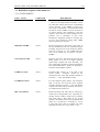
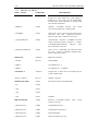
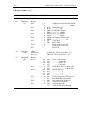
3.5 Detailed Description of the menu tree
3.5.1 STATUS MENU
ITEM
NAME
COMMAND
DESCRIPTION
TX LEVEL= -XX dBm
AT%S
Transmitted signal level. This value is equal to the
" TX level" of config modem. Normally, for the
2w leased line and the dial line, the recommended
value is between -7 and -10dBm. A higher level
may create an interference. 4w leased line should
be between 0 and -31dBm. It can be increased of
in order to obtain a more satisfactory S/N ratio
(siganl to noise ratio) by setting a higher level as
possible, but a saturation of the active
transmission equipment should be avoided. The
Tx level level should be setting under -8dBm
while to operating V.34 mode.
RX LEVEL= -XX dBm
AT%S
Received signal level. This value is the result of
the line attenuation from the transmitted signal.
Normally, the RX level of 2w leased line and the
dial line is between -15 and -33dBm while the
level of 4w leased line is between -10 and 26dBm.
S/N. RATIO=XX dB
AT%S
Signal to noise ratio. The bigger the S/N ratio, the
better quality of a line is. A higher operating
speed needs a higher S/N ratio. Normally, the
S/N requirement of running 14400 bps should be
more than 24 dB while to operate at 9600 bps, a
S/N better than 20 dB is required.
F-SHIFT=X.X Hz
AT%S
Frequency-shift (offset). It is the shift of the
carrier central
frequency caused by the
transmission link. This shift normally should be
less than + / - 7 Hz. The smaller is better.
F F-SHIFT=X.X Hz
AT%S
Far end frequency-shift (offset). The frequency
shift of the far end received carrier signal.It
normally should be less than +/- 7 Hz. The smaller
is better. The value will not accurate once level is
too small from the remote site.
DELAY=XXXX ms
AT%S
Round trip delay time. This delay is caused by a
round trip of a long distance line , especially in a
satellite circuit. Usually, round trip of a satellite
link shall create a time delay of 0.5 second
(500ms). The modem will accept a maximum time
delay of 1.5 seconds for V.34 mode, 2.1 sec for
V.32/V.32bis (This value is provided only when
operating on 2-wire of V.32 /V.32bis / V.34).
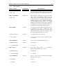
3-16
FRONT PANEL LCD AND MENU-DRIVEN
N ECHO=-XX.X dB
AT%S
Near end echo. This echo is caused when the near
end line impedance is not matched. A smallest
near end echo is always required. The normal near
end echo level is between -6 dB and -20 dB (This
value is provided only when operating on 2-wire
of V32/V.32bis/V.34).
F ECHO=-XX.X dB
AT%S
Far end echo. This echo is caused when the far
end line impedance is not matched. A smallest far
end echo level is always required. Normally,the
far end echo level is between -20 dB and -55 dB
(This value is provided only when operating on 2wire of V.32 / V.32bis / V.34).
DTE=XXXXX ASY 10
AT%S
Indication of speed and data format of DTE.
examples: DTE = 19200 ASY 10 stands
19200 bps Asynchronous 10 bits in total
length. DTE=14400 SYN means 14400
synchronous.
RETRAINS=XXXX
For
for
bit
bps
Total retrain count. From the total retrain count,
you will find the total times of line interference
occurred. This value will not be cleared
automatically unless pressing the "ENTER" key
or power off.
RX BAUD=XXXX
AT%S
Indication of the signalling rate of received signal.
For examples: RX Baud=3429 means the
switching speed or number of transitions is 3429,
however, one baud can be made to represent more
than one bit per second. (This value is only
available when operating on V.34).
TX BAUD=XXXX
AT%S
Indication of the signalling rate of transmitted
signal. (This value is only available when
operating on V.34).
RX FREQ=XXXXHz
AT%S
Indication of the carrier frequency of received
signal. For examples: RX Freq = 1959Hz means
the unique frequency used to to "carry" data is
1959 Hz. (This value is only available when
operating on V.34).
TX FREQ=XXXXHz
AT%S
Indication of the carrier frequency of transmitted
signal. (This value is only available when
operating on V.34).
TX POWEROFF=XdB
AT%S
Indication of a reduction of transmit power level.
For examples: TX PowerOff = 6dB means the
transmit power level is requested to reduce 6 dB
by the remote modem. (This value is only
available when operating on V.34).
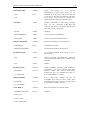
FRONT PANEL LCD AND MENU-DRIVEN
3-17
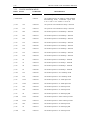
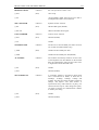
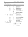
3.5.2 DIAL MENU
ITEM
NAME
DIAL A NUMBER
COMMAND
DESCRIPTION
ATDSn
Dial out a preset telephone number #n(n=0..9).
This function can interact with the auto redial
function or dial line auto establishment function.
AT&Zn=xx
Edit telephone number #n (n=0..9) for 20 digits
each group. If a telephone number is set the
symbol of "@" and auto redial is ON, when place
a call and can not get through,another group of
telephone number will be dialed automatically
until the telephone number without "@" is dialed
and then it will return to the first group. Therefore
a maximum of 10 groups of telephone number can
be obtained for an intelligent redial function.
RING TIMES
ATS0=n
Auto answer activates when detected ring count =
n (default=2). *If 108.1
(DTR ON Auto
Dial/Ans) is used for auto answer, it must be set to
OFF and the answer shall be activated by DTR
provided by DTE (default value=2 times).
ç AUTO ANS OFF
ATS0=0
/Turn off the auto answer function.
ç /#0.......#9
EDIT A NUMBER
ç /#0.......#9
ç 1..255 TIMES
/An auto answer will be given when bell rings
1..255 times.
WAIT FOR DIAL
ATS6=n
Time to wait for dial (default value=2 sec.).
ç IMMEDIATELY
ATS6=0
/Immdeiately .
ç 1..255 SECONDS
DELAY OF ","
/1....255 sec.
ATS8=n
Time delay when symbol "," is encountered
during dialing (default value = 2 sec.).
ç IMMEDIATELY
/Immediately.
ç 1..255 SECONDS
/1....255 sec.
CALL TIMEOUT
ATS7=n
Time to wait for line connection after dialing
(default value = 45 sec.).
ç FOREVER
/Forever.
ç 1..255 SEC.
/1....255 sec.
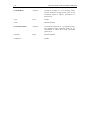
3-18
FRONT PANEL LCD AND MENU-DRIVEN
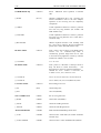
PROGRESS TONE
ATXn
Select if detect of busy tone or dial tone to
proceed dialing.
ç BASIC CODE
ATX0
/Don't care any tone and do not
connection speed.
ç DON'T CARE
ATX1
/Don't care busy tone and show line connection
speed.
ç DIAL TONE
ATX2
/Don't care busy tone and show line connection
speed.
ç BUSY TONE
ATX3
/Don't care dial tone and show line connection
speed.
ç DIAL + BUSY TONE
ATX4
/Do care dial tone, busy tone and extended result
code (default).
AUTO DIAL TEL#
ATS51=n
Select telephone number in DTR-ON auto dial
mode (CCITT 108.1).
ç #0...#9
(bit 3....0)
REDIAL DELAY
ATS44=n
Pause time between auto redial.
ç IMMEDIATELY
ATS44=0
*This setting is limited to more than 3 minutues in
Taiwan and some other countries.
ç 1...255 MINUTES
show line
/default=1 minute.
REDIAL TIMES
ATS38=n
Set times of redial.
ç DISABLE REDIAL
ATS38=0
/Disable auto redial function.
ç 1..255 TIMES
/255 times means to proceed redial until line is
successfully connected.
DIAL TYPE
Select dial type.
ç PULSE
ATP
/Pulse dial (default).
ç TONE
ATT
/Tone (DTMF) dial.
108.1 ACTION
Select 108.1 action type.
ç FIXED ANS/ORG
/Fixed ANS/ORG (default).
ç AUTO BY RING
/Auto By Ring
LOGIN CHECK
Select call in security check function for dial-line
application.
ç OFF
/Login check disable (default).
ç BY MODEM
/Login check by the presented telephone number
stored on the modem device (#0 ~ #9).
ç BY NMS
/Login check by the Tainet Manager System.
SHORT ANS TONE
FRONT PANEL LCD AND MENU-DRIVEN
ç 1.7 seconds / 2.3
seconds / 3.0 seconds
ç off
3-19
/selections for quick connection to POS system
3-20
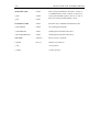
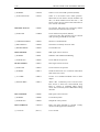
FRONT PANEL LCD AND MENU-DRIVEN
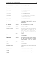
3.5.3 PROTOCOL MENU
ITEM
NAME
COMMAND
DESCRIPTION
PROTOCOL TYPE
AT\Nn
Select error correction and data com-pression
function for async mode only. *This setting is
ineffective in sync mode. It will automatically
become direct mode regardless of setting made
once the link established.
ç DIRECT
AT\N0
/Without V.42/MNP function and
conversion (DTE speed = modem speed).
ç NORMAL
AT\N1
/With DTE speed conversion but without error
correction and data compression function.
However, data flow control has to be active.
ç AUTO MNP/V42
AT\N2
/Automatically negotiate V.42/MNP level with
remote mode.The priority sequence is V.42bisV.42-MNP5-MNP4-Normal.
However , data
flow control has to be used.
ç RELIANT MNP/V42
AT\N3
/Link can be established only when both sides
use V.42 / V.42bis or MNP4/5 simultaneously,
must use data flow control.
MNP TYPE
ATS39=n
MNP level selection.
ç NONE
(bit3..0)
/Disable MNP.
ç MNP-4
/Use MNP level 1..4.
ç MNP-5
/Use MNP level 1..5 (default).
speed
V42 DETECT
ATS42=n
Longest time to detect the V.42/V.42bis protocol
in auto reliable mode.
/400 ms...1900 ms
(bit7..4)
/default = 1900 ms.
MNP BLOCK SIZE
AT\An
The largest block size in MNP mode.
ç 64
AT\A0
ç 128
AT\A1
ç 192
AT\A2
ç 256
AT\A3
/(default).
BREAK OPTION
AT\Kn
Selection of handling method
sequence received.
ç Break Option-0
AT\K0
/Expedited destructive.
ç Break Option-1
AT\K1
/Expedited non-destructive.
ç Break Option-2
AT\K2
/Queued (default).
ç Break Option-3
AT\K3
/Reserved. Don't use it now.
when
break
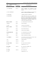
FRONT PANEL LCD AND MENU-DRIVEN
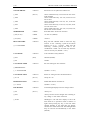
SEND ADP./ODP.
ATS40=n
ç OFF
(bit3)
ç ON
3-21
During the process of V.42 protocol
identification,a special fixed signal will be
identified if V.42 protocol can be provided. But
if the user be sure that the modem of both sides
use or not use V.42, he may set to OFF so as to
speed up the line connection. (default is ON).
SIM. ENQ.
AT\Hn
Emulate ENQ/ACK in DTE pacing, normally
used for the connection of HP Host and
terminals. This function can be used together with
DTE flow control or used alone.
ç NONE
AT\H0
/(default).
ç SIM. PERIPHRAL
AT\H1
/Use in connection with HP Host.
ç SIM. HOST
AT\H2
/Used in connection with HP terminal.
DISCON. METHOD
ATS40=n
Disconnect method for V.32/V.32bis/V.34.
ç IMMEDIATE
(bit2)
/Immediate disconnect.
ç WITH CLEAR-DOWN
/Send clear down before disconnection.
DCD-DCE FLOW
AT\Gn
To activate DCE-DCE flow control or not in
normal mode.
ç OFF
AT\G0
/Disable. Normally, DCE-DCE flow control is
not necessary unless DTE speed < modem speed
(default).
ç ON
AT\G1
/Enable.
DCE INACTIVE
ATS43=n
ç FOREVER
(bit2...0)
Under V.42/MNP operation, if the dataflow is
interrupted by any reason caused by DCE with
duration longer than this set time period,
modem will give up V.42/MNP and return to
direct mode.(default = 1 minute).
ç 1..7 MINUTES
RESEND TIMES
ATS42=n
ç FOREVER
(bit3...0)
For a single block, modem will give up
V.42/MNP and retrun to direct mode when
resending times is more than this setting caused
by any reasons. (default = forever).
ç 12..180 TIMES
FAST RESET
ATS32=n
Reset rate selection for ATZ and AT&F
ç NORMAL ATZ,AT&F
(bit0,1)
/(default)
ç FAST ATZ
ç FAST AT&F
ç FAST ATZ,AT&F
3-22
FRONT PANEL LCD AND MENU-DRIVEN
When using XON/XOFF as data flow control in
V.42/MNP/Normal mode, modem can choose to
intercept XON/XOFF signal or have it be sent as
data to the remote modem (default = OFF).
XON/XOFF PASS
AT\Xn
ç OFF
AT\X0
ç ON
AT\X1
CONNECT CODE
ATWn
Send back the V.42/MNP extended result code.
ç DTE SPEED
ATW0
/No sending back (default).
ç DTE/MOD/EC
ATW1
/Sending back extended result code 1.
ç DCE/ARQ/MOD/EC
ATW2
/Sending back extended result code 2.
V42 TYPE
ATS39=n
Select CCITT V.42 Mode.
ç NONE
(bit5..4)
/Disable V.42 function.
ç V42
/V.42 protocol.
ç V42bis
/V.42bis protocol.
FRONT PANEL LCD AND MENU-DRIVEN
3-23
3.5.4 TEST MENU
ITEM
NAME
COMMAND
DESCRIPTION
CLEAR ALL
AT&T0
Clear all the tests in one time, and a statement
"Has been done" shall be shown.
LAL
AT&T1
Local analog loop test (ON/OFF).This test is
normally used to certify if the modem is in
normal operation condition. Also, this test is
usually carried out together with B.E.R test.
AT&T6
For remote digital loop test (ON/OFF). This
test can control remote modem to executive
digital loop for BER test to find out if the
modem and line of both ends are in normal
condition.
AT&T3
For digital loop test (ON/OFF). This test enable
the received digital data demodulated and send
back to match with the far end test.
AT&T4
Set for accepting remote digital loop(RDL) test.
ç ON
ç OFF
RDL
ç ON
ç OFF
DL
ç ON
ç OFF
RDL GRANT
ç ON
/Enable. (default).
ç OFF
/Disable.
MANU RETRAIN
ATO1
Forcing modem for retrain.
TEST TIMEOUT
ATS18=n
Set for test time duration.
ç FOREVER
ATS18=0
/Continuous.
ç 1..255 MINUTES
/1...255 MIN.
TP TYPE
AT%Tn
Test patterns selection (CCITT V.52 Rec.)
ç ALTER
AT%T0
/1010... alternative pattern (default).
ç 511
AT%T1
/"511" pattern.
ç 2047
AT%T2
/"2047" pattern (T-288C & ITM-3296bis only).
ERROR COUNT
Bit error count display function.
ç 0....224 -1
Press Left or Right shift key to insert error. Press
"ENTER" key to clear.
B.E.R. TEST
AT&T10
Set bit error rate test function.
ç ON
/Enable.
ç OFF
/Disable (default).
3-24
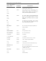
FRONT PANEL LCD AND MENU-DRIVEN
3.5.5 CONFIG MODEM MENU
ITEM
NAME
COMMAND
DESCRIPTION
SPEED
AT%Gn
Set modem speed
ç ADAPTIVE
AT%G0
/Set modem speed to be adaptive (multi-standard
hand-shaking) mode, connectable speed from
V.34 / V.32b / V.32 / V.22bis / V.22 /V.21.
ç V34+
336
AT%G42
/Set speed to V34 Extended 33.6k bps...4DTCM
ç V34+
312
AT%G41
/Set speed to V34 Extended 31.2k bps...4DTCM
ç V34
288
AT%G28
/Set modem speed to V34 28800bps....4DTCM
ç V34
264
AT%G37
/Set modem speed to V34 26400bps....4DTCM
ç V34
240
AT%G27
/Set modem speed to V34 24000bps....4DTCM
ç V34
216
AT%G36
/Set modem speed to V34 21600bps....4DTCM
ç V34
192
AT%G26
/Set modem speed to V34 19200bps....4DTCM
ç V34
168
AT%G35
/Set modem speed to V34 16800bps....4DTCM
ç V34
144
AT%G34
/Set modem speed to V34 14400bps....4DTCM
ç V34
120
AT%G38
/Set modem speed to V34 12000bps....4DTCM
ç V34
96
AT%G33
/Set modem speed to V34 9600bps....4DTCM
ç V34
72
AT%G32
/Set modem speed to V34 7200bps....4DTCM
ç V34
48
AT%G31
/Set modem speed to V34 4800bps....4DTCM
ç V34
24
AT%G40
/Set modem speed to V34 2400bps....4DTCM
ç V32t
192
AT%G30
/Set modem speed to V.32t 19200 bps TCM.
ç V32t
168
AT%G29
/Set modem speed to V.32t 16800 bps TCM.
ç V33
144T
AT%G25
/Set modem speed to V.33 14400 bps TCM.
ç V33
120T
AT%G24
/Set modem speed to V.33 12000 bps TCM.
ç V33
96T
AT%G23
/Set modem speed to V.33 9600 bps TCM.
ç V33
72T
AT%G22
/Set modem speed to V.33 7200 bps TCM.
ç V33
48
AT%G21
/Set modem speed to V.33 4800 bps QAM.
ç V32b
144T
AT%G20
/Set modem speed to V.32bis 14400 bps TCM.
ç V32b
120T
AT%G19
/Set modem speed to V.32bis 12000 bps TCM.
ç V32
96T
AT%G18
/Set modem speed to V.32 9600 bps TCM.
ç V32
96
AT%G17
/Set modem speed to V.32 9600 bps QAM.
ç V32b
72T
AT%G16
/Set modem speed to V.32 7200 bps TCM.
FRONT PANEL LCD AND MENU-DRIVEN
3-25
ç V32
48
AT%G15
/Set modem speed to V.32 4800 bps QAM.
ç V29
9600
AT%G14
/Set modem speed to V.29 9600 bps QAM.
ç V29
7200
AT%G13
/Set modem speed to V.29 7200 bps DPSK.
ç V29
4800
AT%G12
/Set modem speed to V.29 4800 bps DPSK.
ç V27
4800
AT%G11
/Set modem speed to V.27bis 4800 bps DPSK.
ç V27
2400
AT%G10
/Set modem speed to V.27bis 2400 bps DPSK.
ç V26
2400
AT%G9
/Set modem speed to V.26 2400 bps DPSK.
ç V26
1200
AT%G8
/Set modem speed to V.26 1200 bps DPSK.
ç V23
1200
AT%G7
/Set modem speed to V.23 1200 bps FSK.
ç V23
600
AT%G6
/Set modem speed to V.23 600 bps FSK.
ç V22b
2400
AT%G5
/Set modem speed to V.22bis 2400 bps QAM.
ç V22
1200
AT%G3
/Set modem speed to V.22 1200 bps DPSK.
ç V21
300
AT%G1
/Set modem speed to V.21 300 bps FSK.
ç BELL
212A
AT%G4
/Set modem speed to BELL 212A 1200 bps
DPSK.
ç BELL
103
AT%G2
/Set modem speed to BELL 103 300 bps FSK.
ORG/ANS MODE
ATS14=n
Set modem as the originate or answer mode.
ç ORIGINATE MODE
(bit7)
/For V.34/ V.32/ V.32bis/ V.22bis/ V.22/ V.21/
V.23 / BELL-212A / BELL103 in 2/4-wire FDX
operation. It must be set in different mode on
each side.
AUTO RETRAIN
AT%En
The automatic adaptive equalizer can be readjusted via retrain procedure activated
automatically when the S/N become worse than
the preset threshold.
ç ON (FAST)
AT%E0
/High sensitivity, retrain occurs according to S/N
ratio.
ç OFF (SLOW)
AT%E1
/Low sensitivity, retrain occurs according to S/N
ratio.
TX CLOCK
AT&Xn
Select transmit clock source.
ç INTERNAL
AT&X0
/Internal clock source, for most point to point
application.
ç EXTERNAL
AT&X1
/External
clock
source, for cascade and
TDM/STDM network application.
ç LOOPBACK
AT&X2
/Received clock source, for used in slave side of
polling nerworks or the modem in the most far
end of a cascading network.
ç ANSWER MODE
3-26
FRONT PANEL LCD AND MENU-DRIVEN
COMPROMISE EQ.
ATS24=n
Select
side.
additional fixed equalizer at transmit
ç NONE
(bit3..2)
/Disable, compromise EQ is not necessary for
normal transmission line as the auto adaptive
equalizer at the receiving end can completely
compensate.
ç CABLE
/Cable equalization function. Used for a practical
line with very long distance (for T-288C and
ITM-3296bis only).
ç 0\4\8\12dB
/Cable equalization function. Used for a practical
line with very long distance (for T-1496 and T1496terbo only)
ç M1040 LINE
/M1040 equalizer function. This normally used
for a poor line to improve the line transmission
quality (for T-288C and ITM-3296bis only).
DCD ON TIME
ATS9=n
ç 0..25500ms
DCD OFF TIME
Time period used to detect a real DCD sugnal.
Carrier can be confirmed only when it
continuously presents longer than the set time
to avoid incorrect judgement caused by transient
interference (default = 0.6 seconds).
/0.1...25.5 sec.
ATS10=n
Time period to determine a interrupt carrier to
drop off DCD to aboid unnecessary
line
disconnection caused by transient interference.
/Default for V.34 / V.32bis / V.32=15sec, for
V.22bis=1.5 sec, for V.29/V.33=5 sec.
ç 0..25500 ms
/For V.34,V.33,V.32b,V.32,V.29,V.27bis,V.26
ç 0..25500 ms
/For V.22bis,V.22,V.21,V.23,BELL103,212A.
CALLING TONE
ATS14=n
Send calling tone or not.
ç ON
(bit0)
/Send calling tone.
ç OFF
/Not send (default).
V22 GUARD TONE
AT&Gn
Set for V.22 guard tone.
ç NONE
AT&G0
/Guard tone off (default).
ç 550 Hz
AT&G1
/Send out 550 Hz guard tone.
ç 1800 Hz
AT&G2
/Send out 1800 Hz guard tone.
ADAPT MODE SEL
AT%Mn
Multi-standard handshaking mode select.
ç V.100
AT%M0
/Select CCITT V100 mode (for T-288C and ITM3296bis only).
ç V.32bis ANNEX
AT%M1
/Select CCITT V.32bis ANNEX mode (default).
FRONT PANEL LCD AND MENU-DRIVEN
3-27
DYNAMIC RANGE
ATS40=n
Set receive dynamic range.
ç +4..-33dBm
(bit7..6)
/for T-1496 & T-1496terbo.
ç -4..-43dBm
/for T-1496 & T-1496terbo (default).
ç +3..-26 dBm
/for T-288C & ITM-3296bis
(V.33/V.29 default).
ç -6..-33 dBm
/for T-288C & ITM-3296bis.
ç -6..-43 dBm
/for T-288C & ITM-3296bis (V.34/V.32bis/V.32
/V.22bis/V.22/V.21/V.23 default)
ç +3..-40 dBm
/for T-288C & ITM-3296bis.
LL TX LEVEL
AT%Ln
Set leased line transmit level.(TXL)
/default TXL= -8 dBm for 4w L-L. TXL= -10
dBm for 2w L-L.
ç 0..-31 dBm
DL TX LEVEL
ATS30=n
Set dial line transmit Level, 0..-15 dBm.
ç 0..-15 dBm
(bit7..5)
/(default = -10 dBm).
POWER BACKOFF
ATS43=n
In V.34 operating mode, the remote modem may
request reduction in the transmit power level
(power backoff) when a significant amount of
non-liner distortion is detected during line
probing.
ç ON
(bit3)
/Enable
/Disable (default).
ç OFF
PRE-CODING
ATS45=n
In V.34 operating mode, precoding will remove
the effect of noise enhancement in the modem
receive equalizers on lines with attenuation
distortion.
ç ON
(bit0)
/Enable
ç OFF
/Disable (default).
REMOTE CONFIG
Only available when connected and Secondary
CH. is on.
ç S-REG N=XX
/read or set remote modem's S-register.
ç LOAD
/Command remote modem to load profile.
ç SAVE
/Command remote modem to save profile.
3-28
FRONT PANEL LCD AND MENU-DRIVEN
3.5.6 AUXILIARY MENU
ITEM
NAME
COMMAND
DESCRIPTION
SPK. CONTROL
ATMn
Monitoring speaker switch control.
ç UNTIL DCD ON
ATM1
/Speaker turn on until DCD ON,then turn off
(default).
ç ALWAYS ON
ATM2
/Keep speaker always on.
ç OFF WHEN DIAL
ATM3
/Turn on speaker after dialing is completed, and
then detect until to find out carrier and then turn
off speaker.
ç OFF
ATM0
/Keep speaker always off.
SPK. VOLUME
ATLn
Speaker vloume control.
ç LOW
ATL0,1
/Set speaker volume to low (default).
ç MEDIUM
ATL2
/Set to medium.
ç HIGH
ATL3
/Set to high.
AUTO FB/FF
ATS24=n
(Bit5..4)
The modem continuously monitors the S/N ratio
of the telephone line, then fallback or fall forward
data rate automatically when the S/N ratio lower
or higher.
ç ON
(bit0)
/Enable
ç OFF
SIGNAL MONITOR
/Disable (default).
ATS24=n
(bit5..4)
ç 0\1\2\3 dB
Reserved. (Auto FB/FF ¦Û°Êª@°³t)
/Cable equalization function. (Fine Tune)
SEND BREAK
AT\Bn
Send break sequence before line disconnection.
ç OFF
AT\B0
/No sending (default).
ç ON
AT\B1
/Sending.
LONG SPACE OFF
ATYn
Select auto disconnection option when long space
signal received.
ç ON
ATY1
/Enable.
ç OFF
ASI OVERSPEED
ATY0
AT%An
/Disable (default).
Select async data speed tolerance.(ITU-T V.14)
ç +1%
AT%A0
/Basic range +1% to -2.5% (default).
ç +2.3%
AT%A1
/Extended overspeed range +2.3% to -2.5%.
V32/V33 96T THR
ATS46=n
Set V.32bis/V.33 9600 TCM auto retrain
threshold. Decreasing this value if the line is
seriously interfered. If the setting is below 10 dB,
it means this speed is not used.
/(default = 16 dB).
ç 0...49dB
FRONT PANEL LCD AND MENU-DRIVEN
120T/96 THR
ATS47=n
ç 0...49 dB
V32/V33 72T THR
ATS59=n
ATS48=n
Set V.32bis/V.33 7200 TCM retrain threshold.
Set V.32/V.33 4800 QAM retrain threshold.
/(default = 13 dB).
ATS49=n
ç 0...49 dB
V34 144T SNR THR
V.32 9600
/(default = 15 dB).
ç 0...49 dB
V29/V22 96/24Q SNR TH
Set V.32bis/V.33 12000 TCM &
QAM mode retrain threshold.
/(default = 18 dB).
ç 0...49 dB
V32/V33 48Q SNR THR
3-29
Set V.29 9600
threshold.
&
V.22bis
2400
retrain
/(default = 16 dB).
ATS56=n
Set V.32bis/V.33 14400 TCM and V.34 4DTCM
retrain threshold.
/(default = 25 dB).
ATS57=n
Set V.29 7200 DPSK retrain threshold.
(for T-288C & ITM-3296bis only)
/(default = 15 dB).
ATS58=n
(bit4..3)
Set trellies code state. (for T-288C V.34 only)
ç 0...49 dB
V29 72 THR
ç 0...49dB
TCM STATE
ç 16
/16 trellies code (default).
ç 32
/32 trellies code.
ç 64
/64 trellies code.
DL CHECK TIME
ATS58=n
ç FOREVER
ATS58=0
ç 1..255 MINUTES
Set for Dial Tone Detect time duration.
(for T-1496 & T-1496terbo only).
/Continuous.
/1...255 MIN.
ECHO PROTECT
ATS29=n
ç OFF
(bit6)
ç ON
V.26/V.27ter 2-wire half-duplex mode
echo protection.
/Disable (default).
/Enable.
RDL BY 140
ATS29=n
DTE control RDL through EIA pin 21.
ç OFF
(bit2)
/Disable (default).
ç ON
/Enable.
AL BY 141
ATS29=n
DTE control AL through EIA pin 18.
ç OFF
(bit3)
/Disable. (default).
ç ON
/Enable.
3-30
FRONT PANEL LCD AND MENU-DRIVEN
V34 BAUD RATE
ATS23=n
Selection of V.34 symbol rate and bit rate.
ç 3429
(bit6..4)
MAKE/BREAK
AT&Pn
/Select 3429 baud only. V34 24 bit rate can not be
used. (default)
/Select 3200 baud only. V34 336, 24 bit rate can
not be used.
/Select 3000 baud only. V34 336, 312, 24 bit rate
can not be used.
/Select 2743 baud only. V34 336, 312, 288, 24 bit
rate can not be used.
/Select 2400 baud only. V34 336, 312, 288, 264,
240 bit rate can not be used.
Pulse dial make / break ratio selection.
ç UK (33.3%)
AT&P1
/33.3\66.7% (default).
ç US (39%)
AT&P0
/39\61%.
RING OFF TIME
ATS54=n
Ring off time. Modem needs to know the ring
interval of the switching system at the remote
location. So as to correctly judge that the
answering
modem pick-up the call or not.
*ATDnnnnn = mmm can be used only when the
value is correctly set. (default = 2 sec).
CALL-BACK
ATS45=n
Auto call-back security function.
ç OFF
(bit6)
/Disable (default).
ç 3200
ç 3000
ç 2743
ç 2400
ç 0..15 SECONDS
ç ON
CALL-BACK TIME
/Enable.
ATS53=n
Set time waiting for auto call-back.
ç IMMEDIATELY
ç 1...255 SECONDS
/(default = 15 sec ).
CALL-BACK TEL#
ATS51=n
Phone no. setting for auto call-back function.
ç #0...#9
(bit7..4)
/Group #0 - #9.
DTMF DURATION
ATS11=n
DTMF dial duration and interval
ç 0...255 ms
/(default = 72 ms )
BACKLIGHT
ATS45=n
LCD backlight display & screen change control.
ç ON
(bit2..1)
/Always on.
ç OFF
/Always off and screen changes due to dialing or
any change or new status of the link.
ç AUTO
/Backlight is off and LCD display to show the
main manu if no operation within 5 minutes. It
lights when pressing any key, or the link status
changes. Besides, at the same time, the display
show the new status of the link. The backlight shall
keep on and not off automatically in test mode
(default).
FRONT PANEL LCD AND MENU-DRIVEN
3-31
REMOTE GRANT
ATS24=n
Set if accept remote control or not.
ç OFF
(bit6)
/Not accept.
ç ON
/Accept(default) *RDL must also be set to ON to
accomplish the remote control function.
SPK. MONITOR
ATS41=n
Speaker monitor selection.
ç RX
(bit5)
/Monitor RX signal (default).
ç RX+TX
/Monitor both RX & TX signal.
CTRL CARRIER
AST21=n
Control carrier selection.
ç OFF
(bit7)
/Disable (default).
ç ON
/Enable
JITTER FILTER
ATS29=n
50/100/150 or 60/120/180Hz jitter filter selection
(for T-288C and ITM-3296bis only)
ç 50Hz
(bit0)
/Enable 50/100/150Hz jitter filter
ç 60Hz
/Enable 60/120/180Hz jitter filter(default)
AUTO FB/FF
ATS24=n
The modem continuously monitors the S/N ratio
of the telephone line, then fallback or fall forward
data rate automatically when the S/N ratio lower
or higher than retrain threshold value.
ç ON
(bit4)
/Enable.
ç OFF
/Disable (default).
SECONDARY CH.
ATS29=n
A secondary channel is provided in high speed
and V.34/V.32bis/V.32 modes, at data rate of
28.8kbps, 19.2kbps, 14.4kbps, 9.6kbps and
4.8kbps. The data rate of this secondary channel is
300bps, full duplex. The data format is
asynchronous only, with 8 data bits, no parity, one
start bit and one stop bit. After change this option,
you shall re-connect the communication channel
to enable your setting.
ç ON
(bit4)
/Enable.
ç OFF
/Disable (default).
3-32
FRONT PANEL LCD AND MENU-DRIVEN
TX WARPING
ATS58=n
Non-linear encoding, in V.34 operating mode,
increase separation of high power points of the
transmitted signal to improve performance of
PCM circuit.
ç ON
(bit7)
/Enable.
ç OFF
/Disable (default).
CONSTELLATION
ATS58=n
Constellation expansion, in V.34 operating mode,
add redundant higer amplitude points to the
constellation to reduce the average transmitted
signal power.
ç Normal
(bit6)
/Disable (default).
ç Expansion
/Enable
FRONT PANEL LCD AND MENU-DRIVEN
3-33
3.5.7 CONFIG DTE MENU
ITEM
NAME
DTE SPEED
ç 300bps
ç 600bps
ç 1200bps
ç 1800bps
ç 2400bps
ç 3600bps
ç 4800bps
ç 7200bps
ç 9600bps
ç 12000bps
ç 14400bps
ç 16800bps
COMMAND
DESCRIPTION
ATxxxxx
("xxxxx" =
DTE Speed)
This setting is used to determine DTE speed when
auto speed conversion is ON in V.42 / MNP /
normal mode.
*When using direct mode and all the synchronous
modes, this setting will not available and DTE
speed will be determined by modem speed, DTE
speed = modem speed.
*The throughput is improved by using data
compression,enhance this set higher than the
modem speed is suggested to enable more
effective operation.
*When use "AT" command and auto baud rate
detect function"ON",this setting will be replaced
by identified speed.
ç 19200bps
ç 21600bps
ç 24000bps
ç 26400bps
ç 28800bps
ç 31200bps
ç 33600bps
ç 38400bps
ç 57600bps
ç 76800bps
ç 115200bps
FLOW CONTROL
*Auto baud rate detect function can be offered
up to 38400 bps only. (115.2k for new version T288C/NC)
/Default = 9600 bps.
AT\Qn
Used to set flow control between terminal and
modem when using V.42/MNP and normal mode
(asynchronous mode only).
*Another ENQ/ACK control can be used with one
of the following (see PROTOCOL MENU) for
control code in HP network.
ç OFF
AT\Q0
/No flow control (default).
ç X-ON, X-OFF
AT\Q1
/Software control, used in text data.
ç RTS/CTS
AT\Q2
/Hardware control, bilateral, accept any type of
data.
ç CTS ONLY
AT\Q3
/Hardware control identical to RTS/CTS
control, but modem send the data in spite of RTS
from DTE, unilateral control.
DTR CTL 108
AT%Dn
Modem action select for DTR from OFF to ON.
3-34
FRONT PANEL LCD AND MENU-DRIVEN
ç NORMAL
AT%D0
/Same as V.25 108.2 DTR operation (default).
ç AUTO DIAL/ANS
AT%D1
/Same as V.25/V.25bis 108.1 DTR operation.
When DTR is from OFF to ON,the modems will
dial ( see DIAL MENU-AUTO dial tel# ) and
answer ( Note the ring times in dial manu must be
set to AUTO ANS OFF).
DTR OFF ACTION
AT&Dn
On originate and answer site respectively modem
action select for DTR from ON to OFF.
ç FORCE ON
AT&D0
/Force DTR in ON position (default).
A power-on auto dial operation can be achieved
when operating with DTR ON auto dial.
ç COMMAND MODE
AT&D1
/Return to command mode.
ç DISCONNECT
AT&D2
/Disconnect. Normally used with 108.1.
ç MODEM RESET
AT&D3
/For Modem reset.
DSR CONTROL
AT&Sn
DSR signal control selection.
ç NORMAL
AT&S1
/DSR ON after Modem handshaking.
ç FORCED ON
AT&S0
/Force DSR in ON position.
DCD CONTROL
AT&Cn
DCD signal control selection.
ç FORCE ON
AT&C0
/Forece DCD in ON position.
ç NORMAL
AT&C1
/DCD ON means line is in connection while DCD
OFF means line is OFF.
ç V.13 HDX
AT&C2
/CCITT V.13 standard simulated carrier in halfduplex.
ç PSEUDO HDX
AT&C3
/When data continuously receive all one's more
than 24 bits or when line is disconnected, drop
DCD to operate as simulated HDX control
carrier.This is normally used in IBM SNA Polling
networks.
RTS CONTROL
AT&Rn
RTS signal control selection.
ç NORMAL
AT&R0
/Controlled by DTE.
ç FORCED ON
AT&R1
/Keep RTS in ON position.
RTS/CTS DELAY
ATS26=n
Delay time from RTS-ON to CTS-ON. Usually
used in cascade application (default=0).
ç 0..2550 ms
(bit0..7)
/0-2.5 seconds.
FRONT PANEL LCD AND MENU-DRIVEN
3-35
DTR DROP TIME
ATS25=n
Detect the time for DTR from ON to OFF (default
= 0ms).
ç 0...1500 ms
(bit3...0)
/0-1.5 seconds.
DATA FORMAT
AT&Mn
Data format selection in data mode.
ç SYNC
AT&M1
/Sync.
ç ASYNC
AT&M0
/Async.
CTS CONTROL
ATS41=n
CTS operation type selection.
ç FOLLOW CCITT
(bit3)
/CTS goes off when in handshaking/retrain/RTS
off and unable to transmit data.
ç FOLLOW EIA
/CTS will be OFF only when RTS is OFF.
DTR RISE TIME
ATS25=n
Detect the time for DTR from OFF to ON (default
= 0ms).
ç 0...1500 ms
(bit7...4)
/0-1.5 seconds.
OH BY DTR
ATS32=n
Off-Hook for DTR off more than 5 sec.
ç ON
(bit2)
/Enable
ç OFF
/Disable (default).
TOTAL BITS
Total bit length
(default=10).
ç8
/Total bit length includes start, stop, parity and
data bits. (default = 10)
for
ç9
ç 10
ç 11
PARITY
Set parity bit.
ç NONE
/None parity bit (default).
ç EVEN
/Even parity.
ç ODD
/Odd parity.
STOP BIT
Set stop bit.
ç1
/1 stop bit (default).
ç 1.5
/1.5 stop bits.
ç2
/2 stop bits.
async
data
format
3-36
FRONT PANEL LCD AND MENU-DRIVEN
3.5.8 COMMAND MENU
ITEM
NAME
COMMAND
DESCRIPTION
COMMAND MODE
ATS45=n
Intelligent function command set selection.
ç AT COMMAND
(bit4..3)
/Hayes compatible "AT" command set with
async/sync (Bisync or Monosync) and HDLC
formats.
ç V.25bis COMMAND
/CCITT V.25bis command set with async/sync
(Bisync or Monosync) and HDLC formats.
ç I-TEK MODE
/TAINET proprietary command set.
ç DUMB MODE
/Dumb mode, don't accept any command. This
mode is set for all leased line and most of the sync
dial line to prevent modem from interference
made by the data of the terminal, and protect the
terminal against any malfunction caused by the
return result code from the modem.
RESULT FORM
ATVn
AT command result code format select.
ç SHORT
ATV0
/short form-digits.
ç LONG
ATV1
/long form-words (default).
RESULT CODE
ATQn
AT command result code control.
v OFF
ATQ1
/Do not send result code.
ç ON
ATQ0
/Send result code (default).
COMMAND ECHO
ATEn
AT command echo return control.
ç OFF
ATE0
/Do not return command echo.
ç ON
ATE1
/Return command echo (default).
"AT" PREFIX
AT%Un
Auto baud rate detection function control. *This
function can detect 300-38400 bps.
ç ON
AT%U1
/Enable (default).
ç OFF
AT%U0
/Disable.
ESCAPE CODE
ATS2=n
Set escape code for data mode.
ç 0...255
EOL CODE
/(default value = 43) "+".
ATS3=n
ç 0...255
LF CODE
ç 0...255
Set "end-of-line" (ENTER) code.
/(default value = 13).
ATS4=n
Set line-feed code.
/(default value = 10).
FRONT PANEL LCD AND MENU-DRIVEN
BACKSPACE CODE
ATS5=n
ç 0...255
ESCAPE GUARD
3-37
Set backspace code.
/(default value = 8).
ATS12=n
ç 10...2550 ms
Set time interval for escape code.
/(default value =1400 ms).
FRAMING
ATS17=n
Command data format.
ç ASYNC
(bit1..0)
/Async (default).
ç HDLC/SDLC
/HDLC(SDLC).
ç BI-SYNC
/Bisync.
ç MONO-SYNC
/Monosync.
The following setup is only avlailable for ASYNC selection.
DATA BIT LEN.
ATS15=n
Async data bit length.
ç5
(bit3..2)
/5 bits.
ç6
/6 bits.
ç7
/7 bits.
ç8
/8 bits (default).
PARITY
ATS15=n
Async format parity bit.
ç NONE
(bit5..4)
/None parity.
ç EVEN
/Even parity.
ç ODD
/Odd parity.
STOP BIT
ATS15=n
Async format stop bit.
ç1
(bit1..0)
/1 stop bit (default).
ç 1.5
/1.5 stop bits.
ç2
/2 stop bits.
3-38
FRONT PANEL LCD AND MENU-DRIVEN
The following setup is only avlailable for HDL/SDLC selection.
CHECK SUM
Selection of the frame check sum.
ç NONE
ç CRC-CCITT
ADDR DEFINE
Selection of the address of the modem.
ç Global
ç User Define
SETUP ADDR
Definition of the address of the user. It's only
available for "User Define".
ç 0...255
The following setup is avlailable for both BI-SYNC and MONO-SYNC selection.
CHECK SUM
Selection of the frame check sum.
ç NONE
ç CRC-16
CODE FORMAT
Selection of the data format.
ç ASCII 8-N-1
ç EBCDIC 8-N-1
ç ASCII 7-0-1
SYNC DEFINE
Definition of the SYNC character.
ç Default Value
ç User Define
SYNC CHAR1
Definition of the SYNC character 1. It's only
available for "User Define".
ç 0...255
SYNC CHAR2
ç 0...255
Definition of the SYNC character 2. It's only
available for "User Define".
FRONT PANEL LCD AND MENU-DRIVEN
3-39
3.5.9 LINE SETUP MENU
ITEM
NAME
COMMAND
DESCRIPTION
Select line type and also set dial back-up function.
LINE TYPE
ç DIAL LINE
AT&L0
/Dial line.
ç 2W LEASED LINE
AT&L1
/2 wire leased line.
ç 4W LEASED LINE
AT&L2
/4 wire leased line.
LEASED TO DIAL
ATS27=n
Auto dial back-up control while leased line is out
of service.
ç MANU
(bit6)
/Manual control dial back-up (default).
ç AUTO
L → D TIMER
/Auto dial back-up.
ATS36=n
Time period which allows the determination to
force the leased line been disconnected when too
much retrain occurred
ç FOREVER
within the period set.
ç 1...255 MINUTES
/(factory set at 5 minutes).
RETRAIN TIMES
ATS37=n
Count limit of the retrain times to determine line
disconnection (default=10).
ç DISCONNECT ONLY
Within the set period of L → D timer,once the
counts of retrain times is more than
ç 1...255 TIMES
the default value, the line will be disconnected.
BACK-UP TEL#1
ATS50=n
Select the stored phone numbers in the first group
of auto back-up dial.
ç #0..#9
(bit3..0)
/#0..#9
BACK-UP TEL#2
ATS50=n
Select the stored phone numbers in the second
group of auto back-up dial.
ç NONE
(bit7..4)
ç #0..#9
BACKUP SPEED
ç Adapt...V21 300
ATS55=n
Select modem speed used in the auto dial back-up
mode.
/(default = V.34 288).
3-40
FRONT PANEL LCD AND MENU-DRIVEN
DIAL TO DIAL
ATS41=n
When dial line is in use (excluding dial back-up
mode). The line can be restored by auto-redial
after line disconnection.
ç OFF
(bit7)
/Disable (default).
ç ON
D → L TIMER
/Any abnormal line disconnection shall
automatically redial to reconnect and provide
similar leased line function through dial line.
ATS28=n
When operate in dial back-up mode, to select
how long it will take to detect if the leased line is
recovered or not.
ç FOREVER
ç 1..255 MINUTES
/(default = 60 min.)
DIAL TO LEASED
ATS27=n
Select whether return to leased line automatically
or not during dial back-up mode.
ç MANU
(bit7)
/Manual control (default).
ç AUTO
/Return to the leased line automatically when
leased line is recovered.
BROKEN DISCON.
ATS43 = n
Broken line detection feature
ç OFF
(bit 4)
/Disable (default)
ç ON
/Enable
4W ECHO CANCEL
ATS43 = n
Echo Canceler will be still active in 4w
application of V.32/V.32b/V.34
ç OFF
(bit 5)
/Disable (default).
ç ON
/Enable.
RTRIP-HANDSHAKE
ATS43 = n
Round Trip Delay handshaking (for T-288C &
ITM-3296bis only).
ç OFF
(bit 6)
/Disable.
ç ON
ECHO CANCELER
/Enable (default).
ATS43 = n
ç SHORT CANCELER
Two choice of echo cancelers are provided (for T1496 & T-1496terbo only).
/Standard version (default).
ç LONG CANCELER
(bit 6)
/Longer ver. (for round-trip delay >36.833 ms).
V32b FAST-TRAIN
ATS43 = n
Training sequence selection forV.34/V.32b/V.32
ç OFF
(bit 7)
/Normal Training Sequence (default)
ç ON
/Fast Training Sequence
FRONT PANEL LCD AND MENU-DRIVEN
3-41
3.5.10 PROFILE MENU
ITEM NAME
COMMAND
LOAD
DESCRIPTION
This machine provides 20 groups of load
configuration profile. Among them 10 groups
configuration profile which cover the most
required applications for normal use. The other 10
groups are set by the user which can be revised by
the user before filing for use.
/USER PROFILES#0..9
AT&YnZn
/User defined load profile #0..#9. Through this
operation, required settings can be made for the
next operation when the modem is power on.
FACTORY PROFILES
AT&Fn
Load factory profile #0..#9.
/#0 AS-DL-AT-NONE
AT&F0
/Async, dial line, AT command,direct mode and
V32 Adapt, this is a typical operating mode for
Hayes compatible modem ( default ).
/#1 AS-DL-AT-AUTO
AT&F1
/Async, dial line, AT command, Auto reliable
mode, V32 Adapt, this mode is most applicable to
BBS networks.
/#2 SY-DL-V25-NONE
AT&F2
/Sync, dial line, V.25bis command, V32 Adapt,
this mode is applicable to IBM AS-400 series
sync dial networks.
/#3 AS-2L-ANSV34/32b/32t
AT&F3
/Async, 2W leased line, answer, applicable to the
most of the async, non-compressed 2 wire leased
line. (V.34 288 is for T-288C only)
/#4 AS-2L-ORGV34/32b/32t
AT&F4
/Async, 2W leased line, originate, applicable to
the most of the Async, non-compressed 2 wire
leased line. (V.34 288 is for T-288C only)
/#5 SY-2L-ANSV34/32b/32t
AT&F5
/Sync, 2W leased, answer, applicable to the most
of the Sync, 2 wire leased line. (V.34 288 is for T288C only)
/#6 SY-2L-ORGV34/32b/32t
AT&F6
/Sync, 2W leased line, originate, applicable to the
most of the Syne, 2 wire leased line. (V.34 288 is
for T-288C only)
/#7 SY-4L-ANSV34/32b/32t
AT&F7
Sync, 4W leased line, answer, applicable to the
most of the Sync, 4 wire leased line. (V.34 288 is
for T-288C only)
/#8 SY-4L-ORGV34/32b/32t
AT&F8
/Sync, 4W leased line, originate, applicable to the
most of the Sync, 4 wire leased line. (V.34 288 is
for T-288C only)
/#9 SY-4L-V33/V29
AT&F9
/Sync, 4W leased line, applicable to V.33/ V.29/
V.27b/ V.26 traditional 4 wire leased line. (for T288C and ITM-3296bis only)
/#9 ASY-2L-ANS-REL
/Async, 2W leased line, answer, adaptive speed,
reliable mode and NMP5. (for T-1496/T-1496t)
3-42
SAVE
FRONT PANEL LCD AND MENU-DRIVEN
AT&Wn
Store the revised configuration in the user-defined
configuration profile.
/USER PROFILES#0..9
/Store in the nth group in the user's configuration
profile. Usually, the 0th group is provided for the
working area, setting store in this area or load the
factory default will change the set parameters for
next power-on operation. If you want the nth
group is to be used for the next power-on
working profile, operate the load user profile #n.
FRONT LOCK
Front panel lock control.
/UNLOCK
/No limitation for any front panel operation
(default).
/LOCK
/Can view the status and current setting of the
modem,but can not make any changes of setting.
PASSWORD EDIT
For changing password, use left key-L, right keyR, enter key-E, exit key-X, VO/DA key-V.
/ENTER:_ _ _ _
The password by the factory are"REEE" (right
moving key, ENTER, ENTER, ENTER). The
global
password
"XVRE"
is
effective
permanently,and can be used if you forget the
revised password.
FRONT PANEL LCD AND MENU-DRIVEN
3-43
3.5.11 REMOTE STATUS MENU
ITEM
NAME
COMMAND
DESCRIPTION
TX LEVEL= -XX dBm
AT%S
Transmitted signal level of the remot modem.
RX LEVEL= -XX dBm
AT%S
Received signal level of the remot modem.
S/N. RATIO=XX dB
AT%S
Signal to noise ratio of the remot modem.
F-SHIFT=X.X Hz
AT%S
Frequency-shift (offset) of the remot modem
F F-SHIFT=X.X Hz
AT%S
Far end frequency-shift (offset) of the remot
modem.
DELAY=XXXX ms
AT%S
Round trip delay time of the remot modem (This
value is provided only when operating on 2-wire
of V32/V.32bis/V.34).
N ECHO=-XX.X dB
AT%S
Near end echo of the remot modem (This value is
provided only when operating on 2-wire of
V32/V.32bis/V.34).
F ECHO=-XX.X dB
AT%S
Far end echo of the remot modem. (This value is
provided only when operating on 2-wire of V.32 /
V.32bis / V.34).
DTE=XXXXX ASY 10
AT%S
Indication of speed and data format of DTE of
the remot modem.
RETRAINS=XXXX
Total retrain count of the remot modem.
RX BAUD=XXXX
AT%S
Indication of the signalling rate of received signal
of the remot modem. (For V.34 only.)
TX BAUD=XXXX
AT%S
Indication of the signalling rate of transmitted
signal of the remot modem. . (For V.34 only.)
RX FREQ=XXXXHz
AT%S
Indication of the carrier frequency of received
signal of the remot modem. (For V.34 only.)
TX FREQ=XXXXHz
AT%S
Indication of the carrier frequency of transmitted
signal of the remot modem. (For V.34 only.)
TX POWEROFF=XdB
AT%S
Indication of a reduction of transmit power level
of the remot modem. (For V.34 only.)
TR MR RS CS CD T
(tr mr rs cs cd t)
LED Indication of of the remot modem, as
illustrated below.
TR-DTR On
tr-DTR Off.
MR-DSR On.
mr-DSR Off.
RS-RTS On.
rs-RTS Off.
CS-CTS On.
cs-CTS Off.
CD-DCD On.
cd-DCD Off.
T-TST On.
t-TST Off.
3-44
FRONT PANEL LCD AND MENU-DRIVEN
This page is intentionally left blank.
CHAPTER 4
GENERAL INFORMATION AND FEATURES
CONTENT
4.1 Preview
4.2 Dial Line VS. Leased Line
4.3 2W / 4W Leased Line
4.4 Originate Mode VS. Answer Mode
4.5 Synchronous VS. Asynchronous
4.6 Error Correction And Data Compression
4.7 Configuration Profile Set-up
4.8 Remote Access
4.9 Multi-standard Handshake
4.10 Auto Fallback And Fall Forward
4.11 Auto Dial Back-up
4.12 Auto Call Back Security
4.13 Line Status Monitoring
4.14 B.E.R. Test
4.15 Intelligent Dial And Redial
4.16 Front Panel Lock And Password
4.17 ITU-T V.13 And Pseudo, Simulated Carrier Control In Half Duplex
4.18 G3 Fax Send/Receive
4.19 Symbol Rate Selection
GENERAL INFORMATION AND FEATURES
4-1
CHAPTER 4 : GENERAL INFORMATION AND FEATURES
4.1 Preview
In order to help you to get familiar with your TAINET Network Series Modem, this
chapter introduces you some common applications. For most applications, the
materials of this chapter will be enough.
4.2 Dial Line VS. Leased Line
There are two kinds of telephone lines --- dial lines and leased lines described as
below.
A. Leased line provides users a dedicated communication channel. Both ends of the
circuit are permanent. It offers continuous service and provides absolute security. It
will not be invaded by any other circuit Due to the dedication, it supports better
quality and higher reliability.
DTE
MODEM
∼
MODEM
DTE
FIG. 4-1: Leased Line
B. Before using a dial line such as the circuits for telephone and facsimile machine,
we have to dial a number. For the users who are used to communicate with
different counterparts such as bulletin board system (BBS), public service network,
and toll free services, this will be a better choice. Due to the time consuming
dialing procedure (16-60 Sec.), the efficiency is lower than that of leased lines. It is
even worse when line or destination is busy. Furthermore, the communication path
is different at each dial, so the line quality is not ensured. Besides, it doesn't
guarantee good security.
To make this modem operate in 2w leased line, 4w leased line, or dial line, you
need to do some settings with the Lne Type Selection under LINE SETUP menu.
DTE
MODEM
MODEM
DTE
MODEM
DTE
PSDN
DTE
MODEM
FIG 4-2: Dial Line
4-2
GENERAL INFORMATION AND FEATURES
4.3 2W/4W Leased Line
We had talked modem operate in the previous section. There are two-wire leased lined
and four-wire leased line.
2W leased line achieves full duplex with only a pair of lines. There comes up the
problem of interference. In V.21, V.22, V.22bis operating modes, the T-288C used
the frequency split method. Whereas, in V.32/V32bis/V.34 mode, it must provides
"echo cancellation", because originate and answer modems occupy the same
frequency band.
4W leased line offers two independently unilateral transmission channel, therefore, it
can achieve full duplex communication with less interference.
Obviously, the line quality of 4W leased line is better than that of 2W leased line.
However, the TAINET Network Series Modem does an excellent job with both 2W
and 4W leased lines and even dial line.
DTE
MODEM
∼
MODEM
DTE
2W Leased Line
DTE
MODEM
∼
∼
MODEM
4W Leased Line
FIG. 4-3: 2W/4W leased line.
DTE
GENERAL INFORMATION AND FEATURES
4-3
4.4 Answer Mode VS. Originate Mode
While using the dial line, there must be a modem initiating the call, once the
exchanger recognizes the number, it connects the circuit to the answering modem
with ring signals. Answering modem can pick up the call manually or automatically.
Afterward, it issues the answer tone to connect with the originate modem. Usually, we
call the modem which dials the call as originate mode and the other one as answer
mode. According to the role of the connection the training sequence and working
frequency band of either modem is different from each other even operating with
leased line.
With 2/4-wire full-duplex operation such as V.21, V.22,V.22bis, V.23,V.32, V.32bis,
V.34, Bell 103, and Bell 212A, there should be an originate mode and an answer
mode. However, with other 4-wire full-duplex operations such as V.26, V.27bis, V.29
and V.33 the designation of originate and answer ends is not necessary.
You may find the information of originate/answer settings in the "ORG/ANS MODE"
column of "CONFIG MODEM" MENU. Note that the modem will automatically
determine either mode whenever you use the "AT" commands, front panel dialing, or
auto answering.
4.5 Synchronous VS. Asynchronous
The data formats of both connecting modems must be exactly the same in order to
exchange data with each other.
There are synchronous and asynchronous data formats. The common personal
computers and terminals are asynchronous. Whereas, the host computers and their
terminals are often synchronous.
For most multiplexes, the connecting modems should be synchronous. However, the
user should know the type of the data terminal equipment (DTE) to get proper
operation.
Except V.21, V.23, and Bell 103 which only can operate in asynchronous mode, other
protocols can run in either mode.
About the settings of this issue, you may find it at "Data Format" column of "CONFIG
DTE" menu. Note that if the asynchronous mode is selected, you need to set " Data
Bits ", " DTE Speed", "Parity" and "Stop Bit" as well. On the other hand, if you
operate the modem with "AT" command, it will automatically determine these
parameters.
4-4
GENERAL INFORMATION AND FEATURES
4.6 Error Correction And Data Compression
The TAINET Network Series Modem supports "Error Correction "and "Data
Compression" while operating in asynchronous mode. In addition to 100% error free,
it also provides two to four times data compression rate to increase throughput.
MNP class 4 provides error corrections. MNP class 5 provides data compression for
up to two times. On the other hand, V.42 and V.42bis are the recommendations from
CCITT V.42 to provide error correction and V.42bis provides data compression for
up to four times.
Due to the improved throughput, the T-288C provides DTE speed up to 76800 bps for
between data terminal and modem.
During connecting, the modem automatically recognizes the protocol being used by
the remote modem and set the priority order as V.42bis→V.42→MNP-5 →MNP-4→
NORMAL.
Under these error correction and data compression operations, there should be
some kinds of flow control between modem and data terminal equipment (DTE) to
avoid data loss. The hardware solution to the modem is by controlling RTS and CTS
signals. The software solution is by utilizing X-on and X-off codes.
To find the setting information dealing with error correction and data compression,
you may look up the "PROTOCOL" menu. In addition, "CONFIG DTE" menu gives
you the guide to flow control setting.
4.7 Configuration Profile Set-Up
The TAINET Network Series Modem have various operating modes. To save your
energy, it provides 10 sets of factory default settings as well as 10 sets of user setup
profile which store data even the power is off. Users may choose the most similar
factory default setting; make some modifications with front panel or by AT
commands from terminal then save the modified setting to a user profile. From then
on, once the modem is turned on, it will use this user profile as default.
Below is the profile setting procedure.
(1) With the main menu (MENU), press " ENTER " key to get " menu SELECT "
screen.
(2) Press " ← " to move to " PROFILE " column, then press "ENTER" to enter
"PROFILE" menu.
(3) Press " ← " to move to "LOAD" column, then press "ENTER" key to enter
"SELECT SCREEN" selection.
(4) Use the "←" and "→" keys to move the desired file; then press "ENTER" key
to finish setting. Now you should find a "Has Been Done" message on the screen.
GENERAL INFORMATION AND FEATURES
4-5
4.7.1 T-288C Factory Profile Default Setting
Profile #
#0
#1
#2
#3
#4
#5
#6
#7
#8
#9
ASY-
ASY-
SYN-
ASY-
ASY-
SYN-
SYN-
SYN-
SYN-
SYN-
DL-AT
DL-AT
DL-V25
2L-ANS
2L-ORG
2L-ANS
2L-ORG
4L-ANS
4L-ORG
4L-V33
-NONE
-AUTO
-NONE
-V34
-V34
-V34
-V34
-V34
-V34
/V29
DATA FORMAT
Async
Async
SYNC
Async
Async
SYNC
SYNC
SYNC
SYNC
SYNC
COMMAND
AT
AT
V25bis
DUMB
DUMB
DUMB
DUMB
DUMB
DUMB
DUMB
DIAL
DIAL
DIAL
2WL.L
2WL.L
2WL.L
2WL.L
4WL.L
4WL.L
4WL.L
RING Times
2
2
2
2
2
2
2
2
2
2
MODEM SPD.
Adapt
Adapt
Adapt
V.34 288
V.34 288
V.34 288
V.34 288
V.34 288
V.34 288
V.33 144T
ORG/ANS
ANS
ANS
ANS
ANS
ORG
ANS
ORG
ANS
ORG
ANS
L.L TXL
-10dBm
-10dBm
-10dBm
-10dBm
-10dBm
-10dBm
-10dBm
-8 dBm
-8 dBm
-4 dBm
Dy Range
-6..-43
-6..-43
-6..-43
-6..-43
-6..-43
-6..-43
-6..-43
-6..-43
-6..-43
+3.-26
DCD off time
15 sec
15 sec
15 sec
15 sec
15 sec
15 sec
15 sec
15 sec
15 sec
5 sec
Auto Retrain
On
On
On
On
On
On
On
On
On
On
DTE Speed
9600
9600
9600
9600
9600
9600
9600
9600
9600
9600
PROTOCOL
Direct
V42bis
Direct
Direct
Direct
Direct
Direct
Direct
Direct
Direct
FLOW CTRL.
XonXoff
RTSCTS
Off
Off
Off
Off
Off
Off
Off
Off
RTS CTRL.
ON
ON
Normal
ON
ON
Normal
Normal
Normal
Normal
Normal
DCD CTRL.
ON
Normal
Normal
Normal
Normal
Normal
Normal
Normal
Normal
Normal
CTS CTRL.
EIA
CCITT
CCITT
EIA
EIA
EIA
EIA
EIA
EIA
CCITT
DTR OFF
ON
ON
DISCNT
ON
ON
ON
ON
ON
ON
ON
DSR CTRL.
ON
ON
Normal
ON
ON
ON
ON
ON
ON
ON
Disconnect
Immed-
Immed-
Clear
Clear
Clear
Clear
Clear
Clear
Clear
Clear
iate
iate
Down
Down
Down
Down
Down
Down
Down
Down
SETTING
ITEM
LINE Type
Method
4-6
GENERAL INFORMATION AND FEATURES
4.7.2 ITM-3296bis Factory Profile Default Setting
Profile #
#0
#1
#2
#3
#4
#5
#6
#7
#8
#9
ASY-
ASY-
SYN-
ASY-
ASY-
SYN-
SYN-
SYN-
SYN-
SYN-
DL-AT
DL-AT
DL-V25
2L-ANS
2L-ORG
2L-ANS
2L-ORG
4L-ANS
4L-ORG
4L-V33
-NONE
-AUTO
-NONE
-32b
-32b
-32b
-32b
-32b
-32b
/V29
DATA FORMAT
Async
Async
SYNC
Async
Async
SYNC
SYNC
SYNC
SYNC
SYNC
COMMAND
AT
AT
V25bis
DUMB
DUMB
DUMB
DUMB
DUMB
DUMB
DUMB
DIAL
DIAL
DIAL
2WL.L
2WL.L
2WL.L
2WL.L
4WL.L
4WL.L
4WL.L
RING Times
2
2
2
2
2
2
2
2
2
2
MODEM SPD.
Adapt
Adapt
Adapt
ORG/ANS
ANS
ANS
ANS
ANS
ORG
ANS
ORG
ANS
ORG
ANS
L.L TXL
-10dBm
-10dBm
-10dBm
-10dBm
-10dBm
-10dBm
-10dBm
-8 dBm
-8 dBm
-4 dBm
Dy Range
-6..-43
-6..-43
-6..-43
-6..-43
-6..-43
-6..-43
-6..-43
-6..-43
-6..-43
+3.-26
DCD off time
15 sec
15 sec
15 sec
15 sec
15 sec
15 sec
15 sec
15 sec
15 sec
5 sec
Auto Retrain
On
On
On
On
On
On
On
On
On
On
DTE Speed
9600
9600
9600
9600
9600
9600
9600
9600
9600
9600
PROTOCOL
Direct
V42bis
Direct
Direct
Direct
Direct
Direct
Direct
Direct
Direct
FLOW CTRL.
XonXoff
RTSCTS
Off
Off
Off
Off
Off
Off
Off
Off
RTS CTRL.
ON
ON
Normal
ON
ON
Normal
Normal
Normal
Normal
Normal
DCD CTRL.
ON
Normal
Normal
Normal
Normal
Normal
Normal
Normal
Normal
Normal
CTS CTRL.
EIA
CCITT
CCITT
EIA
EIA
EIA
EIA
EIA
EIA
CCITT
DTR OFF
ON
ON
DISCNT
ON
ON
ON
ON
ON
ON
ON
DSR CTRL.
ON
ON
Normal
ON
ON
ON
ON
ON
ON
ON
Disconnect
Immed-
Immed-
Clear
Clear
Clear
Clear
Clear
Clear
Clear
Clear
iate
iate
Down
Down
Down
Down
Down
Down
Down
Down
SETTING
ITEM
LINE Type
Method
V.32b 144 V.32b 144 V.32b 144 V.32b 144 V.32b 144 V.32b 144 V.33 144T
GENERAL INFORMATION AND FEATURES
4-7
4.7.3 T-1496 & T-1496terbo Factory Profile Default Setting
Profile #
SETTING
ITEM
#0
#1
#2
#3
#4
#5
#6
#7
#8
#9
ASY-
ASY-
SYN-
ASY-
ASY-
SYN-
SYN-
SYN-
SYN-
ASYN-
DL-AT
DL-AT
DL-V25
2L-ANS
2L-ORG
2L-ANS
2L-ORG
4L-ANS
4L-ORG
2L-ANS
-NONE
-AUTO
-NONE
-32b/
-32b/
-32b/
-32b/
-32b/
-32b/
-REL
32t
32t
32t
32t
32t
32t
DATA FORMAT
Async
Async
SYNC
Async
Async
SYNC
SYNC
SYNC
SYNC
Async
COMMAND
AT
AT
V25bis
DUMB
DUMB
DUMB
DUMB
DUMB
DUMB
DUMB
DIAL
DIAL
DIAL
2WL.L
2WL.L
2WL.L
2WL.L
4WL.L
4WL.L
2WL.L
2
2
2
2
2
2
2
2
2
2
Adapt
Adapt
Adapt
LINE Type
RING Times
MODEM
SPEED
ORG/ANS
V.32b 144 V.32b 144 V.32b 144 V.32b 144 V.32b 144 V.32b 144 V.32 Adapt
/terbo 192
/terbo 192
/terbo 192
/terbo 192
/terbo 192
/terbo 192
ANS
ANS
ANS
ANS
ORG
ANS
ORG
ANS
ORG
ANS
L.L TXL
-10dBm
-10dBm
-10dBm
-10dBm
-10dBm
-10dBm
-10dBm
-4 dBm
-4 dBm
-10 dBm
Dy Range
-4..-43
-4..-43
-4..-43
-4..-43
-4..-43
-4..-43
-4..-43
+4.-33
+4.-33
-4..-43
DCD off time
15 sec
15 sec
15 sec
15 sec
15 sec
15 sec
15 sec
15 sec
15 sec
15 sec
Auto Retrain
On
On
On
On
On
On
On
On
On
On
DTE Speed
9600
9600
9600
9600
9600
9600
9600
9600
9600
19200
PROTOCOL
Direct
V42bis
Direct
Direct
Direct
Direct
Direct
Direct
Direct
MNP5
FLOW CTRL.
XonXoff
RTSCTS
Off
Off
Off
Off
Off
Off
Off
RTSCTS
RTS CTRL.
ON
ON
Normal
ON
ON
Normal
Normal
Normal
Normal
ON
DCD CTRL.
ON
Normal
Normal
Normal
Normal
Normal
Normal
Normal
Normal
Normal
CTS CTRL.
EIA
CCITT
CCITT
EIA
EIA
EIA
EIA
EIA
EIA
CCITT
DTR OFF
ON
ON
DISCNT
ON
ON
ON
ON
ON
ON
ON
DSR CTRL.
ON
ON
Normal
ON
ON
ON
ON
ON
ON
ON
Disconnect
Immed-
Immed-
Clear
Clear
Clear
Clear
Clear
Clear
Clear
Clear
iate
iate
Down
Down
Down
Down
Down
Down
Down
Down
Method
4-8
GENERAL INFORMATION AND FEATURES
4.8 Remote Access
The TAINET Network Series Modem is equipped with remote access functions. You
may use it to get the line condition and working status as well as change the
operation mode and parameters of the remote site TAINET modem. It offers you the
conveniences of installation and maintenance. Note that both modems should be
offering by TAINET, furthermore, the "Romote grant" should be set (under
"AUXILIARY" MENU). However, these functions are not effective before connection.
If you are using the front panel, press "ENTER" key in the main menu to enter
"Remote/Local" selection. Use " ← " or " → " keys to select "Romote"; then press
"ENTER" key to activate remote functions. About 2 seconds later, the screen shows”
Remote ←" and the "L" on the left upper corner of the screen is changed to "R". Now
the modem is working in the remote mode. At this moment, what you see on the local
modem is exactly the same as that of the remote modem, In other words, there is no
difference for you to operate the front panel of the local modem from the remote one
except that the keys on the remote modem are disabled.
To return to local operation, what you need to do is to select "Local" at the
"Local/Remote" menu then press "ENTER" key. Tainet modems offer another remote
access function through secondary channel in V.34 mode. Before using this secondary
remote access functio, you should set “Sec. channel” to be ON.
4.9 Multi-standard Handshake
The T-288C with ITU-T recommendations V.34, V.32bis, V.32, V.22bis, V.22, V.21,
V.8, V.42 and V.42bis operating standard.
The T-1496terbo with V32terbo and ITU-T recommendations V.32bis, V.32, V.22bis,
V.22, V.21, V.42 and V.42bis operating standards.
The T-1496 with ITU-T recommendations V.32bis, V.32, V.22bis, V.22, V.21, V.42
and V.42bis operating standards.
The ITM-3296bis with ITU-T recommendations V.32bis, V.32, V.22bis, V.22, V.21,
V.42 and V.42bis operating standards.
This functions in both calling and answering mode to automatically recognize the
remote modem standard and connect to it accordingly.
GENERAL INFORMATION AND FEATURES
4-9
4.10 Auto Fallback And Fall Forward
When auto fallback & fallforward is enabled in V.34 or V.32bis mode, the modem
will automatically initial a V.34 or V.32bis rate renegotiation when the line condition
changes, so that the optimum available data rate is always select with minimal
interruption to user data.
4.11 Auto Dial Back-Up
When you apply the TAINET Network Series Modem to leased lines, no matter what
protocol you are using, in case that the lines don't function well, you may allow
modem dial a stored number via a dial line to rebuild the connection. This line is
called "back-up line."
While using the back-up line, the modem periodically checks the recovery of leased
lines to find the opportunity to go back to leased lines in order to save the charge of
dial line.
To use this function, you must set "leased To Dial" and "Dial To Leased" to be
"AUTO" under "LINE SETUP" menu; also fill up "Backup Tel#1" and "Backup
Tel#2". However, you may set "Tel#2" to be "None" if only one phone number is
applicable.
This function may be used in conjunction with "Auto Redial" function. You may find
the related materials in the section dealing with "DIAL" menu.
The TAINET Network Series Modem also supports a special function: once the dial
lines disconnect and no matter what protocol you are using, it will automatically dial
the number again to rebuild the connection.
To use this function, the "Dial To Dial" under "LINE SETUP" menu must be set to be
ON. Furthermore, you have to set "Redial Delay" and "Redial Times" under "DIAL"
menu as well.
4.12 Auto Call Back Security
Due to the uncertainty and poor security of dial lines, the TAINET Network Series
Modem supports an "Auto Call Back Security" function. You may store a phone
number in modem. Once the phone line rings, it picks the line up for a moment then
drop the line. Consequently it dials the stored number and tries to connect again. This
function ensures security.
Before using this function, you need not only to set "Call-Back" under "Auxiliary"
menu to ON but also set "Call-Back Time" and "Call Back Tel#" which determine the
period of the first time connection and call back telephone number respectively.
4-10
GENERAL INFORMATION AND FEATURES
4.13 Line Status Monitoring
In order to let users manage transmission conditions, the TAINET Network Series
Modem provides a signal quality displayed at right lower corner of the screen. It
ranges from 0 to 9. The following shows the relationship between the displayed
number and bit error rate (BER).
9
8
7
6
5
4
3
2
1
0
-----------
< 10 ^-9
< 10 ^-8
< 10 ^-7
< 10 ^-6
< 10 ^-5
< 10 ^-4
< 10 ^-3
< 10 ^-2
< 10 ^-1
NO Connect
Basically, 10^-5 to 10^-6 is the basic required bit error rate. If this condition is not
achievable; leased line users should report to telephone company, however, it is better
for dial line users to try the dial again.
There are some real time line condition information which may help you judge the
line quality:
1.
2.
3.
4.
5.
6.
7.
8.
9.
10.
Transmitted signal level
Received signal level
Signal to noise ratio
Received frequency shift
Far-end frequency shift
Round trip delay
Near-end echo level
Far-end echo level
Terminal mode
Retrain count
Ex: Tx level = -10 dBm
Rx level = -25 dBm
S/N Ratio = 35 dB
F-Shift = 0.2 Hz
F F-Shift = 1.7 Hz
Delay = 560 ms
N Echo = -20 dB
F Echo = -40 dB
DTE = 19200 ASY 10
Retrains = 1
The parameters above can be found in "STATUS" menu. In conjunction with remote
access functions, you may further observe remote status.
GENERAL INFORMATION AND FEATURES
4-11
4.14 B.E.R Test
In addition to the parameters stated in the previous section, the TAINET Network
Series Modem also offers bit error rate test without any extra test instruments.
Before using the BER test, you have to build a connection then enter "TEST" menu,
set "BER Test" to be ON, select "Error count". Note that if you want to do this test
with both modems, you need to do the setting described above with both modems.
During test, you may press "→" or "←" key to send some error codes and observe
whether the other modem received them or not. The number of error bits for each
issue is from 2 to 5. At the beginning of the test, you may press "ENTER" to clear
"Error Count." Wait a period, you may get B.E.R by dividing error count by total
transmitted bits. There are three different test patterns, say 511, 2047, and ALT
(alternate), you may choose from. The selection can be done at "TP Type" under
"Test" menu. Note that the settings of both modems should be consistent.
You may execute this test even no one is at the remote site. How to make it? It can be
done by utilizing remote digital loopback (RDL) which makes remote modem
loopback its received data. To start it, activate "RDL" in "Test" menu, then execute
BER test stated above. Beware that error codes generated by local modem will be
received by itself. Hence, the error count you get is the sum of that of transmitted and
received routes(bilateral).
You may judge whether the modem is good or not by operating local analog loopback
then execute BER test. No matter how long you execute this test, the error count
should be 0.
4.15 Intelligent Dial And Redial
In order to reduce the tediously repetitive dialing, the TAINET Network Series
Modem provides the most convenient intelligent dialing functions. In addition to
correctly detect busy tone, dial tone, and ring back tone, it offers 0 to 255 times re-dial
with the interval of 0 to 255 minutes. You may fill up to 10 telephone numbers. The
modem can automatically dial the next number when a number is not available (busy).
If the next one is not available either, it dials the next following one, When it reaches
the last one, starting over with the first number. These procedure will repeat until it
has tried for the predetermined times.
There are some data terminal equipments such as multiplexes, controllers, and
synchronous terminals can't issue "AT" commands to dial. The modem offers you a
very convenient way to dial by means of operating front panel. In addition to tennumber file, it provides you a 108/1 auto dial function which dial pre-determined
number when you turn the modem on or when DTR is turned on.
The setting of the dialing functions is located in "DIAL" menu. "Edit A Number" lets
you edit a phone number. "Redial Delay" determines re-dial interval. "Redial times"
sets the times of re-dial. For the intelligent dialing described previously what you have
to do is to insert a "@" character in front of the phone number.
4-12
GENERAL INFORMATION AND FEATURES
4.16 Front Panel Lock and Password
In order to prevent from the operation of unauthorized persons, we offer you this
function. After you set "Front Lock" under "PROFILE" menu to be "Lock", even the
front panel keys are still effective, all the operations affecting transmission are not
allowed. You only may observe the setting and monitor the line conditions.
To release the lock, you need to enter a password. The following is the table of panel
keys.
"EXIT"
--- X
"ENTER" --- E
"VO/DA" --- V
"→"
--- R
"←"
--- L
The factory setting is "REEE", and can be modified by users. Before you change the
password, you need to enter the old one. So don't forget the password you had entered,
otherwise you must use a global password "XVRE" to release it.
4.17 ITU-T V.13 and Pseudo, Simulated Carrier Control
V.13 operation:
The modem normally operates in full duplex. However, some applications may
requires control of a remote DCD signal by a local RTS signal. V.13 operation allows
local RTS control of remote DCD signal without on-off carrier switching in half
duplex operation. The related setting is located in DCD control under “CONFIG
DTE” menu.
Pseudo carrier operation:
The modem will switch DCD off after 24 bits of continous mark (binary 1) are
received. The first space (binary 0) turns DCD on again. Pseudo carrier operation
applicable to half duplex network just like V.13 operation. the related setting is
located in DCD control under "CONFIG DTE" menu.
GENERAL INFORMATION AND FEATURES
4-13
4.18 G3 FAX Send / Receive
The TAINET Network Series Modem offers G3 fax Send and Receive function and
EIA-TIA Class 1 commands.
Fax Class 1 Command Sets
Command
Summary
Capabilities Identification And Control
+FCLASS?
Service Class Indication
+FCLASS=?
Service Class Capabilities
+FCLASS=
Service Class Selection
Service Class 1 Action Commands
D
Originate a call
A
Answer a call
+FTS=n
Stop transmission and pause, (10 ms intervals, n=0-255)
+FRS=n
Wait for silence, (10 ms intervals n=0-255)
+FTM=<MOD>
Transmit data with <MOD> carrier
+FRM=<MOD>
Receive data with <MOD> carrier
+FTH=<MOD>
Transmit HDLC data with <MOD> carrier
+FRH=<MOD>
Receive HDLC data with <MOD> carrier
The MOD parameter may take on the following values:
Value
3
24
48
72
96
Modulation & Speed
V.21 ch.2
300
V.27 ter
2400
V.27 ter
4800
V.29
7200
V.29
9600
4-14
GENERAL INFORMATION AND FEATURES
4.19 Symbol Rate Selection
In V.34 mode the symbol rate to be used is automatically selected during the
handshake, based on the results of the line probing procedure. User control of the
symbol rate is achieved setting V34 Baud Rate selection under AUXILIARY menu.
For perfermance and coding reasons, there are some restrictions on the combinations
of symbol rates and data allowed. The following are disable:
Symbol Rate
Bit Rates Not Allowed
2400 baud
33600, 31200, 28800, 26400, 24000 bps
2743 baud
33600, 31200, 28800, 2400 bps
3000 baud
33600, 31200, 2400 bps
3200 baud
33600, 2400 bps
3429 baud
2400 bps
CHAPTER 5
INSTRUCTION SETS
CONTENT
5.1 AT Command Set
5.2 Dial Modifiers
5.3 Result Codes
5.4 V.25bis Auto Call Unit
INSTRUCTION SETS
5-1
CHAPTER 5 INSTRUCTION SETS
5.1 AT Command Set
Table 5-1: AT Command Set
Cmd
Function Description
A
enter answer mode
A/
repeat previous command
P
originate mode for pulse dialing
T
originate mode for tone dialing
D
originate mode for dialing
DSn
dial stored phone number n = 0-9
En
command echo 0:no 1:yes
Hn
0:on hook 1:off hook
In
display 0:product code 1:checksum 2:verify value
Ln
speaker volume 0,1:low 2:medium 3:high
Mn
speaker control 0:always off 1:on until DCD is detected 3:off
during dialing,on until DCD is detected
Nn
DCE speed follow 0:DTE speed 1:by link
On
0:return to data mode 1:return to data mode and initiate retrain
Qn
send result code 0:yes 1:no
Sn?
read s-register n=s-reggster number
Sn=x
modify s-register n value to x
Vn
result code 0:short form (digits)1:long form (words)
Wn
long form result code 0:standard 1:extend1 2:extend2
5-2
INSTRUCTION SETS
Table 5-1: AT Command Set (cont.)
Cmd
Function Description
Xn
X0:return 0-4 result codes;no dial,busy tone detect
X1:return 0-5,10-39 result codes;no dial,busy tone detect
X2:return 0-6,10-39 result codes;no busy tone detect
X3:return 0-5,7,10-39 result codes;no dial tone detect
X4:return all(0-39) result codes;dial,busy tone detect
Yn
long space disconnect 0:no
Zn
reset modem & recalls user profile n , n=0-9
1:yes
&Cn
DCD control 0:forced on 1:normal 2:V.13 HDX
3:pseudo HDX
&Dn
DTR control 0:forced on 1:DTR off enter command mode
2:DTR off disconnect 3:DTR off reset modem
&Fn
recall factory default profile n, n=0-9
&Gn
guard tone control 0:disabled 1:550Hz 2:1800Hz
&Ln
line type control 0:dial line 1:2w L-L 2:4w L-L
&Mn
direct mode data format 0:Async 1:Sync
&Qn
async/sync mode 0:async 1:async command/sync data
2:sync mode,DTR on auto dial 3:sync mode,manual dial
&Rn
RTS control 0:normal 1:forced on
&Sn
DSR control 0:forced on 1:on in data mode
&Tn
0:end test
1:local analog loopback test (LAL)
2:reserved
3:local digital loopback test (DL)
4:remote digital loopback grant on
5:remote digital loopback grant off
6:remote digital loopback test (RDL)
7:remote digital loopback pattern test (RDL+TP)
8:local analog loopback pattern test (AL+TP)
9:reserved
10:test pattern generator & detector (TP)
&Vn
display user profile n, n=0-9
&Wn
write active configuation to User Profile n, n=0-9
INSTRUCTION SETS
5-3
Table 5-1: AT Command Set (cont.)
Cmd
Function Description
&Xn
transmit clock source 0:interal 1:exteral 2:loopback
&Yn
recall user profile n 0n power up , n=0-9
&Zn=x store phone number x to memory location n, n=0-9
\An
MNP max block size 0:64 1:128 2:192 3:256 bytes
\Bn
disconnect send break Sequence 0:no 1:yes
\Gn
DCE-DCE flow control 0:disable 1:enable
\Hn
ENQ/ACK 0:none 1:to host 2:to peripheral
\Jn
speed conversion 0:On 1:Off
\Kn
break option 0:expedited destructive 1:expedited nondestructive
2:queued
\Nn
data transfer mode 0:direct 1:normal 2:auto-reliable
3:reliable
\Qn
flow control 0:none 1:XON/XOFF 2:RTS/CTS 3:CTS
\R
remote access command
\Xn
Xon/Xoff pass through 0: Off 1: On
%An
async tolerance 0:-2.5% ... 1% 1:-2.5% ... 2.3%
%Cn
data compression 0:off 1:on
%Dn
DTR control 0:normal (108/2)
1:DTR on auto dial/answer (108/1)
%En
auto retrain 0:off 1:on
5-4
INSTRUCTION SETS
Table 5-1: AT Command Set (cont.)
Cmd
%Gn
Function Description
modulation mode:
0 ADAPTIVE
1 V21_0..300
2 B103_0..300
3 V22_1200
4 B212_1200
5 V22b_2400
6 V23_600
7 V23_1200
8 V26_1200
9 V26_2400
10 V27b_2400
11 V27b_4800
12 V29_4800
13 V29_7200
14
15
16
17
18
19
20
21
22
23
24
25
26
27
V29_9600
V32_4800
V32b_7200T
V32_9600
V32_9600T
V32b_12000T
V32b_14400T
V33_4800
V33_7200T
V33_9600T
V33_12000T
V33_14400T
V34_19200
V34_24000
28
29
30
31
32
33
34
35
36
37
38
39
40
41
42
%Ln
transmit output level for leased line,(n=0..-31) dBm
%Mn
multi-standard mode 0:V.32bis Annex 1:V.100
%Sn
status display:
0:all
1:SNR
2:RXL
V34_28800
Reserved
Reserved
V34_4800
V34_7200
V34_9600
V34_14400
V34_16800
V34_21600
V34_26400
V34_12000
V34_32000
V34_2400
V34_31200
V34_33600
3:frequency shift
4:far-end echo 5:near-end echo 6:far echo freq shift 7:delay
8:DTE speed
9:DCE speed
10:TXL
11:DTR
12:DSR
13:RTS
14:CTS
15:DCD
%Tn
test pattern (TP) selection 0:ALT 1:511 2:2047
%Un
auto DTE speed detect (auto baud mode) 0:off 1: on
INSTRUCTION SETS
5-5
5.2 Dial Modifiers
Table 5-2 Dial Modifiers
CODE
Function Description
,<
pause for 2 seconds
W:
wait for dial tone before dialing
!&
flash hook switch for 0.5 seconds
R
reverse to answer mode after dialing
p
pulse dialing
T
tone (DTMF) dialing
%
send calling tone for dialing
=
dialing or other action after off-hook
5-6
INSTRUCTION SETS
5.3 Result Codes
Table 5-3 Result Codes
Short
Long form
0
OK
1
CONNECT
2
RING
3
NO CARRIER
4
ERROR
5
CONNECT 1200
6
NO DIAL TONE
7
BUSY
8
NO ANSWER TONE
9
CONNECT 600
10
CONNECT 2400
11
RINGBACK TIMEOUT
12
RDL GRANTED
13
RDL DENIED
14
TRYING TO CONNECT
15
FAX
16
INACTIVITY TIMEOUT
17
NUMBER NOT STORED
18
CIRCUIT BUSY
19
CONNECT 75TX/600RX
20
MNP4
21
CONNECT 600TX/75RX
22
CONNECT 57600
23
V42
Extended 1
Extended 2
1200/MOD/EC
DCE/ARQ/MOD/EC
2400/MOD/EC
DCE/ARQ/MOD/EC
57600/MOD/EC
DCE/ARQ/MOD/EC
INSTRUCTION SETS
5-7
Table 5-3 Result Codes (cont.)
Short
Long form
Extended 1
Extended 2
24
REDIALING
25
CONNECT 75TX/1200RX
26
CONNECT 1200TX/75RX
27
CONNECT 75
28
CONNECT 110
29
CONNECT 150
30
CONNECT 4800
4800/MOD/EC
DCE/ARQ/MOD/EC
31
CONNECT 9600
9600/MOD/EC
DCE/ARQ/MOD/EC
32
BLACKLISTED
33
MNP5
34
V42BIS
35
CONNECT 19200
19200/MOD/EC
DCE/ARQ/MOD/EC
36
CONNECT 38400
38400/MOD/EC
DCE/ARQ/MOD/EC
37
CONNECT 7200
7200/MOD/EC
DCE/ARQ/MOD/EC
38
CONNECT 14400
14400/MOD/EC
DCE/ARQ/MOD/EC
39
REMOTE OPERATING
40
CONNECT 12000
12000/MOD/EC
DCE/ARQ/MOD/EC
41
CONNECT 76800
76800/MOD/EC
DCE/ARQ/MOD/EC
42
CONNECT 24000
24000/MOD/EC
DCE/ARQ/MOD/EC
43
CONNECT 28800
28800/MOD/EC
DCE/ARQ/MOD/EC
44
CONNECT 16800
16800/MOD/EC
DCE/ARQ/MOD/EC
45
CONNECT 21600
21600/MOD/EC
DCE/ARQ/MOD/EC
46
CONNECT 26400
26400/MOD/EC
DCE/ARQ/MOD/EC
47
Reserved
48
CONNECT 115200
115200/MOD/EC
DCE/ARQ/MOD/EC
49
CONNECT 31200
31200/MOD/EC
DCE/ARQ/MOD/EC
50
CONNECT 33600
33600/MOD/EC
DCE/ARQ/MOD/EC
5-8
INSTRUCTION SETS
5.4 V.25bis Auto call Unit
V.25bis auto call unit is used for auto calling in asynchronous and synchronous data
formats.
1. V.25bis Commands
A CRNx
B CRSy
C PRNy;x
D RLN
E CIC
F DIC
- Call request - dial a phone number (x) entered on DTE
keyboard.
- Call request - dial a phone number stored in specified memory
address (y). y=0-9.
- Program number - store a phone number (x) in specified
memory address (y). y=0-9
- Request list of all stored numbers.
- Connect incoming call. Auto answer enable.
- Disregard incoming call. Auto answer disable.
2. V.25bis Responses
A INC
B INV
C VAL
D LSN
E CNX
- Modem detects an incoming call.
- Modem received invalid command entry.
- Modem received valid command entry.
- Modem responses LSN when received RLN command.
- Connection.
3. V.25bis Call Failure Responses
A CFIET
B CFIAB
C CFIRT
D CFICB
E CFINS
F CFIND
- Busy tone had been detected
- Modem aborted a call.
- Ringback timeout.
- Modem busy.
- No phone number is stored.
- No dial tone is detected.
CHAPTER 6
MAINTENANCE
CONTENT
6.1 Description
6.2 Instruments
6.3 Self Test
6.4 Periodic Maintenance
6.5 Troubleshooting
6.6 Return Procedure
MAINTENANCE
6-1
CHAPTER 6 MAINTENANCE
6.1 Description
This chapter gives you the information of maintenance and the required instruments in
order to let you recover the troubles quickly.
6.2 Instruments
The only instrument you need is a mult-meter, due to the embedded digital and analog
test abilities.
6.3 Self test
Self test will execute whenever the modem is turned on. If some faults detected, the
TAINET Network Series Modem will show an error message on LCD screen.
Some error messages are shown as follows:
PLU ROM FAULT
PLU RAM FAULT
LCD INTERFACE FAULT
KEYBOARD FAULT
DATA PUMP FAULT
PIO FAULT
SIO FAULT
CTS FAULT
LLU ROM FAULT
LLU RAM FAULT
PLU RESPONSE FAULT
MNP MODULE FAULT
LLU EEPROM FAULT
6.4 Periodic Maintenance
For every three months, you should do the following jobs.
(A) Turn the power off, open top cap, clean the modem, check the plugs, make sure
all the connectors are connected firmly.
(B) Be sure that the indicators function well.
6-2
MAINTENANCE
6.5 Troubleshooting
Once the TAINET Network Series Modem malfunctions, please check and record the
indicators at the moment then turn the power off. Consequently, make sure the IC's on
printed circuit board are firmly sited. Try to turn the power on again, if the trouble still
exists, please follow the procedures below.
1) Power Unit
•
•
Make sure you get a proper power source. If no indicator is lighted,
probably the problem is the power unit.
Check the power fuse; if it is broken, replace it.
2) RS-232 Interface
•
•
Do the AL (local analog loopback) test, feed some data into the modem
and check if they were returned.
Please make sure the interface is connected firmly; also check if the cable
is in good condition.
6.6 Return Procedures
We suggest the individuals who hold a malfunctioned the TAINET Network Series
Modem would contact with your local representative or distributor of Tainet, or just
directly access our customer service department as soon as possible in order not to
cause catastrophe. You may find the contact address and phone number in the cover
sheet of this manual.
S-REGISTER TABLE FOR T-288C & ITM-3296bis
A1-1
APPENDIX 1: S-register Table for T-288C and ITM-3296bis
NO.
DEFAULT
UNIT
FUNCTION
0
2
Times
Rings before Auto Answer
1
0
Times
Ring count
2
43
Decimal
Escape code
3
13
Decimal
End-Of-Line character
4
10
Decimal
Line-Feed character
5
8
Decimal
Backspace character
6
2
Second
Dial tone detect time
7
45
Second
Time wait for carrier
8
2
Second
Pause time for ","
9
6
100 ms
Carrier detect time
10
15
1/0.1S
11
72
ms
Lost carrier detect time
* 1 sec unit for V.34/V.32bis/V.32/V.33/V.29
0.1 sec unit for V.22bis/V.22
DTMF Tone Duration
12
14
100 ms
Escape sequence pause
13
3
bit 4..0
0
1
2
*3
4
5
6
7
8
9
10
11
12
13
14
DTE speed
38400 bps
19200 bps
14400 bps
9600 bps
7200 bps
4800 bps
3600 bps
2400 bps
1800 bps
1200 bps
600 bps
300 bps
12000 bps
57600 bps
76800 bps
bit 4...0
15
16
17
18
19
20
21
22
23
DTE speed
24000 bps
28800 bps
16800 bps
21600 bps
26400 bps
32000 bps
115200 bps
31200 bps
33600 bps
A1-2
14
S-REGISTER TABLE FOR T-288C & ITM-3296bis
00001010
(10)
binary
bit 0
bit 1
bit 2
bit 3
bit 4
bit 6,5
bit 7
15
00001100
(12)
Binary
bit 1,0
bit 3,2
(Async protocol)
bit 5,4
bit 6
bit 7
* 0
1
0
* 1
* 0
1
0
* 1
* 00
01
10
* 0
1
CAL0 Calling tone Off
CAL1 Calling tone On
E0 Command echo disable
E1 Command echo enable
Q0 Status On
Q1 Status Off
V0 Result code short form
V1 Result code long form
Reserved
&G0 No guard tone
&G1 550Hz guard tone
&G2 1800Hz guard tone
ORG0 Answer mode
ORG1 Originate mode
* 00
01
10
00
01
10
* 11
* 00
01
10
* 0
1
* 0
1
stop bits 1
stop bits 1.5
stop bits 2
data bits 5
data bits 6
data bits 7
data bits 8
Parity None
Parity Even
Parity Odd
ASCII
EBCDIC
%A0 Basic ASI -2.5% .. +1 %
%A1 Extened ASI -2.5% .. +2.3%
S-REGISTER TABLE FOR T-288C & ITM-3296bis
16
00000000
(0)
Binary
bit 0
bit 1
bit 2
bit 3
bit 4
bit 5
bit 7,6
17
10000000
(128)
Binary
bit 1,0
bit 3,2
(Sync protocol)
bit 4
bit 5
bit 6
bit 7
A1-3
* 0 &T0
1 &T10, &T7
* 0
1
* 0 &T0
1 &T1,T8
* 0 &T0
1 &T3
* 0 &T0
1 &T6,T7
* 0Reserved
* 00 %T0
01 %T1
10 %T2
11 Reserved
* 00
01
10
11
* 00
01
10
* 0
1
* 0
1
* 0
1
0
* 1
TP Off
TP On
RDL Off
RDL On
LAL Off
LAL On
LDL Off
LDL On
RDL Off
RDL On
Test pattern ALT
Test pattern 511
Test pattern 2047
DTE protocol Async
DTE protocol HDLC/SDLC
DTE protocol BI-SYNC
DTE protocol MONO-SYNC
Block check None
Block check CRC-CCITT
Block check CRC-16
Y0
Long space disc. Off
Y1
Long space disc. On
Sync character: Default
Sync character: User Define
DTE address: Global
DTE address: User Define
%U0 Auto Baud rate Off
%U1 Auto Baud rate on
18
0
Minute
Test timeout limit
19
0
Second
Test timer LSB
20
0
Minute
Test timer MSB
21
01000010
(66)
Binary
bit 0
bit 2,1
* 0
1
00
* 01
10
11
&S0
&S1
&C0
&C1
&C2
&C3
DSR Forced On
DSR Normal
DCD Forced On
DCD Normal
V.13 HDX
Psuedo HDX
A1-4
S-REGISTER TABLE FOR T-288C & ITM-3296bis
bit 4,3
bit 5
bit 6
bit 7
22
11000100
(196)
Binary
bit 1,0
bit 3,2
bit 6,5,4
bit 7
23
10001010
(138)
Binary
bit 1,0
bit 3,2
bit6,5,4
bit 7
* 00
01
10
11
* 0
1
0
* 1
* 0
1
&D0
&D1
&D2
&D3
%D0
%D1
&R0
&R1
DTR Forced On
DTR Off to command mode
DTR Off Cause disconnect
DTR Off Cause modem reset
DTR Normal (&Q3)
DTR rising auto Dial/Answer (&Q2)
RTS Normal
RTS Forced On
Constant Carrier
Control Carrier
* 00
01
10
11
00
* 01
10
11
000
001
010
011
*100
0
* 1
L0
L1
L2
L3
M0
M1
M2
M3
X0
X1
X2
X3
X4
&P0
&P1
Speaker volumn low
Speaker volumn low
Speaker volumn midium
Speaker volumn high
Speaker Off
Speaker Off until DCD on
Speaker Off always on
Off when dialing
Blind dial, basic
Blind dial
Dial tone detection
Busy tone detection
Dial+busy detection
US M/B (39/61)
UK M/B (33/67)
* 00
01
10
11
00
01
* 10
11
* 0
1
2
3
4
5
6
7
0
* 1
\N0
\N1
\N2
\N3
Direct mode
Normal mode
Auto Reliable V42/MNP
Reliable V42/MNP
8 bit length on direct mode
9 bit length on direct mode
10 bit length on direct mode
11 bit length on direct mode
V34 baud rate 3429 only
V34 baud rate 3200 only
V34 baud rate 3000 only
V34 baud rate 2743 only
V34 baud rate 2400 only
Reserved
Reserved
Reserved
Auto retrain Off
Auto retrain On
%E0
%E1
S-REGISTER TABLE FOR T-288C & ITM-3296bis
24
01000000
(68)
Binary
bit 1,0
bit 3,2
bit 5,4
bit 6
bit 7
25
0000(0)
1111(15)
26
27
* 00
01
10
00
* 01
10
* 00
01
10
11
0
* 1
* 0
1
A1-5
W0
W1
W2
CEQ0
CEQ1
CEQ2
SM0
SM1
SM2
SM3
Standard Result code
Extended Result code 1
Extended Result code 2
Compromise EQ None
Compromise EQ M1040
Compromise EQ Cable
Reserved
Auto FB/FF enable
Reserved
Reserved
Remote Acess off
Remote Acess ON
V.32 Annex
V100
bit 3..0
bit 7..4
DTR drop detection time
DTR Rise detection time
0
10ms
RTS/CTS delay time
00000000
(0)
Binary
bit 0
bit 1
bit 3,2
bit 5,4
bit 6
bit 7
28
60
29
00000010
(2)
Minute
Binary
bit 0
bit 1
bit 2
bit 3
* 0
1
&Q0,&M0
Async data mode
&Q1,2,3
Sync data mode
&M1,2,3
* 0 Reserved
* 00 &L0 Dial up line
01 &L1 2W leased line
10 &L2 4W leased line
* 00 &X0 Internal clock
01 &X1 External clock
10 &X2 Loopback clock
* 0 LTD0 Menu L->D
1 LTD1 Auto L->D
* 0 DTL0 Menu D->L
1 DTL1 Auto D->L
Restore timing from Dial Line to Leased Line
* 0
1
0
* 1
* 0
1
* 0
1
&T5
&T4
DRL0
DRL1
DAL0
DAL1
Phase jitter filter disable
Phase jitter filter enable
RDL grant Off
RDL grant On
DTE RDL disable
DTE RDL enable
DTE AL disable
DTE AL enable
A1-6
S-REGISTER TABLE FOR T-288C & ITM-3296bis
bit 4
bit 5
bit 6
bit 7
30
01101010
(106)
-dBm
bit 4,3,2,1,0
bit 7,6,5,0
31
00010000
(50)
Binary
bit 1,0
bit 2
bit 4,3
bit 5
bit 6
bit 7
32
0
Binary
bit 7...4
bit 3
bit 2
bit 1
bit 0
* 0
1
* 0
1
* 0
1
DFB0
DFB1
DT
DP
Secondary Channel Off
Secondary Channel On
Tone Dial
Pulse Dial
Echo protect tone Off
Echo protect tone On
Reserved
Leased line TX level (from 0..-31dBm)
Dial line TX level (from 0..-15dBm)
00
01
* 10
11
* 0
1
00
01
* 10
11
* 0
1
* 0
1
* 0
\Q0
\Q1
\Q2
\Q3
\G0
\G1
\K0
\K1
\K2
\K3
N0
N1
\B0
\B1
\X0
\X1
Flow control none
Flow control Xon/Xoff
Flow control RTS/CTS
Flow control CTS only
DCE-DCE Flow control off
CE-DCE Flow control control on
Break option 0
Break option 1
Break option 2
Break option 3
DCE protocol by DTE speed
BY MODEM negotiation
Not send break sequence
Send break sequence
not pass through
Xon/Xoff pass through
Reserved
*0 DTR on dial/andwer accoring to org/ans steup
1 DTR on dial/answer according to ring-incoming
*0 nothing
1 Busy out cause by DTR off
*0 standard AT&F operation
1 fast AT&F
*0 standard ATZoperation off
1 fast ATZ operation off
33
00010110
(22)
Sync character 1
34
00010110
(22)
Sync character 2
S-REGISTER TABLE FOR T-288C & ITM-3296bis
A1-7
35
255
Decimal
DTE address
36
5
Minute
Time from leased to backup
37
10
Times
Retrain Times dial backup
38
0
Times
Redial Times
39
00100101
(37)
Binary
bit 7,6
bit 5,4
bit 3,2,1,0
40
00001111
(15)
Binary
bit 1,0
bit 2
bit 3
bit 5,4
bit 7,6
41
00001000
(8)
binary
bit 7
bit 6
bit 5
bit 4
bit 3
Reserved
00 ECU0
01 ECU1
* 10 ECU2
0 MNP0
1.. 5 MNPn
disable
V42
V42bis
disable
MNP level n (4/5)
00
01
10
* 11
0
* 1
0
* 1
* 00
01
10
* 00
01
10
11
MNP block size 64
MNP block size 128
MNP block size 192
MNP block size 256
Disc. with clear down
Immediate Disconnect
Not send
Send ADP/ODP in V42
None of ENQ/ACK
To Host(Simulate Periphral)
To Peripheral(Simulate Host)
DCD -6..-43 dBm
DCD -6..-33 dBm
DCD +3..-26 dBm
DCD +3..-33 dBm
* 0
1
* 0
1
0
1
* 0
1
0
* 1
\A0
\A1
\A2
\A3
ADP0
ADP1
\H0
\H1
\H2
THR0
THR1
THR2
THR3
\J0
\J1
Bad S/N redial Off
Bad S/N redial On
Modem operation
DCT operation
Speaker monitor Rx
Speaker monitor Tx + Rx
Speed conversion On
Speed conversion Off
CTS off in retraining (CCITT)
CTS always follow RTS in data
mode (EIA)
A1-8
S-REGISTER TABLE FOR T-288C & ITM-3296bis
bit 2
bit 1,0
42
43
8
0
100ms
bits 7,6,5,4
12times
bits3,2,1,0
0
bit 7
bit 6
bit 5
bit 4
bit 3
bit 2,1,0
44
1
Minute
45
00001001
(8)
Binary
bit 7
* 0
1
* 00
01
+FAA0 data auto answer mode
+FAA1 data/fax auto answer mode
+FCLASS=0 fax ability disable
+FCLASS=1 fax class 1
V42 detection period
Maximum resend Times
*0
1
0
*1
*0
1
*0
1
*0
1
V.32bis fast train disable
V.32bis fast train enable
V.32bis round-trip handshake disable
V.32bis round-trip handshake enable
4w echo canceller disable
4w echo canceller enable
Line broken disconnect disable
Line broken disconnect enable
Power backoff disable
Power backoff enable
DCE inactive time
Pause time before redial
46
16
dB
* 0 LOCK0 Front panel lock disable
1 LOCK1 ......................... enable
* 0 CBK0 call-back off
1 CBK1 ................ on
* 0 no ATT on RX
1 10 dB ATT on RX
00 Dumb mode
* 01 Hayes AT command
10 V.25bis command
11 Reserved
* 00 LCD backlight auto off
01 LCD backlight always on
10 LCD backlight always off
11 Reserved
0 Precoding disable.
* 1 Precoding enable.
V33/V32 9600 TCM SNR threshold
47
18
dB
V32b/V33 12000 TCM /V32 9600 QAM SNR threshold
48
13
dB
V32/V33 4800 QAM SNR threshold
bit 6
bit 5
bit 4,3
bit 2,1
bit 0
S-REGISTER TABLE FOR T-288C & ITM-3296bis
A1-9
49
16
dB
V22bis 2400 QAM SNR threshold
V29 9600 QAM SNR threshold
50
0
HEX 7..4
3..0
* 0
* 0
Dial-back tel# 2
Dial-back tel# 1
51
0
HEX 7..4
3..0
* 0
* 0
Call-back tel #
Auto-dial tel #
52
0
Decimal
bit 7..0
Modem Link Speed
* 0 adaptive baud rate
1 V21_300
2 B103_300
3 V22_1200
4 B212_1200
5 V22_2400
6 V23_600
7 V23_1200
8 V26_1200
9 V26_2400
12 V29_4800
15 V32_4800
16 V32b_7200T
17 V32_9600
18 V32_9600T
19 V32b_12000T
20 V32b_14400T
21 V33_4800
22 V33_7200T
23 V33_9600T
26 V34_19200
27 V34_24000
28 V34_28800
29 V32terbo_16800T
30 V32terbo_19200T
31 V34_4800
32 V34_7200
33 V34_9600
34 V34_14400
35 V34_16800
36 V34_21600
37 V34_26400
38 V34_12000
39 V34_32000
40 V34_2400
41 V34_31200
42 V34_33600
A1-10
S-REGISTER TABLE FOR T-288C & ITM-3296bis
53
15
Second
Hold time before call-back
54
2
Second
Ring off time
55
18
bit 7..0
Dial Back-up Speed
0 Adaptive baud rate
1 V21_300
2 B103_300
3 V22_1200
4 B212_1200
5 V22_2400
6 V23_600
7 V23_1200
8 V26_1200
9 V26_2400
10 V27_2400
11 V27_4800
12 V29_4800
13 V29_7200
14 V29_9600
15 V32_4800
16 V32b_7200T
17 V32_9600
18 V32_9600T
19 V32b_12000T
20 V32b_14400T
21 V33_4800
22 V33_7200T
23 V33_9600T
26 V34_19200
27 V34_24000
* 28 V34_28800
29 V32terbo_16800T
30 V32terbo_19200T
31 V34_4800
32 V34_7200
33 V34_9600
34 V34_14400
35 V34_16800
36 V34_21600
37 V34_26400
38 V34_12000
40 V34_2400
41 V34_31200
42 V34_33600
56
21
dB
V32b/V33 14400 TCM SNR threshold
V34 SNR threshold
S-REGISTER TABLE FOR T-288C & ITM-3296bis
57
15
58
11000000
(128)
dB
Binary
bit 7
bit 6
bit 5,4
bit 3,2,1,0
59
15
dB
A1-11
V29 7200 QAM SNR threshold
0
*1
0
*1
* 00
01
10
11
Tx Warping Off
Tx Warping On
Constellation Normal
Constellation Expansion
16
TCM State
32
64
Reserved
Reserved
V32b/V33 7200 TCM SNR threshold
A1-12
S-REGISTER TABLE FOR T-288C & ITM-3296bis
This page is intentionally left blank.
S-REGISTER TABLE FOR T-1496 & T-1496terbo
APPENDIX 2: S-register Table for T-1496 and T-1496terbo
NO.
DEFAULT
UNIT
FUNCTION
0
2
Times
Rings before Auto Answer
1
0
Times
Ring count
2
43
Decimal
Escape code
3
13
Decimal
End-Of-Line character
4
10
Decimal
Line-Feed character
5
8
Decimal
Backspace character
6
2
Second
Dial tone detect time
7
45
Second
Time wait for carrier
8
2
Second
Pause time for ","
9
6
100 ms
Carrier detect time
10
15
1/0.1S
Lost carrier detect time (V32/V22bis)
11
72
ms
DTMF Tone Duration
12
14
100 ms
Escape sequence pause
13
3
bit 4..0
0
1
2
*3
4
5
6
7
8
9
10
11
12
13
14
17
DTE speed
38400 bps
19200 bps
14400 bps
9600 bps
7200 bps
4800 bps
3600 bps
2400 bps
1800 bps
1200 bps
600 bps
300 bps
12000 bps
57600 bps
76800 bps
16800 bps
A2-1
A2-2
S-REGISTER TABLE FOR T-1496 & T-1496terbo
S-Register Table (cont.)
NO.
DEFAULT
UNIT
14
00001010
(10)
binary
bit 0
bit 1
bit 2
bit 3
bit 4
bit 6,5
bit 7
15
00001100
(12)
Binary
bit 1,0
bit 3,2
(Async protocol)
bit 5,4
bit 6
bit 7
FUNCTION
* 0 CAL0 Calling tone off
1 CAL1 .................. on
0 E0 Command echo disable
* 1 E1 ......................... enable
* 0 Q0 Status on
1 Q1 .......... off
0 V0 code short form
* 1 V1 code long form
----------------* 00 &G0 No guard tone
01 &G1 550Hz guard tone
10 &G2 1800Hz guard tone
* 0 ORG0 Answer mode
1 ORG1 Originate mode
* 00
01
10
00
01
10
* 11
* 00
01
10
* 0
1
* 0
1
stop bits 1
...........1.5
............ 2
data bits 5
............. 6
............. 7
............. 8
Parity none
......... even
......... odd
ASCII
EBCDIC
%A0 ASI -2.5% .. +1 %
%A1 ASI +2.3%
S-REGISTER TABLE FOR T-1496 & T-1496terbo
A2-3
S-Register Table (cont.)
NO.
DEFAULT
UNIT
16
00000000
(0)
Binary
bit 0
bit 1
bit 2
bit 3
bit 4
bit 5
bit 7,6
17
10000000
(128)
Binary
bit 1,0
bit 3,2
(Sync protocol)
bit 4
bit 5
bit 6
bit 7
FUNCTION
* 0
1
* 0
1
* 0
1
* 0
1
* 0
1
*0
* 00
01
&T0 TP off
&T10 TP on
RDL off (Remote)
........ on (Remote)
&T0 LAL off
&T1 ........ on
&T0 LDL off
&T3 ........ on
&T0 RDL off
&T6 ........ on
Reserved
%T0 Test message ALT
%T1 ..................... 511
* 00
01
10
11
* 00
01
10
* 0
1
* 0
1
* 0
1
0
* 1
DTE protocol Async
......... HDLC/SDLC
....................... BSC
.............. Monosync
Block check None
..........CRC-CCITT
................ CRC-16
Long space disc.off
..........................on
Sync character default
.................user define
DTE address global
.... .........user define
%U0 Auto Baud rate Off
%U1 Auto Baud rate on
18
0
Minute
Test timeout limit
19
0
Second
Test timer LSB
20
0
Minute
Test timer MSB
A2-4
S-REGISTER TABLE FOR T-1496 & T-1496terbo
S-Register Table (cont.)
NO.
21
DEFAULT
01000010
(66)
UNIT
Binary
bit 0
bit 2,1
bit 4,3
bit 5
bit 6
bit 7
22
11000100
(196)
Binary
bit 1,0
bit 3,2
bit 6,5,4
bit 7
23
10001010
(138)
Binary
bit 1,0
bit 3,2
FUNCTION
* 0
1
00
* 01
10
11
* 00
01
10
11
* 0
1
0
* 1
* 0
1
&S0
&S1
&C0
&C1
&C2
&C3
&D0
&D1
&D2
&D3
%D0
%D1
&R0
&R1
DSR forced on
........ normal
DCD forced on
........ normal
V.13 HDX
........ RCV Ready
DTR forced on
DTR Off to command mode
DTR Off Cause disconnect
DTR Off Cause modem reset
DTR normal
DTR rising auto Dial/Answer
RTS normal
RTS forced on
Constant Carrier
Control Carrier
* 00
01
10
11
00
* 01
10
11
000
001
010
011
*100
0
* 1
L0
L1
L2
L3
M0
M1
M2
M3
X0
X1
X2
X3
X4
&P0
&P1
Speaker volumn low
Speaker volumn low
............. mid
............. high
Speaker off
......until DCD on
..... always on
off when dialing
Blind dial,basic
Blind dial
Dial tone care
Busy tone care
Dial+busy care
US M/B (39/61)
UK M/B (33/67)
* 00
01
10
11
00
01
\N0
\N1
\N2
\N3
Direct mode
Normal mode
Auto V42/MNP
Reliable V42/MNP
8 bit length on direct mode
9 .........
S-REGISTER TABLE FOR T-1496 & T-1496terbo
A2-5
S-Register Table (cont.)
NO.
DEFAULT
UNIT
bit 6,5,4
bit 7
24
01000000
(68)
Binary
bit 1,0
bit 3,2
bit 5,4
bit 6
bit 7
25
0000(240)
1111
26
27
FUNCTION
* 10
10 .........
11
11 .........
.......................
0 %E0 Auto retrain off
* 1 %E1 ................... on
* 00
01
10
00
* 01
10
11
* 00
01
10
11
0
* 1
* 0
1
W0
W1
W2
Standard Result code
Extended Result code 1
Extended Result code 2
Compromise EQ 0dB
........................... 4dB
........................... 8dB
........................... 12dB
Auto FB/FF Off
........................... On
......................Reserved
..................... Reserved
Remote Acess off
Remote Acess on
AA Tone not send (Normal)
Send out AA Tone (Forced on)
bit 3..0
bit 7..4
DTR drop detection time
DTR Rise detection time
0
10ms
RTS/CTS delay time
00000000
(0)
Binary
bit 0
bit 1
bit 3,2
bit 5,4
bit 6
bit 7
* 0
1
* 0
* 00
01
10
* 00
01
10
* 0
1
* 0
1
&Q0
Async data mode
&Q1,2,3
Sync data mode
............................
&L0 Dial up line
&L1 2W leased line
&L2 4W leased line
&X0 Internal clock
&X1 External clock
&X2 Loopback clock
LTD0 Menu L->D
LTD1 Auto L->D
DTL0 Menu D->L
DTL1 Auto D->L
A2-6
S-REGISTER TABLE FOR T-1496 & T-1496terbo
S-Register Table (cont.)
NO.
28
DEFAULT
60
UNIT
Minute
29
00000010
(2)
Binary
bit 0
bit 1
bit 2
bit 3
bit 4
bit 5
bit 6
bit 7
30
01101010
(106)
-dBm
bit 4,3,2,1,0
bit 7,6,5
31
00010000
(50)
Binary
bit 1,0
bit 2
bit 4,3
bit 5
bit 6
bit 7
FUNCTION
Timer For Leased Restore
* 0
1
0
* 1
* 0
1
* 0
1
* 0
1
* 0
1
* 0
1
&T5
&T4
DRL0
DRL1
DAL0
DAL1
DFB0
DFB1
DT
DP
Fallback & Fall forward disable
..................................... enable
RDL grant off
................ on
DTE RDL disable
................ enable
DTE AL disable
................enable
Secondary channel off
..............................on
Tone Dial
Pulse Dial
Echo protect tone Off
Echo protect tone On
Reserved
Leased line TX level (from 0..31)
Dial line TX level (from 0..-15)
00
01
* 10
11
* 0
1
00
01
* 10
11
* 0
1
* 0
1
* 0
\Q0
\Q1
\Q2
\Q3
\G0
\G1
\K0
\K1
\K2
\K3
N0
N1
\B0
\B1
\X0
\X1
Flow control none
.............. xon/xoff
............ RTS/CTS
........ CTS only
DCE-DCE Flow control OFF
........................... control ON
Break option 0
.................... 1
.................... 2
.................... 3
DCE protocol by DTE speed
BY MODEM negotiation
Not send break sequence
Send break sequence
not pass through
XON/XOFF pass through
S-REGISTER TABLE FOR T-1496 & T-1496terbo
A2-7
S-Register Table (cont.)
NO.
32
DEFAULT
0
UNIT
bit 6,7
bit 1
bit 0
FUNCTION
00 Password Security Normal
01 Password Security by MODEM
10 Password Security by HMS
0 standard AT&F operation
1 fast AT&F
0 standard ATZ operation off
1 fast ATZ operation off
33
00010110
(22)
Sync character 1
34
00010110
(22)
Sync character 2
35
255
Decimal
DTE address
36
5
Minute
Time from leased to backup
37
10
Times
Retrain Times dial backup
38
0
Times
Redial Times
39
00100101
(37)
Binary
bit 7,6
bit 5,4
bit 3,2,1,0
40
00001111
(15)
Binary
bit 1,0
bit 2
bit 3
bit 5,4
bit 7,6
00
01
* 10
0
1.. 5
ECU0
ECU1
ECU2
MNP0
MNPn
00
01
10
* 11
0
* 1
0
* 1
* 00
01
10
* 00
01
\A0
\A1
\A2
\A3
ADP0
ADP1
\H0
\H1
\H2
THR0
THR1
------------disable
V42
V42bis
disable
MNP level n (4/5)
MNP block size 64
MNP ............. 128
MNP ............. 192
MNP...............256
Disc. with clear down
Immediate Disc.
Not send
Send ADP/ODP in V42
None of ENQ/ACK
To Host(Simulate Periphral)
To Peripheral(Simulate Host)
DCD -4∼-43 dBm
DCD +4∼-33 dBm
A2-8
S-REGISTER TABLE FOR T-1496 & T-1496terbo
S-Register Table (cont.)
NO.
41
DEFAULT
00001000
(8)
UNIT
binary
bit 7
bit 6
bit 5
bit 4
bit 3
bit 2
bit 1,0
42
(128)8
0
43
0
FUNCTION
* 0
1
* 0
1
0
1
* 0
1
0
* 1
mode
* 0
1
* 00
01
100ms 7,6,5,4
12times 3,2,1,0
bit 7
bit 6
bit 5
bit 4
bit 2,1,0
44
1
Minute
45
00001000
(8)
Binary
bit 7
bit 6
bit 5
\J0
\J1
Bad S/N redial off
........................ on
Modem operation
DCT operation
Speaker monitor Rx
Speaker monitor Tx + Rx
speed conversion on
.......................... off
CTS off in retraining (CCITT)
CTS always follow RTS in data
internal control in serial mode
internal control in bus mode
+FCLASS=0 fax ability disable
+FCLASS=1 fax class 1
V42 detection period
Maximum resend Times
0
1
0
1
0
1
0
1
V.32bis Fast Train disable
............................. enable
echo canceler length standard
.............................. long canceler
4w echo cancel disable
........................ enable
Line broken disconnect disable
................................... enable
DCE inactive time
pause time before redial
* 0
1
* 0
1
* 0
1
LOCK0 Front panel lock disable
LOCK1 ......................... enable
CBK0 call-back off
CBK1 ................ on
no ATT on RX
10 dB ATT on RX
S-REGISTER TABLE FOR T-1496 & T-1496terbo
A2-9
S-Register Table (cont.)
NO.
DEFAULT
UNIT
FUNCTION
bit 4,3
00
* 01
10
11
* 0
1
* 0
1
bit 2
bit 1
bit 0
Dumb mode
Hayes AT command
V.25bis command
I-tek command
LCD auto on/off
LCD menu on/off
LCD always on
LCD always off
--------------
46
17
dB
9600 TCM SNR threshold
47
20
dB
12000 TCM / 9600 QAM SNR threshold
48
13
dB
4800 QAM SNR threshold
49
16
dB
2400 QAM SNR threshold
50
0
HEX 7..4
3..0
* A
* 9
Dial-back tel# 2
Dial-back tel# 1
51
0
HEX 7..4
3..0
* 9
* 0
Call-back tel #
Auto-dial tel #
52
0
Decimal
bit 7..0
* 0
1
2
3
4
5
6
7
10
11
13
14
15
16
17
Modem Link Speed
adaptive baud rate
V21_300 / FAX 300
B103_300
V22_1200
B212_1200
V22_2400
V23_600
V23_1200
FAX 2400
FAX 4800
FAX 7200
FAX 9600
V32_4800
V32b_7200T
V32_9600
A2-10
S-REGISTER TABLE FOR T-1496 & T-1496terbo
S-Register Table (cont.)
NO.
DEFAULT
UNIT
FUNCTION
18
19
20
24
25
V32_9600T
V32b_12000T
V32b_14400T
FAX 12000
FAX 14400
53
15
Second
Hold time before call-back
54
2
Second
Ring off time
55
18
bit 7..0
Dial Back-up Speed
0 Adaptive baud rate
1 V21_300
2 B103_300
3 V22_1200
4 B212_1200
5 V22_2400
6 V23_600
7 V23_1200
15 V32_4800
16 V32b_7200T
17 V32_9600
* 18 V32_9600T
19 V32b_12000T
* 20 V32b_14400T
56
23
dB
14400 TCM SNR threshold
57
Reserved
58
Time interval for Dial Tone detect.
59
15
dB
7200 TCM SNR threshold
AUXILIARY SUMMARY FOR FAX FUNCTION
A3-1
APPENDIX 3: AUXILIARY SUMMARY FOR FAX FUNCTION
The DTE-facsimile DCE communications link shall provide full duplex character data
at rates fast enough to accommodate the transfer of synchronous T.30 Phase C data.
12,000 bit/s is the minimum rate needed to support 9600 bit/s V.29 Phase C data.
19,200 bit/s is sufficient to support V.29 signaling at 9600 bit/s. With flow control, it
is not necessary, and not recommended, to change the DTE-DCE communications
link data rate during facsimile operation.
Flow control is necessary to match the DTE-DCE data rate to the line signaling rate
and to the requirements of Group 3 data transmission. (For example, provision must
be made for minimum scan line times.) In band unidirectional DC1/DC3 (XON/XOFF)
flow control is mandatory; flow control using V.24 circuits 106 and 105 is optional. In
the verbose format, result code responses are preceded by the ASCII characters
<CR><LF>, and followed by <CR><LF>.In the non-verbose format ,result code
responses are preceded by no characters, and followed by a single <CR>.
The ASCII <DLE> character (hex $10) is used as a special character, to shield special
characters. The <DLE><ETX> character pair (hex $10, hex $03) is used to mark the
end of a stream. The following patterns are used:
any data
any data
any data
<DLE> <ETX>
end of stream
<DLE> <DLE>...
single $10 in data stream
<DLE> <not DLE or ETX> delete both <DLE> & next character
A3-2
AUXILIARY SUMMARY FOR FAX FUNCTION
A3.1 Command Summary
All of these commands, except +FTS and +FRS, must be the last command on the
command line. The commands are:
Command
Description
+FTS=<Time>
+FRS=<Time>
+FTM=<MOD>
+FRM=<MOD>
+FTH=<MOD>
+FRH=<MOD>
Stop transmission and pause,(10 ms intervals 0-255)
Wait for silence,(10 ms intervals 0-255)
Transmit data with <MOD> carrier
Receive data with <MOD> carrier
Transmit HDLC data with <MOD> carrier
Receive HDLC data with <MOD> carrier
The MOD parameter may take on the following values:
Value
3
24
48
72
96
Modulation & Speed
V.21 ch.2
V.27 ter
V.27 ter
V.29
V.29
300
2400
4800
7200
9600
A3.2 Capabilities Identification and Control
A3.2.1 Service Class Indication, +FCLASS?
The current Service Class setting of a facsimile DCE is interrogated by the
"+FCLASS?" command. The information text response is a single value:
0 indicates a data modem
1 indicates a Service Class 1 facsimile DCE
other values are reserved
A3.2.2 Service Class Capabilities, +FCLASS=?
The Service Classes available from a facsimile DCE are probed by the "FCLASS=?"
command. The information text response is a list of values, separated by commas. For
example, a DCE that supported data communication and facsimile Service Class 1
would respond: "0,1".
A3.2.3 Service Class Selection, +FCLASS=<value>
The Service Class may be set by the DTE from the choices available (see above) ,
using the "+FCLASS=<value>" command. To configure a DCE for Service Class 1,
the DTE issues the command: "AT+FCLASS=1".
AUXILIARY SUMMARY FOR FAX FUNCTION
A3-3
A3.3 Service Class 1 Action Commands
A3.3.1 Stop Transmission and Wait, +FTS=<Time>
The command +FTS=<Time> causes the DCE to stop any transmission. The DCE
then waits for the specified amount of time, and then sends the OK result code to the
DTE . The value <Time> is in 10 millisecond intervals.
A3.3.2 Receive Silence, +FRS=<Time>
The command +FRS=<Time> causes the DCE to listen, and to report back an OK
result code when silence has been present on the line for the amount of time specified.
The value <Time> is in 10 millisecond intervals. The command will terminate when
the required amount of silence on the line is detected or the DTE sends the DCE
another character, which is discarded. In either event, the OK result code will be
returned to the DTE.
A3.3.3 Facsimile Transmit, +FTM=<MOD>
The command +FTM=<MOD> causes the DCE to transmit data using the modulation
selected in <MOD>. <MOD> may have the values shown in section 1.1.
The DCE returns the CONNECT result code and transmits the proper training
sequence in the selected mode, followed by constant 1 bits, until data is received from
the DTE.
The DCE buffers data in this mode. The configured flow control method will be used
by the DCE as necessary to pause the DTE.
If the DCEs transmit buffer becomes empty and the last transmitted character is ASCII
NUL (00), the DCE shall continue to transmit NULs until the DTE sends more data or
5 seconds elapses. After 5 second elapse with an empty transmit buffer, the DCE will
turn off transmit carrier and return to command state, returning the ERROR result
code.
NOTE: 00 replication is useful for generating TCF (1.5 seconds of 0s) and zero-fill
within lines.
When the DCEs transmit buffer becomes empty and the last transmitted character was
not NUL, the DCE shall turn off transmit carrier, return to command state and send
the OK result code to the DTE.
A3.3.4 Facsimile Receive, +FRM=<MOD>
The command +FRM=<MOD> causes the DCE to enter receive mode using the
modulation specified in <MOD>. <MOD> may have the values shown in section 1.1.
When the selected carrier is detected, the DCE will send the CONNECT result code to
the DTE.
A3-4
AUXILIARY SUMMARY FOR FAX FUNCTION
The DCE shall return to command state upon loss of carrier, and send the NO
CARRIER result code to the DTE.
The DCE shall obey the configured flow control from the DTE. If the DTE sends any
character to the DCE other than DC1 or DC3 while the DCE is in this mode, the DCE
shall enter command state and send the OK result code to the DTE.
A3.3.5 HDLC Transmit, +FTH=<MOD>
The command +FTH=<MOD> causes the DCE to transmit data framed in HDLC
protocol using the modulation mode selected. <MOD> may have the values shown in
section 1.1.
The DCE will send the CONNECT result code to the DTE, and transmit signal
converter training (if required) followed by flags until the first byte of data is sent by
the DTE.
When the buffer becomes empty the DCE shall compute and append the Frame Check
Sequence (FCS) and a closing flag to the frame. The DCE will insure that the
minimum number of flags required by T.30 are sent before the data from the DTE
begins to be
transmitted.
The DCE shall check the Final Frame bit in the control field of each frame; this is the
5th received bit of the second byte of each frame. If the Final Frame bit is 1, the DCE
shall cease transmitting after the frame is sent, return to command state, and send the
OK result code to the DTE. If the Final Frame bit is 0, the DCE shall send the
CONNECT result code to the DTE and continue to transmit flags until one of the
following actions is taken by the DTE:
* If the DTE sends additional data, the DCE shall transmit another frame.
* If the DTE sends only <DLE> <ETX> (a null frame), the DCE shall turn off
transmit carrier and send the OK result code to the DTE.
* If 5 seconds elapses from the time when the DCE reported the CONNECT result
code without any additional data transmitted from the DTE, the DCE shall turn off
transmit carrier, return to command mode, and send the ERROR result code to the
DTE.
The DCE performs HDLC transparency functions and FCS generation while in this
mode.
The DCE buffers data in HDLC transmit mode. The DCE will use the configured
method of flow-control to pause the DTE as necessary.
AUXILIARY SUMMARY FOR FAX FUNCTION
A3-5
A3.3.6 HDLC Receive, +FRH=<MOD>
The command +FRH=<MOD> causes the DCE to receive HDLC framed data using
the modulation mode selected in <MOD>, and deliver the next received frame to the
DTE. <MOD> may have the values shown in section 1.1.
If the DCE detects the selected carrier with an HDLC flag, the DCE shall send the
CONNECT result code to the DTE. The DCE will return to command state upon loss
of carrier, sending the NO CARRIER result code to the DTE.
The DCE strips flags, and receives and buffers frames. The received data, starting
with the first non-flag byte and continuing through the last FCS byte shall be
transferred to the DTE. The DTE should ignore the value of the FCS bytes. The DCE
performs HDLC zero-bit deletion and error checking.
After the FCS bytes are transferred, the DCE shall mark the end of the frame with the
characters <DLE><ETX>, and report the status of the frame reception to the DTE:
If the frame was received correctly (FCS is OK), the DCE shall return the OK result
code.
If the frame was received in error (FCS is not OK, or carrier lost, or data lost due to
data overflow), the DCE shall return the ERROR result code; the DTE should discard
the frame.
After the status result code, the DCE shall accept new commands from the DTE.
The DCE shall obey the configured flow control from the DTE. If the DTE sends any
character to the DCE other than DC1 or DC3 while the DCE is in this mode, the DCE
shall enter command state and return the OK result code.
After sending the result code indicating that frame reception is complete, the DCE
shall continue to receive and buffer data in the selected mode. If the DTE issues
another +FRH=<MOD> command, the DCE shall return another CONNECT result
code and continue with HDLC reception. If the DTE issues any command that
changes modulation, the DCE shall stop the receive process; any buffered data will be
discarded and the command will be obeyed.
A3-6
AUXILIARY SUMMARY FOR FAX FUNCTION
A3.4 Calling Sequence, Transmitting a Single Page Facsimile
DTE commands
DCE responses
Local DCE
action
AT+FCLASS=1
OK
Set Class 1
ATD<string>
AT+FRH=3
Dial & send CNG
Look for V.21
Detect flags
CONNECT
<NSF frame>
<DLE><ETX>
OK
CONNECT
<CSI frame data>
<DLE><ETX>
OK
Detect flags
get CSI
get FCS
accept FCS
CONNECT
<DIS frame data>
<DLE><ETX>
accept FCS
OK
NO CARRIER
Detect flags
get DIS
get FCS
send FCS
detect loss of
carrier
Remote Station
Action
Answers Sends
CED,V.21 Send
HDLC flags
Notes
AT+FRH=3
implied by dialing
with +FCLASS=1
Sends NSF
Frame
Send CSI Frame
check FCS
frame status OK
AT+FRH=3
Send DIS frame
DTE must detect
final frame bit
drop carrier
to anticipate
loss of carrier
AT+FTH=3
CONNECT
<TSI frame data>
<DLE><ETX>
CONNECT
<DCS frame data>
<DLE><ETX>
OK
AT+FTS=8;+FTM=96
CONNECT
<TCF data pattern>
<DLE><ETX>
OK
AT+FRH=3
CONNECT
<CFR frame data>
<DLE><ETX>
OK
NO CARRIER
AT+FTM=96
<page image date>
<DLE><ETX>
CONNECT
OK
AT+FTS8;+FTH=3
CONNECT
<EOP frame data>
<DLE><ETX>
OK
send V.21 carrier
send flags
send TSI frame
send FCS
send flags
send DCS frame
send FCS flags
drop carrier
wait 80 ms
send V.29 carrier
send TCF data
drop carrier
detect carrier
detect flags
get TSI frame
get DIS frame
detect carrier
get TCF data
detect carrier
detect flags
get CFR frame
check FCS
accept FCS
detect loss of
carrier
send V.21 carrier
send flags
send CFR frame
send FCS
send V.29 carrier
send page data
drop carrier
detect carrier
receive page
wait 80 ms
send V.21 carrier
send flags
send EOP frame
send FCS
drop carrier
Final frame bit
clear tells the
DCE to expect
another frame
Final frame bit
set tells the DCE
not to expect
another frame
Final frame bit
set
frame OK
drop carrier
detect carrier
detect flags
receives EOP
final frame
AUXILIARY SUMMARY FOR FAX FUNCTION
A3-7
A3.4 Calling Sequence, Transmitting a Single Page Facsimile (cont.)
DTE commands
DCE responses
Local DCE
action
Remote Station
Action
detect carrier
detect flags
get MCF frame
check FCS
accept FCS
detect loss of
carrier
send V.21 carrier
send flags
send MCF frame
send FCS
detects carrier
detects flags
receives DCN
OK
send V.21 carrier
send flags
send DCN frame
send FCS
drop carrier
OK
Hang Up
hang-up
AT+FRH=3
CONNECT
<MCF frame data>
<DLE><ETX>
OK
NO CARRIER
AT+FRH=3
CONNECT
<DCN frame>
<DLE><ETX>
ATH0
Notes
Final frame bit
set
frame OK
drop carrier
final frame
A3-8
AUXILIARY SUMMARY FOR FAX FUNCTION
A3.5 Answering and Receiving a Single Page Facsimile
DTE commands
DCE responses
Local DCE
action
Remote Station
Action
AT+FCLASS=1
OK
RING<-
Set Class 1
detect Ringing
Dials [,send CNG]
ATA
CONNECT
<CSI frame data>
<DTE><ETX>
AT+FTH=3
<DIS frame data>
<DTE><ETX>
OK
AT+FTH=3
get CED,
detect carrier
detect flags
receive CSI
AT+FRH=3
implied by
answering with
+FCLASS=1
not final
frame
CONNECT
receive DSI
OK
send DIS data
send FCS
drop carrier
CONNECT
<TSI frame data>
<DLE><ETX>
OK
detect carrier
detect flags
receive TSI
receive FCS
accept FCS
sends V.21 carrier
send flags
send TSI frame
send FCS
CONNECT
<DSC frame data>
<DLE><ETX>
OK
receive DCS
receive FCS
accept FCS
send DCS frame
send FCS
final frame bit
set
frame OK
NO CARRIER
detect loss of
carrier
drop carrier
DTE didn't check
final frame bit
and issued
+FRH=3
command again
CONNECT
<TCF data>
<DLE><ETX>
NO CARRIER
detect carrier
receive TCF
detect loss of
carrier
AT+FRH=3
AT+FRH=3
off hook,
send CED,
send V.21 carrier
send flags
send CSI data
drop carrier
Notes
AT+FRM=96
AT+FRH=3
final frame
frame OK
wait 75 ms
send V.29 carrier
send TCF data
drop carrier
detects carrier
detects flags
receives CFR
OK
send V.21 carrier
send flags
send CFR frame
send FCS
drop carrier
CONNECT
<page image data>
<DLE><ETX>
NO CARRIER
detect carrier
receive page
detect loss of
carrier
send V.29 carrier
send page data
drop carrier
CONNECT
<EOP frame data>
<DLE><ETX>
OK
detects carrier
detects flags
receives EOP
receive FCS
accept FCS
waits 75 ms
sends V.21 carrier
sends flags
send FCS
drop carrier
CONNECT
<CFR frame data>
<DLE><ETX>
final frame
AT+FTM=96
AT+FRH=3
frame OK
AUXILIARY SUMMARY FOR FAX FUNCTION
A3-9
A3.5 Answering and Receiving a Single Page Facsimile (cont.)
DTE commands
DCE responses
AT+FTH=3
CONNECT
<MCF frame data>
<DLE><ETX>
OK
Local DCE
action
Remote Station
Action
send V.21 carrier
send flags
send MCF frame
send FCS
drop carrier
drop carrier
Notes
final frame
AT+FTH=3
CONNECT
<DCN frame data>
<DLE><ETX>
OK
receives carrier
detect flags
receives DCN
receives FCS
accepts FCS
send V.21 carrier
send flags
send DCN frame
send FCS
drops carrier
AT+FRH=3
NO CARRIER
detect loss of
carrier
ATH0
OK
hang up
end of session
A3-10
AUXILIARY SUMMARY FOR FAX FUNCTION
This page is intentionally left blank.