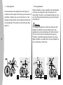
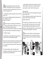
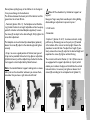
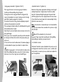
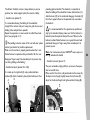
1
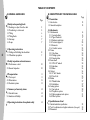
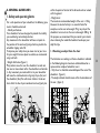
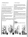
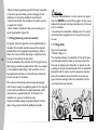
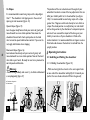
I n v a c a r e Action 3 NG ® ® Yes, you can. UK User guide Foreword The information contained in this manual is subject to change without notice. Some information is submitted under copyright – all rights reserved. Any information in this document cannot be photocopied or duplicated without prior written authorization by Invacare. As the European and world leader manufacturer of wheelchairs, Invacare endeavours to supply a wide range of wheelchairs to meet all the needs of the user in everyday life. However, final selection of the wheelchair rests solely with the user and his/her qualified health advisor. Proper and efficient use of the wheelchair that you have chosen is based upon the medical prescription which was issued for you on the basis of your pathology and the nature of your disability. Your wheelchair is especially designed to be used inside, and with certain restrictions outside. Please comply with traffic regulations. Stamp of the Distributor Introduction Dear Customer Thank you for purchasing an Invacare wheelchair. This model was designed to provide you with all the benefits and features to meet your needs. Only quality components were selected for your wheelchair based upon rigorous inspections during the entire manufacturing process. This manual describes the operating limits of your wheelchair, maintenance operations and adjustments that you or your assistant can make. However, all the repairs (except for inner tubes) as well as some adjustments, require specific technical training and, therefore, must be performed by your distributor. The Invacare Action 3 NG is designed for both indoor and outdoor use with the purpose of helping people who are not able to walk over a long distance. ® ® Even though your Invacare® wheelchair has been designed to provide a long and trouble free life it is inevitable that wear, tear and usage will eventually render the product unusable. Invacare® recommends that the average usable life of this product is five years, providing the product has been correctly maintained according to the manufacturers recommendations. 1 TABLE OF CONTENTS A. GENERAL GUIDELINES B. DESCRIPTION OF YOUR WHEELCHAIR Page 2 1. Safety and operating limits 1.1. Reaching an object from the chair 1.2. Transferring to other seats 1.3. Tilting 1.4. Tilting, Kerbs 1.5. Stairways 1.6. Slopes 3 5 6 6 7 7 2. Operating instructions 2.1. Folding and Unfolding the wheelchair 2.2. Wheelchair propulsion 8 9 3. Safety inspection and maintenance 3.1. Performance control 3.2. General inspection 10 10 4. Transportation 4.1. Test report 4.2. Observations 4.3. Restraint systems 11 11 12 13 5. Summary of warranty terms 5.1. Standard terms 5.2. Limitation of liability 14 14 14 6. Operating instructions for optimal safety 14 1. Presentation 1.1. Introduction 1.2. General description Page 15 15 2. Adjustments 2.1. Seat elements 2.1.1 Seat upholstery 2.1.2 Type of backrest 2.1.3 Backrest upholstery 2.1.4 Footrest supports 2.1.5 Armrests 2.1.6 Comfort version 2.2. Frame 2.2.1 Side frame 2.2.2 Folding system 2.2.3 Steering tubes 2.3. Rear wheel 2.3.1 24" & 22" wheels 2.3.2 Handrims 2.3.3 Axles 2.4. Castors 2.4.1 8" & 6" wheels 2.4.2 Front fork 2.5. Brakes 2.5.1 Manual brakes 2.5.2 Hub brakes 2.6. Seating options 2.6.1 Seat options 2.6.2 Propulsion options 2.6.3 Safety equipment and options 2.6.4 Other options 16 16 17 19 20 21 22 24 24 24 24 24 24 25 26 26 26 26 27 27 27 28 28 29 31 33 3. Specification and tool 3.1. Standard wheelchair specifications 3.2. Tools for adjustments and regular maintenance (Not supplied) 3.3. Dimensions 33 34 35 A GENERAL GUIDELINES 1. Safety and operating limits For a safe operation of your wheelchair, the following parameters should be observed : - Stability and balance Your wheelchair has been designed to provide the stability you need during normal daily activities. Any movement in the wheelchair will have an impact on the position of the centre of gravity, which may lead to the wheelchair tipping and a fall. To improve your safety when you move a lot or you transfer your weight from one place to another, we recommend using seat belts. - Weight distribution (figure 1) Many actions cause the user of a wheelchair to reach out, lean over or move about within the wheelchair and outside it. Any movement you make whilst sat in your wheelchair will move the combined centre of gravity of you (Gc) and the wheelchair (Gw).You will remain stable in the wheelchair whilst the line of your combined centre of gravity lies 1 within the points of contact of the forward and rear wheels with the ground. - Weight Limit The maximum recommended weight of the user is 125kg. However, the level of activity is an essential factor. For example, an active user who weighs 75 kg may subject the wheelchair to more stress than user who weighs 100 kg. To this purpose, we recommend that you consult your retailer when choosing the model of wheelchair based upon your daily life style. 1.1. Reaching an object from the chair The limitations on reaching out from a wheelchair indicated in the following diagrams have been calculated based on a representative sample of wheelchair users: - Only the arms should be extended beyond the seat of the wheelchair. (figure 2). - The body and head should remain within the boundaries of the seat. (figure 3). 2 3 3 1.1.2 Leaning backward 1.1.1 Leaning forward Do not extend your chest beyond the armrest (figure 4). In order to reach an object in front of you, you must lean and bend down ; therefore, you must use the castors as a tool (pointing them forward) to maintain stability and balance. An accurate alignment of the wheels is essential for your safety (figure 5). 4 4 5 Position wheelchair as close as possible to the desired object so that you can simply pick it up by stretching your arm while sitting in the chair in a normal position (figure 6). In any case, do not lean backwards because you may cause the chair to tip (figure 7). ! Warning : The hanging of back packs or similar items onto your chair backposts can affect the rearward stability of your chair, especially when used in combination with recliner backrests. This can cause the chair to tip backwards causing injury. Therefore, Invacare® strongly recommend the use of antitippers (available as an option) when using your backposts to carry a back pack or similar items. 6 7 1.2.Transferring to other seats 1.2.2 Front transfer (figure 9) 1.2.1 Sideways transfer If you are more or less able to stand up and if your upper body is strong and mobile enough, you can transfer forward to another seat. If you find this movement difficult, we recommend that you obtain some assistance from an attendant or carer to ensure the transfer is as smooth and safe as possible. This may be done without assistance provided that you are sufficiently mobile and have a strong enough torso. - Move the wheelchair as close as possible to the seat to which you would like to sit, with the castors pointed forward. Lock the wheels by applying the brakes. Fold the footplate up and push the footrest/legrest to the side, remove / swing away the armrest to falicitate the transfert. Shift your body towards the place where you want to sit while distributing your weight to the arms and hands (figures 8 & 8A). - While moving from the wheelchair to the seat, your body will have little or no support. Where possible use a transfer board during transfers. Lock both brakes and ensure both castor wheels are facing the forward position. Please note that the brakes should not be used in any case as support for transfers. Fold the footplate up, then grip firmly the armrest handle, take care of your nails on the skirt-guard edges. Push on your arms to easily lift yourself up and the attendant can help you to finalise the transfer to the place where you wish to sit. ! Warning : - Position yourself as close as possible to the place where you wish to sit. 8 8A 9 10 5 - When transferring, position yourself as far back as possible in the seat to prevent breaking screws, damaging the seat upholstery or causing the wheelchair to tip forward. - Lock the two brakes ; they should not be used in any case as support for transfers. - Never stand on the footrests when you are getting in or out of the wheelchair (figure 10). 1.3.Tilting (balancing on the rear wheels) 6 For greater safety, this operation must be performed by an attendant. The attendant should be aware of the required physical effort and use appropriate positioning in order to relieve the strain on his/her back (keep a straight back and bend your knees during this operation). To tilt the wheelchair, the attendant must firmly grab the handles making sure both are properly fixed. Warn the occupant in the wheelchair before tilting it and remind him / her to lean backwards and make sure that both feet and hands of the user are clear of the wheels. Place a foot on the footstep tube and move continuously until the chair reaches the equilibrium point. At this stage, the assistant will feel a difference in weight distribution, which usually occurs at approximately 30°. At this point, the wheelchair can get over the obstacle easily. Finally, the attendant slowly and gradually lowers the front down to the ground, while firmly holding the handles. ! Warning : - Be aware of detachable parts such as armrests or legrests : they must NEVER be used as lifting supports as they may be inadvertently released, resulting in possible injury to the user and / or attendant. - Do not lower the wheelchair suddenly, even if it is several centimetres from the ground, as this may result in injury of the user. 1.4. Tilting, Kerbs To get on the pavement : - Method 1 (figure 11) The attendant positions the wheelchair in front of the pavement facing forward. Press down on the lower tube of the frame (or on tipping levers, delivered as an option) as well as pulling on the push handles. Attendant tilts the wheelchair backwards until the castors reach the pavement; attendant pushes the wheelchair forward until the rear wheels are against the kerb and again pushes the wheelchair until the rear wheels climb over the kerb. 11 12 - Method 2 (figure 12) In this case, the attendant stays on the pavement and tilts the wheelchair in a backwards position with the rear wheels against the kerb. The attendant tilts the wheelchair backwards until it is balanced and pulls the wheelchair with a steady movement until the rear wheels climb over the kerb ; then he / she lowers the castors, while making sure that the chair is far enough on the pavement so that the castors do not fall into empty space. To get off the pavement : The attendant positions the wheelchair facing forward on the pavement and tilts it backwards until it is balanced, then he/she pushes the wheelchair forward until the rear wheels touch the road after getting over the obstacle; then, he / she gradually lowers the castors to the ground. 1.5. Stairways Because this is a difficult movement, we recommend using two attendants, one in front of the wheelchair and one behind the wheelchair. 13 ! Warning : we recommend that users over 100 kg in weight do not use this starway manoeuvre ! To climb stairways (figure 13) : After tilting the wheelchair to the point of equilibrium, one assistant (at the back) holds the wheelchair up against the first step grasping the handles firmly to lift. The second assistant, lifts the wheelchair above the stairs, while holding firmly a fixed part of the frame, and holds it while the first assistant takes a step and repeats the operation. The wheelchair must not be lowered until the last step has been passed and the chair is clear of the stairs. To descend stairways : Same operation as above, however, reverse steps as above. ! Warning : - Do not attempt to lift the wheelchair by any removable parts (such as armrests, legrests or footrests). - Avoid using an escalator which may lead to serious injury in the event of a fall. 14 7 1.6. Slopes It is recommended to avoid using ramps with a slope higher than 9°. The wheelchair risks tipping over in the event of spinning or side movement (figure 14). Upward slopes (figure 15) : Lean the upper body forward and your centre of gravity will move forward to a more stable position. Now move the wheelchair forward with short quick pushes on the hand rims to maintain speed and direction control. If you want to rest, apply both brakes when stopping. 8 Downward slopes (figure 16) : Lean backward cautiously and your centre of gravity will move backward to a more stable position. Now let the hand rims slide in your hands. Be ready to react at any moment to control speed and direction. ! Warning : - Avoid turning suddenly and never try to climb and descend a ramp diagonally (figure 17). The position of the rear wheel axle and the angle of your wheelchair’s backrest are two of the key adjustments that can affect your stability whilst sat in the wheelchair (see figure 14A). It is recommended to avoid using ramps with a slope greater than 9 degrees and do not attempt to turn whilst on a slope. The wheel position is usually factory set and should not be change unless by the direction of a competent person who must have assessed the impact of the change on your stability in normal use. If your wheelchair is fitted with a recliner backrest it is recommended that anti tippers are also fitted and used whenever the backrest is reclined from the upright position. 2. Operating instructions 2.1. Unfolding and Folding the wheelchair 2.1.1 Unfolding the wheelchair (figure 18) : - With one hand, grab the armrest or the seat support tube on one side of the wheelchair and slightly tilt it towards you (so that the rear wheel and castor lift from the ground) ; ex : Standard configuration for fixed backrest 14A 15 16 17 18 - With the other hand, push on the seat tube until upholstery is fully extended and seat tube sits in receiver. - Then, engage the two manual brakes, open the footrest/ legrest and check the ground clearance (footrest/ground distance - see paragraph B-2.1.4). You can now sit down in the wheelchair. 2.1.2 Folding the chair (figures 19 and 20) : - Fold and lock the footrest/legrest toward the front of the wheelchair. - Swivel the plates into the vertical position. Using both hands, take the centre front and back edges of the seat upholstery and lift it. Or, tilt the wheelchair to one side and close it using the handles on the backrest. ! Warning : - Fold the wheelchair while keeping the seat upholstery upwards to avoid damage by the folding system. - Caution possible finger pinch. 2.2. Wheelchair propulsion Self propelling wheelchair propulsion is achieved through the use of the handrims mounted on the wheels. The distance between the wheels axle position and the seat height can be adjusted to allow you to hold the handrims properly, and various accessories can be added to improve the grip (anti-slip plastic coated, etc.). Qualified medical and paramedical staff will be able to provide you with advice regarding the propulsion which is best adapted to your disability. Any wheels adjustments to the set up of your wheelchair (see paragraph 2.2.2) should only be performed at the direction of a competent person who has fully risk assessed the implication of any changes to the wheelchair configuration. 2.3. Lifting the wheelchair First, fold the chair (see paragraph 2.1.2), always lift the wheelchair by gripping the frame at the points (A) shown in the figure 21. ! Never lift the wheelchair by removable parts (armrests, footrests). Ensure the backrest posts are securely in place. A 19 20 21 9 3. Safety inspection and maintenance 3.2. General inspection 3.1. Performance control Your distributor, who has the required technical expertise, is responsible for any wheelchair repairs. We recommend that you take the wheelchair to your retailer at least once a year for a complete inspection. Regular maintenance allows the identification and replacement of defective and worn parts, which improves the daily operation of your wheelchair. As the user, you will be the first to notice any possible operational defects with your wheelchair. The following table indicates the easiest troubleshooting symptoms to identify and the preliminary inspection that you can perform. In the event that the symptoms persist after adjusting the pressure in the tyres, please consult your retailer. The inner tubes of the wheels are the only components that you can repair yourself (see paragraph B-2.3). 10 If the screws and nuts are not tight enough or loose, the axle fork angle is not perpendicular to the ground, please consult your retailer to get a competent person to re-set them to the correct position and tighten appropriately. (Recommended torque minimum : M5 = 4 Nm; M6 = 7 Nm & M8 = 17 Nm) The wheelchair swerves to the right The wheelchair swerves to the left The wheelchair turns or moves slowly The castors lift Creaking Play in the and clinking wheelchair Inspections Make sure that pressure in the pneumatic tyre is correct (cf. § B-2.3) Make sure that the bolts are tight Check the adjustment on the fork angle Make sure that the 2 castors come in contact with the ground at the same time Regular inspections to be performed by you or your assistants : a. General Make sure that the wheelchair folds and unfolds easily. Make sure that the wheelchair moves in a straight line. (no resistance or deviation) b. Manual brakes Make sure that the manual brakes do not touch the moving tyres. Make sure that the manual brakes operate easily. Make sure that the joints are not worn and do not have play. c. Folding system Check the folding system for worn or distorted parts. d. Skirtguard/armrest upholstery Make sure that all the fittings are properly tightened. e. Armrests Make sure that the armrests are firmly attached, but easy to remove. f. Armpad Make sure that the armpads are in good condition. g. Seat and backrest upholstery Make sure that the upholstery is in good condition. h. Rear wheels Make sure that the wheel nuts and precision bearings are tight. Make sure that the wheels are parallel to the frame. i. Handrims Check for rough patches. j. Spokes Make sure that the spokes are not distorted, loose or broken. k. Castors Make sure that the axle is tight by turning the wheel the wheel must gradually come to a stop. l. Fork/steering tube Make sure that all the fittings are well tightened. m. Pneumatic and solid tyres Check the pressure of the pneumatic tyres (Front=250 kPa, Rear=350 kPa) check the wear of the solid tyre tread. n. Cleaning and disinfection Cleaning: Use only damp clothes and gentle detergent. Do not use abrasive or scouring liquid. Do not use high pressure cleaning devices on ball bearings (front & rear wheels, fork axles). Make sure you dry the wheelchair if it is wet (e.g. after washing it or going out in the rain). Disinfection: Spray or wipe disinfection using a tested and recognised product is permitted. Please pay attention to the manufacturer's instructions of the medical product disinfectant you are using. 4. Transportation Transport of wheelchairs in vehicles The Invacare Action 3 has been tested for safety in collisions according to ISO-7176-19:2001, Invacare® Action3 can be used for transport in vehicles that have been specially adapted for this purpose. The wheelchair must be securely fastened in the vehicle according to the methods described on the following pages. ® ® Remember that the best solution is always to move the user from the wheelchair into a normal car seat and to stow the wheelchair safely and securely in a separate compartment. Test no : P500846A (fixed backrest) & P5000846B (recliner backrest), Customer : Invacare Rea AB, Date : 2005-01-21 The safety restraint devices used in this test must be approved according to ISO-10542. We have chosen to work with Unwin, a well-known quality manufacturer of safety restraint devices for wheelchairs. Restraint system manufacturer may improve its products, please contact them for more details. 11 4.1. Observations before transport of wheelchairs in vehicles 12 • We recommend that wheelchair users should transfer to the seat of the vehicle and use the installed restraint system of the vehicle whenever feasible. • The wheelchairs are tested in a basic configuration. The use in other configurations has not been tested. Please contact your dealer for further information. • Auxiliary wheelchair equipment is either secured to the wheelchair or removed from the wheelchair and secured in the vehicle during transit. (i.e. table trays). • Alterations or substitutions are not to be made to points of the wheelchair or to structural and frame parts without the written consent of Invacare®. • A wheelchair-anchored posture belt with metal buckle must be fitted across the wheelchair occupant in addition to the lap and diagonal occupant restraint (3-point belt). • Belt restraints are not to be held away from the body by wheelchair components or parts such as armrests, postural restraints, wheels, etc. (Picture 22) • The wheelchair must be securely fastened in the vehicle with an ISO 10542-2 approved 4-point belt system, according to the methods described in the manual. • The occupied wheelchair must be tied down in an forwardfacing position, with the parking brake applied. • The wheelchair backrest should be positioned as close as possible to 90 degrees. Please observe that even if these products and recommendations are provided in order to increase safety, injury to vehicle occupants still might occur in the event of a collision or other accidents and no guarantee is given in this respect. Correct and incorrect placements of 3-point belt (picture 22). 4.2. Restraint systems (pictures 23A & 23B) * Non contractual picture, only for information ! Please refer to best practice recommended instructions from the safety belt manufacturer. A. Front restraints with straps (picture 23A) 1. Connect the front straps around the frontal part of the frame. (See location of the attachment labels). 2. Release brakes and apply tension front straps by pulling the wheelchair backwards from the rear. 3. Re-apply wheelchair brakes. B. Rear restraints (pictures 23A for self propelling & 23C for Transit version) 1. Attach the snap hooks on the rear straps to the frame just above the rear wheel attachments. (See location of the attachment labels). 2. Tighten the straps. C. Posture belt 1. The posture posture belt is mounted on the back frame (picture 24). 2. Check that the posture belt on the wheelchair is correctly fastened. If posture belt on the wheelchair is missing we recommend that the user should transfer to the seat of the vehicle, if possible. The posture belt should be used in addition to but never as a substitute for an approved passenger restraint system (3-point belt). D. Fastening of 3-point belt (vehicle safety belt device). Although all three points may be anchored to the vehicle floor, the diagonal belt passing over the users shoulder should be routed through a point above and behind the seated user which is fixed to the vehicle sides, before passing down to the floor. The 3-point belt should not be kept from the user's body by the parts of the wheelchair. B 22 D 13 23A C A ���������� 23B 23C 24 5. Summary of warranty terms 5.1. Standard Invacare terms and conditions 14 This is to certify that your manual wheelchair is warranted by Invacare for a period of 2 years for the frame and crossbars, all others parts 2 years also but subject to the following conditions : - If a defect or fault is discovered the supplier / dealer from whom the appliance was purchased should be notified immediately. - The manufacturer will not accept responsibility for damage caused by misuse or non-observance of the instructions set out in the user manual. - During the period of warranty, any parts that have become defective due to faulty workmanship or materials, will be renewed or repaired without charge by the Invacare dealer/ supplier. - The warranty will be forfeited should any unauthorised alteration be made to the equipment. - The Purchaser’s statutory rights under the Consumer Protection Act are not affected. 5.2. Limitation of liability This warranty does not extend to the consequential costs resulting from fault clearance, in particular freight and travel costs, loss of earnings, expenses, etc. Invacare shall not be liable for : - Natural wear and tear. - Inappropriate or incorrect use. - Defective assembly or setting-up by the purchaser or third parties. - Defective or neglectful treatment. Use of unsuitable spares. 6. Operating instructions for optimal safety - Maximum user’s recommended weight : 125 kg. - Do not attempt to reach objects if you have to move forward in the seat. - Do not attempt to pick up objects from the floor by reaching down between your knees. - Do not lean over the top of the upholstery back to reach objects located behind you : this may cause you to tip over - Always engage both manual brakes simultaneously. - Manual brakes are parking brakes : they must not be used in any way to slow down the wheelchair or as support during transfers. - Do not tilt the wheelchair (down kerbs or steps) without using an assistant. Press down on the lower tube of the frame as well as pulling on the push handles - Do not carry the wheelchair up or down stairway or escalators with the user seated in the wheelchair, with only one attendant. This may cause serious injury. - Do not use the wheelchair unless it has the proper tyre pressure (front = 250 kPa, rear = 350 kPa). - Do not overinflate the tyres : this may cause the tyres to explode and cause bodily harm. - Do not expose the wheelchair to a temperature higher than 40°C. - To avoid injury, keep your fingers away from mobile parts (armrests, folding system, legrests/footrests), and maintain good posture before lifting the wheelchair. ! Avoid operating on wet areas as well as gravel, grass, etc. (sand and sea water particularly damage ball bearings). When using the wheelchair inside, we recommend using solid tyre castors, especially when riding on carpet. 1.2. General description (see photo) B. DESCRIPTION OF YOUR WHEELCHAIR 1. PRESENTATION 1.1. Introduction Your wheelchair is made of various parts and this manual describes only the main parts. We recommend that you become acquainted with the following terms in order to better understand your wheelchair operation : The seat consists of the seat and backrest upholstery, the backrest and armrests. This unit is designed to provide optimal comfort. Your wheelchair has been factory set before you purchased it. However, it must be specifically adapted to your needs. The following detailed paragraphs describe the various functions and possible adjustments as well as available options. You can make some adjustments yourself, while others can be made only by your dealer. Important: based upon the selected model or options, your new Invacare Action 3 NG wheelchair may be not equipped with all of the components or options which are described in the following pages. ® ® NB: Some models or options are not be available in your country. ! This is a warning symbol, it is essential that the instructions in these paragraphs are followed in order to prevent personal injury to yourself and others around you. iThis is an information symbol about possibility to contact your Dealer for more information. The swing-away footrest support or legrest : this is the supporting part between the frame and the footrest which swivels to facilitate transfers and can be removed during transport. The footrest consists of an adjustable tube and the footplate which supports the foot. The folding frame consists of side frames and a folding system including the seat rails. These parts constitute the frame, which is the supporting component of the wheelchair and its strength is well tested (checked at 125 kg). The steering tube is the connection between frame and castors ; it allows the adjustment of the seat angle. The rear wheel consists of the wheel, axle and handrim. The position of the rear wheels relative to the seated user determines the rearward stability and also the ease by wich the user can propel the wheelchair using the handrims. They are mounted on the multiple adjustment wheel support brackets. 15 Changing the rear wheel position will have a significant impact on the stability of the user. The castor consists of the front wheel and the fork. The castors provide front contact with the ground and determine the steering by the direction of the forks. 2. Adjustments The manual brake is a parking brake. The two manual brakes are used to secure the wheelchair when stationary. • Nylon upholstery seat with or without Velcro fastener : the Velcro fasteners are required for the proper positioning of the cushion (photo 1) ; please make sure that the cushion is properly positioned on the seat. Armrest Backrest 16 Seat upholstery Rear wheel Rear wheel support Swing away legrest Rear wheel axle 2.1.1 Seat upholstery - Standard seats • Padded seat : it provides comfortable support to the user. Armpad Backrest upholstery 2.1. Seat Adjustable footrest tube i Standard seats are not adjustable; in the event that they become slack, it is recommended that you ask your dealer to replace them. ! Always use upholstery equipped with Velcro fasteners when you have a cushion in order to prevent sliding. Adding a cushion to the seat will raise your height above the ground and can affect your stability in all directions. If a cushion is changed it may also change the users stability. i Invacare provides a wide range of seat cushions adapted to your needs. Please contact your dealer. Handrim Manual brake Footplate Folding frame Steering tube Front wheel Swing away footrest 1 - Rigid seats : • Comfort and toilet seats (photo 2) : they are removable allowing the folding of the wheelchair, simply lift the seat and put it away, then take hold of the 2 seat rails and pull them upwards. Repeat the operation in reverse order to unfold the wheelchair (see paragraph 2.1.1). i The upholstery and casing of the two seats will wear, please contact your dealer for possible replacement. ! Make sure that the seat is properly positioned on the 2 seat rails to provide safety and comfort for the user. Keep your fingers away from movable parts to prevent injuries during folding and unfolding ! 2.1.2 Type of backrests The 7° version can be optionally equipped with height adjustable push handles which provide better comfort to the attendant (photo 3); loosen the knob (A), moves the push handle to the required position and retighten the knob (A) firmly. When raised to the maximum height a spring loaded pin will locate in a hole hidden beneath the upholstery just below the knob (A). To lower the push handle from the maximum height first loosen knob (A), then press on the pin through the upholstery and lower the push handle. ! Make sure push handles are locked fast before use ! Don’t raise push handles to maximum height when tilting the chair. For best practices, please refer to paragraph 1.4.1. Tilting, Kerbs, for the safety instructions. 17 - Fixed backrests : - Folding backrest (photo 4) 43 or 51 cm backrest height. • Fixed backrest of 0° and 7°; these two backrests do not require adjustments, they can be equipped with padded backrest or contour (tension) adjustable backrest (optional, see paragraph 2.1.3). • To save space when transporting folded and unoccupied, operate lever (A) by pulling or pushing it and fold the top of the backrest. To return to the initial position, bring the top in the vertical position; it locks automatically. A A 2 3 B 4 ! Always make sure that the backrest is properly locked in place before the user settles down in the wheelchair to prevent any injuries ! - Reclining backrest 0° - 30° - 43 cm (short cane tube) or 51 cm (long cane tube) backrest height. 18 The intended use of reclining backrest is to get a relaxing, comfort position for the user. It is not indented to be used in a dynamic situation and it should be used on horizontal surface when the backrest is reclined (especially when the backrest angle is more than 10°). Anti-tippers are recommended for those who need to feel safer or have a specific usage. Simultaneously pull the levers (A) to provides the same angle on both sides, release the levers when you reach the desired angle.(Photo 5) Mechanical version Note : Push on the backrest canes before operating the levers, this is to release the auto-locked security system. (Photo 5A). Gas strut version 0° to 30° continuously (photo 6). The gas struts provide a help to the attendant to raise the user, always operated with the user seated in the wheelchair. ! It is recommended that this operation be performed only by the attendant. Always make sure that the backrest is locked in place to ensure perfect safety for the user. Keep away fingers from moving parts (levers, cylinders, mechanisms, etc.) to prevent injuries ! The backbrace (B) (photos 6 & 6A) links the two push handles and must always be in position on recliner versions (see paragraph 2.6.1). Avoid operating levers (A) (photo 6) during a sideways transfer, for example, in order to prevent destabilising the user’s position ! ! if you consider there is an excessive free play in the recliner mechanism after a simple visual examination of the ratchet, please contact your Dealer. There are 4 angles position by step of 10°. 1 2 5 A 5A A B 6 B 6A To ensure safety for the user, when backrest is reclined, we recommend to use anti-tippers (available as an option). use. Please contact your Dealer. Based upon the development of your disability, you can 3 choose an Action backrest that meets your needs. Please consult with your Dealer. ! The hanging of back packs or similar items onto your chair backposts can affect the rearward stability of your chair, especially when used in combination with recliner backrests. This can cause the chair to tip backwards causing injury. Therefore, Invacare® strongly recommend the use of antitippers (available as an option) when using your backposts to carry a back pack or similar items. • Fixed backrest with mid-height angle adjustment (photo 6B); 2.1.3 Backrest upholstery i Maintenance of reclining backrest mechanism varies with The angle can be adjusted using the different holes on the backrest support (shema 6C), remove screw (A) and nut (4 mm Allen key and 10 mm spanner), select the desired angle (from -6° to + 24°, every 6°), repositioning the screw (A) and firmly re-tighten. The push handles are height adjustable, slightly loosen the knob (B), adjust to the desired height, firmly re-tighten. ! Always make these adjustments before the user settles down in the wheelchair to prevent injuries ! _ 6B +18° A 6C • The padded backrest provides excellent daily comfort for the user who does not need specific support for the upper body. i In the event that the upholstered backrest slackens, ask for a replacement from your Dealer. • Contour (tension) adjustable backrest (photo 7 & 7A); Contour allows adjustment of the backrest curvature based upon user’s body posture, to provide the best comfort as possible. + +24° B - Standard upholstery backrests B +12° +6° A A 0° C -6° 7 B 7A 19 ! Before making adjustments please ensure that the wheelchair is fully opened, the seat rails are properly located and a back brace (C) is perfectly fitted on the chair (see instructions paragraph 2.6.1). - Lift the flap (A) and pull the strips (B) in order to stretch or slacken them. Each strap can be individually adjusted to provide best comfort as possible to the user. Reposition the flap (A) ! 20 Check the quality and positioning of the Velcro fasteners. Always make this adjustments before the user settles down in the wheelchair to prevent injuries ! The backrest tubes could be bent inwards by over tensioning the straps and/or failing to fit the backbrace (see photo 7). 2.1.4 Footrest supports - Standard footrest supports (photo 8) swing away during transfers and can be removed during transport. Operate lever (A) by pushing sideways and swivelling towards outside or inside in case there is not enough space. To return to the initial position, align the footrest support it locks automatically. To remove the footrest support, simply pull up after unlocking the assembly. Reverse the procedure to reassemble, while still in the unlocked position. - Legrest (photo 9) performs the same operation as for the footrest support to swing away or remove the legrest, by operating lever (A) which unlocks the locking system. Angle adjustment Pull the lever (B) with one hand while supporting the legrest with your other hand. When a suitable angle is obtained, let go of the lever and the legrest will look into one of seven preset positions (schema 9A). The calfpad swings away during transfers and have 3 height adjustment options. After loosening the screw (C), adjust to the desired height and firmly tighten the screw (C). In addition, it is depth adjustable loosen the screw (D), bring to new position and firmly tighten the screw (D). ! Take care of the stability by using elevating legrests and reclining backrests on the same chair. Lowering the legs before raising the backrest could make the wheelchair unstable. B A 8 9A A D C 9 Do not place anything heavy, or let children sit on the legrest. It may cause damage to the mechanism. The distance between the lowest part of the footrest and the ground must be at least 40 mm. - Footrests (photos 10 & 11) : the footplate can be lifted during transfers footrests are height adjustable and can be equipped with a fixed or articulated footplate (optional). Loosen the screw (A) to adjust to the desired height, firmly tighten the screw after adjustment. The footplate can be articulated by indexed plate (optional) loosen the screw (B), adjust to the desired angle and tighten securely. - Straps : to ensure a good position of the feet, two types of straps can be provided; the heelrest strap (plain or adjustable by Velcro fasteners) and the calfpad strap attached to the footrest support are both adjustable by Velcro fasteners. Note : the standard footrest supports and legrests are mounted in pairs on the wheelchair; whenever you remove them, remember that you have a right side and a left side ! A ! Never lift the wheelchair by the footrest supports or legrests ! Keep your fingers away from movable parts during folding, disassembling or adjustment to prevent injuries ! 2.1.5 Armrests - Removable : • Simple n°1 (photos 12 & 13) : to remove armrests, simply pull them up. Previously, press on the push pin (C) located at the bottom of the armrest vertical upright. Reverse the procedure to reinstall them. To adjust their height (3 positions), remove the screw (A), adjust to the desired height and reposition the screw (A), tighten without forcing. The armrests with central fixation (n°1 & n°4) from now on are equipped with a support adjustable (in 2 parts) which enables you to reduce the plays and to facilitate the vertical tube extraction, it is necessary to tighten or loosen the 4 screws (B) according to the anticipated result (photo 13). A A C 10 B 11 12 B 13 21 22 - Swing-away, removable n°2 (photos 14 & 15) - Ajustable tubular n°3 (photo 16) : This range of armrests can be swung away to facilitate transfers and disassembling during transport. To swing the armrest away, push down the dog point (A), reverse the procedure to reinsert making sure that the dog point (B) is properly engaged in its housing. To remove the armrest, swing it back completely and pull it up. Reverse the procedure to reinstall. The new design includes handle (C) and hollowed skirt-guard (D) to facilitate front transfer. Grip firmly the armrest handle, take care of your nails on the skirt-guard edges. Push on your arms to easily lift yourself up and the attendant can help you to finalise the transfer to the place where you wish to sit. In the event the armrest handle covers (C) become slippery, it is recommended to request your dealer to replace them. Identical to the previous procedure including armrest height and depth adjustment ; slightly loosen the ball screw (B), adjust for the desired height based upon the preset holes and firmly tighten the screw ; slightly loosen the two screws (C) and slide the armrest down for the desired depth, firmly tighten the two screws (C). ! Refer to paragraph 1.2.2. Front transfert for safety instructions. When folding back down, ensure that it locks in place, otherwise it can act as a long lever and could fatigue. A B C Note : the armrests are mounted in pairs on the wheelchair ; whenever you remove them, remember that you have a right and a left side ! ! Never lift the wheelchair by the armrests ! Keep your fingers away from movable parts during folding, disassembling or adjusting to prevent injuries ! 2.1.6. Comfort version The Action3 Comfort version (wheelchair for passive user) is not designed or tested to be used as a seat in a vehicle (not crash tested) it is necessary to use a vehicle seat adapted to yout transportation. C D 14 15 B 16 1 17 The Action3 Comfort version is always delivery in passive position (rear wheel support plate) for a better stability. - Comfort seat (photo 17) It is removable allowing the folding of the wheelchair ; simply lift the cushion and put it away, then grab the two seat holding tubes and pull them upwards. Repeat the operation in reverse order to unfold the wheelchair (see paragraph 2.1.1). iThe padding and outer cover of this seat will wear; please contact your dealer for possible replacement. Make sure the cushion is properly positioned on the 3 seat Velcro fasteners to provide safety and comfort for the user. providing optimal comfort. The backrest is removable to allow the folding of the wheelchair; loosen both buttons (C), slide the levers (D) to the inside and disengage the hooks (E) from their supports. Reverse the procedure to reassemble the backrest. ! It is recommended that this operation be performed only by the attendant. Always make sure that the backrest is locked in place for optimal safety of the user. Make sure the backrest cushion Velcro fasteners are in good state and well positioned. Keep your fingers away from movable parts to prevent injuries. Note : for maintenance of your DARTEX® cover, only use a soft rag soaked with alcohol. Keep your fingers away from movable parts to prevent injuries during folding and unfolding ! - Comfort backrest (photos 18 & 18A) It is made up of a rigid shell (A) and a preformed foam cushion (B) which is locked in place by Velcro fasteners thus B A - Comfort armrests (photo 19) They are removable, simply pull them up; reverse the operation to reinstall them. Make sure that the slot is well positioned into the screw (A). To adjust armrest height, slightly loosen the ball screw (B), adjust to the desired height and tighten without forcing (B). C D B E 18 18A C D A 19 23 Armrest pads are depth adjustable : slightly loosen the ball screw (C) and slide the pad to the desired depth, tighten firmly (C). 2.2. Frame Note : the adjustment of the side protection is required based upon the desired height; slightly loosen the screws (D) and slide the unit to the new position, tighten firmly (D). It is possible to choose 5 extra positions with screw (A); loosen the nut and position the screw in the new hole. Tighten firmly (A). It consists of two cross-bars which integrate seat rails. - Comfort headrest (photo 20) 24 It is removable, completely loosen the ball screw (A). It is height adjustable, slightly loosen the ball screw (A), adjust to the desired height, tighten without forcing. The cushion also is angle, depth and height adjustable by operating simultaneously the lever (B) and screws (C). Note : make sure that the indexable lever is properly oriented to prevent any bother or injury to the user or attendant. ! Do not adjust the head rest when the user leans on it and check the mounting to the backrest in order to prevent injuries. C B A 20 2.2.1 Folding system To fold and unfold your wheelchair, see chapter A “ General ” paragraph 2.1. 2.2.2 Side frame The sides or side frames are designed to accommodate the steering tubes for the castors and multiple adjustment wheel mounting for rear wheels. - These wheel mountings allow five height positions and three longitudinal positions (Active = advanced for better handling; Standard = serial delivery with fixed or folding backrest; Passive = backward for better stability, serial with reclining backrest and Transit (12”) version). ! The above information is given to the user for information only. Any wheels position and/or angle fork adjustments to the set up of your wheelchair should only be performed at the direction of a competent person who has fully risk assessed the implication of any changes to the wheelchair configuration. Please consult your dealer. 2.3. Rear wheels 2.3.1 24" & 22" wheels The 24" (610 mm) rear wheels are spoked or composite wheels; the 22" (550 mm) wheels are only spoked wheels. They can be delivered with pneumatic or solid tyre. 2.2.3 Steering tubes The 24" spoked wheels can optionally accommodate spoke guards to prevent injuring the fingers during propulsion. A flat tyre (photo 21) must be removed in order to be repaired. Remove the rim assembly (tyre and inner tube), repair or replace the inner tube, reinsert in the tyre and reposition the assembly on the rim. They provide seat dump (0°, 3° or 6°) based upon user’s capacity, propulsion, desired floor-to-seat height and selected front and rear wheels. Comply with the inflation pressure specified on the sidewall of the tyre. - Dual amputee position (option or accessory): to prevent back tip with Amputee user’s, the rear wheel axles can be positioned backwards from the backrest cane axle (specific manual brakes are included in the kit) for a better stability. i All these adjustments and changes of position must be performed by a professional technician upon agreement by your prescribing physician. Please consult with your dealer. Note : remember that in order to maintain the interchangeability of the chair wheels equipped with quick-release axles, the pressure in the two tyres should be the same. ! In "Active" position, the manual brake may unlock after swinging the footrest support out. In this particular case, we recommend to swing the footrest support inside ! Active position is only compatible with 6'' front castors. In "Active" position, it is necessary to use anti-tippers to avoid any risk of tipping backwards when you drive on a slope ! (See paragraph 2.6.3) 21 25 ! Check and adjust the brakes to ensure they are still correctly positioned and function as required. ! Never exceed the pressure specified on the sidewalls of the tyre, otherwise, the tyre may explode and cause injuries ! i Pneumatic tyres wear out. In addition, the roughness of the ground surface and driving have an impact on their longevity. Replace them regularly to avoid punctures caused by puncture. Please consult with your Dealer. 26 2.3.2 Handrims They provide the wheelchair propulsion. They can be made of anodized aluminium or coated with nonslip plastic (optional). ! Handrims are constantly in contact with your hands. Make sure that they are not damaged ! B A D C 2.3.3 Axles The axles connect the wheels and frame. Fixed and quick-release axles are available - Fixed axles: regularly check the axle tightening. - Quick-release axles (photo 22) : depress the button (A) and insert the axle in the wheel hub. Position the assembly in the bearing (B) of the multiple adjustable wheel mounting until it locks in place. The locking balls (C) must rise above the bearing. No significant side clearance is allowed. To reduce clearance as much as possible (photo 23), remove the axle and adjust the nut using a 24 mm key ; then block the axle with an 11mm open-end key. ! Make sure that the axle and the locking balls are clean. (wipe out every month with a rag soaked with fine oil) To prevent falls, it is essential that the button (A) and the locking balls (C) are disengaged providing a perfect lock of the rear wheels. The quick release axle is a precision part, take care of shocks and clean regularly to ensure the good working of the mechanism. A 22 23 2.4. Castors 2.4.1 8" & 6" wheels The front wheels are available in 8" (200mm) diameter and in two widths, 1 3/8" (32 mm) and 2" (50mm), or in 6" (150mm) diameter and a single width of 1 3/8" (32mm). They can be delivered with pneumatic or solid tyre. Note : refer to paragraph 2.3.1. for regular maintenance. 2.4.2 Forks Different fork positions are available based upon the selection of floor-to-seat height, castors and rear wheels. Note : brake adjustments are based upon the diameter and type of the wheels. After repairing a flat tyre or in the event of wear of the pneumatic or solid tyre, you may need to adjust the brake(s). To adjust the brake(s), loosen the two screws (B) and slide the brake assembly to obtain the following value between the wheel and the brake shoe in unlocked position (photo 25) ! Please make sure this adjustment is always done as describe whatever the chair configuration is. Solid tyre X = 6 mm, Pneumatic tyre X = 5 mm ! Firmly tighten the screws (B) after adjustment. Keep your fingers away from movable parts to prevent injuries ! 27 i Please take advice from your dealer, if you want to replace a fork or the castors or rear wheels. 2.5. Brakes 2.5.1 Manual brakes A The manual brakes (photo 24) are designed to secure the wheelchair during long stops. They are not intended to slow down the wheelchair or to be used as support during a transfer. They must be operated simultaneously. In order to brake, push the handle (A) forward. The handle folds back to facilitate transfers. Draw as a preliminary the handle upwards ! Once the brakes are engaged, the wheelchair should not move at all. B X 24 25 28 2.5.2 Hub brakes 2.6. Options Besides the functions provided by manual brakes, the hub brakes provide the slow down (for example, on a slope) and improved safety because they are still efficient when you have a flat tyre ! 2.6.1 Seating options Two versions are available: (photos 26 & 27) attendant control and dual control (attendant and user). To slow down, gradually pull the lever (A) upwards. To lock the brake in parking position, with the lever (A) tightened, push the lock (B) to engage it in the notches of the brake handle ; then pull the lock up to unlock. To adjust braking : turn the screw (C) counterclockwise to increase braking force and turn clockwise to reduce it. This mounting allows you to adjust the height, angle and sides using a two levers (A & A') ; the cushion is also angleadjustable by operating the lever (B). i The specific adjustments of hub brakes must always be performed by your Dealer. - Anatomic headrest (photos 28 & 29) : it is mounted on the back brace (described below) by means of a multiple adjustment mounting. Note : make sure that you properly position the indexable levers so that they are not in the way or causing injury for the user or attendant. ! Do not adjust this option when the user leans over and make sure that their mounting to the backrest is correct to prevent injuries. ! Always operate the two brakes simultaneously and do not take slopes exceeding 5° to ensure perfect control of the wheelchair steering ! 28 C B B A A' 26 27 A 29 - Back brace (photo 30) : it provides tension to the backrest upholstery and provides the attendant better ergonomics when pushing the wheelchair. 2.6.2 Propulsion options Note : it swings away to facilitate the wheelchair folding; slightly loosen the button (A), pull up and swivel along the backrest until it is in vertical position. - Transit version (photos 32 & 33) : the wheelchair is designed to be driven only by the attendant. To facilitate sideways transfers and save space, the wheelchair is equipped with rear wheels of 12" (315 mm) with pneumatic or solid tyres. To reposition it, reverse the procedure and firmly tighten the button (A) making sure that the button is properly tighten (B). Note : Transit version equipped with a reclining backrest is always fitted with anti-tippers. ! It is important to ensure that the backbrace is correctly fitted and engaged at all times when the chair is in use. (see label on the backbrace) (photo 31). Do not lift the chair by handling the back brace. There is a risk to unlocked the back brace by push it up. Keep your fingers away from movable parts to prevent injuries. B The manual brakes (optional hub brake) are only accessible to the attendant; operate the handle (A) to lock the wheelchair in parking position. Note : for further information about the use of the two types of brakes, see paragraphs 2.5.1 & 2.5.2. A A A 30 31 32 33 29 30 - One arm lever drive (photos 34 & 35) : this control system(left or right hand) allows the user with low muscular tone to propel the wheelchair. Using one arm through the lever pendular motion which propels it forward or backward (reversing lever A) and which integrates steering and braking. - Dual handrim DHR (photos 36 & 37): The lever can be removed to facilitate transfers or to move next to a table ; loosen the indexable lever (B) and pull up. Reverse the procedure to reinstall. 1. The removable and interchangeable rear wheels facilitate transport as well as change of the control side. To dismantle the wheel, pull the button ( A ) and remove the wheel from its support. The adjustment of the propulsion force is performed by moving the transmission link on the pendular motion lever ; slightly loosen the indexable lever (C), slide down to reduce the stress, and firmly tighten the lever (C). ! To prevent falls and injuries, it is essential that the button (A) is fully engaged providing perfect locking of the rear wheels. ! The manual brake is always located opposite to the control. Make sure that the indexable levers are properly positioned so that they are not bothersome or hurtful for the user and attendant. This new quick release system allows the user to drive the wheelchair with a single arm using two handrims on the same wheel with 2 possible side positions of the small handrim (right or left available). 2. Two positions of the small handrim are possible to facilitate the propulsion: 1) internal position 2) external position Unscrew the three fixation bolts (B), position the small handrim depending on the needed configuration, firmly tighten the three bolts. A B C 34 35 B 36 A C B 37 To fold the wheelchair, take the transmission shaft (C) off by sliding one part inside the other. To facilitate this operation move the small handrim forwards to backwards.You can now roll the folded wheelchair. ! Please note that the transmission shaft is an integral part of the wheelchair and the user will be unable to propel the wheelchair without it. 2.6.3 Safety equipment and options - Safety standard equipment : Ensure you are sitting correctly, i.e. fully back in the seat, and the pelvis is as upright and symmetrical as possible - not forward on one side or tilted back. Position the posture belt so that the hip bones can be felt above the belt. As a guide, adjust the length so that there is just sufficient room for your hand to slide between your body and the belt. For ease of use it is recommended that the clasp is kept in a central position where possible i.e. make adjustments to each side of metal buckle belt with double adjuster. Please check your posture belt every week, to ensure that it is in good condition; no damage, fraying etc. and that it is securely fixed to the wheelchair. • Velcro fastener (photo 38) : position the two Velcro strips one over the other based upon the user’s build. ! In case the posture belt has to be replaced, the new belt fixation should be conform to the scheme enclosed with each belt delivery; the belt should be mounted and adjusted by your regular dealer. • Buckle fastener (photo 39) : to close the buckle, engage part (A) into part (B), to open press (C). Make sure that the belts do not get caught in the spokes of the rear wheel. Straps should be adjusted to suit user, insert into part (B) of the buckle and adjust the loop (D) based on the remaining length. The posture belt must not be used as a 3-point belt in a car. Posture belt C B D A 38 39 - Safety optional equipment : Anti-tippers (photo 40) : prevent back tipping which ensures safety when using a reclining backrest, driving on slopes or crossing obstacles. These are removable : push down the button (A) and pull back. Reverse the procedure to reinstall. Make sure that the dog point (B) protrudes over the frame tube. 31 Anti-tippers with tipping lever (photo 41) : prevent back tipping which ensures safety when using a reclining backrest, driving on slopes or crossing obstacles. It is height adjustable and also act as tipping lever (see paragraph Tipping lever) Anti-tippers can remain in place when the wheelchair is not used; perform a half-turn by activating the button (A in figure 42 & B in photo 40) and rotating. Tipping lever (photo 43) : it allows the attendant to easily tip the wheelchair when crossing an obstacle (pavement, step, etc.) ; push down the lever with your foot (right or left) and maintain balance using the push handles. The tipping lever is mounted the same as the anti-tippers, in the same tube. Note : Make sure that the anti-tipper wheel is ALWAYS located out side the rear wheel volume. All these adjustments and changes of position must be performed by a professional technician because these can affect the stability and the safety of the user ! Please consult your dealer. ! The recommended distance between anti-tippers small wheels and floor is 3 to 5 centimetres ; this adjustment is required with reference to the position and diameter of the rear wheel. 10 32 m m Push down the button (C in photo 40 & A in figure 42) and adjust the wheels holding tube for the desired distance based upon the preset holes. ! Make sure that the dog points locates in and protrudes through its appropriate location hole in the frame tube in order to prevent any falls. A A C C B 40 42 41 ! ! 3 cm mini 43 2.6.4. Other option 3. Specifications and tool - Transparent tray (photo 44) : it is positioned on the armpads of the armrests (full length ones only). Slide the tray forward or backward based upon the user’s build. 3.1. Standard wheelchair specifications ! Do not place very heavy and unstable objects, containers with very hot and corrosive liquids on the tray, which may cause serious injury if they fall. 44 Maximum user weight : 125 kg Seat width : 38/40,5/43/45,5/48/50,5 cm Seat depth : 40/45 cm Floor/seat height : 51/48,5/46/43,5/41/38,5 cm Rear wheel : 24" (610 mm) pneumatic tyre Castors : 8" (200 mm) solid tyre Parking brake : Manual brake with indexed brake shoe Backrest : Fixed, folding reclining Armrests : Removable, removable and swing-away Footrest supports & Legrests : Removable and swing-away Seat upholstery : Black nylon on reinforced upholstery Frame : Aluminium, epoxy coated Wheelchair average weight : 14.5 kg 33 3.2.Tools for adjustments and regular maintenance (not supplied) 34 Function Tool Brake Footrest tube Footplate Adjustable armrests Simple armrests n°1 5 mm Allen key 5 mm Allen key 5 mm Allen key 5 mm Allen key 4 mm Allen key 10 mm open-end wrench T20 Torx key 13 mm open-end Wrench(X 2) 24 mm open-end wrench(X 2) 19 mm open-end wrench 11 mm open-end wrench Armpad Castor Rear wheel fixed axle Quick-release axle After sale and disposal recommendations • It is compulsary to use original Invacare spare parts which you can buy through any Invacare dealer. • For repair, please contact your local Invacare dealer. • Disposal : the metal parts can be disposed of for scrap metal through recycling. Plastic parts are disposed of as plastic scrap. Disposal must be carried out in accordance with the respective national regulation. Please apply to your municipal authorities/local government for details about local disposal companies. ® ® ® 3.3. Dimensions Picture ������� Description Min/Max value Seat effective width (mm) 380/505 Overall width (mm) Width of folded wheelchair (mm) 570/695 285 Total height (mm) 815/1020 Height from ground to back seat (mm) 360/510 Height from ground to front seat (mm) Backrest height (mm) Wheelchair height when backrest is folded (mm) 385/510 400/510 625/750 Picture Description Backrest height including headrest (mm) Min/Max value 1045/ 1290 Overall lenght (mm) 1000 Lenght without footrest (mm) 717/857 Distance between front wheel and rear wheel (mm) 362/550 Backrest angle ( 0° ) 0/30 Bracket angle ( 0° ) Distance between footrest and seat (mm) Distance between armrest and backrest (mm) 80 ����������� ������� ����� ������������� ������ ����� 200/260 ������� �������� ������ ����� ���������� ������� ����������� 190/295 ������� ���� ����� ������ ������� ������� ����������� 130 ������� �� ����� ������ 9 ���������� �������� ����� 560/610 ������� ������� ��������������� ������ 17 ������� ����������� ������� ����� 128 17 ������� �������� ����� 470/520 ��������� ����� Wheels Armrests Footrests ���������� ����� ����� 0/6 ������� ������ ���������� ������ 14,5 ������ ������������ ����� ����� 660 ������ ������� ������ ������ 125 8,5 Nylon:M4 BS EN 1021 1/2 350/480 ������� ������ ���� 870 ������������� �������� ������������ ������ 250/350 ������� ����� ���� 50 ������������� ���������� 35 36 37 Invacare France Operations SAS Route de Saint Roch - 37230 FONDETTES ® Yes, you can. Invacare Australia Pty Ltd. 1 lenton Place, North Rockes NSW 2151 Australia ( (61) 2 8839 5333 Fax (61) 2 8839 5353 ® Invacare n.v. Autobaan 22 8210 Loppem (Brugge) Belgium & Luxemburg ( +32 (50) 831010 Fax +32 (50) 831011 ® Invacare A/S Sdr. Ringvej 37 2605 Brøndby Danmark ((kundeservice) +45 - (0) 3690 0000 Fax (kundeservice) +45 - (0) 3690 0001 ® Invacare Aquatec GmbH Alemannenstraße 10, D-88316 Isny Deutschland ( +49 (0) 75 62 7 00 0 Fax +49 (0) 75 62 7 00 66 ® European Distributor Organisation Invacare, Kleistsraße 49, D-32457 Porta Westfalica Deutschland ( +49 (0) 31 754 540 Fax +49 (0) 57 31 754 541 Invacare SA c/Areny s/n Poligon Industrial de Celrà 17460 Celrà (Girona) España ( +34 - (0) 972 - 49 32 00 Fax +34 - (0) 972 - 49 32 20 ® UK Invacare Poirier SAS Route de St Roch F-37230 Fondettes France ( +33 - (0) 2 47 62 64 66 Fax +33 - (0) 2 47 42 12 24 ® Invacare Mecc San s.r.l. Via dei Pini, 62 I-36016 Thiene (VI) Italia ( +39 - (0) 445-380059 Fax +39 - (0) 445-380034 ® V1 Invacare Ireland Ltd Unit 5 Seatown Business Campus, Seatown Rd, Swords, County Dublin Ireland ( (353) 1 8107084 Fax (353) 1 8107085 ® Invacare NZ 4 Westfield Place Mt.Wellington Auckland New Zealand ((kundeservice) +64 - 22 57 95 10 Fax (kundeservice) +64 - 22 57 95 01 ® Invacare AS Grensesvingen 9 0603 Oslo Norge ((kundeservice) +47 - 22 57 95 10 Fax (kundeservice) +47 - 22 57 95 01 ® Invacare PORTUGAL Lda Rua Estrada Velha, 949 4465-784 Leça do Balio Portugal ® ( +351-225105946 Fax +351-225105739 Invacare AB Fagerstagatan 9 163 91 Spånga Sverige ((kundtjänst) +46 - (0) 8 761 70 90 Fax (kundtjänst) +46 - (0) 8 761 81 08 ® Invacare B.V. Celsiusstraat 46 NL-6716 BZ Ede The Nederland ( +31 - (0) 318 - 69 57 57 Fax +31 - (0) 318 - 69 57 58 ® 1533726-UK V1 07/2009 Invacare Ltd South Road Bridgend Industrial Estate Mid Glamorgan CF31 3PY United Kingdom ( (Customer Service) +44 - (0) 1656 - 647 327 Fax (Customer Service) +44 - (0) 1656 - 649 016 ®