1
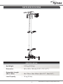
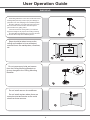
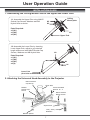
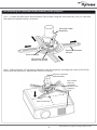
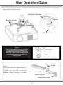
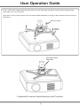
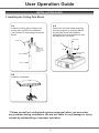
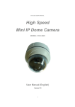
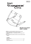
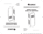
Projector
Ceiling Pole Mount
ABtUS SIGAPORE PTE
LTDOCM815W / OCM815B
Model:
Patent Pending
Optoma
www.abtussingapore.com
Revision 24/01/2014
www.optoma.com
User Operation Guide
IMPORTANT NOTES
●
Thank you for purchasing the Universal Projector Ceiling Mount. This bracket is suitable for most
projectors up to a load of 15kg (33lbs).
●
To ensure correct usage, please read this instruction manual thoroughly. Keep this manual for future
reference.
●
BRACKETS SHOULD BE MOUNTED ONLY BY A QUALIFIED INSTALLER.
●
User will be responsible for any injuries and damages that may arise from improper installation and
handing of Universal Ceiling Mounting Kit.
●
Ensure all mounting screws are appropriately positioned and properly tighten/ fastened.
●
Installers are to ensure customer’s safety during installtion.
●
We reserve the right to amend or undertake any necessary changes without prior notice.
WARNING
This symbol indicates incorrect handling. Ignoring this symbol can result in the possibility of personal
injury or even death.
CAUTION
This symbol indicates incorrect handling. Ignoring this symbol can result in the possibility of personal
injury and physical damage.
Caution
(general)
Forbidden
(general)
Required
(general)
This symbol indicates additional cautions (including warnings).
This symbol indicates forbidden actions.
This symbol indicates required actions.
2
PARTS SPECIFICATIONS
SPECIFICATION
Net Weight
: 2.52 kg (5.56 lbs)
Dimension
: 420 x 200 x 120 mm (16.5” x 7.9” x 4.7”)
Extendable Length
(Min to Max)
: Min 576mm, Max 826mm (Min 22.7”, Max 32.5” )
Load Capacity
:
15 kg (33 lbs)
3
*Specifications are subject to changes without notice.
User Operation Guide
WARNING
Assembling without the correct use of bolts and screws
at designated points may result in injury and damage to
properties or the unit collapsing from its installed position.
Should a malfuction occur disconnect the power from
the main socket and surround the area with ropes to
prevent others from getting near it.
Check and ensure the ceiling where you install can
support the weight or the projector and ceiling mounting.
All Ceiling Mounting Brackets are to be firmly secured
so the unit will not drop off its installed position.
Steps should be taken to ensure the
ceiling and installed unit can withstand
external forces like earthquakes, vibrations,
etc.
Do not remove any bolts and screws
from the Ceiling Mounting Brackets or
do any changes to the Ceiling Mounting
Brackets.
Do not install near an air-conditioner.
Do not install at place where there are
excessive dust and smoke as fire could
arise from these sources.
4
WARNING
Keep the room well ventilated to prevent
room temperature rising and possibilities
resulting in fire.
Do not install in location where room
temperature and humidity are excessively
high to prevent fire.
To prevent fire, avoid contact with water
Do not apply unnecessary stress or load
on the installed unit.
5
*Specifications are subject to changes without notice.
PACKAGE CONTENTS
1. Each package should contain the parts listed and shown below
Ceiling Mount
Plate
A
M4x15 Cross Recessed
Screw
4 pcs
B
M4x20 Cross Recessed
Screw
4 pcs
C
M4x25 Cross Recessed
Screw
4 pcs
D
M5x15 Cross Recessed
Screw
4 pcs
E
M5x20 Cross Recessed
Screw
4 pcs
F
M5x25 Cross Recessed
Screw
4 pcs
G
M6x15 Cross Recessed
Screw
4 pcs
H
M6x20 Cross Recessed
Screw
4 pcs
I
M6x25 Cross Recessed
Screw
4 pcs
1
Upper Pole
1
Lower Pole
1
1
Universal Head
Assembly
Tools Included
3mm Allen Key
1 pc
6mm Allen Key
1 pc
J
1mm Washer
4 pcs
K
2 mm Washer
4 pcs
L
4mm Washer
4 pcs
M
Bottom Spacer
4 pcs
N1
Tools Required for mount assembly
1. 1x Star / Philips Screw Driver
2. 1x 13mm Spanner
5 pcs
N2
M8 Nylock Nut
5 pcs
N3
M8 Flat Washer
10 pcs
a
M3x15 Cross Recessed
Screw
4 pcs
b
M3x20 Cross Recessed
Screw
4 pcs
c
6
M8x55 Socket Cap
Screw
M3 Flat Washer
4 pcs
d
M4x6 Cross Recessed
Screw
4 pcs
e
M5x10 Socket Button
Screw
4 pcs
f
Square Nut
4 pcs
g
Extension Bracket
(50mm)
4 pcs
User Operation Guide
INSTALLATION GUIDE
1. Assembling the Ceiling Mount Plate to the Upper and Lower Pole:
1.1 Assemble the Upper Pole using M8x55
Socket Cap Screws, Washers and M8
Nylock Nuts as shown.
Ceiling
Mount plate
N2
N3
Parts Required:
x3 (N1)
x3 (N2)
x6 (N3)
N1
Upper Pole
1.2 Assemble the Lower Pole by inserting
it onto Upper Pole, adjust to your desired
length and secure with M8x55 Socket Cap
Screws, Washers and M8 Nylock Nuts.
Parts Required:
x1 (N1)
x1 (N2)
x2 (N3)
x4 (d)
N2
d
N3
N1
Lower Pole
(Oval slits at the bottom)
2. Attaching the Universal Head Assembly to the Projector
M8x15 Socket
Cap Screw
Short Pole
M8x65
Socket Cap
Screw
Cross Recessed
Screws A— I
M5x10 Socket
Button Screw
Square Nut
1mm, 2mm, 4mm
Washers
Bottom Spacer
7
(2A) Attaching the Universal Head Assembly to the projector:
2A.1— Loosen the M5x10mm Socket Button Cap Screws using the 3mm Allen key until you can slide
the extension brackets freely, as shown.
Universal Head
Assembly
Extension Bracket
100mm
3mm Allen Key
M5x10mm Socket
Button Cap Screw
2A.2— Place projector’s Flush Mount Assembly over the projector and align the centre of the Flush
Mount with the projector’s approximate Centre of Gravity.
Centre of Universal
Head Assembly
This surface
to be approximate
parallel to the
Projector
front
Centre of Gravity
8
*Specifications are subject to changes without notice.
User Operation Guide
2A.3— Place the Bottom Spacers in between the Extension Brackets and the Projector, and align the
mounting holes as shown below.
Extension Bracket
Bottom
Spacer
Bottom Spacer
Mounting Hole
NOTE
If the mounting holes on your projector
are recessed, you may need to use
the additional spacers supplied in the
parts bag. Please select the appropriate
spacers according to the design of
your projector.
Note 2:
If you cannot align the 100mm Extension
Bracket to the mounting hole on your
projector, you may need to use the
additional 50mm Extension Brackets
shown in the diagram on the right.
M5x10mm
Screw
Extension Bracket
Square Nut
Bottom Spacer
9
User Operation Guide
2A.4— Select the correct Mounting Screws from the Parts bag and firmly screw the Universal Head
Assembly onto your Projector.
Once this is done, the Projector with Universal Head Assembly is ready to be mounted onto the Ceiling
Plate Pole.
Mounting Screw
Bottom
Spacer
Universal Head
Assembly
Completed Universal Head Assembly with Projector
10
User Operation Guide
INSTALLATION GUIDE
3. Installing the Ceiling Pole Mount
3.2
Attach the Universal Head Assembly
with the projector by inserting M8x55
Socket Cap Screw with Washers
through the slot holes and secure with
M8 Nylock Nut as shown
3.1
Install the Ceiling Mount Plate to the
ceiling with Lag Bolts and Washers
(not included in the package) as shown
below.
Lower Pole
Ceiling Plate
N2
N1
Lag Bolts and
Washers (Not
Included in the
Package)
N3
Universal Head
Assembly
Upper Pole
Lower Pole
3.3
Installtion completed.
* Please consult our authorized service personnel when you encounter
any problem during installation. We are not liable for any damage or injury
caused by mishandling or improper operation.
11
Due to continuing product development, the manufacturer reserves the right to alter specifications without notice. Published: 24.01.2014
Optoma
www.optoma.com