1
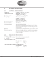
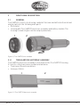
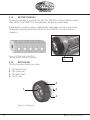
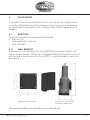
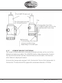
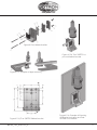
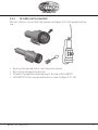
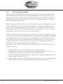
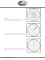
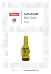
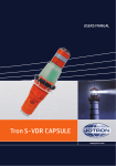
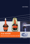
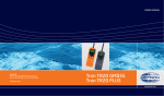
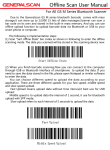
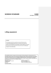
USER MANUAL
Tron SART20
www.jotron.com
www.jotron.com
2
Amendment no
By
Date
Page(s)
Vers. Reason for change
1
ES
14.09.07
Total 24
A
New product
2
ES
02.04.08
10, 15
B
Added text
3
ES
29.07.08
1
C
Background
4
ES
04.08.08
15, 16
D
Life boat bracket
updated
5
ES
14.08.08
9, 13, 21
E
Battery label
6
TH
12.02.09
10,13-19, new
tot. 28
F
Brackets and layout
7
ES
16.12.09
24
G
Added text
8
FIT
05.11.10
24-25
H
Added information
9
TH
01.02.11
15
I
New pics on figure
4.1.2b and 4.1.3
10
TH
14.04.11
Total 28
J
Updated information
11
WB
29.10.14
12
K
ms changed to us
84145_UM_SART20_K
www.jotron.com
EC Declaration of Conformity, available at www.jotron.com
ABBREVIATIONS AND DEFINITIONS
EMC
Electromagnetic Compatibility
LED
Light Emitting Diode
SART
Search and Rescue Transponder
VHF Very High Frequency
The information in this book has been carefully checked and is believed to be
accurate. However, no responsibility is assumed for inaccuracies.
CAUTION!
This equipment contains CMOS integrated circuits. Observe handling precautions to avoid static discharges which may damage these devices. Jotron AS
reserves the right to make changes without further notice to any products or
modules described herein to improve reliability, function or design. Jotron AS
does not assume any liability arising out of the application or use of the described product.
84145_UM_SART20_K
3
www.jotron.com
WARNING / IMPORTANT
Jotron AS is a prime manufacturer of safety equipment designed for rescue of
human lives and their property. For safety equipment to be effective in line with
the design parameters it is important that they are handled, stowed and maintained in compliance with the manufacturers instructions. Jotron AS cannot be
held responsible for any damage caused due to incorrect use of the equipment
or breach of laid down procedures or for failure of any specific component or
other parts of the equipment.
The chapter covering battery replacement (6.2.1) is added for information
only. Jotron AS does not take any responsibility for improper disassembling/
assembling of the beacon. We strongly recommend all service to be done by
authorized Jotron agents. In addition to normal service, Jotron agents have
the necessary equipment and knowledge to test the operational functions of
the beacon. Non-original maintenance and/or service parts may destroy the
equipment function and performance.
BATTERY SAFETY DATA SHEET
(Form: EEC directive 91/155)
(2) SAFETY ADVICE
S2
Keep out of reach of children.
S8
Keep container dry.
S26
In case of contact with eyes, rinse immediately with plenty of water
and seek medical advice.
S43
In case of fire, use D type extinguishers. Never use water.
S45
In case of accident or if you feel unwell, seek medical advice immediately (show the label where possible).
(3) FIRST AID MEASURES
In case of contact of cell contents with eyes, flush immediately with water for 15
min. With skin, wash with plenty of water and take off contaminated clothes. If
inhaled, remove from exposure, give oxygen, and seek medical advice.
(4) FIRE-FIGHTING MEASURES
Extinguishing media
4
84145_UM_SART20_K
www.jotron.com
Suitable: Type D fire extinguishers
Not to be used:
Water - CO2 - Halon, dry chemical or foam extinguishers
Special exposure hazards
Generation of chlorine, sulphur dioxide, disulphur dichloride during
thermal decomposition.
Special protective equipment
Use protective working boots, rubber apron and safety glasses with side shields.
84145_UM_SART20_K
5
www.jotron.com
TABLE OF CONTENTS
6
1
GMDSS REQUIREMENTS
1.1
GENERAL DESCRIPTION
1.2
TRON SART20 FEATURES
8
9
11
2
TECHNICAL SPECIFICATIONS
2.1
ELECTRICAL SPECIFICATIONS 2.2
MECHANICAL SPECIFICATION 12
12
12
3
FUNCTIONAL DESCRIPTION
3.1GENERAL
3.1.1
TRON SART20 ELECTRONIC ASSEMBLY
3.1.2 BATTERY MODULE
3.1.3 BOTTOM LID
13
13
13
14
14
4INSTALLATION
4.1BRACKETS
4.1.1
WALL BRACKET
4.1.2 LIFEBOAT BRACKET (OPTIONAL)
4.1.3 USING THE TELESCOPIC POLE
15
15
15
16
18
5OPERATION
5.1
ACTIVATING TRON SART20
5.1.1
DEACTIVATING TRON SART20
5.2
EXAMPLES OF USAGE IN LIFEBOAT/LIFERAFT
5.2.1 SART POCKET
5.2.2 LIFE RAFT MOUNTING STRAP
5.2.3 SART POLE MOUNTING
5.2.4 10 M REEL WITH LANYARD
5.3
TEST OF TRON SART20
19
19
19
19
20
20
20
21
22
6
24
24
24
25
27
MAINTENANCE AND TROUBLESHOOTING
6.1MAINTENANCE
6.2SERVICE
6.2.1 REPLACING THE BATTERY MODULE 6.2.2 BATTERY DISPOSAL
84145_UM_SART20_K
www.jotron.com
6.2.3INCINERATION
6.2.4 LAND FILLING
6.2.5RECYCLING
27
27
27
7
SPARE PARTS/ACCESSORIES
27
8
SERVICE AGENTS
28
84145_UM_SART20_K
7
www.jotron.com
1
GMDSS REQUIREMENTS
Jotron GMDSS products are manufactured and approved to be compliant with
relevant IMO/ SOLAS (Safety of Life at Sea) Regulations and requirements.
The SOLAS GMDSS regulations are structured such that all GMDSS ships are
required to carry a minimum set of equipment, with (basically) more equipment
being required the further the ship travels from land. GMDSS requirement for
SART (Search and Rescue Locating Device) according to SOLAS:
Chapter III, Regulation 6
2.2 Search and rescue locating devices
At least one search and rescue locating device shall be carried on each side of
every passenger ship and of every cargo ship of 500 gross tonnage and upwards. At least one search and rescue locating device shall be carried on every
cargo ship of 300 gross tonnage and upwards but less than 500 gross tonnage. Such search and rescue locating devices shall conform to the applicable
performance standards not inferior to those adopted by the Organisation*. The
search and rescue locating devices** shall be stowed in such location that they
can be rapidly placed in any survival craft other than the life raft or life rafts required by regulation 31.1.4. Alternatively one search and rescue locating device
shall be stowed in each survival craft other than those required by regulation
31.1.4. On ships carrying at least two search and rescue locating devices and
equipped with free-fall lifeboats one of the search and rescue locating devices
shall be stowed in a free-fall lifeboat and the other located in the immediate
vicinity of the navigation bridge so that it can be utilized on board and ready for
transfer to any of the other survival craft.
__________
* Refer to the Recommendation on performance standards for survival craft
radar transponders for use in search and rescue operations, adopted by the
Organization by resolution MSC.247(83) (A.802(19)), as amended) and the
Recommendation on performance standards for survival craft AIS Search and
Rescue transmitter (AIS SART), adopted by the Organization by resolution
MSC.246(83).
** One of these search and rescue locating devices may be the search and rescue locating device required by regulation IV/7.1.3.
Regulation 26 - Additional requirements for ro-ro passenger ships
2 Life rafts
2.5 Life rafts carried on ro-ro passenger ships shall be fitted with a search and
8
84145_UM_SART20_K
www.jotron.com
rescue locating device in the ratio of one search and rescue locating device for
every four life rafts. The search and rescue locating device shall be mounted inside the life raft so its antenna is more than one metre above the sea level when
the life raft is deployed, except that for canopied reversible life rafts the search
and rescue locating device shall be so arranged as to be readily accessed and
erected by survivors. Each search and rescue locating device shall be arranged
to be manually erected when the life raft is deployed. Containers of life rafts fitted with search and rescue locating devices shall be clearly marked.”
Chapter IV, Regulation 7- Radio Equipment- General
1 Every ship shall be provided with:
.3 A search and rescue locating device capable of operating either in the 9
GHz band or on
frequencies dedicated for AIS, which:
.3.1 shall be so stowed that it can be easily utilized; and
.3.2 may be one of those required by reg. III/6.2.2 for a survival craft
Tron SART20 is also compliant with relevant sections in these regulations/requirements:
• SOLAS 74 as amended, Regulation III/6.2.2, IV/7.1.3, IMO Res. MSC.97 (73)
14.7.1.3, MSC.247(83), IMO Res. A.530 (13), IMO Res. A.802 (19), IMO Res.
A.694 (17), ITU-R M.628-3 (11/93), IEC 61097-1:1992, IEC 61097-1(2007),
IEC 60945:1996 and IEC 60945 ed.4:2002
• IMO Resolutions MSC.256(84)
• COMSAR/Circ.32
• European Directive 2009/26/EC
• Other national certifications/requirements
1.1
GENERAL DESCRIPTION
Tron SART20 is emergency equipment consisting of:
• Tron SART20 radar transponder.
• Mounting rope for life rafts / life boats.
The 9 GHz radar transponder type Tron SART20 is developed by Jotron AS to
meet the rules and regulations for use on vessels and life rafts in the maritime
service. Tron SART20 meets the specifications for 9 GHz radar transponders for
use in search and rescue operations at sea.
The operating range of the Tron SART20 is up to 30 nautical miles, depend84145_UM_SART20_K
9
www.jotron.com
ing on the height of the electronic unit and the radar height of the search and
rescue unit (sea or airborne). With a radar height of 20m and the Tron SART20
placed at 1m above sea level, the range will be up to 10 nautical miles. Tron
SART20 is buoyant, however to obtain maximum performance the transponder
should be placed in a vertical position and as high up as possible in order to
achieve maximum coverage. Several mounting brackets and mounting aids are
available to ensure correct mounting and use of the radar transponder.
The purpose of the Tron SART20 is to perform a secondary alarm when search
and rescue units are searching for a life raft / lifeboat in distress. The Tron
SART20 will help the units to pinpoint exactly where the distressed boat is located in a larger area. This is done with the help of the radar on the searching
ship or helicopter.
When the Tron SART20 is interrogated (hit) by a radar signal, it will immediately
start to transmit a number of sweeps covering the complete maritime 3 cm
radar band. These sweeps are detected on the radar screen and are used to
navigate directly towards the distressed life raft, for details on radar display see
chapter 5.3. Maximum distance to a ship will normally be about 10 nm and approximately 30nm to a helicopter, dependent on the helicopters altitude. The
transponder will not give any alarms further away than this.
The primary alarm will usually be an Emergency Position Indicating Radio Beacon (EPIRB) or distress call on VHF / HF - manual or via digital selcall.
The Tron SART20 should be activated immediately after activation of the EPIRB
or by instruction from the rescue control centre. The batteries of the Tron
SART20 will last at least 96 hours in standby after activation and then minimum
8 hours of continuous operation.
Although the transponder does not send any alarm via satellite, VHF or other
radio communication, the use should be limited to short tests and emergency
situations. This is to save battery capacity in case of a situation where the transponder is needed.
1.2
TRON SART20 FEATURES
Watertight:
Tron SART20 is watertight to a depth of minimum 1 meter.
Buoyant:
10
84145_UM_SART20_K
www.jotron.com
Tron SART20 is buoyant in case the transponder is accidentally dropped into
the water. To increase coverage the SART20 should always be held or mounted
as high as possible.
Rugged design:
The Tron SART20 will withstand a drop from 20 meters into the water. It is resistant to seawater, oil and sunlight.
Handling:
Tron SART20 is designed for easy operation, with a brief operating instruction
printed on the unit. It comes standard with a 10 meter rope and a shackle hook
to be used for hanging the SART20 on the inside of a life raft.
Indicators:
Tron SART20 is equipped with an LED and a built in buzzer to indicate operation.
The LED will normally give a flash each 4 seconds to show that the Tron SART20
is activated.
When a search and rescue unit is approaching the buzzer will sound each time
the SART20 is hit by the radar. A continuous sound from the buzzer means that
the ship or helicopter is close to the Tron SART20 and the radar is hitting the
Tron SART20 continuously.
Battery unit
The battery module is to be replaced every 5.year. A battery expiry label on the
Tron SART20 housing displays the expiry date. A new battery comes complete
with cable and connector.
84145_UM_SART20_K
11
www.jotron.com
2
TECHNICAL SPECIFICATIONS
2.1
ELECTRICAL SPECIFICATIONS
Frequency: X-band (3 cm) (9.2 - 9.5 GHz)
Temperature range: Operating: -20 to +55°C
Storage: -30 to +65°C
Radiated power:
> 400 mW e.i.r.p (+26 dBm)
Sweep type: 12 sweep sawtooth type
Forward 7.5 us ±1 us
Return 0.4 us ±0.1 us
Starts with return sweep
Receive sensitivity: Better than -50 dBm e.r.s.
Response delay:
Max 0.5 us
Antenna pattern:
Horizontal polarization
Omni directional radiation in the horizontal plane.
Greater than ±12.5 degrees elevation angle in the
vertical plane
Battery: Lithium metal 7,2V/3600 mAh, 5 years service life.
Battery capacity: 96 hours standby +8 hours continuous operation
when activated by a radar with 1 kHz prf at -20°C.
5 years storage
2.2
MECHANICAL SPECIFICATION
Materials used:
• Transponder housing: Glass reinforced polycarbonate
• Bracket: Anodized aluminum
Transponder dimensions:
Max diameter: 89 mm
Length:
250 mm
Weight:
482 g
Transponder with standard storage bracket:
Max diameter: 90 mm
Length: 250 mm
12
84145_UM_SART20_K
www.jotron.com
3
FUNCTIONAL DESCRIPTION
3.1
GENERAL
Tron SART20 consists of a housing sealed at the lower end with a bottom lid and
may be split into the following main parts:
• Bottom lid
• Housing with Tron SART20 electronic assembly and battery module. The
housing is made of glass reinforced polycarbonate
1
2
Figure 3.1, Tron SART20 disassembled
3.1.1
TRON SART20 ELECTRONIC ASSEMBLY
Tron SART20 electronic assembly is inserted into the Tron SART20 housing.
It consists of the transceiver module and antenna.
• Transceiver Board in metal box
• Antenna (9GHz).
1
2
Figure 3.1.1 Tron SART20 electronic assembly
84145_UM_SART20_K
13
www.jotron.com
3.1.2
BATTERY MODULE
The battery module is inserted into the Tron SART20 housing. A battery expiry
label on the Tron SART20 housing displays the battery expiry date.
A new battery module comes complete with cable and connector and can be
changed by opening the bottom lid of the Tron SART20, see description in
chapter 6
Figure 3.1.2 TRON SART20 BATTERY
- module without cable and connector
Battery expiry
label
3.1.3
BOTTOM LID
The Bottom lid includes four items:
1.
2.
3.
4.
The winder hook
The screw ring
The light tower
The O-ring
2
1
3
4
14
Figure 3.1.3 Bottom lid
84145_UM_SART20_K
www.jotron.com
4
INSTALLATION
Tron SART20 can be mounted several ways; near the vessels emergency exit,
normally in the wheelhouse at the starboard or port exit (or both, depending
of requirements) and inside life raft or lifeboat. (See”GMDSS requirements in
chapter 1.
4.1
BRACKETS
There are 3 different mounting brackets available.
• Wall bracket
• Lifeboat bracket (optional)
• Pole (optional)
4.1.1
WALL BRACKET
A wall bracket is delivered with the Tron SART20 and should be used for storage of the transponder. The bracket should preferably be mounted in a vertical
position and in a place where the Tron SART20 is easily available in case of an
emergency.
Figure 4.1.1a, wall bracket.
Figure 4.1.1b, Tron SART20 mounted in wall bracket.
The bracket should be mounted with four screws (Ø 4 mm).
84145_UM_SART20_K
15
www.jotron.com
Tron SART20 main unit
The state when inserted
into the wall bracket
Clip
Insert the clip of the
SART20 main unit into the
wall bracket from a top
Wall
Wall bracket:
- For mounting, use 4 mm screws or wood screws, depending on the wall type
4.1.2
LIFEBOAT BRACKET (OPTIONAL)
The outdoor lifeboat bracket should be mounted vertically on the roof of the
lifeboat (as high as possible). Tron SART20 shall not be permanently stored in
this bracket if mounted outside a freefall lifeboat, but moved to this bracket
after lifeboat is deployed in water.
Activate the transponder and put it into the bracket. Secure the transponder to
the bracket. The bracket will fit a pipe with a maximum diameter of 50mm.
16
84145_UM_SART20_K
www.jotron.com
Figure 4.1.2a, Lifeboat bracket
Figure 4.1.2b, Tron SART20 to
put into lifeboat bracket
Figure 4.1.2c, Examples of pipe mounting
6,3
5,3
Figure 4.1.2d, Tron SART20 lifeboat bracket
84145_UM_SART20_K
Figure 4.1.2e Example of Mounting
the Bracket on Interior and Exterior Walls of a Lifeboat
17
www.jotron.com
4.1.3
USING THE TELESCOPIC POLE
Figure 4.1.3 Tron SART20 with telescopic pole attached.
A telescopic pole can be used to extend the height of the Tron SART20, inside
or outside the life raft/boat. Simply extend the attached pole to the full length
(app. 1,2m from the top of the Tron SART20). Make sure that the rod is locked
by pulling hard when it is fully extended. The rod can now be fastened or held by
a person. Ensure the rod is held as vertical as possible when activating the Tron
SART20.
May be used for mounting inside a life raft (optional).
18
84145_UM_SART20_K
www.jotron.com
5
OPERATION
Tron SART20 should be installed according to chapter 1 and 4, and in a distress
situation, the Tron SART20 should be carried from its storage position to the life
raft/lifeboat
5.1
ACTIVATING TRON SART20
• Break seal at switch.
• Pull locking pin and make sure that the switch enters the “ON” position. An
audible “BEEP” will be heard and the indicator led will start to flash every 4 sec
• Place (or hold) the transponder in a vertical position as high as possible.
When the Tron SART20 is within range of an active 3 cm radar x-band, the
internal loudspeaker will be activated. A handheld VHF radio should now be
used to establish contact with the approaching boat or helicopter.
After activating the Tron SART20, it shall be mounted in lifeboat/life raft as described in ch. 5.3.
5.1.1
DEACTIVATING TRON SART20
• Move the switch to the “OFF” position.
• Replace the locking pin.
5.2
EXAMPLES OF USAGE IN LIFEBOAT/LIFERAFT
Figure 5.2.1, How to mount Tron SART20 to a life raft
84145_UM_SART20_K
19
www.jotron.com
From figure 5.2.1 above, left to right:
• Using ”life raft mounting strap” (or optionally the 10m lanyard)
• SART pocket
• Pole
5.2.1
SART POCKET
There are different ways of mounting a Tron SART20 in an inflatable Life Raft:
It is often a SART pocket where the Tron SART20 may be lifted to the canopy
after deploying the raft (See figure 5.2.1, middle)
• Put the SART20 into the SART pocket.
• Lift the pocket by its rope to the canopy
5.2.2
LIFE RAFT MOUNTING STRAP
We can supply a”SART Life-raft mounting strap” (part no. 85120) as seen on
the attached pictures to be mounted to the inflatable canopy.
• Attach the strap as seen on picture above
• Fasten the other end to the canopy as seen on figure 5.2.1
5.2.3
SART POLE MOUNTING
You may use the 1m Pole arrangement (part no. 82900) (See figure 5.2.1, right)
• Attach the pole to SART20
• Extend the pole to its full length and make sure it is ”locked”
• Lift it up through the tent air tube (if available) and secure using the life rafts
mounting for SART pole (strap, rope etc.)
20
84145_UM_SART20_K
www.jotron.com
5.2.4
10 M REEL WITH LANYARD
The last solution is to use the 10m lanyard (see figure 5.2.1, left) and picture below.
•
•
•
•
Remove the lanyard reel as seen on picture above
Roll out the lanyard from the reel
Thread it through the fastening ring of the top of the SART20
Lift SART20 to the canopy and fasten as seen on figure 5.2.1, left
84145_UM_SART20_K
21
www.jotron.com
5.3
TEST OF TRON SART20
Test of the Tron SART20 is done using the ships own 3 cm X-band radar. The
radar display will show different patterns depending on the range to the transponder. See Figure 5.3a, b and c for details of the radar display. Note that the
examples shown are typical and will vary with the radar performance (height,
power output and sensitivity).
With the transponder located close to the radar the signals will appear as rings
on the radar display. The rings may be broken in some sectors, depending on
ship construction and other obstacles, and does not indicate an error in the
transponder. Placing it further away will reduce the signals to 12 dots on the radar display, showing the direction to the transponder.
Modern radars often have special function that will optimize reception of radar
SART, either in TEST or ON. If the Radar has such function, the Radar is detuned
out of best tuning condition, and erases or weakens all normal radar echoes,
but SART echoes are not erased because SART frequencies scans over all the
X-band from 9.2 to 9.5 GHz. When this function is selected on the radar, a
text”SART” is shown at the bottom of the display.
Note! Make sure that the SART feature is turned off when SART detection is no
longer necessary
• Hold the switch on the Tron SART20 in the “TEST” position.
• Simultaneously a person should observe the radar display to check for correct pattern. The radar should be set for a 10 nm range.
• The test should preferably be done in open sea to avoid interference on the
radar display from land echoes.
• Alternatively, a radar of a nearby ship can be used to test the transponder. A
ship to ship VHF channel should then be used to confirm operation.
22
84145_UM_SART20_K
www.jotron.com
Figure 5.3a
Typical display when Tron SART20 is located near (<0.2 nm)
the radar. Radar range is 10 nm. Rings are off.
Figure 5.3.b Typical display when Tron SART20 is located
close (1nm) to the radar. Radar range is 10 nm. Rings are at
2 nm.
Figure 5.3c Typical display when Tron SART20 is located
away (>2 nm) from the radar. Radar range is 10 nm. Rings are
at 2 nm.
84145_UM_SART20_K
23
www.jotron.com
CAUTION!
While the Tron SART20 is activated it will respond to any 3 cm radars
within range. Tests must be made as short as possible (5 min) to avoid interference and to avoid wasting battery capacity.
6
MAINTENANCE AND TROUBLESHOOTING
6.1
MAINTENANCE
Tron SART20 requires the following maintenance:
At least every 6. month.
The transponder should be taken out of its bracket and tested against a radar,
using the procedure in chapter 5.3. Either the ships own radar could be used or
the radar of a nearby ship. Note that the self test use the internal battery and
will reduce the operational lifetime of the equipment - therefore the test should
be limited to not more than once every month.
Every 5. year.
The battery unit must be replaced every 5 year. Storage of batteries over a long
period of time will reduce their capacity. To ensure long and reliable operation
the battery unit must be replaced every 5 year. The battery replacement can be
performed on board using the procedure in chapter 6.2.1.
6.2
SERVICE
Warranty Service
All goods sold by the Company are warranted to be free from defect in workmanship and material for the period of five (5) years from the date of purchase
from Jotron. For further information, see pos.6 “Guarantee” in our Terms and
Conditions of Sale.
Provided that the unit(s) returned for repair is under warranty, man-hour cost
and material cost will be covered by Jotron. This is not valid if the customer
has tried to repair, modify or rebuild the unit, or if the unit has been exposed to
environmental conditions outside the specifications for the unit. If the unit is in
need of repair, please return it carriage paid to the agent that you purchased it
from. Additional costs not related to repair/replacement of the unit will not be
covered.
24
84145_UM_SART20_K
www.jotron.com
Out of Warranty Service
For defects arising from normal wear and tear after 12 months of operation,
limited to 18 months from Jotron AS, normal service conditions will apply. For
details see: www.jotron.com
6.2.1
6.2.1 REPLACING THE BATTERY MODULE
Below is a description on how to change batteries on AIS-SART
6.2.1.1
DISSASSEMBLY
Twist the rubber grip
anti-clockwise to
remove the lid
It might be difficult
to remove the lid. If
so, remove the rubber grip first
And then twist off
the lid
Rubber holder below
battery and electronics removed
Pull out the battery
Pull out the cable from connector
Remove old Silaca
gel bags
84145_UM_SART20_K
Opened
See these pictures in colours on www.jotron.com
25
www.jotron.com
6.2.1.2
ASSEMBLY
Install the new battery. Make sure the
cable is within the
guide
Connect cable to
electronics,
black= left,
red= right
Add 2x5 g Silica
gel bags
Mount rubber
holder
Remove old O-ring
using a Credit Card
Use acid-free
Vaseline on the
new O-ring
Fit the new
O-ring
Reinstall lid- tighten without tools
Replace the rubber grip
Assembly completed
See these pictures in colours on www.jotron.com
26
84145_UM_SART20_K
www.jotron.com
6.2.2
BATTERY DISPOSAL
Dispose in accordance with applicable regulations, which vary from country
to country.(In most countries, the disposal of used batteries is regulated and
end-users are invited to dispose of them correctly, through non-profit organizations, mandated by local governments or organized on a voluntary basis by
professionals).Lithium batteries should have their terminals insulated prior to
disposal.
6.2.3
INCINERATION
Incineration should never be performed by battery users but by trained professionals in authorized facilities with proper gas and fumes treatment.
6.2.4
6.2.4 LAND FILLING
Leachability regulations (mg/l)
Component
Lachability
EC limit
EPA
Other*
Iron
Nickel
100
100
500
2
5
0,5
6.2.5
RECYCLING
Send to authorized recycling facilities, through a licensed waste carrier.
7
SPARE PARTS/ACCESSORIES
83010
84065
82900
82120
82615
82746 Tron SART20 Main unit
Lifeboat bracket
Pole bracket
Life raft mounting strap
Battery, Tron SART20, 5 years maintenance kit
Bulkhead bracket
84145_UM_SART20_K
27
www.jotron.com
8
SERVICE AGENTS
Please look at www.jotron.com for Marine Service Agents.
Jotron Group subsidiary companies:
Jotron UK Ltd.
Crosland Park
Cramlington
NE23 1LA
United Kingdom
Tel
+44 1670 712000
Fax
+44 1670 590265
E-mail: [email protected]
Jotron Asia Pte. Ltd.
Changi Logistics Center
19 Loyang Way #04-26
Singapore 508724
Tel
+65 65426350
Fax
+65 65429415
E-mail: [email protected]
Jotron USA, Inc.
10645 Richmond Avenue, Suite 170
Houston, TX 77042
USA
Tel
+1 713 268 1061
Fax
+1 713 268 1062
E-mail: [email protected]
28
84145_UM_SART20_K
www.jotron.com
84145_UM_SART20_K
29
CONTACT INFORMATION
Jotron AS
Jotron AS
Jotron UK Ltd.
Jotron Asia Pte. Ltd.
P.O.Box 54
3281 Tjodalyng
Norway
Tel: +47 33 13 97 00
Fax: +47 33 12 67 80
[email protected]
Crosland Park
Cramlington
NE23 1LA
United Kingdom
Tel: +44 (0) 1670 712000
Fax: +44 (0) 1670 590265
[email protected]
P.O.Box 23
3195 Skoppum
Norway
Tel: +47 33 13 97 00
Fax: +47 33 12 67 80
[email protected]
19 Loyang Way
Changi Logistics Centre
Rear Office Block 04-26
Singapore 508724
Tel: +65 65426350
Fax: +65 65429415
[email protected]
Jotron USA, Inc.
10645 Richmond Avenue
Suite 170
Houston, TX 77042
USA
Tel: +1 713 268 1061
Fax: +1 713 268 1062
[email protected]