1
20PX01-00 E2 – 2014-06-13
User Manual
PX1 – GLONASS & GPS
PCI Express® Mini Card
Configuration example
PX1 - GLONASS & GPS PCI Express® Mini Card
PX1 - GLONASS & GPS PCI Express® Mini Card
The PX1 is a PCI Express® Mini Card providing a GNSS receiver with GLONASS
and GPS functionality. It supports active or passive antennas, which can be
connected to an U.FL connector. The received antenna signals are sent to the host
via USB.
GLONASS is the Russian alternative to GPS and has comparable coverage and
precision. The PX1 is prepared to support the European Union's global navigation
satellite system Galileo and the Chinese navigation satellite system Compass.
The GNSS module provides a gyroscope sensor for dead reckoning functions,
which enable accurate positioning. Various Satellite-Based Augmentation Systems
(SBAS) are also supported. The PX1 provides communication information
compliant to the NMEA 0183 protocol.
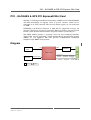
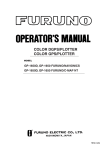
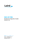
Diagram
UART
I2C
Gyroscope sensor
USB2UART
USB
PCIe Mini Card
GNSS receiver
Odometer
U. FL antenna Antenna signal
connector
B Onboard
MEN Mikro Elektronik GmbH
20PX01-00 E2 – 2014-06-13
PPS
B
Options
2
Technical Data
Technical Data
GNSS Interface
•
•
•
•
•
•
•
•
•
•
•
•
•
•
•
32-channel GNSS (Global Navigation Satellite System) receiver
GPS Band/Code: L1 frequency, C/A code, SPS
GLONASS Band/Code: L1 frequency, C/A code, SP
Integrated TCXO, RTC
Assisted GPS support
Dead Reckoning support (gyroscope)
Differential GPS support
- Satellite Based Augmentation System (WAAS, Egnos, MSAS)
- RTCM104
Accuracy (unaided):
- Position: 3 m horizontal, 5 m vertical
- Velocity: 0.05 m/s
- Time: 1 μs
Time To First Fix (TTFF):
- Cold start: 35 s typ.
- Hot start: 2 s typ.
Sensitivity:
- Acquisition (cold): -147 dBm
- Re-Acquisition: -157 dBm
- Tracking: -161 dBm
Acceleration: 5 g max.
Velocity: 515 m/s max.
Altitude: 18 000 m max.
Protocol: NMEA 0183 rev. 3.01
One U.FL antenna connector
- For the use of an external active or passive antenna
- Phantom power supply: 3.3V
Host Interface
• PCI Express® Mini Card connector
- USB 2.0
Electrical Specifications
• Supply voltage/power consumption:
- +3.3 V, max. 191 mA
- Impedance: 50 Ohm
Mechanical Specifications
• Dimensions: 30 mm x 58 mm x 5 mm (PCI Express® Full-Mini Card)
• Weight: 4 g
MEN Mikro Elektronik GmbH
20PX01-00 E2 – 2014-06-13
3
Technical Data
Environmental Specifications
• Temperature range (operation):
- -40..+85°C (qualified)
- Airflow: min. 1 m/s
• Temperature range (storage): -40..+85°C
• Relative humidity (operation): max. 95% non-condensing
• Relative humidity (storage): max. 95% non-condensing
• Altitude: -300 m to +3000 m
• Shock: 15 g, 11 ms
• Bump: 10 g, 16 ms
• Vibration (sinusoidal): 1 g, 10..150 Hz
• Conformal coating on request
MTBF
• tbd h @ 40°C according to IEC/TR 62380 (RDF 2000)
Safety
• PCB manufactured with a flammability rating of 94V-0 by UL recognized
manufacturers
EMC Conformity
•
•
•
•
•
•
EN 50121-3-2 (table 4) (EMC in rolling stock)
EN 55011 (radio disturbance)
EN 61000-4-2/EN 50121-3-2 (table 9) (ESD)
EN 61000-4-3/EN 50121-3-2 (table 9) (electromagnetic field immunity)
EN 61000-4-4/EN 50121-3-2 (table 8) (burst)
EN 61000-4-6/EN 50121-3-2 (table 7) (immunity to conducted disturbances)
Software Support
• For information on first installation please contact MEN.
Also see Configuration Options.
MEN Mikro Elektronik GmbH
20PX01-00 E2 – 2014-06-13
4
Configuration Options
Configuration Options
Functionality
• Odometer input/PPS output
• Without Dead Reckoning support (gyroscope not assembled)
• Phantom power supply: 3.3V
Mechanical
• Conformal coating
Please note that some of these options may only be available for large volumes.
Please ask our sales staff for more information.
For available standard configurations see the online data sheet.
MEN Mikro Elektronik GmbH
20PX01-00 E2 – 2014-06-13
5
Product Safety
Product Safety
Electrostatic Discharge (ESD)
!
MEN Mikro Elektronik GmbH
20PX01-00 E2 – 2014-06-13
Computer boards and components contain electrostatic sensitive
devices. Electrostatic discharge (ESD) can damage components. To
protect the board and other components against damage from static
electricity, you should follow some precautions whenever you work on
your computer.
• Power down and unplug your computer system when working on the
inside.
• Hold components by the edges and try not to touch the IC chips,
leads, or circuitry.
• Use a grounded wrist strap before handling computer components.
• Place components on a grounded antistatic pad or on the bag that
came with the component whenever the components are separated
from the system.
• Only store the board in its original ESD-protected packaging. Retain
the original packaging in case you need to return the board to MEN
for repair.
6
About this Document
About this Document
This user manual is intended only for system developers and integrators, it is not
intended for end users.
It describes the hardware functions of the board, connection of peripheral devices
and integration into a system. It also provides additional information for special
applications and configurations of the board.
The manual does not include detailed information on individual components (data
sheets etc.). A list of literature is given in the appendix.
History
Issue
Date
E1
First issue
2013-05-06
E2
Added: Phantom power supply: 3.3V
2014-06-13
MEN Mikro Elektronik GmbH
20PX01-00 E2 – 2014-06-13
Comments
7
About this Document
Conventions
Indicates important information or warnings concerning the use of
voltages that could lead to a hazardous situation which could result in
personal injury, or damage or destruction of the component.
!
Indicates important information or warnings concerning proper
functionality of the product described in this document.
The globe icon indicates a hyperlink that links directly to the Internet,
where the latest updated information is available.
When no globe icon is present, the hyperlink links to specific elements
and information within this document.
italics
Folder, file and function names are printed in italics.
bold
Bold type is used for emphasis.
mono
A monospaced font type is used for hexadecimal numbers, listings, C
function descriptions or wherever appropriate. Hexadecimal numbers
are preceded by "0x".
comment
Comments embedded into coding examples are shown in green text.
IRQ#
/IRQ
Signal names followed by a hashtag "#" or preceded by a forward
slash "/" indicate that this signal is either active low or that it becomes
active at a falling edge.
in/out
Signal directions in signal mnemonics tables generally refer to the
corresponding board or component, "in" meaning "to the board or
component", "out" meaning "from it the board or component".
Blue vertical lines in the outer margin indicate sections where changes
have been made to this version of the document.
MEN Mikro Elektronik GmbH
20PX01-00 E2 – 2014-06-13
8
About this Document
Legal Information
Changes
MEN Mikro Elektronik GmbH ("MEN") reserves the right to make changes without further notice to any products
herein.
Warranty, Guarantee, Liability
MEN makes no warranty, representation or guarantee of any kind regarding the suitability of its products for any
particular purpose, nor does MEN assume any liability arising out of the application or use of any product or
circuit, and specifically disclaims any and all liability, including, without limitation, consequential or incidental
damages. TO THE EXTENT APPLICABLE, SPECIFICALLY EXCLUDED ARE ANY IMPLIED
WARRANTIES ARISING BY OPERATION OF LAW, CUSTOM OR USAGE, INCLUDING WITHOUT
LIMITATION, THE IMPLIED WARRANTIES OF MERCHANTABILITY AND FITNESS FOR A
PARTICULAR PURPOSE OR USE. In no event shall MEN be liable for more than the contract price for the
products in question. If buyer does not notify MEN in writing within the foregoing warranty period, MEN shall
have no liability or obligation to buyer hereunder.
The publication is provided on the terms and understanding that:
1. MEN is not responsible for the results of any actions taken on the basis of information in the publication, nor
for any error in or omission from the publication; and
2. MEN is not engaged in rendering technical or other advice or services.
MEN expressly disclaims all and any liability and responsibility to any person, whether a reader of the publication
or not, in respect of anything, and of the consequences of anything, done or omitted to be done by any such person
in reliance, whether wholly or partially, on the whole or any part of the contents of the publication.
Conditions for Use, Field of Application
The correct function of MEN products in mission-critical and life-critical applications is limited to the
environmental specification given for each product in the technical user manual. The correct function of MEN
products under extended environmental conditions is limited to the individual requirement specification and
subsequent validation documents for each product for the applicable use case and has to be agreed upon in writing
by MEN and the customer. Should the customer purchase or use MEN products for any unintended or
unauthorized application, the customer shall indemnify and hold MEN and its officers, employees, subsidiaries,
affiliates, and distributors harmless against all claims, costs, damages, and expenses, and reasonable attorney fees
arising out of, directly or indirectly, any claim or personal injury or death associated with such unintended or
unauthorized use, even if such claim alleges that MEN was negligent regarding the design or manufacture of the
part. In no case is MEN liable for the correct function of the technical installation where MEN products are a part
of.
Trademarks
All products or services mentioned in this publication are identified by the trademarks, service marks, or product
names as designated by the companies which market those products. The trademarks and registered trademarks
are held by the companies producing them. Inquiries concerning such trademarks should be made directly to those
companies.
Conformity
MEN products are no ready-made products for end users. They are tested according to the standards given in the
Technical Data and thus enable you to achieve certification of the product according to the standards applicable in
your field of application.
MEN Mikro Elektronik GmbH
20PX01-00 E2 – 2014-06-13
9
About this Document
RoHS
Since July 1, 2006 all MEN standard products comply with RoHS legislation.
Since January 2005 the SMD and manual soldering processes at MEN have already been completely lead-free.
Between June 2004 and June 30, 2006 MEN’s selected component suppliers have changed delivery to RoHScompliant parts. During this period any change and status was traceable through the MEN ERP system and the
boards gradually became RoHS-compliant.
WEEE Application
The WEEE directive does not apply to fixed industrial plants and tools. The compliance is the responsibility of the
company which puts the product on the market, as defined in the directive; components and sub-assemblies are
not subject to product compliance.
In other words: Since MEN does not deliver ready-made products to end users, the WEEE directive is not
applicable for MEN. Users are nevertheless recommended to properly recycle all electronic boards which have
passed their life cycle.
Nevertheless, MEN is registered as a manufacturer in Germany. The registration number can be provided on
request.
Copyright © 2014 MEN Mikro Elektronik GmbH. All rights reserved.
Germany
MEN Mikro Elektronik GmbH
Neuwieder Straße 3-7
90411 Nuremberg
Phone +49-911-99 33 5-0
Fax +49-911-99 33 5-901
E-mail [email protected]
www.men.de
MEN Mikro Elektronik GmbH
20PX01-00 E2 – 2014-06-13
France
MEN Mikro Elektronik SAS
18, rue René Cassin
ZA de la Châtelaine
74240 Gaillard
Phone +33 (0) 450-955-312
Fax +33 (0) 450-955-211
E-mail [email protected]
www.men-france.fr
USA
MEN Micro Inc.
860 Penllyn Blue Bell Pike
Blue Bell, PA 19422
Phone (215) 542-9575
Fax (215) 542-9577
E-mail [email protected]
www.menmicro.com
10
Contents
Contents
1 Getting Started . . . . . . . . . . . . . . . . . . . . . . . . . . . . . . . . . . . . . . . . . . . . . . . . 12
1.1 Map of the Board. . . . . . . . . . . . . . . . . . . . . . . . . . . . . . . . . . . . . . . . . 12
1.2 Integrating the Board into a System . . . . . . . . . . . . . . . . . . . . . . . . . . 12
2 Connecting the PCI Express Mini Card . . . . . . . . . . . . . . . . . . . . . . . . . . . . 13
2.1 Peripheral Interface . . . . . . . . . . . . . . . . . . . . . . . . . . . . . . . . . . . . . . . 13
2.2 Host Interface . . . . . . . . . . . . . . . . . . . . . . . . . . . . . . . . . . . . . . . . . . . 13
3 Functional Description . . . . . . . . . . . . . . . . . . . . . . . . . . . . . . . . . . . . . . . . . .
3.1 Power Supply. . . . . . . . . . . . . . . . . . . . . . . . . . . . . . . . . . . . . . . . . . . .
3.1.1
Power Supply for Active Antennas . . . . . . . . . . . . . . . . . . . .
3.2 GNSS Interface . . . . . . . . . . . . . . . . . . . . . . . . . . . . . . . . . . . . . . . . . .
3.3 Software Requirements . . . . . . . . . . . . . . . . . . . . . . . . . . . . . . . . . . . .
15
15
15
15
15
4 Appendix . . . . . . . . . . . . . . . . . . . . . . . . . . . . . . . . . . . . . . . . . . . . . . . . . . . . .
4.1 Literature and Web Resources . . . . . . . . . . . . . . . . . . . . . . . . . . . . . . .
4.1.1
PCI Express Mini Card . . . . . . . . . . . . . . . . . . . . . . . . . . . . .
4.1.2
GNSS . . . . . . . . . . . . . . . . . . . . . . . . . . . . . . . . . . . . . . . . . .
4.2 Finding out the Product’s Article Number, Revision
and Serial Number . . . . . . . . . . . . . . . . . . . . . . . . . . . . . . . . . . . . . . . .
16
16
16
16
16
Figures
Figure 1. Map of the board – top view. . . . . . . . . . . . . . . . . . . . . . . . . . . . . . . . . 12
Figure 2. Labels showing the product’s article number, revision
and serial number . . . . . . . . . . . . . . . . . . . . . . . . . . . . . . . . . . . . . . . . . 16
Tables
Table 1.
Table 2.
Pin assignment of PCI Express Mini Card connector . . . . . . . . . . . . . 13
Signal mnemonics of 52-pin PCI Express Mini Card connector . . . . . 14
MEN Mikro Elektronik GmbH
11
20PX01-00 E2 – 2014-06-13
Getting Started
1
Getting Started
This chapter gives an overview of the board and some hints for first installation in a
system.
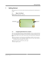
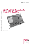
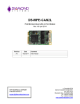
1.1
Map of the Board
Figure 1. Map of the board – top view
1
PCI Express Mini Card connector
1.2
U.FL antenna connector
Integrating the Board into a System
You can use the following check list when installing the card in a system for the first
time and with minimum configuration. The installation of the PX1 depends on the
carrier board. Please refer to your carrier board’s user manual before installing the
PX1.
Power down the system and remove the PCI Express Mini Card carrier board.
Install the PX1 on the PCI Express Mini Card slot of the carrier board as
described in the carrier board’s user manual.
Insert the carrier board into the system again
Power up the system.
MEN Mikro Elektronik GmbH
20PX01-00 E2 – 2014-06-13
12
Connecting the PCI Express Mini Card
2
Connecting the PCI Express Mini Card
2.1
Peripheral Interface
An external active or passive antenna can be connected to the U.FL antenna
connector. Depending on the used antenna, an U.FL to SMA adapter might be
required to connect an antenna.
2.2
Host Interface
The PX1 connects to the carrier board via a PCI Express Mini Card connector.
PCI Express® Mini Cards use either a single PCI Express lane (x1) or a USB
connection; the PX1 only supports the USB 2.0 connection. It is equipped with one
52-pin standard PCI Express Mini Card connector. The following standard signals
are supported (signal directions according to PCI Express Mini Card standard):
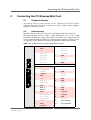
Table 1. Pin assignment of PCI Express Mini Card connector
2
52
MEN Mikro Elektronik GmbH
20PX01-00 E2 – 2014-06-13
1
51
2
+3.3Vaux
1
WAKE#
4
GND
3
reserved
6
1.5V
5
reserved
8
UIM_PWR
7
CLKREQ#
10
UIM_DATA
9
GND
12
UIM_CLK
11
REFCLK-
14
UIM_RST
13
REFCLK+
16
UIM_VPP
15
GND
18
GND
17
reserved
20
W_DISABLE#
19
reserved
22
PERST#
21
GND
24
+3.3Vaux
23
PERn0
26
GND
25
PERp0
28
+1.5V
27
GND
30
SMB_CLK
29
GND
32
SMB_DATA
31
PETn0
34
GND
33
PETp0
36
USB_D-
35
GND
38
USB_D+
37
GND
40
GND
39
+3.3Vaux
42
LED_WWAN#
41
+3.3Vaux
44
LED_WLAN#
43
GND
46
LED_WPAN#
45
reserved
48
+1.5V
47
reserved/ODO
50
GND
49
reserved/1PPS
52
+3.3Vaux
51
reserved
13
Connecting the PCI Express Mini Card
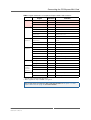
Table 2. Signal mnemonics of 52-pin PCI Express Mini Card connector
Signal
Power
Function
GND
-
Ground
+3.3Vaux
out
3.3V source
1.5V
out
1.5V source
UIM_PWR
in
SIM card power
UIM_DATA
in/out
SIM card data
UIM_CLK
in
SIM card clock
UIM_RST
in
SIM card reset
UIM_VPP
in
not connected
REFCLKREFCLK+
out
PCI Express differential reference
clock
PERn0/PERp0
in
PCI Express receive signals
PETn0/PETp0
out
PCI Express transmit signals
CLKREQ#
in
Clock request
PERST#
out
Reset for the Mini Card
W_DISABLE#
out
Wireless disable
WAKE#
in
Wake signal
SMB_CLK
out
System management bus clock
SMB_DATA
in/out
System management bus data
USB_D-
in/out
USB line
USB_D+
in/out
USB line
Communi
cations specific
signals1
LED_WWAN#
in
not connected
LED_WLAN#
in
not connected
LED_WPAN#
in
not connected
Optional 2
ODO
in
Odometer input
1PPS
out
PPS output
SIM
card1
PCI
Express1
Auxiliary
Signals1
USB
1
2
Direction
Signals in grey font are not supported.
These signals are only available as an option.
Please refer to the PCI Express Mini Card Specifications in Chapter 4.1.1 PCI
Express Mini Card on page 16, for further details
MEN Mikro Elektronik GmbH
20PX01-00 E2 – 2014-06-13
14
Functional Description
3
Functional Description
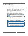
3.1
Power Supply
The PX1 is supplied with 3.3V via the PCI Express Mini Card connector.
3.1.1
Power Supply for Active Antennas
The standard power supply for the PX1 is 3.3 V. A phantom supply is available as an
option, allowing the PX1 to supply active GPS antennas with 3.3 V or 5 V. In
addition, it is possible to extend the power supply to 3.5 V or 5 V with either an
optional assembly, or a version that has been configured specifically.
3.2
GNSS Interface
The PX1 is equipped with a 32-channel Fastrax IT600 GNSS receiver, which
supports GPS and GLONASS funtionality. The GNSS signals are received via an
onboard U.FL connector, which has to be connected to an external antenna.
The PX1 itself has no antenna. Please note that MEN does not supply antennas
with the PX1, since the choice of a suitable antenna depends on your
application.
Please see Technical Data for detailed information on the GNSS interface.
3.3
Software Requirements
The PX1 does not require a specific driver. The USB2UART interface is supported
under Linux, kernels higher than 3.0 and under Windows 7 and newer.
Please check the MEN website for a VxWorks driver.
For evaluation software, please see the u-blox website (GNSS receiver
manufacturer).
For integration software please go to FreeGPS.
For more information on first installation please contact the MEN sales
team.
MEN Mikro Elektronik GmbH
20PX01-00 E2 – 2014-06-13
15
Appendix
4
Appendix
4.1
Literature and Web Resources
PX1 data sheet with up-to-date information and documentation:
www.men.de/products/15PX01-.html
4.1.1
PCI Express Mini Card
PCI Express Mini Card Electromechanical Specification Rev. 2.0
August 31, 2011
PCI Special Interest Group
www.pcisig.com
4.1.2
GNSS
• Fastrax IT600 GNSS Receiver
www.u-blox.com/images/downloads/Product_Docs/
IT600_Datasheet.pdf
• GNSS in general
en.wikipedia.org/wiki/Satellite_navigation
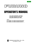
4.2
Finding out the Product’s Article Number, Revision and
Serial Number
MEN user documentation may describe several different models and/or design
revisions of the PX1. You can find information on the article number, the design
revision and the serial number on a label attached to the board.
• Article number: Gives the product’s family and model. This is also MEN’s
ordering number. To be complete it must have 9 characters.
• Revision number: Gives the design revision of the product.
• Serial number: Unique identification assigned during production.
If you need support, you should communicate these numbers to MEN.
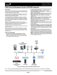
Figure 2. Labels showing the product’s article number, revision and serial number
Complete article number
15PX01-00
00.00.00
Revision number
MEN Mikro Elektronik GmbH
20PX01-00 E2 – 2014-06-13
Serial number
16