1
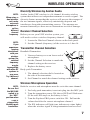
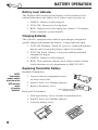
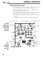
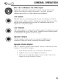
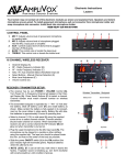
TROUBLESHOOTING GUIDE
Having trouble with the sound system?
Condition
Possible Solution
No sound (power LED not lit):
•
•
•
•
•
•
•
Charge indicator doesn’t light:
No sound (power LED lights):
Shortened battery life:
•
Distorted sound:
Excessive hum or noise:
•
•
•
turn POWER switch ON
charge battery or plug in AC cord
leave plugged in for 48 hours to repair battery
check for output from source
make sure all cables are completely plugged in
turn up volume control of input used
remove plug from speaker output if not using
external speaker output
charge battery fully; if battery life continues to
deteriorate, contact Anchor customer service
lower system volume control
use shielded cables
use balanced microphone
Having trouble with the wireless system? (Wireless Models Only)
Condition
Possible Solution
No sound (RX ON indicator lights):
• set MUTE switch to on (handheld mic only)
• turn up WIRELESS volume control
• make sure mic is plugged into bodypack
transmitter
• pull VOLUME knob
• turn Explorer POWER switch on
• make sure transmitter power switch is on
• set receiver and transmitter to same channel
• replace battery in transmitter
No sound (RX ON indicator off):
ANCHOR Audio, Inc. (310) 784-2300
100-0143-000 / Revision 1 - 03/04
Explorer PRO
Sound System
Owner’s Manual
IMPORTANT SAFEGUARDS
CAUTION: To reduce the risk of electric shock, do not remove the cover. No user-serviceable
parts inside. Refer servicing to qualified personnel.
WARNING: To prevent fire or electric shock, do not expose this equipment to rain or
moisture.
ATTENTION: Pour eviter les risques de choc électrique, ne pas enlever le couvercle. Aucun
entretien de pièces intérieures par l'usager. Confier l'entretien au personnel qualifié.
AVIS: Pour eviter les risques d'incendie ou d’électrocution, n'exposez pas cet article à la
pluie ou a l'humidité.
EXPLANATION OF GRAPHICAL SYMBOLS
The lightning flash with arrowhead symbol, within an equilateral triangle, is intended to
alert the user to the presence of uninsulated “dangerous voltage” within the product’s
enclosure that may be of sufficient magnitude to constitute a risk of electric shock to
humans.
The exclamation point, within an equilateral triangle, is intended to alert the user to the
presence of important operating and maintenance (servicing) instructions in the literature
accompanying the appliance.
EXPLICATION DES SYMBOLES GRAPHIQUES
Le symbole éclair avec point de flèche à l'intérieur d'un triangle équilatéral est utilisé pour
alerter l'utilisateur de la presence à l'intérieur du coffret de “voltage dangereux” non isolé
d'ampleur suffisante pour constituer un risque d'elétrocution.
Le point d'exclamation à l'intérieur d'un triangle équilatéral est employé pour alerter les
utilisateurs de la présence d'instructions importantes pour la fonctionnement et l'entretien
(service) dans le livret d'instruction accompagnant l'appareil.
DATE OF MANUFACTURE
The date of manufacture of this Anchor Audio product can be determined by the seven or
eight digit serial number code. The fifth and sixth digits from the right denote the year, the
seventh digit (letter) from the right denotes the month (A=Jan, B=Feb, etc.) Example:
"XD960083" states that the unit was manufactured in April of 1996. An "X" may or may not
exist as the eighth digit (letter) and has no significance in the serial number or date code.
SPECIFICATIONS
Explorer PRO
Rated power output:
60 watts (AC mode) / 30 watts (DC mode)
Max SPL @ rated power: 110 db @ 1 meter
General
Frequency response:
80 Hz - 16 kHz
Speaker type:
6.5" woven fiber woofer, high-output horn tweeter
Inputs
Microphone inputs:
(two universal jacks)
Lo-Z (1 kΩ), balanced, XLR
12 VDC condenser mic (phantom) power
Hi-Z (10 kΩ), unbalanced, 1⁄4"-phone
Auxiliary (line) input:
Hi-Z (10 kΩ ), unbalanced, 1/8” stereo, 1⁄4"-phone
Sensitivity for rated output
Line:
-8.4 dBV (380 mVrms)
Mic (unbalanced):
-49 dBV (3.63 mVrms)
Mic (balanced):
-49 dBV (3.63 mVrms)
Outputs
Line output (post fader):
Lo-Z, buffered, dual RCA/1/4” unbalanced/balanced
Speaker output:
2Ω, unswitched, 1⁄4"-phone
AC Power requirements:
90 - 264 VAC, 50/60 Hz
Dimensions (HWD):
16.5 x 10.5 x 10", 42 x 27 x 25 cm
Weight:
23 pounds, 10.4 Kg.
Certification
This system conforms to part 74 and part 15 of the FCC rules, contact the
FCC office for filling forms.
Frequency Range: 682 MHz - 698 MHz
WH-6000EU and WB-6000EU transmitters meet the essential requirements
of the European R&TTE Directive 99/5/EC and are eligible to carry the CE
marking. CE 0336 !
European Frequency Range: 863.125 MHz - 864.875 MHz
Specifications subject to change without notice.
9
ACCESSORIES
Explorer PRO Companion Speaker
Unpowered companion speaker (cable not included) . . . . . P/N: EXP-6001
Speaker Cable
50’ heavy duty speaker cable (use w/ EXP-6001) . . . . . . . . . . . P/N: SC-50
CD Player
Battery powered, outboard CD player mounts on top of
Explorer PRO case . . . . . . . . . . . . . . . . . . . . . . . . . . . . . . . . . P/N: EXP-CD
Speaker Stand
Heavy duty brushed aluminum speaker stand . . . . . . . . . . . . . . P/N: SS-550
Storage Cover
Durable nylon fitted speaker storage cover . . . . . . . . . . . . . . P/N: NL-EXP
Soft Travel/Storage Case
Fitted nylon speaker case w/ rollers, handle & extra
storage pockets for speaker stand & accessories . . P/N: EXP-SOFTTOTE
Travel/Storage Case
Custom traveling hard case w/ rollers & handle . . . . . . . . . . P/N: HC-1620
Mic/Accessory Bag
Tuff nylon pouch with mounting strap, holds 2
microphones and/or accessories . . . . . . . . . . . . . . . . P/N: EXP-MICTOTE
Handheld Wired Microphone
Professional dynamic cardioid pattern handheld mic . . . . . . . P/N: MIC-90
Anchor Audio 16 Channel UHF Wireless:
Handheld Wireless Microphone
16 channel handheld wireless mic/transmitter . . . . . . . . . . . P/N: WH-6000
Body-Pack Wireless Transmitter
16 channel body-pack transmitter (mic not included) . . . . . P/N: WB-6000
UltraLite Microphone
Lightweight “Over-the-ear” mic (for WB-6000) . . . . . . . . . . . P/N: EM-60
CollarMic Microphone
Collar mic (for WB-6000) . . . . . . . . . . . . . . . . . . . . . . . . . . . . P/N: CM-60
Headband Microphone
Headband mic (for WB-6000) . . . . . . . . . . . . . . . . . . . . . . . . P/N: HBM-60
Lapel Microphone
Lapel mic (for WB-6000) . . . . . . . . . . . . . . . . . . . . . . . . . . . . . P/N: LM-60
8
Thank you for choosing an Anchor Audio portable
sound system. Our products incorporate state-ofthe-art design and the finest quality of materials
and workmanship. We’re proud of our products and
appreciate the confidence which you have shown by
selecting an Anchor system.
I hope you’ll take a few of minutes to review this
manual. We’ve incorporated several unique features
into our products, and your knowledge of how to
use them will enhance the performance and your
enjoyment of the system.
David Jacobs, President
on behalf of all Anchor Employees
CONTENTS
Getting Started ………………………………………2
Precautions ……………………………………………3
General Operation …………………………………4-5
Battery Operation ……………………………………6
Wireless Operation …………………………………7
Accessories……………………………………………8
Specifications …………………………………………9
Troubleshooting Guide……………………back cover
1
GETTING STARTED
System Inspection & Inventory
Check unit carefully for damage which may have occurred during
transit. Each Anchor product is carefully inspected at the factory
and packed in a special carton for safe transport.
Inventory
NOTE:
All damage
claims must
be made with
the freight
carrier.
IMPORTANT:
Save the
shipping
carton and
packing
materials.
They were
specially
designed to
ship your unit
safely.
2
• Explorer sound system
• Speaker stand adapter
• Warranty registration card
All damage claims must be made with the freight carrier. Notify the
freight carrier immediately if you observe any damage to the
shipping carton or product. Repack the unit in the carton and await
inspection by the carrier’s claim agent. Notify your dealer of the
pending freight claim.
Returning Systems For Service or Repair
Should your unit require service, contact your dealer or the Anchor
Audio Customer Service Department at (800) 262-4671 to obtain a
Return Authorization (RA) number. All shipments to Anchor Audio
must include an RA number and must be shipped prepaid. C.O.D.
shipments will be refused and returned at your cost.
Warranty Registration
Please fill out the warranty card and return it with a copy of your
invoice to Anchor’s Customer Service Department. This will
activate your limited six year warranty.
WIRELESS OPERATION
Diversity Wireless by Anchor Audio
NOTE:
When using a
dual wireless
unit, make
sure each
microphone is
set to a
different
channel
frequency.
Anchor Audio UHF wireless is a 16 channel, diversity wireless
system that utilizes two independent antennae to receive signal. The
diversity feature means that the receiver will process the stronger of
the two antenna signals, effectively minimizing dropouts and
interference from other transmitting sources. The antennae are
mounted internally so there are no obstructions or risk of damage.
Receiver Channel Selection
Before you use your UHF wireless system, you
will need to select a wireless frequency channel.
1. Locate the Wireless Channel selector on the back panel.
NOTE:
If you
experience
ongoing
interference
with your
wireless
system, the
selected
frequency
may be
incompatible
with other RF
systems in
your area.
Try a different
channel.
2. Set the Channel (frequency) of the receiver to 1 thru 16.
Transmitter Channel Selection
Handheld Transmitter:
1. Unscrew battery cover on lower end of
microphone.
2. Set the Channel Selection to match the
channel setting on the receiver.
3. Replace the battery cover.
Body-pack Transmitter:
1. The channel selection dial is located on
the side of the transmitter.
2. Set Channel to match the channel setting on the receiver.
Wireless Microphone Operation
NOTE:
Be sure that
the MIC/LINE
switch is in
the “MIC”
position when
a mic is
plugged into
the body-pack
transmitter.
Both the receiver and microphone must be set to the same channel.
1. For body-pack transmitter, insert mic plug into the MIC jack.
2. Turn the transmitter power ON, the red LED will flash once.
(If the red LED stays on, the battery is low.)
3. Turn the Explorer PRO power switch to ON. Pull out the
volume knob for the correct microphone channel.
4. The RX indicators will light (one indicator at a time lights)
when the wireless signal is being transmitted and received.
7
BATTERY OPERATION
Battery Level Indicator
The Explorer PRO sound system features a built in battery level
indicator that shows the battery level in three steps at power on.
1. GREEN: Battery is fully charged.
2. YELLOW: Battery level is depleted.
3. RED: Battery level is becoming low (about 15-30 minutes
before automatic system shutoff).
Charging Batteries
The system is equipped with a built in rapid charger, designed to
quickly charge and maintain the battery. Charge indicator light:
1. YELLOW Flashing: When AC power is connected indicates
that the unit is testing the battery (about 30 seconds).
2. YELLOW Solid: Battery is in good condition and rapid
charging has begun.
3. GREEN: Battery is fully charged.
4. RED: This indicates a battery fault, please contact Anchor
Audio customer service department at (800) 262-4671.
Replacing Transmitter Battery
NOTE:
Transmitter
power switch
must be in the
OFF position
when
changing
batteries
Handheld Transmitter:
1. Unscrew battery compartment cover
on lower end of mic.
2. Install 2 fresh ‘AA’ alkaline batteries.
3. Replace the battery cover.
Body-pack Transmitter:
Place batteries into slot
and slide forward
1. Slide open battery cover on front of transmitter box.
2. Install 2 fresh ‘AA’ alkaline batteries.
3. Close the battery cover.
6
PRECAUTIONS
Feedback
CAUTION:
Feedback can
be damaging
to both your
equipment
and a persons
hearing.
Feedback is a howling or shrill sound that is self-generated by the
sound system. It is caused by microphone pickup of the sound
emanating from the speaker and then being re-amplified. Once
started, feedback will continue until adjustments are made.
Feedback Causes
•
Microphone too close, pointing towards or in
front of speaker.
•
Volume setting too loud for room.
•
Sound reflections from hard surfaces, walls, etc.
Avoiding & Eliminating Feedback
CAUTION:
Harmful
feedback may
occur when
walking in
front of a
sound system
or speaker
with a
wireless
microphone.
Always point
mic away
from speakers.
•
Point the microphone into a different direction.
•
Keep the microphone away from the speaker; position
the speaker in FRONT of the microphone.
•
Reduce the volume of the sound system. Set all volume
controls to minimum prior to powering the sound system.
Acceptable
Unacceptable
3
GENERAL OPERATION
Explorer PRO Control Panel
1. Set all input level controls to minimum and tones controls to
flat or middle position before turning on the power.
2. Plug a microphone into Mic 1 or Mic 2, or plug an audio
source into the Line-in input jack.
3. Turn power ON (LED above switch will light). If the LED
turns red the battery requires charging (see page 6).
4. Adjust the level control adjacent to the input used to desired
volume level.
5. Adjust Bass and Treble controls for desired sound quality.
Wireless 1 Channel Selector
Note:
Connections
must be made
with shielded
cable to avoid
hum, radio
interference
or buzzing.
Wireless Level
Controls (Pull)
Voice Over/Level Control (Pull)
Wireless 2 Channel Selector
Tone Controls
Rec Out
Input Level
Controls
Input Jacks
Line In
Line Out
Speaker
Output
Battery Level
Indicator Light
Note:
Use of
companion
speaker will
reduce
battery run
time.
4
Power Switch
EXP-6000U2
Back Panel
12V DC Input
Charge
Indicator Light
AC Inlet
GENERAL OPERATION
Mic 1 & 2 / Wireless 1 & 2 Mic Input
Balanced or unbalanced microphone input. Use XLR mics and
cables when long mic cables are needed. The XLR input has
phantom power for use with condenser microphones.
Line Inputs
The line input is used for playback of a tape or CD player, VCR or
similar source. There is both a 1/4"-phone and dual RCA jacks. They
may be used simultaneously, and can be combined with the mic
inputs for a composite output.
Line Outputs
The output signal is a composite of all the inputs. Use them to record
your presentation, or to “daisy chain” another powered sound system
to the Explorer for greater crowd coverage.
Speaker Output
Use the speaker output to drive an unpowered 2Ω speaker in
addition to Explorer’s built-in speakers for greater output.
Speaker Stand Adapter
The 1.5" diameter speaker stand adapter mounts to the bottom of the
Explorer. To install the adapter:
1. Slide adapter into the slot on bottom of the Explorer.
2. Tighten screw to secure adapter to Explorer.
3. Place unit on stand, then tighten screw on the collar of the
adapter to secure Explore to stand.
5