1
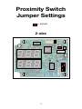
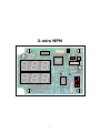
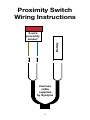
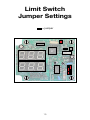
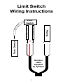
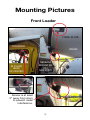
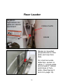
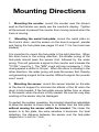
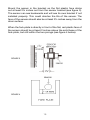
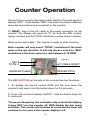
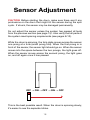
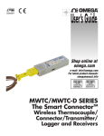
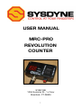
User Manual
MRC-PRO
REVOLUTION
COUNTER
SYSDYNE
1055 Summer St., 1st Floor
Stamford, CT 06905
1
2
Contents
4 Introduction
5 Components
6 Proximity Switch Jumper Settings
8 Proximity Switch Wiring Instructions
10 Limit Switch Jumper Settings
11 Limit Switch Wiring Instructions
12 Mounting Pictures
14 Mounting Directions
16 Counter Operation
17 System Test
18 Sensor Adjustment
20 Troubleshooting
3
Introduction
Sysdyne’s MRC-PRO counter is a mixing revolution counter for
concrete trucks. The New York State Department of Transportation
has approved the MRC-PRO for use on all concrete truck mixers.
The MRC-PRO counter utilizes state-of-the-art technology to track
mixer revolutions per minute as well as the mixer direction. The
MRC-PRO counter will display the “Number of Drum Revolutions
at Speeds within the Mixing Range” as well as the “Total Number of
Drum Revolutions”. In addition, the MRC-PRO counter can show
the “Current barrel RPM” and the “Total Batch Mix Time”.
We along with our current customers stand by this technology
with full confidence. Due to its versatility, the MRC-PRO can
replace malfunctioning counters without complete system
replacement. The MRC-PRO counter will work with limit switches
as well as proximity-sensors of varying types (jumper and wiring
configurations included on pages 6-9). We are able to provide both
types of sensors, but in order to preset the counters for the proper
sensor type, we require customers to specify “limit” or “proximity”
on their purchase orders.
Please note that limit switches wear out quickly due to the physical
contact involved in their usage. As a result, limit switches require
frequent maintenance and/or replacement. The proximity-sensor
doesn’t require any physical contact; therefore, parts do not
wear out and the sensor lasts longer. We’ve received reports of
proximity-sensor systems lasting more than five years without any
problems, maintenance, or parts failure.
If any problems are encounter during installation please refer to the
troubleshooting section at the end of this manual.
4
Components
• Sysdyne’s MRC-PRO counter
• Proximity sensor
• Harness (for power to counter and sensor/switch connection)
• Fork-plate (for use with proximity sensor)
• Reset Cable (included upon request)
Sysdyne’s MRC-PRO counter can be used with a proximity sensor
or limit switch. The counter box is sealed and water-resistant for
protection against the elements. The installation harness attaches
to a plug which sends power to the counter and a sensor/switch
signal to the counter. The metal fork-plate is a must for use with the
proximity sensor and attaches to the drum. The metal fork-plate is
made of steel for welding, if necessary, and the solid base can be
modified for easy mounting. The AC reset cable is used to reset the
counter when a new batch enters the truck. The AC reset cable is
included upon request.
NOTE: Sysdyne provides a standard fork-plate. Please check
with Sysdyne if severe modification of the fork-plate is needed
for mounting! Certain parts of the fork-plate must not be
altered in order to guarantee proper and reliable operation of
the MRC-PRO counter system.
5
Proximity Switch
Jumper Settings
= jumper
2-wire
6
3-wire NPN
7
Proximity Switch
Wiring Instructions
Battery
2-wire
proximity
sensor:
+
Harness
cable
supplied
by Sysdyne
8
−
Battery
3-wire
proximity
sensor:
+
Harness
cable
supplied
by Sysdyne
9
−
Limit Switch
Jumper Settings
= jumper
10
Truck Chassis
∅
Battery
Shield #14
e
Limit
Switch
Normally open #13
Bar
e
W
ir
Limit Switch
Wiring Instructions
+
Harness
cable
supplied
by Sysdyne
11
−
Mounting Pictures
Front Loader
FORK-PLATE
COUNTER
IN PLAIN
VIEW
OF DRIVER
DRUM
SENSOR
MOUNTED
ON
SUPPORT
Sensor is at least
2” away from drum
to prevent metal
interference.
12
Rear Loader
SENSOR
MOUNTED ON
SIDE OF DRUM
SUPPORT
FORK-PLATE
DRUM
Sensor is mounted
perpendicular to forkplate (red cap face
first).
For most accurate
detection, sensor is
within 1” of fork-plate
and at least 2” above
solid bsse of forkplate. (See figures 3
and 4 on page 13).
13
Mounting Directions
1. Mounting the counter: mount the counter near the driver’s
seat so that he/she can easily see the counter’s display. Tighten
all the screws to prevent the counter from moving around when the
truck is moving.
2. Mounting the metal fork-plate: mount the metal plate on
the truck’s drum, and the sensor on the drum’s support, parallel
and facing the fork-plate (see pages 10 and 11 for front and rear
loaders).
It is important to mount the fork-plate in the right direction. When
the drum turns in the mixing direction, the smaller prong of the
fork-plate should pass the sensor first, followed by the wider
prong. This will generate a signal to the counter and increase the
“TOTAL” count by 1. The “MIX” count will only increase by 1 if the
mixing speed is within 6-18 rpm. When the drum is rotating in the
other direction, the wider prong will pass the sensor first, thereby
not generating a signal to the counter. Without a signal, the counter
won’t count.
3. Mounting the sensor: mount the sensor bracket on the side
of the drum’s support to minimize the effects of the tilt when the
drum is fully loaded. If the fork-plate moves farther from or closer
to the sensor when the drum is fully-loaded, the counter may stop
working or the sensor may be damaged.
To perfect the system operation, the bracket should be adjustable
to allow the sensor to move closer to or farther from the fork-plate
without moving the sensor within the bracket. The closer the
sensor is to the plate, the more sensitive it becomes. For best
detection, the distance between the sensor and the fork-plate
ranges from ½ inch to 1 inch.
14
Mount the sensor in the bracket so the flat plastic face sticks
out at least 2¾ inches out from the sensor bracket (see figure 3).
The sensor can see backwards and will see its own bracket if not
installed properly. This could shorten the life of the sensor. The
face of the sensor should also be at least 2½ inches away from the
drum surface.
When the fork-plate is directly in front of the flat, red plastic face of
the sensor should be at least 2 inches above the solid base of the
fork-plate, but still within the two prongs (see figure 4 below).
FIGURE 3
FIGURE 4
15
Counter Operation
Connect the counter to the power cable. Wait for the reset signal to
display “RES”. It will display “RES” only when the power cable has
been disconnected and reconnected to the counter.
To RESET, plug in the AC cable to the resert connector on the
counter. The display will revert to “0” for both the MIX number
(upper number) and the TOTAL revolution number (lower number).
Remove the reset cable. The counter is ready to start counting.
Note: counter will only count “TOTAL” revolutions if the drum
spins in the mix direction. It will only show a count for “MIX”
revolutions if the drum spins at a rate between 6-18 RPM.
Figure 5
MIX #
TOTAL #
AC CABLE RESET
HARNESS CABLE
RED BUTTON
The RED BUTTON on the side of the counter has two functions.
1. To display the drum’s current RPM and the time since the
counter’s last reset, hold the button down for 0.5 seconds.
2. To turn the counter’s display ON/OFF*, hold the button down for
2.5 seconds.
*To prevent tampering, the red button only controls the display;
it does NOT turn the counter off, NOR disable the mix count
and timer. The counter will continue to count and the timer will
continue to run, even if the counter display is off.
16
System Test
To preform a system test, wire and mount the sensor so that it can
be easily adjusted from ¼ inch to at least 1 inch from the surface
of the revolving fork-plate.
Power-up and reset the counter to show zeros (0:00) on the display.
Rotate the drum so that the fork-plate is at least 1 foot away from
the sensor. (This is to ensure the plate does not interfere with the
first counter system check.)
Check the back of the sensor to make sure the lights on the back
of the sensor are off.
Place a piece of steel (a screwdriver or wrench will do) directly on
the front plastic face of the sensor. Now look at the back of the
sensor again (where the wire comes out) to verify that a GREEN
light is on.
Slowly move the steel away from the sensor until the GREEN light
turns RED, and even further away until all lights are OFF.
The sensor works if the lights passed this test.
To check the connection between the sensor and the counter, put
the piece of steel back on the sensor to see a light come back on.
While the light is on, check the counter display for a red dot in the
bottom right corner of the display.
Pull the steel away from the sensor. When the sensor lights go off,
the red dot should also go off.
The connection works if the dot passed this test.
17
Sensor Adjustment
CAUTION: Before starting the drum, make sure there aren’t any
protrusions on the drum that might hit the sensor during the spin
cycle. If struck, the sensor may be damaged permanently.
Do not adjust the sensor unless the system has passed all tests
from the previous section (see page 15) . Also verify that all parts of
the system meet spacing requirements (see pages 8-10).
While the drum is spinning, the fork-plate moves across the sensor
one prong at a time (small prong first). When the first prong is in
front of the sensor, the sensor light should go on. When the sensor
moves into the space between the two prongs, the light goes off.
When the sensor moves across the second prong, the light goes
on, and off again once it has passed.
OFF → ON → OFF → ON → OFF
This is the best possible result. When the drum is spinning slowly,
it’s easier to see the separate blinks.
18
1. First, set the space between the sensor and the fork-plate to ½
inch. Start the drum at slow speed in the mixing direction. If the
counter is counting, bring the drum up to its highest speed. If the
counter still counts properly at high speed, skip to step 4. If the
counter is not counting at all, continue to step 2. If it will not count
at high speeds, skip to step 3.
2. Stop the drum. Start by adjusting the sensor bracket so there is
a ¼ inch space between the sensor face and the fork-plate. Start
the drum at slow speed in the mixing direction. If the counter is
counting, bring the drum up to its highest speed. If the counter
is counting, bring the drum up to its highest speed. If the counter
still counts properly at high speed, skip to step 4. If the counter is
not counting at all, or it will not count at high speeds, continue to
step 3.
3. Stop the drum. Now move the sensor bracket backward to
bring the sensor face another ⅛ inch away from the fork-plate (if
the sensor was ¼ inch away before, it should now be ⅝ away). If
the space between the sensor plate and the fork-plate is now more
than 1 inch, stop here and go back to step 1. Start the drum at a
slow speed in the mix direction. If the counter is counting, increase
the drum up to its highest speed. If the counter still counts properly,
check to make sure it will NOT count with the drum spinning in the
opposite direction. If so, continue to step 4.
4. Having come this far, there are only three more steps to finish:
a. Verify at a high drum speed that both the “MIX” and the “TOTAL”
displays show a count of drum revolutions.
b. Slow the drum below 6 RPM and verify that only the “TOTAL”
number counts the drum revolutions.
c. Finally, reverse the drum so it is spinning opposite to the mix
direction and verify that BOTH numbers are NOT counting.
The counter is now working properly.
19
Troubleshooting
Problem: Counter doesn’t display “RES” and power is connected.
Solution: Check the counter’s power source and cable.
Problem: Counter is on and resets, but no lights come on when
steel is near the sensor.
Solution: Check the sensor connection and cable.
Problem: Counter resets and lights go on but the counter doesn’t
count after the adjustment.
Solution: Make sure the fork-plate is mounted in the right direction
(in the mixing direction the sensor sees the narrow fork-post first).
Slow down the drum speed and see if the decimal point on the
counter display blinks twice each time the fork-plate passes the
sensor. Check mounting dimentions for the sensor.
Problem: The dot in the corner of the counter display doesn’t
flash every time the metal plate passes the sensor (when the drum
rotates in the mixing direction).
Solution: You might need to readjust the sensor, or the sensor
might not be functioning. Check the sensor connection.
Problem: The dot flashes, but neither the MIX number nor the
TOTAL revolution number change (when the drum rotates in the
mixing direction).
Solution: If you have a proximity sensor with a fork-plate, check to
make sure the sensor and the fork-plate are mounted and adjusted
properly. Check the sensor wiring. The counter might be configured
for a different type of sensor setup than what is on your truck.
Problem: There is a light on the back of the sensor even when the
fork-plate is more than a foot away from it.
Solution: First check if the face of the sensor is at least 2¾ inches
away from the sensor bracket. If so, make sure there is no other
20
metal within 2¾ inches of the sensor.
Problem: After adjusting the sensor you see two green blinks with
a red light in between.
Solution: Slowly back the sensor away rom the fork-plate until the
counter starts counting.
Problem: After adjusting the sensor you see one solid green or
solid red blink, and when you back the sensor away, the light goes
out completely.
Solution: The sensor may be too close to the solid base of the
fork-plate. Try mounting the sensor closer to the tips of the fork
prongs and redo the adjustment of the sensor.
Problem: After adjusting the sensor you see two red blinks no
matter how you adjust it.
Solution: Make sure the fork prongs pass directly in front of the
sensor and are parellel to the face of the sensor. Check all wiring
for good solid connections. The sensor might be bad. The system
will work like this, but it may be unreliable. Test the counter for
proper operation.
Problem: Counter counts in the wrong drum direction only.
Solution: The fork-plate is most likely mounted backwards. Check
“Mounting the Sensor” (pages 12-13) for proper plate arrangement.
Problem: Counter counts in both directions and sometimes twice
per revolution.
Solution: The counter is configured for the wrong type of sensor.
Call Sysdyne to verify and fix this.
Problem: It doesn’t work and I don’t know why.
Solution: Give us a call and we’ll figure it out.
SYSDYNE: 203-327-3649
1-877-SYSDYNE
21
Thank you
for choosing Sysdyne!
22