1
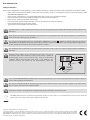
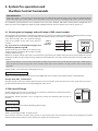
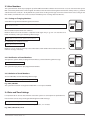
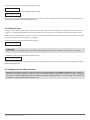
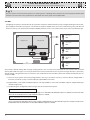
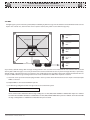
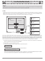
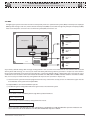
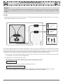
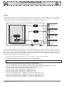
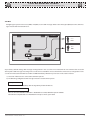
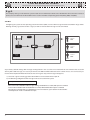
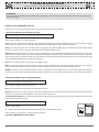
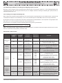
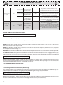
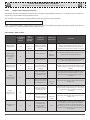
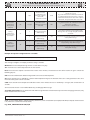
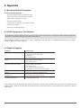
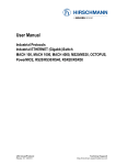
GSM CONTROL SYSTEM ESIM252 User Manual v1.0 Safety instructions Please read and follow these safety guidelines and assembly instructions in order to maintain safety of operators and people around: • • • • • • • GSM control system Esim252 (further referenced as the system) contains an integrated radio transceiver operating in GSM 850/900/1800/1900 MHz bands. Don’t use the system where it can interfere with other devices and cause any potential danger. Don’t mount the system next to medical equipment or devices, if they require so. Don’t use the system in hazardous environment. Don’t expose the system to high humidity, chemical environment or mechanical impacts. Don’t attempt to personally repair the system. System label is on the bottom side of the device. System Esim252 is a device mounted in limited access areas. Any system repairs must be done only by qualified, safety aware personnel. Mains power must be disconnected before any installation or tuning work starts. The system installation or maintenance must not be done during stormy conditions. The system must be powered by main 10-24V 50Hz ~200mA AC or 10-24V 200mA DC power supply which must be approved by LST EN 60950-1 standard and be easily accessible nearby the device. When connecting the power supply to the system, switching the terminals places does not have any affect. Any additional devices linked to the system Esim252 (computer, sensors, relays etc.) must be approved by LST EN 60950-1 standard. External power supply can be connected to AC mains only inside installation room with automatic 2-pole circuit breaker capable of disconnecting circuit in the event of short circuit or over-current condition. Open circuit breaker must have a gap between connections of more than 3mm and the disconnection current 5A. Phase Null PE AC/DC AC 230V 50 Hz/DC 24V ESIM252 USB cable Fuse F1 model MINISMDC050F 0.5A Blown fuse cannot be replaced by the user and the replacement fuses have to be exactly the same as indicated by the manufacturer. The device is fully turned off by disconnecting 2-pole switch off device of the external power supply or any other linked device that the system Esim252 is powered from. If you use I security class computer for setting the parameters it must be connected to earth. The WEEE (Waste Electrical and Electronic Equipment) marking on this product or its documentation indicates that in the EU the product must not be disposed of together with household waste. Copyright © “ELDES UAB”, 2009. All rights reserved. It is strictly forbidden to copy and distribute information in this document or pass to a third party without an advanced written authorization from “ELDES UAB”. “ELDES UAB” reserves the right to update or modify this document and/or related products without a warning. Hereby, ELDES UAB declares that this GSM CONTROL SYSTEM Esim252 is in compliance with the essential requirements and other relevant provisions of Directive 1999/5/EC. The declaration of conformity may be consulted at www.eldes.lt Limited Liability The buyer must agree that the system will reduce the risk of fire, theft, burglary or other dangers but does not guarantee against such events. “ELDES UAB” will not take any responsibility regarding personal, property or revenue loss while using the system. “ELDES UAB” responsibility according to local laws does not exceed value of the purchased system. “ELDES UAB” is not affiliated with GSM operators providing cellular services therefore is not responsible for the quality of cellular services. Manufacturer Warranty The system carries a 24-month warranty by the manufacturer “ELDES UAB”. Warranty period starts from the day the system has been purchased by the end user. The warranty is valid only if the system has been used as intended, following all guidelines listed in the manual and within specified operating conditions. Receipt with purchase date must be kept as a proof. The warranty is voided if the system has been exposed to mechanical impacts, chemicals, high humidity, fluids, corrosive and hazardous environment or other force majeure factors. Package Content: The system Esim252.................... 1 pcs Esim252 user manual.................. 1 pcs GSM antenna................................. 1 pcs Fastening holders......................... 3 pcs About User Manual This document describes GSM control system Esim252, its operation and installation. It is very important to read User Manual before start using the system. A quick start guide is located in first two chapters. Chapter 3 and 4 describe additional system capabilities. CONTENT 1. General Information 1.1 1.2 1.3 1.4 1.5 1.6 Function........................................................................................................4 Operation Description..............................................................................4 Technical Specifications ..........................................................................5 Connector Functionality..........................................................................5 Connection Circuit.....................................................................................6 System Installation....................................................................................7 2. System Pre-operation and the Main Control Commands 2.1 2.2 2.3 2.4 Selecting device language and verification of SMS central number............................................8 Password Change ......................................................................................8 User Numbers..............................................................................................9 2.3.1 Saving or Changing Numbers ...............................................9 2.3.2 Verification of Saved Numbers..............................................9 2.3.3 Deletion of Saved Numbers. ..................................................9 Date and Time Settings ...........................................................................9 3. Additional System Capabilities 3.1 Renaming Zones and Controlled Output....................................... 10 3.2 Enabling/Disabling Zones.................................................................... 10 3.3 Info on Status SMS.................................................................................. 11 3.4 Blocking Unknown Numbers.............................................................. 11 3.5 Remote Microphone Listening.......................................................... 12 3.6 Managing C1 and C2 Controlled Outputs. Timer........................ 12 3.7 SMS Message Delivery to Multiple Users...................................... 12 3.8 Calling all users....................................................................................... 13 3.9 Configuration for advanced users.................................................... 14 3.9.1 Additional possibilities of configuring zones (inputs) alarm and restore........................................ 25 3.9.2 Additional possibilities of controlling and configuring controller C1 (relay output)......................... 27 3.9.2.1 Settings of the output controlled by calls......... 27 3.9.2.2 Settings of the output controlled by SMS messages...................................................... 28 3.9.2.3 Output control settings by event time............... 30 4.Appendix 4.1 Restoring Default Parameters. ........................................................... 32 4.2 „ELDES Configuration Tool“ software.............................................. 32 4.2 Technical Support................................................................................... 32 1. General Information 1.1 Function ESIM252 is a micro controller based device intended to inform users about the alarm in automatic or security systems. In addition it can control up to two electric appliances. 1.2 Operation Description Description of factory default settings. GSM control system ESIM252 operates over GSM network 24/7, i. e. it always reacts to the incoming signal. In case any input is violated, the system sends an SMS message and/or calls to the preset user phone numbers. SMS message with the name of the violated zone will continue to be sent until successful delivery to one of the users or until it is delivered to all users. The system continues to call until one of the five users answers the call, rejects the call or until the call is ended by the GSM service provider. If the user answers the call, the system activates microphone (must be connected to ESIM252) for listening on what is happening in the secured premises. When using audio feature in case of input alarm or restore event the user will be able to listen to particular sound record uploaded to the ESIM252 device memory. After the end of the sound record, the system activates the microphone for listening on what is happening in the secured premises. After „hanging the phone“ or after the end of the call (duration - 1 min.), the system will return to the previous state. Please, refer to ELDES Configuration Tool software Help section for more details on audio feature. Up to 2 electric appliances connected to ESIM252 can be controlled from a mobile phone. This feature allows to turn on/off heating, lighting, lift the gates, blinds etc. The system ignores incoming calls from unknown phone numbers and SMS messages with wrong password. List of other configurable system possibilities. Input types Ways of initiating an event Normally open (NO) Operational only when the signal is switched. Event when an input is violated (Alarm) Phone call initiated and/or SMS is delivered to user (-s) when the signal is transmitted to an input. Event when a zone is restored (Restore) Phone call initiated and/or SMS is delivered to user (-s) when the previously transmitted input signal disappears. Impulse counting Input is considered as violated only if the number of the preset impulses in the input is exceeded. Max. value is 4294967295 impulses. SMS Ways of notifying about an event Phone Call Turning on/off by SMS Ways of controlling outputs (relays) Event log 4 Operational only when the signal is transmitted. Normally closed (NC) Turning on/off by a call The ways of notifying users about events occurred in the particular input can be carried out only SMS, only a phone call or a combination of both can be chosen. Besides, any of the users can be assigned to be informed in case a particular input is violated or restored or both. Various combinations of informing can be assigned for each user and input. When features SMS All and Call All are enabled, the system sends SMS messages and rings to all preset users starting with User1 despite the fact that the call was answered or rejected etc. Examples: User NR1 wants to be informed by SMS in case input Z3 is violated, but does not want to be informed when input Z3 is restored. User NR3 wants to be informed by SMS and phone call in case input Z2 is violated, but wants to be informed only by SMS in case of Z2 restore event. The outputs can be turned on/off by sending the command by SMS message. You can turn on/off: 1. for a permanent status 2. for a set period 3. for a set hour 4. repeating turning on/off. The outputs can be turned on/off by calling. You can turn on/off: 1. for a permanent status 2. for a set period 3. toggle (output status changes after each call) Automatic turning on at the preset hour Outputs can be turned on for a set period at a set hour. E. g. the relay is turned on at 18:00 and it is on for 5 hours. After 5 hours it turns off automatically notifying the user about that. Event log feature List of occurred events by date and time - zone alarm/restore, output on/off etc. 1.3 Technical Specifications Electrical and mechanical specifications Supply voltage 10-24V 50Hz ~ 200mA max / 10-24V 200mA max 50mA max 850/900/1800/1900 MHz 4 1 Voltage: 0... 1.6V; current: -0.8... -0.4mA Voltage: 5... 50V; current: 0.17.... 1.7mA 2 Relay. Normally open (NO) 24V 1A / 24V 50Hz ~0,5A 82x63x20mm -20…+55oC (-30...+55oC with limitations) Current used in standby mode GSM modem frequency Number of “low” level (negative) inputs Number of “high” level (positive) inputs Allowable „low“ level (negative) input values Allowable „high“ level (positive) input values Number of outputs Output type Relay output maximum commutating values Dimensions Operating temperature range 1.4 Connector Functionality Short explanation of the main units USB SIM CARD ANT GSM MODEM GSM MODEM SIM CARD LED DEFAULT ANT LED1 LED2 MIC DEFAULT D1 D2 F1 AC/DC RELAY1 RELAY2 COM Z5 Z4 Z3 Z2 Z1 Picture 1 USER MANUAL ELDES ESIM252 V1.0 USB F1 GSM network 850/900/1800/1900 MHz modem SIM card Light-emitting diodes indicator Connectors (D1 and D2) for restoring default settings GSM antenna SMA type connector Mini USB connector Fuse Connector functionality Labeling AC/DC RELAY1 RELAY2 COM Z5 Z4 Z3 Z2 Z1 Explanation Power supply pins Dry relay contact. Normally open (NO) Dry relay contact. Normally open (NO) Common pin “Low” level input Z5 “Low“ level input Z4 “Low” level input Z3 “High” level input Z2 “Low” level input Z1 5 LED indicators functionality LED1 LED2 Indicates SIM card status Indicates network status LED1 status OFF Meaning SIM card is working properly ON SIM card error LED2 status OFF Meaning No network connection Blinking 3 times per second Poor network connection Blinking 1 time per second Medium network connection ON Excellent network connection 1.5 Connection Circuit USEFUL INFORMATION When choosing GSM provider, it is worth inquiring whether the service is used in security application assuring fast and reliable SMS message delivery and phone call connection. USEFUL INFORMATION When choosing GSM cellular provider, it is worth inquiring whether the service is used in security application assuring fast and reliable SMS message delivery and phone call connection. Esim252 and alarm system COM must be connected. Inputs Z1, Z3, Z4, Z5 are connected to alarm system outputs if outputs are implemented as open collector circuit or any other circuit and if it commutes with COM. It is also possible to connect Z1, Z3, Z4, Z5 inputs to, for instance, motion sensor or any other sensor as well as automatics device provided the inputs are commuted with COM. Input Z2 is commuted with a “high level” impulse. Impulse duration is >600ms. GSM Control System ESIM252 AC/DC RELAY1 RELAY2 COM Z5 Z4 Z3 Z2 AC/DC Metal box PE contact Z1 Fuse 500 mA ~10-24V Picture3 AC power supply connection circuit PGM1 PGM2 PGM3 PGM4 PGM5 AUX- AUX+ HIGH LEVEL Alarm system or other appliance Picture 2 6 ~230V 50Hz 1.6 System Installation The system can be installed only in a metal or non-flammable plastic enclosure. If the metal enclosure and transformer is used it is necessary to ground the enclosure using yellow/green colour cable. For the connection of 230V transformer use 3x0.75 mm2 1 thread double isolated cable. The primary circuit of the transformer must be connected through 0.5A fuse. 230V power supply cables cannot be grouped with low voltage cable group. For the connection of power supply and output connectors use 1 thread 2x0.75 mm2 cable. For the connection of input/output connectors use 0.50 mm2 1 thread cable. 1. Fasten the system in the box using fastening holders. 2. Place SIM card in the holder but make sure that SIM card PIN code is disabled. (PIN code can be disabled by putting SIM card into mobile phone and following proper menus). SIM card should not have any remaining SMS messages. 3. Connect the circuit as shown in fig. No 2. Power supply cables are connected last). When connecting Esim252 to alarm system power supply, usually the security system AUX output is used. 4. When AC power supply (ground transformer) is used connect according to circuit no. 3. In this case you do not need to connect any other power supplies. 5. The system will start in less than a minute. LED2 indicator should be blinking or be ON indicating connection to GSM. USER MANUAL ELDES ESIM252 V1.0 7 2. System Pre-operation and the Main Control Commands VERY IMPORTANT!!! Underscore symbol ‘_’ in this manual is used to represent space. When writing SMS messages, every underscore symbol should be replaced by single space symbol. XXXX – means password. Do not leave any space at the beginning and the end of the message. To set ESIM252 system parameters easier and quicker you can use the computer, USB cable or remote device configuration over GPRS connection and configuration software „ELDES Configuration Tool“. For more details, please, refer to chapter 3.2. 2.1 Selecting device language and verification of SMS central number The language in which the device communicates with the user can be chosen before changing factory default password. To change the language in the system that is already configured reset default settings as described in 3.1 appendix. Send SMS message with the required language code to the number of the SIM card inserted in Esim252. E.g., if you want to set the English language send the following SMS message: EN Table of possible languages Language Code lithuanian LT english EN ESIM 252 30-60 seconds later you should get an SMS message: russian RU „English language confirmed.“ Go to chapter 2.2 upon reception of this message. Otherwise check for network connection and call Esim252 system from your mobile and wait until the system drops the call. You should get an SMS message asking to change default password. Otherwise check for network connection and change SMS central number. SMS central number is saved in SIM card, therefore if SIM card has been used to send SMS messages with a mobile phone, then you don’t’ need to change SMS central number. Often SMS central number is already saved in SIM card by cellular operator. Central number can be entered by sending SMS message: XXXX_SMS_+37011111111 XXXX – is a password. Default password is four zeros: 0000. SMS central number is provided by cellular network provider. Example: 0000_SMS_+37069899992 Message should be sent to the number of SIM card which is placed into the system. If all went correct, the system will send a message: SMS central number has been successfully changed to +37011111111 2.2 Password Change All SMS commands start with a password, please memorize it. Manufacturer default password is four zeros 0000, which is necessary to change. ESIM 252 0000_ PSW_XXXX Manufacturer default password can be changed by sending the following SMS message to Esim252: 0000_PSW_XXXX To replace your password, send the following SMS message: YYYY_PSW_XXXX XXXX is any four digit number except four zeros. Non-numerical characters like dots, colons, spaces are not allowed. YYYY is the old system password. If you forgot the password, default manufacturer password can be restored, see chapter 4.1 for more details. 8 2.3 User Numbers The system Esim252 allows to pre-program up to five different mobile numbers which will have access to and control the system. NR1 is mandatory while others can be skipped. All numbers must be entered starting with international country code, e. g. national code for Lithuania is 370, UK – 44. By default the system starts sending all messages and in the event of alarm starts calling on the first number, and if the first call is unsuccessful, it immediately tries reaching subscriber No2 etc. 2.3.1 Saving or Changing Numbers Send SMS message with the following text to Esim252: XXXX_NR1:37011111111_NR2:37011111111_NR3:37011111111_NR4:37011111111_ NR5:37011111111 ESIM 252 XXXX_ NR1:370 11111111_ NR4:370 11111111 ESIM 252 XXXX_ NR3:370 11111111 Ones should be replaced with user numbers. Numbers don’t have to be entered in sequential order right away. E. g. user can enter first and fourth number by sending the following SMS message: XXXX_NR1:37011111111_NR4:37011111111 Or individually one number at a time: XXXX_NR3:37011111111 Numbers can be changed same way as described above. New number will overwrite old one, therefore no erasing is necessary. 2.3.2 Verification of Saved Numbers To inquire the system about pre-programmed numbers, send the following SMS message: ESIM 252 XXXX_ HELPNR ESIM 252 XXXX_ NR3:DEL ESIM 252 XXXX_ 2009.01. 01_14:15 XXXX_HELPNR The system will reply with all pre-programmed numbers. 2.3.3 Deletion of Saved Numbers To erase NR2-NR5, send the following SMS message: XXXX_NR2:DEL_NR3:DEL_NR4:DEL_NR5:DEL E. g. XXXX_NR3:DEL The system will not allow erasing first number NR1. It can only be modified. 2.4 Date and Time Settings It is important to set correct date and time so that the system can send reports at specified times. Date and time can be set by sending the following format SMS message: XXXX_MMMM.mn.dd_va:mi where MMMM means year; mn - month; dd - day; va - hour; mi - minutes E. g. XXXX_2009.01.01_14:15 USER MANUAL ELDES ESIM252 V1.0 9 3. Additional System Capabilities 3.1 Renaming Input Alarm/Restore Texts & Оutput Нames Manufacturer initially set the following input alarm/restore texts and output names: input Z1 alarm text - Zone1 Alarm, restore text - Restore1; input Z2 - Zone2 Alarm, restore text - Restore2; 0 input Z3 - Zone3 Alarm, restore text - Restore3; input Z4 - Zone4 Alarm, restore text - Restore4; input Z5 - Zone5 Alarm, restore text - Restore5; output C1 name - Controller1; output C2 name - Controller2 E. g. in case input Z1 is violated, the system sends SMS message with the text: Zone1 Input alarm text Input alarm text is changed by sending the following SMS mesaage: XXXX_Z1:NewAlarmText;Z2:NewAlarmText;Z3:NewAlarmText;Z4:NewAlarmText;Z5:NewAlarmText; E. G. XXXX_Z1:Intrusion though the door;Z2:Fire sensor alarm; Texts can be changed all at once for all inputs, several of them or one by one. Maximum text for one input text is 24 characters. The space is equal to one character. Each new text must be followed by a semi colon. As semi colon is used for separating texts for different inputs. It cannot be used in the middle of alarm texts, it can only be used at the end. Texts cannot be the same as configuration and control commands, such as - ON, OFF, STATUS etc. ESIM 252 XXXX_Z1: trespaced; Z2: triggered fire detector; Input restore text If you want to be notified by an SMS message when a violated zone is restored Restore mode must be turned on. The mode is turned on by sending a particular SMS command. Please refer to chapter 3.9 or configuration program. Input restore text is changed by sending the following SMS mesaage: XXXX_ZR1:NewRestoreText;ZR2:NewRestoreText;ZR3:NewRestoreText;ZR4:NewRestoreT ext;ZR5:NewRestoreText; Output name can be changed by sending the following SMS message: XXXX_Cx:NewControllerName x - output number; possible values 1 - C1 or 2 - C2. Output name cannot be followed by a semi colon. You cannot change input alarm/restore text and output names at the same time. E. g. XXXX_C1:PUMP 3.2 Enabling/Disabling Inputs NOTE Manufacturer set all the inputs activated, i. e. in mode ON. USEFUL INFORMATION The inputs can be enabled/disabled together or separately one by one. Enabling Input Any input can be enabled by sending the following SMS message: XXXX_Z1:ON;Z2:ON;Z3:ON;Z4:ON;Z5:ON; 10 ESIM 252 XXXX_C1: PUMP Disabling Input Any input can be disabled by sending the following SMS message: XXXX_Z1:OFF;Z2:OFF;Z3:OFF;Z4:OFF;Z5:OFF; ESIM 252 XXXX_ WINDOWS: OFF; E. g. XXXX_Z2:ON; or XXXX_WINDOWS:ON; or XXXX_Z2:OFF; or XXXX_WINDOWS:OFF; 3.3 Info on Status SMS The system ESIM252 can any time be inquired about signal strength and the status of inputs at the time when SMS message is sent. At the same time system test is performed. If the answer to the request has been received, it means the system finely operates. It is also useful for those using prepayment service – you can check if the credit in the account is sufficient for sending an SMS message. Send the following SMS message: XXXX_INFO The reply SMS will have following info: e. g. 2008.08.07 11:15 Signal strength satisfactory. Z1:OK/ALARM Z2:OK/ALARM Z3:OK/ALARM Z4:OK/ALARM Z5:OK/ALARM where OK means that there is no alarm in a particual input (restored). ALARM – the particular input is violated. By default, this status SMS message will be sent daily at 11:00 in the morning. These parameters can be configured by sending the following SMS message: ESIM 252 XXXX_ INFO:01. 10 XXXX_INFO:PP.VV PP – message period in days, valid values [00-10]. VV - time when message is sent, valid values [00-23]. E. g. XXXX_INFO:01.10 means that status message will be sent every 1 day at 10:00. ESIM 252 XXXX_ INFO:0.2 If PP value is 0, and VV in the range of [1-23], then periodic status messages will be sent multiple times per day, with period being specified as VV time. E. g. XXXX_INFO:0.2 means that status message will be sent every 2 hours. To disable periodic status messages send the following SMS message: XXXX_INFO:00.00 The status messages will not be sent until enabling or restoring default parameters or receiving previously described XXXX_ INFO:PP.VV SMS message. 3.4 Blocking Unknown Numbers By default Esim252 system can be controlled from any of the preset users NR1 - NR5. However, the user can access the system and control parameters and outputs from any number as long as password is known. To enable this feature send the following SMS message: XXXX_STR:ON To disable this feature send the following SMS message: XXXX_STR:OFF USER MANUAL ELDES ESIM252 V1.0 11 3.5 Remote Microphone Listening NOTE To enable this feature it is necessary to connect microphone connector to MIC slot. The microphone is additional equipment tha can be purchased in trading centers. You can listen to what is going on in the secured premises by sending the following SMS message: XXXX_MIC The system will ring the sender of the received SMS, and upon answering the call, the user can listen to any sounds in the building. The phone call must be answered within 20 seconds otherwise the system will stop trying and return to previous state. 3.6 Managing C1 & C2 Outputs. Timer. GSM control system ESIM252 contains two outputs C1 and C2. It can be used to control various electric appliance, such as electric pumps, heating, lighting etc. When the output (-s) is turned on, the relay connectors of the output are in NC state (normally closed).(). The output is turned on by sending the following SMS message: XXXX_Cx:ON x - output number; possible values 1 - C1 or 2 - C2. The output is turned off by sending the following SMS message: ESIM 252 XXXX_ PUMP: ON XXXX_Cx:OFF x - output number; possible values 1 - C1 or 2 - C2. Instead of C1 or C2 it is also possible to use real output name. E.g.. XXXX_PUMP:ON Timer GSM control system ESIM252 has internal timer. This feature allows any output to be turned on or off for a specified time period. The following SMS command should be sent: XXXX_Cx:ON/OFF:vv.mm.ss x - output number; possible values 1 - C1 or 2 - C2. ON – output enabled. OFF – disabled vv – hours, valid values [00-23] mm – minutes, valid values [00-59] ss - seconds, valid values [00-59] It is not allowed to have all values equal zeros. Zeros it is not allowed to have all values equal E. g. to switch the pump on for 01 minutes and 23 seconds, send SMS XXXX_PUMP:ON:00.01.23 ESIM 252 XXXX_ PUMP: OFF:00. 01.23 If the pump was enabled before and user want to disable it for 01 minute and 23 seconds, send SMS XXXX_PUMP:OFF:00.01.23 If you want to use more capabilities of the outputs, such as TOGGLE, automatic output control at a particular, use configuration software „ELDES Configuration Tool“ or refer to chapter 3.9.2 3.7 SMS Message Delivery to Multiple Users Upon activated alarm in security system, ESIM252 SMS messages are repeatedly sent until first successful delivery to one of the users. The system starts with NR1 and if delivery fails, it follows with NR2 etc. It is also possible to set the system so that it sends SMS message to all preset users in the system. 12 To enable this function send the following SMS message: XXXX_SMSALL:ON To disable this function send the following SMS message: XXXX_SMSALL:OFF If you want to configure SMS message delivery only for particular users or only for particular inputs, please, refer to chapter 3.9 or use configuration program ELDES Configuration Tool. 3.8 Calling all users During the alarm, Esim252 system starts calling NR1. If the call to NR1 was unsuccessful or the subscriber was out of network coverage the call is forwarded to NR2 etc. If the user rejected the call or answered te call during the alarm the system stops calling. However, you can set the system to call all users entered in the system regardless of the fact whether the user answered or rejected the call, was out of network coverage or was engaged. To turn on this feature send the following SMS message: XXXX_CALLALL:ON ATTENTION! When this feature is enabled it will not be possible to stop calling the next user in the sequence even if the call is answered. To disable this function send the following SMS message: XXXX_CALLALL:OFF If you want to configure calling only to particular users or only for particular zones, refer to chapter 3.9 or use configuration program ELDES Configuration Tool. 3.9 Configuration for advanced users All features described in chapter 3.9 of the user manual can be configured using “ELDES Configuration Tool“ software. In case if there is no possibility of connecting the device to the computer via USB or if you want to change the settings remotely you can do this via remote configuration feature over GPRS using “ELDES Configuration Tool“ or via SMS messages. We recommend changing the settings by SMS only for advanced users. USER MANUAL ELDES ESIM252 V1.0 13 F O R A D VA N C E D U S E R S All these features can be configured using program “ELDES Configuration Tool“ E. g. 1 The user wants to connect Esim252 system to an existing alarm in a building where enterprise A and and enterprise B work. Both enterprises use the same alarm system that has two inputs. The alarm system has 5 outputs PGM. Task NO1: Configuring the system so that the director of a particular enterprise is informed about security arming depending on which enterprise employee armed the alarm system. The director of enterprise A (NO1) wants to receive an SMS message only and does not want to receive any calls, the director of enterprise B (NO2) wants to receive a call and does not want to receive any SMS messages. PIR PIR Enterprise A Director A NO1 Enterprise B Director B NO2 Alarm system PGM1 PGM2 Alarm SMS ESIM151 Alarm Calls Worker A NO4 Worker B NO5 Janitor GATES Janitor NO3 As per factory default settings SMS message sending feature in the case of alarm is enabled for all users until the first successful delivery of the SMS message, it is necessary to remove the users that should not receive any alarm messages. Besides, as per factory default settings, calling feature in the case of alarm is also enabled for all users therefore call function must be disabled for all users except user NO2. a) First of all alarm system unit must be programmed in the way so that when security is armed in office A, output PGM1 is turned on, and when security is armed in office B, output PGM2 is turned on. b) Output PGM1 is connected to ESIM252 input Z1, and output PGM2 is connected to ESIM252 input Z2. (output PGM2 type should be “high level”). c) The following two configuration SMS messages must be sent to Esim252 system: XXXX_SMSEXTRA:Z1:SC2345,CC12345 where SC2345 means that alarm SMS message sending to users NO2-NO5 is disabled after input Z1 is violated. CC12345 means that alarm calls are disabled for all users NO1-NO5 after input Z1 is violated. XXXX_SMSEXTRA:Z2:SC12345,CC1345 14 where SC12345 means that alarm SMS message sending is disabled for all users NO1-NO5 after input Z2 is violated. CC1345 means that all alarm calls are disabled for users NO1, NO3-NO5 after input Z2 is violated. F O R A D VA N C E D U S E R S All these features can be configured using program “ELDES Configuration Tool“ Task NO2: Configuring the system so that the janitor (NO3) is notified by by SMS message and call about the violated PIR movement sensor‘s input in the secured area; and when the sensor‘s input is restored, the janitor receives SMS message only. PIR PIR Enterprise A Director A NO1 Enterprise B Director B NO2 Alarm system PGM3 Worker A NO4 ESIM151 Worker B NO5 Janitor GATES Alarm SMS/Calls Restore SMS Janitor NO3 As per factory default settings SMS message sending feature in the case of alarm is enabled for all users until the first successful delivery of the SMS message, it is necessary to remove the users that should not receive any alarm messages. Besides, as per factory default settings, calling feature in the case of alarm is also enabled for all users therefore call function must be disabled for all users except user NO3. SMS message sending feature must also be enabled for user NO3 when input Z3 is restored. a) First of all alarm system unit must be programmed in the way so that when PIR movement sensor‘s input is violated, output PGM3 is activated. b) Output PGM3 is connected to ESIM252 input Z3. c) The following configuration SMS message must be sent to Esim252 system: XXXX_SMSEXTRA:Z3:SC1245,CC1245,SE3 where SC1245 means that alarm SMS message sending to users NO1, NO2, NO4 and NO5 is disabled after input Z3 is violated. CC1245 means that alarm call feature is disabled for users NO1, NO2, NO4 and NO5 after input Z3 I is violated. SE3 means that SMS message sending feature is enabled for user NO3 after Z3 input is restored. USER MANUAL ELDES ESIM252 V1.0 15 F O R A D VA N C E D U S E R S All these features can be configured using program “ELDES Configuration Tool“ E. g. 1 The user wants to connect ESIM252 system to an existing alarm system in a building where enterprise A and enterprise B work. Both enterprises use the same alarm system unit that has 2 inputs and 5 outputs PGM. Task NO3: Configuring the system so that the intrusion to enterprise A premises is reported to the janitor (NO3) and enterprise A employee (NO4) by SMS messages and calls. Enterprise A employee (NO4) wants to receive a call only in the case if the janitor (NO3) does not answer the call, is out of network coverage or at that time the janitor’s telephone line is engaged. PIR PIR Enterprise A Director A NO1 Enterprise B Director B NO2 Alarm system PGM4 Worker A NO4 ESIM151 Alarm SMS/Calls Worker B NO5 Janitor GATES Alarm SMS/Calls Janitor NO3 As per factory default settings SMS message sending feature in the case of alarm is enabled for all users until the first successful delivery of the SMS message, it is necessary to enable mandatory SMS message delivery (see more in chapter 3.7) and to remove the users who should not receive alarm messages. Besides, as per factory default settings, calling feature in the case of alarm is also enabled for all users therefore call function must be disabled for all users except users NO3 and NO4. As per factory default settings in the case of alarm the system rings until the first answered call, therefore in this case nothing should be configured. a) First of all alarm system unit must be programmed in the way so that when security sensors of enterprise A are violated, the signal is transmitted to alarm system unit‘s output PGM4. b) Output PGM4 is connected to ESIM252 input Z4 c) The following configuration SMS messages must be sent to Esim252 system: XXXX_SMSALL:ON where SMSALL enables mandatory SMS message delivery feature for all users. XXXX_SMSEXTRA:Z4:SC125,CC125 Where SC125 means that alarm SMS message delivery feature is disabled for users NO1, NO2 and NO5 after input Z4 is violated. CC125 means that alarm calls are disabled for users NO1, NO2 and NO5 after input Z4 is violated. 16 F O R A D VA N C E D U S E R S All these features can be configured using program “ELDES Configuration Tool“ Task NO4: Configuring the system so that the intrusion to enterprise B premises is reported to the janitor (NO3) and enterprise B employee (NO5) by SMS messages and calls, and the director of enterprise B (NO2) receives SMS message only. Enterprise B employee (NO5) must receive the phone call even in the case when the janitor (NR3) answers the call. PIR PIR Enterprise A Director A NO1 Enterprise B Director B NO2 Alarm system PGM5 Alarm SMS ESIM151 Alarm SMS/Calls Worker A NO4 Worker B NO5 Janitor GATES Alarm SMS/Calls Janitor NO3 As per factory default settings SMS message sending feature in the case of alarm is enabled for all users until the first successful delivery of the SMS message, it is necessary to enable mandatory SMS message delivery (see more in chapter 3.7) and to remove the users who should not receive alarm messages. Besides, as per factory default settings, calling feature in the case of alarm is also enabled for all users therefore call function must be disabled for users NO1, NO2 and NO4, and left enabled for users NO3 and NO5. Also, it is necessary to enable mandatory calling feature for all preset users (see more in chapter 3.8). a) First of all alarm system unit must be programmed in the way so that when security sensors are violated the signal must be transmitted to alarm system unit‘s output PGM5. b) Output PGM5 is connected to ESIM252 input Z5 c) The following three configuration SMS messages must be sent to Esim252 system: XXXX_SMSALL:ON where SMSALL enables mandatory SMS message delivery feature for all users. XXXX_CALLALL:ON where CALLALL enables mandatory calling feature for all users. XXXX_SMSEXTRA:Z5:SC14,CC124 where SC14 means that alarm SMS message sending feature is disabled for users NO1 and NO4 after input Z5 is violated. CC124 means that alarm calls are disabled for users NO1, NO2 and NO4 after input Z5 is violated. USER MANUAL ELDES ESIM252 V1.0 17 F O R A D VA N C E D U S E R S All these features can be configured using program “ELDES Configuration Tool“ E. g. 2. The user wants to connect ESIM252 system to the outputs PGM of an existing alarm system. House area is entered through automatically controlled gates. There are 5 users in total. NO1 is the housekeeper, NO2 is a neighbour, NO3-NO5 are family members. Task NO1: Configuring the system so that house alarm activation is reported to the housekeeper (NO1) by SMS message and a call as well as to the neighbour (NO2) but by SMS message only. PIR PIR Housekeeper NO1 Alarm SMS/Calls Neighbour NO2 Alarm SMS Alarm system Family members: PGM ESIM151 PIR PIR NO3 NO4 NO5 GATES As per factory default settings SMS message sending feature in the case of alarm is enabled for all users until the first successful delivery of the SMS message, it is necessary to enable mandatory SMS message delivery (see more in chapter 3.7) and to remove the users who should not receive alarm messages. Besides, as per factory default settings, calling feature in the case of alarm is also enabled for all users therefore call function must be disabled for users NO2-NO5 and left enabled for NO1 only. a) First of all alarm system unit must be programmed in the way so that when security sensors are violated the signal must be transmitted to alarm system system unit output PGM. b) Output PGM is connected to ESIM252 input Z1 c) The following two configuration SMS messages must be sent to Esim252 system: XXXX_SMSALL:ON where SMSALL enables mandatory SMS message delivery for all users. XXXX_SMSEXTRA:Z1:SC345,CC2345 Where SC345 means that alarm SMS message sending is disabled for users NO3, NO4 and NO5 after input Z1 is violated. CC2345 means that alarm calls are disabled for all users except NO1 after input Z1 zone is violated. 18 F O R A D VA N C E D U S E R S All these features can be configured using program “ELDES Configuration Tool“ Task NO2: Configuring the system so that house gates could be opened via free calls by the housekeeper (NO1) and his family members (NO3), (NO4) and (NO5). After every successful gate opening the user NO5 wants to receive a confirmation call (Call Back) the duration of which is 3 seconds, and the user NO3 wants to receive a confirmation SMS message. Control Call Confirmation SMS Gate controller ESIM151 Housekeeper NO1 Family member NO3 Family member NO4 Confirmation Call 3 sek. Family member NO5 GATES As per factory default settings C1 output control via calls is disabled for all users, it is necessary to enable this feature and to set the users who will be able to control the output. Besides, it is also necessary to set output status for every user when he/she makes a call to the system. In this case the output must be turned on and the duration must be 1 second; afterwards the output returns to the previous state. Call Back feature must be enabled for user NO5 and it is necessary to choose the length parameters for that call. Also, confirmation SMS messages have to be enabled for user NO3. a) First of all Esim252 system relay output has to be connected to the connectors of gate control unit. b) The following configuration SMS message must be sent to Esim252 system: XXXX_SMSEXTRA:COC1:CE1345,CS5,CT513,SS3,MS10,MS30,MS40,MS50,MS1T0.0.1,MS3T0.0.1,MS4T0.0.1,MS5T0.0.1 where COC1 means C1 output control by call is enabled for users NO1, NO3-NO5. CS5 means that Call Back feature is enabled for user NO5 after output C1 status changes. CT513 means that user NO5 will receive a confirmation call when the output gets activated and call duration is 3 seconds. SS3 means that user NO3 will be informed about output C1 status change by SMS message. MS10 means that the output is activated when user NO1 calls the system. MS30 means that the output is activated when user NO3 calls the system. MS40 means that the output is activated when user NO4 calls the system. MS50 means that the output is activated when user NO5 calls the system. MS1T0.0.1 means that output status is changed for 1 second when user NO1 calls the system. MS3T0.0.1 means that output status is changed for 1 second when user NO3 calls the system. MS4T0.0.1 means that output status is changed for 1 second when user NO4 calls the system. MS5T0.0.1 means that output status is changed for 1 second when user NO5 calls the system. USER MANUAL ELDES ESIM252 V1.0 19 F O R A D VA N C E D U S E R S All these features can be configured using program “ELDES Configuration Tool“ E. g. 3. The user wants to connect Esim252 system to the heating system of the house. Task No1: Configuring the system so that house heating system is turned on and turned off by the user (NO1) via free call. This user should also receive free information about successful turning on or turning off of the heating system. Flood detector User NO1 Heating Controller User NO2 ESIM151 Confirmation Call 3sek/10sek Control Call As per factory default settings C1 output control via calls is disabled for all users, it is necessary to enable this feature and to set the users who will be able to control the output – in this case it is user NO1. Besides it is also necessary to set output status for user NO1 when he/she calls the system. In this case you must set the system so that the output is turned on after one call and turned off after another one (Toggle) and so on. User NO1 needs to enable confirmation call (Call Back) feature and set the length parameters for that call. To differentiate whether the output was turned on confirmation call will be set to ring for 3 seconds and the confirmation call will ring for 10 seconds when the output was turned off. a) First of all ESIM252 system output C1 has to be connected to the connectors of heating controller unit. b) The following configuration SMS message must be sent to Esim252 system: XXXX_SMSEXTRA:COC1:CE1,CS1,CT113,CT1010,MS12 where COC1 means C1 output control by call is enabled for users NO1. CS1 means that confirmation call feature is enabled for user NO1 after output C1 status changes. CT113 means that user NO1 will receive a confirmation call when the output is turned on and call duration is 3 seconds. CT1010 means that user NO1 will receive a confirmation call when the output is turned off and call duration is 10 seconds. MS12 means that Toggle mode is activated for user NO1 which means that output status is changed with every call. 20 F O R A D VA N C E D U S E R S All these features can be configured using program “ELDES Configuration Tool“ Task No2: Configuring the system so that users (NO1) and (NO2) receive SMS message about a burst water pipe (flood) at home. SMS messages must be delivered to both users. Flood detector User NO1 Heating Controller User NO2 Alarm SMS ESIM151 Alarm SMS As per factory default settings SMS message sending feature in the case of alarm is enabled for all users until the first successful delivery of the SMS message and calling in the case of alarm is enabled for all users until the first answered call, calling feature in the case of alarm must be disabled for users NO1 and NO2. Mandatory SMS delivery to all users must also be enabled. a) First of all a flood sensor is connected to Esim252 input Z1. b) The following configuration SMS messages must be sent to Esim252 system: XXXX_SMSALL:ON where SMSALL enables mandatory SMS message delivery feature for all users. XXXX_SMSEXTRA:Z1:CC12 where CC12 means that alarm call feature is disabled for users NO1, NO2 after input Z1 violation. We make an assumption that users NO3-NO5 were not preset in the system at all. USER MANUAL ELDES ESIM252 V1.0 21 F O R A D VA N C E D U S E R S All these features can be configured using program “ELDES Configuration Tool“ E. g. 4. The company taking care of automatic systems needs to have information about critical breakdowns of mechanisms and has to quickly react and eliminate the breakdown. There are three members of operating personnel (NO1), (NO2) and (NO3). Task No1: Configuring the system so that operating personnel member (NO1) receives SMS message about the breakdown of gas boiler. Working normally a gas boiler transfers a signal, and when it breaks down the signal is not transmitted. Pump Worker NO1 Gas boiler Fault signal ESIM151 Alarm SMS Automatic system Worker NO2 Worker NO3 As per factory default settings SMS message sending feature in the case of alarm is enabled for all users until the first successful delivery of the SMS message, it is necessary to remove users NO2 and NO3 and disable alarm calls for all users. It is also necessary to invert Esim252 input from NO to NC mode so that alarm is given only when the signal disappears. a) First of all a signal indicating gas boiler breakdown isconnected to Esim252 input Z1. b) The following configuration SMS message must be sent to Esim252 system: XXXX_SMSEXTRA:Z1:SC23,CC123,LI1 22 where SC23 means that alarm SMS message sending is disabled for users NO2, NO3 input Z1 is violated. CC123 means that alarm calls are disabled for users NO1, NO2 and NO3 after input Z1 is violated. We make an assumption that users NO4-NO5 were not entered to the system at all. LI1 means that NC “normally closed” - mode is enabled for the input. F O R A D VA N C E D U S E R S All these features can be configured using program “ELDES Configuration Tool“ Task No2: Configuring the system so that the operating personnel member (NO2) receives SMS message if the pump‘s input was violated for 10 times. Pump Worker NO1 Gas boiler ESIM151 Alarm SMS Automatic system Worker NO2 Worker NO3 As per factory default settings SMS message sending feature in the case of alarm is enabled for all users until the first successful delivery of the SMS message, it is necessary to remove users NO1 and NO3 and disable alarm calls for all users. It is also necessary to enable impulse counting mode for Esim252 input Z3 and set the number of expected impulses. a) First of all a signal indicating PUMP triggering is connected to Esim252 input Z3. b) The following configuration SMS message must be sent to Esim252 system: XXXX_SMSEXTRA:Z3:SC13,CC123,IE1,IC10 where SC13 means that alarm SMS message sending is disabled for users NO1, NO3 after input Z3 zone violation. CC123 means that alarm calls are disabled for users NO1, NO2 and NO3 after input Z3 violation. We make an assumption that users NO4-NO5 were not entered to the system at all. IE1 enables impulse counting mode for input Z3. IC10 means that the alarm is given to input Z3 after 10 impulses are transmitted. USER MANUAL ELDES ESIM252 V1.0 23 F O R A D VA N C E D U S E R S All these features can be configured using program “ELDES Configuration Tool“ E. g. 4. The company taking care of automatic systems needs to have information about critical breakdowns of mechanisms and has to quickly react and eliminate the breakdown. There are three members of operating personnel (NO1), (NO2) and (NO3). Task No3: Configuring the system so that operating personnel members (NO1), (NO2) and (NO3) can reboot the “hanged” automatic control system without going to the object but via a short call to Esim252 system. Pump Worker NO1 Gas boiler ESIM151 Control Calls Automatic system Worker NO2 Worker NO3 As per factory default settings C1 output control via calls is disabled for all users, it is necessary to enable this feature and to set the users who will be able to control the output. Besides, it is also necessary to set output status for every user when he/she makes a call to the system. In this case the output must be turned on and the duration must be 2 seconds; afterwards the output returns to the previous state. a) First of all ESIM252 system output has to be connected to automatic system unit. b) The following configuration SMS message must be sent to Esim252 system: XXXX_SMSEXTRA:COC1:CE123,MS10,MS20,MS30,MS1T0.0.2,MS2T0.0.2,MS3T0.0.2 MS10 means that the output is activated when user NO1 calls the system. MS20 means that the output is activated when user NO2 calls the system. MS30 means that the output is activated when user NO3 calls the system. MS1T0.0.2 means that output status is changed for 2 seconds when user NO1 calls the system. MS2T0.0.2 means that output status is changed for 2 seconds when user NO2 calls the system. MS3T0.0.2 means that output status is changed for 2 seconds when user NO3 calls the system. 24 F O R A D VA N C E D U S E R S All these features can be configured using program “ELDES Configuration Tool“ 3.9.1 Additional possibilities of configuring input alarm and restore During the alarm the system calls and sends SMS messages to all preset users until the first successful SMS delivery or a call rejected by the user. The users are not notified about input restore. Input delay due to interference is 600ms – i. e. only the impulse that is longer than 600ms is considered an event. All inputs Z1 - Z5 are enabled. Impulse counting mode is turned off. To change these settings send the following SMS message: XXXX_SMSEXTRA:Zn:Value1,Value2,……,ValueN XXXX – user password. Zn – possible values Z1,Z2,Z3,Z4,Z5. Define the number of the input that is changed. Value structure is CnVal, where Cn means command name (2 letters), and Val-its value (digits without spaces or punctuation marks). Value (CnVal) – Table of values Cn – command name (2 letters) Val – possible command meaning. SS 1,2,3,4,5 SC 1,2,3,4,5 CS 1,2,3,4,5 CC 1,2,3,4,5 SE 1,2,3,4,5 SD 1,2,3,4,5 CE 1,2,3,4,5 Alarm configuration Restore configuration CD Input levels 1,2,3,4,5 During the alarm SMS message will be sent to users NO:1,2,3,4,5. During the alarm SMS message sending to users No:1,2,3,4,5 will be disabled. During the alarm the system will call users No:1,2,3,4,5. During the alarm calling users No:1,2,3,4,5 will be disabled. During input restore SMS message will be sent to users No:1,2,3,4,5. During input restore SMS message sending is disabled for No:1,2,3,4,5. During input restore users No:1,2,3,4,5 will be called. During input restore calling users No:1,2,3,4,5 is disabled. 0 Setting input type. 0 – NO (normally open). 1 Setting input type. 1 –NC (normally closed) Initial factory default values Comments SS12345 Enabled for all users NO1-NO5. E. g. SS25 means that during alarm SMS message sending is enabled for users NO2 and NO5 E. g. SC2 means that SMS message sending will be disabled for user NO2 CS12345 Enabled for all users NO1-NO5. Impulse counting mode is disabled IE 0 IE 1 Impulse counting mode is enabled IC 1- 4294967295 The number of impulses is determined DV 100-10000 Setting minimal input impulse duration. It is measured in milliseconds. USER MANUAL ELDES ESIM252 V1.0 E. g. CS124 means that during alarm calls are enabled for users NO1, NO2 and NO4 E. g. CC12345 means that during the alarm none of the users will be called. E. g. SE1 means that during input restore SMS message delivery is enabled for user NR1 SD12345 Disabled for all users NO1-NO5. E. g. SD45 means that during input restore SMS message sending is disabled for users NO4 and NO5. LI0 Normally open E. g. CE12 means that during input restore calls are enabled for users NO1 and NO2 E. g. CD1345 means that when the input is restored users NO1, NO3, NO4 and NO5 will not be called. Possibility to change input type, i. e. to invert. E. g. LI0 It means that the input is considered inactivated if there is no signal. Possibility to change input type, i. e. to invert. E. g. LI1 means that input is in normal status when the signal is transmitted. The event appears only when the signal disappears. IE0 disabled Pvz. IE0 means impulse counting mode is disabled CD12345 Disabled for all users NO1-NO5. LI Impulse counting Input protection against interference Command description DV600 Input counts impulses. The number of impulses is defined by the command IC. E. g. IE1 The alarm is activated when a preset number of impulses is transmitted to the input. E. g. IC100 In this case the alarm is activated when 100 impulses are sent to the input. Maximum frequency is 5Hz. The input is violated only if the impulse transmitted is not shorter than the preset value. E. g. DV1000 means that the signal transmitted to the input is shorter than 1000ms (1s) the alarm is activated. 25 F O R A D VA N C E D U S E R S All these features can be configured using program “ELDES Configuration Tool“ ATTENTION! Value fields are separated by commas. Maximum SMS length is 160 characters. Only one input parameter can be configured by one SMS message. Examples of using SMSEXTRA command. Suppose in all cases initial parameters were not changed and are manufacturer default. 1. Example of SMS message configuring Z1 input: XXXX_SMSEXTRA:Z1:SC15,CC25,SE1234,CE4,LE1,DV900 This message configures Z1 input parameters. SC15 means that during the alarm SMS message sending is disabled for users NO1 and NO5. As per manufacturer default settings SMS sending is preset for all users, therefore users NO2, NO3 and NO4 SMS messages will still be delivered. CC25 means that during the alarm calling function is disabled for users NO2 and NO5. As per manufacturer default settings, calling function is preset for all users, therefore users NO1, NO3 and NO4 will still be called. SE1234 means that SMS restore message sending is enabled for users NO1, NO2, NO3 and NO4. This means that when input Z1 is restored after previous violation, these users will be informed about this restore event by SMS message. However, alarms and restore SMS messages will be sent until the first successful delivery. To enable mandatory message delivery to all users you should use the command XXXX_SMSALL:ON, as described in chapter 3.7. CE4 means that during input Z1 restore only user NO4 is called. LE1 means that input type for input Z1 will be inverted, i. e. the previous NO is changed to NC (normally closed). This means that the input is violated only when the signal disappears, and the input is restored only in case when the signal appears. DV900 means that input Z1 is violated only if the signal is suspended at least for 900ms. Please note that input type was inverted to NC. (If inversion was not possible this DV900 command would mean that the signal transmitted must not be shorter than 900ms.) 2. Example of SMS message configuring Z2 input: XXXX_SMSEXTRA:Z2:IE1,IC555 This message configures Z2 input parameters. IE1 means that impulse counting mode is enabled for Z2 input. IC555 means that the users will receive the alarm when 555 impulses are transmitted to the input. Immediately after the alarm the counter resets and starts counting impulses until their number reaches 555. To see the preset values for any command send SMS message with the same format that you use when changing parameters; only Value structure will have no value: XXXX_SMSEXTRA:Zn:Value1,Value2,……,ValueN XXXX – user password. Zn – possible values Z1,Z2,Z3,Z4,Z5. Define the number of the input being changed. Value structure is Cn, where Cn is command name (2 letters). E. g. XXXX_SMSEXTRA:Z2:SS,SC,CC,SE,SD 26 ESIM 252 XXXX_ SMSEXTRA: Z2:SS,SC, CC,SE,SD F O R A D VA N C E D U S E R S All these features can be configured using program “ELDES Configuration Tool“ 3.9.2 Additional possibilities of controlling and configuring outputs C1 and C2 Normally C1 and C2 outputs can be controlled only by SMS message, as described in chapter 3.6, i. e. by enabling/disabling it for a permanent status or for a preset period. However, you can configure automatic enabling and disabling for a particular hour or control this function by a call. 3.9.2.1 Settings of an output controlled by calls When calling on the number of system ESIM251 the call is rejected and no control operations are run. However, when a special mode is enabled C1/C2 outputs can be controlled by a call. It can be controlled by all users NO1-NO5, several users or only one of them. By calling the system you can enable these 3 functions: enable/disable, enable/disable for a certain period or change output status with every call, i. e. one call enables the status, the next one disables it etc. The parameters are changed by sending the following SMS message to the system Esim252: XXXX_SMSEXTRA:COCx:Value1,Value2,……,ValueN XXXX – user password. COCx - output control by call; value can be COC1 (C1 output) or COC2 (C2 output). ValueN structure is CnVal, when Cn is command name ((2 letters), and Val-its value). Value (CnVal) – table of values Cn – command Val – possible name (2 command letters) meaning. Enabling control via call Enabling/ disabling confirmation call (CallBack) Confirmation call duration parameters Enabling/ disabling confirmation SMS (SMS confirm) Command description Control via call mode is enabled for users No:1,2,3,4,5 Control via call modes is disabled for users No:1,2,3,4,5 Initial factory default values E. g. CE25 means that users NO2 and NO5 will be able to control the output via call. CE 1,2,3,4,5 CD 1,2,3,4,5 CS 1,2,3,4,5 Confirmation call mode is enabled for users No:1,2,3,4,5. CC 1,2,3,4,5 Confirmation call mode is disabled for users No:1,2,3,4,5.. 1,2,3,4,5;1; s Confirmation call is made for users No:1,2,3,4,5 when the ouput is turned on. s- call time in seconds СT112 СT212 СT312 СT412 СT512 1,2,3,4,5;0; s Confirmation call is made for users No:1,2,3,4,5 when the output is turned off. s- call time in seconds СT108 СT208 СT308 СT408 СT508 SS 1,2,3,4,5 Confirmation SMS mode is enabled for users No:1,2,3,4,5. SC 1,2,3,4,5 Confirmation SMS mode is disabled for users No:1,2,3,4,5. CD12345 Disabled for all users NO1-NO5. CC12345 Disabled for all users NO1-NO5. CT USER MANUAL ELDES ESIM252 V1.0 Comments SC12345 Disabled for all users NO1-NO5. E. g. CD25 means that output control via call is disabled for users NO2 and NO5. E. g. CS124 means that when users NO1, NO2 and NO4 control the output via call they will be notified about a successful output status change by a confirmation call. E. g. CC124 means that when users NO1, NO2 and NO4 control the output via call the call confirming about a successful output status change is disabled and users will not receive calls. The first number refers to user number. The second number is a command and the last number refers to call time in seconds. E. g. СT412 means that if confirmation call mode is enabled, user NO4 will receive a call if he/she is trying to turn on the output. The system will call for 2 seconds. The first number refers to user number. The second number is a command and the last number refers to call time in seconds. E. g. СT408 means that if confirmation call mode is enabled, user NO4 will receive a call if he/she is trying to turn off the output. The system will call for8 seconds. E. g. SS124 means that when users NO1, NO2 and NO4 control the output via call they will be notified about a successful output status change by a confirmation SMS message. Before that the user has to turn on control from a particular number by using CE command. E. g. SC124 means that when users NO1, NO2 and NO4 control the output via call the confirmation SMS message informing about the successful output status change is not sent. 27 F O R A D VA N C E D U S E R S All these features can be configured using program “ELDES Configuration Tool“ Type of control via call Setting relay impulse duration MS MS 1,2,3,4,5 and 0 When users No:1,2,3,4,5 call the output is turned on. 1,2,3,4,5 and 1 When users No:1,2,3,4,5 call the output is turned off. 1,2,3,4,5 and 2 When users No:1,2,3,4,5 call output status is changed (TOGGLE) 1,2,3,4,5 and Th.m.s Setting output impulse duration for users No:1,2,3,4,5. h- hours, m- minutes, seconds. MS11 The first digit refer to user number. The second digit refers to command. Therefore to set a possibility for user NO1 to turn on the output via call you have to use the command MS10 The first digit refer to user number. The second digit refers to command. Therefore to set a possibility for user NO1 to turn off the output via call you have to use the command MS11 The first digits refer to user number. The last digit refers to command. Therefore to set a possibility for user NO1 to turn on the output by one call and then disable it by the next call you have to se the command MS12 E. g. to set the timer for 5 hours 10mins 3seconds for user NO1 you have to use the command MS1T5.10.3 This means that when afore mentioned user NO1 control the output via call the impulse duration is 5hours 10mins and 3seconds and after this period the output returns to the previous state Example of SMS message configuring C1 output: XXXX_SMSEXTRA:COC1:CE1234,CS123,MS10,MS42,MS1T0.0.40 This message configures C1 output parameters. CE1234 means that С1 output can be controlled by users NO1-NO4 (NO5 cannot control via call). CS123 means that only users NO1, NO2 and NO3 will receive confirmation call. MS10 means that when user NO1 calls the system he/she enables C1 input, but cannot disable it via call. The user can disable it via SMS message if he/she knows the password. MS42 means that when user NO4 calls the system he/she will either enable or disable output C1 (TOGGLE mode is on). It depends on the output status before making a call. MS1T0.0.40 means that when user NO1 make a call to the system, the output is turned on for 40seconds and then it automatically turns off. To see the preset values for any command send SMS message with the same format that you use when changing parameters; only Value structure will have no value. This does not apply to MS and CT commands. When requesting MS and CT parameters MS and CT must be followed by one character – user number (1,2,3,4 or 5).: XXXX_SMSEXTRA:COCx:Value1,Value2,……,ValueN XXXX – user password. COCx - output control by call; value can be COC1 (C1 output) or COC2 (C2 output). ValueN structure is CnVal, when Cn is command name ((2 letters). This does not apply to MS and CT commands. When requesting MS and CT parameters MS and CT must be followed by one character – user number (1,2,3,4 or 5). E. g. XXXX_SMSEXTRA:COC1:CE,CS,MS1,MS3 3.9.2.2 Settings of the output controlled by SMS messages This chapter describes the ways of informing users when they are trying to open/close the relay output (-s) via SMS messages described in chapter 3.6. Parameters are changed by sending the following SMS message to system ESIM252: XXXX_SMSEXTRA:OCSx:Value1,Value2,……,ValueN XXXX – user password. OCSx - output control by SMS; value can be OCS1 (C1 output) or OCS2 (C2 output). Value structure is CnVal, where Cn is command name (2 letters), and Val-its value (digits without spaces or punctuation marks). 28 F O R A D VA N C E D U S E R S All these features can be configured using program “ELDES Configuration Tool“ Value (CnVal) – table of values Cn – command name (2 letters) Val – possible command meaning. Command description CB 1 Confirmation call mode is enabled for all users. CB 0 Confirmation call mode is disabled for all users. 1; s All users receive confirmation call when the output is turned on; s- call time in seconds 0; s All users receive confirmation call when the output is turned off; s- call time in seconds SB 1 Confirmation SMS mode is enabled for all users. SB 0 Confirmation SMS mode is disbled for all users. Enabling/ disabling confirmation call (CallBack) Confirmation call duration Enabling/ disabling confirmation SMS message (SMS confirm) Initial factory default values Comments CB1 means that when users control the output via SMS message they are notified about a successful output status change by a confirmation call. CB0 Disabled for all users NO1-NO5. CB0 means that when users control the output via SMS message they will not receive a call informing about a successful output status change. СT12 The first digit is a command; the last digit refers to call time in seconds. E. g. СT12 means that if confirmation call mode is enabled the call will be forwarded to the user who is trying to turn on the output. The system will call for 2 seconds. СT08 The first digit is a command; the last digit refers to call time in seconds. E. g. СT08 means that if confirmation call mode is enabled the call will be forwarded to the user who is trying to turn off the output. The system will call for 8 seconds. CT SB1 Enabled for all users NO1-NO5. SB1 means that when all users control the output via SMS message they will be informed about a successful output status change by a confirmation SMS message. SB0 means that when all users control the output via SMS message they will not be informed about a successful output status change by SMS message. Example of SMS message configuring C2 output ways of information: XXXX_SMSEXTRA:OCS2:CB1,CT13,CT06,SB1 This message configures C2 output parameters when controlled via SMS messages. CB1 means that when the user turns on/off output С2, he/she receives a short confirmation call (Call Back). CT13 means that when the output is turned on, confirmation call duration is 3 seconds. CT06 means that when output is turned off confirmation call duration is 6 seconds. SB1 means that confirmation message is sent informing about turning the output on/off. To see the preset values for any command send SMS message with the same format that you use when changing parameters; only Value structure will have no value: XXXX_SMSEXTRA:OCSx:Value1,Value2,……,ValueN XXXX – user password. OCSx - output control by SMS; value can be OCS1 (C1 output) or OCS2 (C2 output). Value structure is CnVal, when Cn is command name (2 letters). E. g. XXXX_SMSEXTRA:OCS2:CB,CT,SB USER MANUAL ELDES ESIM252 V1.0 29 F O R A D VA N C E D U S E R S All these features can be configured using program “ELDES Configuration Tool“ 3.9.2.3 Output ontrol settings by event time This chapter describes a possibility to control C1 and C2 outputs using timetable (scheduler). It can be, for instance, atomatic turning on every day at 18:00 and turning off after 5 hours. The parameters are changed by sending the following SMS message to the system Esim252: XXXX_SMSEXTRA:OCTEx:Value1,Value2,……,ValueN XXXX – user password. OCTEx - output control by event time; value can be OCTE1 (C1 output) or OCTE2 (C2 output). Value structure is CnVal, when Cn is command name (2 letters), and Val-its value. Value (CnVal) – table of values Cn – command name (2 letters) Setting enabling/ disabling time Val – possible command meaning. h.m WT Command description Initial factory default values h hour m minutes Indicates the time for enabling or disabling output in hours and minutes E. g. WT18.10 means event start time. It can be enabling and disabling. It depends on the set ST value. A period PT must also be indicated, otherwise relay status will not change. See below. 1 Relay is turned on 0 Relay is turned off E. g. ST0 means that when the set time comes the output is turned off by WT command. h.m Indicates the time in hours and minutes for which output status is changed. E. g. PT1.20 means that after automatic enabling/ disabling which is indicated in WT command relay status is changed to opposite for 1 hour and 20 minutes. 1 Users are notified about period start by a confirmation call CS1 means that the preset user is informed about the period start of output turning on or off via short call. The user is set by using UC command. See below. 0 Users are not notified about period start by a confirmation call 1 Users are notified about period end by a confirmation call 0 Users are not notified about period end by a confirmation call 1; s The user receives a confirmation call when the output is turned on; s- call time in seconds ST1 Setting output status, whether it is enabled or disabled Setting the period of turning on/off Setting confirmation call for period start Setting confirmation call for period end Confirmation call duration 30 ST PT Comments h hour m minutes Output is turned on E. g. ST1 means that when the set time comes the output is turned on by WT command. CS СS0 Call is not made CS0 means that nobody is informed about period start by a call. CE1 means that the preset user is informed about the period end of output turning on or off via short call. The user is set by using UC command. See below. CE CT СE0 Call is not made СT12 CE0 means that nobody is informed about period end by a call. The first digit is a command; the last digit refers to call time in seconds. E. g. СT12 means that if confirmation call mode is enabled, whether for period start or end, the call will be forwarded to the user when output is turned on. The system will call for 2 seconds. F O R A D VA N C E D U S E R S All these features can be configured using program “ELDES Configuration Tool“ Setting the user who receives confirmations about period start/end Setting confirmation SMS message for period start Setting confirmation SMS message for period end UC 0; s The user receives a confirmation call when the output is turned off; s- call time in seconds СT08 The first digit is a command; the last digit refers to call time in seconds. E. g. СT08 means that if confirmation call mode is enabled, whether for period start or end, the call will be forwarded to the user when output is turned off. The system will call for 8 seconds. 1,2,3,4,5 Sets which user is notified about period start/end. UC1 E. g. UC2 means that all confirmations will be delivered to user No2. Only one user can be selected. 1 Users are notified about period start by SMS message 0 Users are not notified about period start by SMS message 1 Users are notified about period end by SMS message 0 Users are not notified about period end by SMS message SS SE SS1 means that the preset user is notified about period start of turning on/off output by SMS message. The user is set by using UC command. See below. SS0 SS0 means that nobody is informed about period start by SMS message. SE1 means that the user is also notified about output turning off by SMS message. SE0 SE0 means that nobody is informed about period end by SMS message. Example of output C1 configuration for a schedule: XXXX_SMSEXTRA:OCTE1:WT20.15,ST1,PT8.0,UC2,CS1,CT13,CT06,SE1 This message configures C1 output parameters using a schedule. WT20.15 means that output turning on time is set for 20:15 every day. ST1 means the user set the output to turn on on that time. PT8.5 means that the output is turned on for 8 hours and 5 minutes, and after that it turns off and turns on again at 20:15 the following day etc. UC2 means that information about turning on/off is sent to user’s No2 telephone. CS1 means that the user is notified by a callback about output turning on; the duration of the call is set by parameter CT13. CT13 means that the system calls for 3 seconds. CT06 means that when the output turns off after 8 hours and 5 minutes the user is notified by a call again, but call duration is 6 seconds. SE1 means that the user is also notified about relay enabling by SMS message. To see the preset values for any command send SMS message with the same format that you use when changing parameters; only Value structure will have no value: XXXX_SMSEXTRA:OCTE1:Value1,Value2,……,ValueN XXXX – user password. OCTEx - output control by event time; value can be OCTE1 (C1 output) or OCTE2 (C2 output). Value structure is Cn, where Cn is command name (2 letters). E. g. XXXX_SMSEXTRA:OCTE1:CB,CT,SB USER MANUAL ELDES ESIM252 V1.0 31 4. Appendix 4.1 Restoring Default Parameters To restore default parameters: • disconnect power supply and USB connector • short circuit (connect) connectors D1 and D2 • power up the system for 5 seconds • disconnect power supply • remove short circuit from connectors D1 and D2 • power up the system • parameters restored to default 4.2 ELDES Configuration Tool Software To configure the system quicker and easier as well as use more system capabilities use configuration software ELDES Configuration Tool which can be downloaded from our website www.eldes.lt Before configuring ESIM252 via USB cable or remote configuration over GPRS, please, read ELDES Configuration Tool user guide available in HELP section of the software. 4.3 Technical Support Indication Indicator is off or not blinking Possible reason · no external power supply · circuit not properly connected · blown fuse · no network signal Indicator blinking several times per · SIM card is not inserted second · PIN code hasn’t been disabled · Sim card not active System does not send any SMS · SIM card account depleted messages and/or does not ring · incorrect SIM central number · no network signal · user number is not programmed (or disabled access from unknown numbers) Received SMS message “Incorrect · incorrect syntax Format” · extra space symbol left in SMS message No sound while listening to remote · microphone not connected microphone · microphone connection incorrect While listening to remote micropho- · Change the position of the microphone or its lead in ne outside noise heard respect of system panel If your problem could not be fixed by the self-guide above, please contact your distributor or manufacturer tech support by email [email protected] More up to date information about your device and other products can be found at the manufacturer’s website www.eldes.lt 32 USER MANUAL ELDES ESIM252 V1.0 33 For notes 34 For notes USER MANUAL ELDES ESIM252 V1.0 35 Made in Lithuania. www.eldes.lt