1
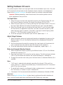
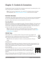
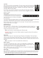
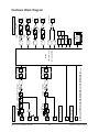
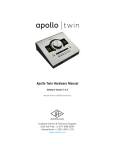
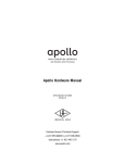
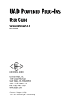
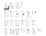
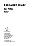
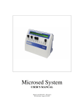
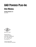
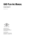
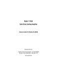
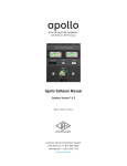
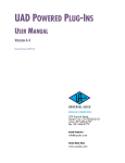
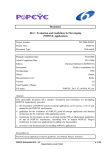
Apollo Twin Hardware Manual
Manual Version 150702
Customer Service & Technical Support:
USA Toll-Free: +1-877-698-2834
International: +1-831-440-1176
www.uaudio.com
A Letter from Bill Putnam Jr.
Thank you for deciding to make the Apollo Twin High-Resolution Interface part of your
music making experience. We know that any new piece of gear requires an investment
of time and money — and our goal is to make your investment pay off. The fact that we
get to play a part in your creative process is what makes our efforts meaningful, and we
thank you for this.
In many ways, Apollo, Apollo 16, and Apollo Twin represent the best examples of what
Universal Audio has stood for over its long history; from UA’s original founding in the
1950s by my father, through our current vision of delivering the best of both analog and
digital audio technologies.
Starting with its high-quality analog I/O, Apollo Twin’s superior sonic performance serves
as its foundation. This is just the beginning however, as Apollo Twin is the only desktop
audio interface that allows you to run UAD plug-ins in real time. Want to monitor yourself
through a Neve® console channel strip while tracking bass through a classic Fairchild or
LA-2A compressor? Or how about tracking vocals through a Studer® tape machine with
some added Lexicon® reverb?* With our growing library of more than 90 UAD plug-ins,
the choices are limitless.
At UA, we are dedicated to the idea that this powerful technology should ultimately serve
the creative process — not be a barrier. These are the very ideals my father embodied as
he invented audio equipment to solve problems in the studio. So as you begin to incorporate Apollo Twin into your creative process, we hope that the excitement and pride
that we’ve built into it comes through. We believe Apollo Twin will earn its way into your
creative workflow by providing stunning fidelity, great ease-of-use, and rock-solid reliability for years to come.
As always, please feel free to reach out to us via our website www.uaudio.com, and via
our social media channels. We look forward to hearing from you, and thank you once
again for choosing Universal Audio.
Sincerely,
Bill Putnam Jr.
*All trademarks are recognized as property of their respective owners.
Individual UAD Powered Plug-Ins sold separately.
Apollo Twin Hardware Manual
ii
Welcome
Table Of Contents
Tip: Click any section or page number
to jump directly to that page.
A Letter from Bill Putnam Jr.................................................................................ii
Chapter 1: Introduction.......................................................................... 4
Welcome to Apollo Twin....................................................................................... 4
Apollo Twin Features........................................................................................... 5
Operational Overview........................................................................................... 7
About Apollo Twin Documentation........................................................................ 9
Web Documentation.......................................................................................... 10
Technical Support............................................................................................. 11
Chapter 2: Quick Start......................................................................... 12
Quick Start Overview......................................................................................... 12
Hardware Setup................................................................................................ 13
Software Setup................................................................................................. 14
Connect to Input Sources and Monitor System..................................................... 14
Setting Hardware I/O Levels............................................................................... 16
Chapter 3: Controls & Connectors.......................................................... 17
Controls Overview............................................................................................. 17
Top Panel......................................................................................................... 19
Front Panel...................................................................................................... 22
Side Panel....................................................................................................... 22
Rear Panel....................................................................................................... 23
Chapter 4: Specifications..................................................................... 25
Specification Tables.......................................................................................... 25
Hardware Block Diagram................................................................................... 29
Chapter 5: Notices............................................................................... 30
Important Safety Information............................................................................. 30
Warranty.......................................................................................................... 31
Maintenance.................................................................................................... 31
Repair Service.................................................................................................. 31
Apollo Twin Hardware Manual
3
Table Of Contents
Chapter 1: Introduction
Welcome to Apollo Twin
High-Resolution Desktop Music Production with Classic Analog Sound
Apollo Twin reinvents desktop recording by delivering legendary analog studio sound, feel, and flow to
music creators everywhere. This 2x6 Thunderbolt
audio interface for Mac combines the same impeccable 24/192 kHz audio conversion of Universal
Audio’s acclaimed Apollo series with onboard Realtime UAD SOLO or DUO Processing. Plus it introduces new Unison™ technology, a breakthrough in
classic mic preamp emulation. Record your music
in real time (at near-zero latency) through the full
range of UAD plug-ins — from Neve, Studer, Manley, Lexicon, API and more* — putting racks of
vintage EQs, compressors, mic preamps, tape machines, reverbs, and guitar amps at your fingertips.
A Universal Audio breakthrough, Apollo Twin’s
Unison technology gives you the tone of the world’s
most sought-after tube and solid state mic preamps
— including their all-important impedance, gain
stage “sweet spots,” and component-level circuit
behaviors. Based on unprecedented hardware-software integration between Apollo’s mic preamps and
its onboard UAD plug-in processing, Unison lets
you record through stunning emulations like the
bundled UA 610-B Tube Preamp plug-in.
LINE OUT
3
MONITOR
L
4
R
OPTICAL IN
POWER
OFF
MIC/LINE 2
MIC/LINE 1
ON 12VDC
Note: For complete Unison details, see the
Apollo Software Manual.
Apollo Twin’s smart feature set includes two class-leading mic/line preamps, two analog
line outputs, two digitally controlled analog monitor outputs for full resolution at all listening levels, and up to eight additional channels of digital input via Optical connection.
Onboard UAD SOLO or DUO Processing lets you use UAD plug-ins both during realtime
tracking and for mixing within Pro Tools, Cubase, Logic, Ableton Live, and more.
With its ergonomic desktop design, rugged aluminum construction, and front panel headphone and instrument connections, Apollo Twin has all the right tools, all in the right
place.
*Apollo Twin includes the “Realtime Analog Classics” UAD plug-in bundle. All other plug-ins are sold separately at
www.uaudio.com. All trademarks are property of their respective owners.
Apollo Twin Hardware Manual
4
Chapter 1: Introduction
Apollo Twin Features
Key Features
• Desktop 2x6 Thunderbolt audio interface with world-class 24-bit/192 kHz audio conversion
• Realtime UAD Processing for tracking through vintage Compressors, EQs, Tape Machines, Mic Preamps, and Guitar Amp plug-ins with near-zero (sub-2ms) latency
• Thunderbolt connection for blazing-fast PCIe speed and rock-solid performance on
modern Macs
• Unison™ technology offers stunning models of classic tube and transformer-based
mic preamps
• Two premium mic/line preamps; Two line outputs; front-panel Hi-Z instrument input
and headphones output
• Two digitally controlled analog monitor outputs for full resolution at all listening levels
• Up to eight channels of additional digital input via Optical connection
• Uncompromising analog design, superior components, and premium build quality
• Runs UAD Powered Plug-Ins via Audio Units, VST, RTAS & AAX64 in all major DAWs
All Features
Audio Interface
• Sample rates up to 192 kHz* at 24-bit word length
• Up to 10 x 6 simultaneous input/output channels
• Two channels of analog-to-digital conversion via:
• Two balanced mic/line inputs
• One Hi-Z instrument input
• Six channels of digital-to-analog conversion via:
• Digitally-controlled stereo monitor outputs
• Stereo headphone outputs
• Line outputs 3-4
• Up to eight channels of digital inputs via:
• Eight channels ADAT optical with S/MUX for high sample rates, or
• Two channels S/PDIF optical with sample rate conversion
Microphone Preamplifiers
• Two high-resolution, ultra-transparent, digitally-controlled analog mic preamps
• Front panel and software control of all preamp parameters
• Low cut filter, 48V phantom power, 20 dB pad, polarity inversion, and stereo linking
*96 kHz maximum on S/PDIF digital inputs
Apollo Twin Hardware Manual
5
Chapter 1: Introduction
Monitoring
•
•
•
•
Digitally-controlled analog monitor outputs maintains highest fidelity
Independently-addressable stereo headphone outputs
Independently-addressable line outputs 3-4 can be used for additional cue mix
Front panel control of monitor levels and muting
UAD-2 Inside
•
•
•
•
•
One (SOLO) or two (DUO) SHARC DSP processors
Realtime UAD Processing on all analog and digital inputs
Same features and functionality as other UAD-2 devices when used with DAW
Includes UAD Powered Plug-Ins “Realtime Analog Classics” bundle
Complete UAD Powered Plug-Ins library is available online
Software
Console application:
•
•
•
•
Enables tracking and/or monitoring with Realtime UAD Processing
Remote control of Apollo Twin features and functionality
Virtual I/O for routing DAW tracks through Console
Two independent stereo Auxiliary busses
Console Recall plug-in:
• Saves Apollo Twin configurations inside DAW sessions for easy recall
• Facilitates control of Apollo Twin monitoring features from within the DAW
• VST, RTAS, AAX 64, and Audio Units plug-in formats
UAD Meter & Control Panel application:
• Configures global UAD settings and monitors system usage
Other
•
•
•
•
Attractive and durable desktop form factor
Locking power supply prevents accidental disconnection
Easy firmware updates
One year warranty includes parts and labor
Package Contents
• Apollo Twin unit
• Power supply with (4) AC connectors
(Changeable AC connectors for USA, Europe, UK, Australia, and China)
• Getting Started URL card
Apollo Twin Hardware Manual
6
Chapter 1: Introduction
Operational Overview
Audio Interface
First and foremost, Apollo Twin is a premium 2x6 Thunderbolt audio interface with
world-class 24-bit/192 kHz audio conversion. Apollo Twin connects to the outputs and
inputs of other audio gear, and performs analog-to-digital (A/D) and digital-to-analog
(D/A) audio conversions on the gear’s signals. The digital audio signals are routed into
and out of the host computer via the high-speed PCIe protocol, which is carried on a
single Thunderbolt cable.
Apollo Twin leverages Universal Audio’s expertise in DSP acceleration, UAD Powered
Plug-Ins, and analog hardware design by integrating the latest cutting edge technologies
in high-performance A/D-D/A conversion, DSP signal reconstruction, and host connectivity. Apollo Twin acts as both an audio interface with integrated DSP effects for tracking
and monitoring as well as a fully integrated UAD-2 DSP accelerator for mixing and mastering.
About Realtime UAD Processing
Apollo Twin has the ability to run UAD Powered Plug-Ins in realtime. Apollo Twin’s
groundbreaking DSP + FPGA technology enable UAD plug-ins to run with latencies in
the sub-2ms range, and multiple plug-ins can be stacked in series without additional
latency.
Realtime UAD Processing facilitates the ultimate sonic experience while monitoring and/
or tracking.
Note: Apollo Twin, like other UAD-2 devices, can only load UAD Powered Plug-Ins,
which are specifically designed to run on UAD-2 DSP accelerators. Native (hostbased) plug-ins cannot run on the UAD-2 DSP.
Console Software
The Console software application runs on the host computer and is used to control Apollo
Twin mixing and monitoring with Realtime UAD Processing, access the audio interface
I/O settings, and more. Console’s analog-style workflow is designed to provide quick access to the most commonly needed features in a familiar, easy-to-use mixer interface.
Realtime UAD Processing is a special function that is available only within Console. All
of Apollo Twin’s analog and digital inputs can perform Realtime UAD processing simultaneously, and Console inputs with (or without) Realtime UAD Processing can be routed
into the DAW for recording.
Console controls Apollo Twin’s digital mixer so you can monitor Apollo Twin’s inputs (with
or without Realtime UAD Processing) without using any other audio software such as a
DAW.
Console is integral to unleashing the power of Apollo Twin. For complete details about
how to use Console and Realtime UAD Processing, refer to the Apollo Software Manual.
Apollo Twin Hardware Manual
7
Chapter 1: Introduction
UAD Powered Plug-Ins in a DAW
Apollo Twin and UAD plug-ins can also be used within a DAW without the use of Console.
UAD plug-ins loaded within the DAW operate like other (non-UAD) plug-ins, except the
processing occurs on the Apollo Twin DSP instead of the host computer’s processor. In
this scenario, UAD plug-ins are subject to the latencies incurred by I/O buffering.
For details about using UAD Powered Plug-Ins in a DAW, see the UAD System Manual.
Standalone Use
Although the Console application is required to utilize all Apollo Twin features, the hardware unit can be used as a digital mixer with limited functionality without a Thunderbolt
connection to a host computer.
All currently active I/O assignments, signal routings, and monitor settings are saved to internal firmware when Apollo Twin is powered down and persist when power is re-applied.
Therefore the last-used settings are always available even when a host computer is not
connected.
Note that UAD plug-in instantiations are not retained on power down, because the plugin files reside on the host computer. However, if UAD plug-ins are active when Apollo
Twin’s connection to the host system is lost (if the Thunderbolt cable is unplugged), the
current UAD plug-in configurations remain active for processing until Apollo Twin is powered down.
Note: Standalone use is unavailable when cascading multiple Apollo units.
Apollo Twin Hardware Manual
8
Chapter 1: Introduction
About Apollo Twin Documentation
Documentation for all Apollo components is extensive, so instructions are separated by
areas of functionality. Each functional area has a separate manual file. An overview of
each file, and how they are accessed, is provided in this section.
Note: Extensive Web Documentation, including technical information not available
in other publications, is also available.
Apollo Manual Files
Note: All manual files are in PDF format. PDF files require a free PDF reader application such as Preview (included with Mac OS X) or Adobe Reader.
Apollo Hardware Manuals
Each Apollo model has a unique hardware manual. The Apollo hardware manuals contain
complete hardware-related details about one specific Apollo model. Included are detailed
descriptions of all hardware features, controls, connectors, and specifications.
Note: Each hardware manual contains the unique Apollo model in the file name.
Apollo Software Manual
The Apollo Software Manual is the companion guide to the Apollo hardware manuals. It
contains detailed information about how to configure and control all Apollo software features for all Apollo models using the Console application, Console Settings window, and
Console Recall plug-in. Refer to the Apollo Software Manual to learn how to operate the
software tools and integrate Apollo’s functionality into the DAW environment.
Note: All Apollo models have the same software manual.
UAD System Manual
The UAD System Manual is the complete operation manual for Apollo’s UAD-2 functionality and applies to the entire UAD-2 product family. It contains detailed information
about installing and configuring UAD devices, the UAD Meter & Control Panel application, buying optional plug-ins at the UA online store, and more. It includes everything
about UAD except Apollo-specific information and individual UAD plug-in descriptions.
UAD Plug-Ins Manual
The features and functionality of all individual UAD Powered Plug-Ins is detailed in the
UAD Plug-Ins Manual. Refer to this document to learn about the operation, controls, and
user interface of each UAD plug-in that is developed by Universal Audio.
Direct Developer Plug-Ins
UAD Powered Plug-Ins includes plug-ins created by our Direct Developer partners. Documentation for these 3rd-party plug-ins are separate files written and provided by the
plug-in developers. The file names for these plug-in manuals are the same as the plug-in
titles.
Apollo Twin Hardware Manual
9
Chapter 1: Introduction
Installed Documentation Location
All documentation is copied to the startup disk during software installation:
• Macintosh HD/Applications/Universal Audio
Accessing Installed Documentation
Any of these methods can be used to access installed documentation:
• Navigate the file system within the Mac OS X Finder
• Choose “Documentation” from the Help menu within the Console application
• Click the “View Documentation” button in the Help panel within the UAD Meter &
Control Panel application
• Manuals are also available online: www.uaudio.com/support/manuals.html
Web Documentation
UA Support Videos
Many informational videos are available online to help you get started with Apollo:
• www.uaudio.com/support/thunderbolt
Apollo Support Page
The latest technical information for Apollo is posted on the Universal Audio website. The
Apollo Thunderbolt support page contains updated, late-breaking information that is not
available in other publications. Please visit this page for the latest news:
• www.uaudio.com/support/thunderbolt
UAD Users Forum
The unofficial UAD users forum, for the exchange of tips and information, is online at:
• www.uadforum.com
Apollo Twin Hardware Manual
10
Chapter 1: Introduction
Technical Support
Universal Audio provides free customer support to all registered Apollo users. Support
specialists are available to assist you via email and telephone during normal business
hours, which are from 9 AM to 5 PM, Monday through Friday, Pacific Standard Time.
Email Support
To request online support via email, click the link below for a direct link to the help
ticket form:
• https://www.uaudio.com/my/support/create/
Alternately, visit the main support page at www.uaudio.com/support, then click the blue
“Submit Support Ticket” button on the right side of the web page to create a help ticket.
Telephone Support
USA toll-free: +1-877-698-2834 (1-877-MY-UAUDIO)
International: +1-831-440-1176
Germany, Austria, Switzerland,
France, Benelux: Apollo Twin Hardware Manual
+31 (0) 20 800 4912
11
Chapter 1: Introduction
Chapter 2: Quick Start
Quick Start Overview
Apollo Twin hardware and software installation and setup consists of these main steps,
which are detailed in this chapter:
1. Hardware Setup: Connect and power the Apollo Twin hardware
2. Software Setup: Download and install the Apollo Twin software
3. Connect to Input Sources and Monitor System
4. Setting Hardware I/O Levels: Learn how to adjust input and output levels
Apollo Twin Hardware Manual
12
Chapter 2: Quick Start
Hardware Setup
Select a Suitable Location
• Locate Apollo Twin on a flat surface so its feet will maintain airflow beneath the unit.
• The location should be sturdy enough to securely hold its weight and withstand
the pressure of operating the top panel controls.
• Leave enough room behind the unit for connected cabling.
• Do not block the cooling vents on the bottom or sides of the unit.
Connect to Computer and Power
Caution: Before powering Apollo Twin, lower the volume of the monitor speakers
(if connected) and remove headphones from your ears.
1. Connect a Thunderbolt cable (not included) between Apollo Twin and the host
computer.
2. Connect the included power supply to an AC outlet (Apollo Twin cannot be bus
powered).
3. Connect the locking power supply to the rear panel of Apollo. Align the two tabs
on the power cable's connector to the notches on the input, then rotate the barrel
to prevent accidental disconnection.
Important: After ensuring the locking barrel tabs are aligned with the chassis slots
and the barrel is fully inserted, rotate the barrel to secure the connector.
4. Apply power to Apollo Twin using the rear panel's power switch.
Apollo Twin is now ready for Software Setup.
Apollo Twin Hardware Manual
13
Chapter 2: Quick Start
Software Setup
Note: Items on this page are detailed in the Apollo Software Manual. See About
Apollo Twin Documentation for related information.
System Requirements
All system requirements must be met for Apollo Twin to operate properly. Before proceeding with installation, see the system requirements in the Apollo Software Manual.
Software Installation
The software must be installed to use the hardware and UAD plug-ins. The UAD Powered
Plug-Ins software installer contains the Apollo Twin software and drivers.
To obtain the latest UAD Powered Plug-Ins software installer, visit:
• www.uaudio.com/downloads
Registration and Authorization
Apollo Twin must be registered and authorized at my.uaudio.com to unlock UAD plug-ins
that are bundled with the product. Registration and authorization via a web browser is
triggered automatically by the UAD software the first time the device is connected.
System Configuration
Complete details about setting up the Apollo Twin system, including how to integrate
with a DAW and related information, are included in the Apollo Software Manual.
Console Application
The included Console application is the software interface for the Apollo Twin hardware.
Console controls Apollo Twin and its digital mixing, monitoring, and Realtime UAD Processing features. Console is also used to configure Apollo Twin’s I/O settings such as
sample rate, clock source, and reference levels.
For complete details about how to operate Console, refer to the Apollo Software Manual.
Apollo Expanded
When more I/O and/or DSP is needed, up to four Apollo interfaces can be cascaded together via Thunderbolt in a multiple-unit configuration. For complete details about multiunit cascading, refer to the Apollo Software Manual.
UA Support Videos
Many informational videos are available online to help you get started with Apollo Twin:
• www.uaudio.com/support/thunderbolt
Apollo Twin Hardware Manual
14
Chapter 2: Quick Start
Connect to Input Sources and Monitor System
One typical Apollo Twin setup is illustrated below. For complete details about all of
Apollo Twin's connectors and controls, see Chapter 3: Controls & Connectors.
Instrument
Headphones
Speaker
System
Microphone
LINE OUT
3
MONITOR
L
4
R
OPTICAL IN
POWER
OFF
MIC/LINE 2
MIC/LINE 1
ON 12VDC
Typical Apollo Twin setup connections
Apollo Twin Hardware Manual
15
Chapter 2: Quick Start
Setting Hardware I/O Levels
This section explains how to set input gain levels for the hardware inputs (mic, line, and
Hi-Z) and adjust volume levels for the hardware outputs (monitors and headphones).
Refer to the top panel illustration for control names and numbers mentioned below.
Important: Before proceeding, lower the volume of the monitor speakers and remove headphones from your ears.
Set Input Gains
1. Select the input channel to be adjusted by pressing the Preamp button (9) until
the Channel Selection Indicator (3) displays the channel (CH1 or CH2).
2. Select the input type (mic or line) by pressing the Input Select button (11a) until
the Input Type indicator (5) displays the desired input jack* (see note below).
3. Adjust the channel's gain by increasing the Level knob (1) until the input meter
for the channel (4) approaches maximum, but does not reach the red clip LED
when the input signal is present. If the level is too high to avoid clipping (when
the red “C” LED illuminates), enable the pad (11).
4. To set the input gain for the other input channel, repeat steps 1 – 3.
Adjust Output Volumes
1. Select the output volume to be adjusted (monitor or headphone) by pressing the
Monitor button (10) until the Monitor Selected (6) or Headphone Selected (8)
indicator is lit.
2. Set the volume level by carefully increasing the Level knob until the desired volume is reached (you may need to adjust the volume of the speakers).
3. To set the other output volume (monitor or headphone), repeat steps 1 – 2.
Mute (and Unmute) Monitor Outputs
1. Select the Monitor outputs by pressing the Monitor button (10) until the Monitor
Selected (6) indicator is lit.
2. Press the Level knob (1) to mute the monitor outputs. The Volume Level Indicator
LEDs (2) are red when the monitors are muted and Monitor is selected (6).
3. To toggle the monitor mute state, press the Level knob (1) whenever Monitor (6) is
selected.
Notes:
• *Hi-Z input is automatically selected, overriding the channel 1 Mic and Line
inputs, when a ¼” mono TS (tip-sleeve) plug is connected to the Hi-Z Instrument
jack (12) on the front panel.
• To control both channels simultaneously when a stereo source is connected, press
the Link button (11) when an input is selected (9).
• Line outputs 3 & 4 are accessed and controlled via software only (Console or DAW).
What Next?
Refer to the Apollo Software Manual to learn how to configure the audio interface settings, use the Console application and Realtime UAD Processing, and more.
Apollo Twin Hardware Manual
16
Chapter 2: Quick Start
Chapter 3: Controls & Connectors
Complete details about the Apollo Twin hardware controls and all connector jacks on the
front and rear panels are provided in this chapter.
Note: To set input gain levels (mic, line, and Hi-Z) and output volumes (monitors
and headphones), see Setting Hardware I/O Levels in the Quick Start chapter.
Controls Overview
Some Apollo Twin controls have multiple functions. The function of each control depends
on the current operating mode and the current settings within that mode. To control a
particular setting, the control must be activated for the function.
Operating Modes
Apollo Twin’s top panel has two operating modes: Preamp and Monitor. The function and
availability of the top panel controls vary depending on the active operating mode. The
active mode is selected with the PREAMP and MONITOR buttons. Press the button to
activate the mode. Each mode is explained in greater detail below.
Note: All top panel functions can be operated concurrently (without switching
modes) from within the companion Console software application. See the Apollo
Software Manual for details.
PREAMP Mode
When Apollo Twin is in Preamp mode, all top panel controls are related to the
input functions only. To adjust any input function, press the PREAMP button to
enter Preamp mode and activate the input channel controls.
Note: Monitor and headphone functions cannot be performed in Preamp
mode.
Preamp Channels
Apollo Twin has two analog input channels and one set of input channel controls. The
channel controls adjust all channel functions for the currently selected channel. After
switching the selected channel, the other channel can be adjusted.
Channel Selection
The currently selected channel is shown by the CH1 and CH2 indicators
at the upper left of the main display panel, above the input meters. The
top panel controls only adjust the functions for the currently selected
channel.
When in Preamp mode, press the PREAMP button or the LEVEL knob to
change the selected channel. Press again to switch back to the other channel.
Apollo Twin Hardware Manual
17
Chapter 3: Controls & Connectors
OPTICAL IN
LINE
Input Type
Each input channel has one preamplifier. The input source used by the preamp can
be the mic input or the line input. The input source is determined by the pressing
the INPUT button when the channel is selected. The input type is shown by the
indicators below the input meters.
On channel 1 only, the Hi-Z instrument can be used as the input type. The Hi-Z
input is selected automatically when an instrument cable is plugged into the front
panel Hi-Z input.
Preamp Options
The two input channels each have a set of various preamp options that can be activated for the
input withe the row of six buttons at the bottom
of the top panel.
The current state of the preamp options are indicated in the display panel above the preamp option buttons. Available options are dim when inactive and bright when enabled.
Not all preamp options are available with all input types. For specific details, see the Top Panel
Controls section later in this chapter.
MONITOR Mode
When Apollo Twin is in Monitor mode, all top panel controls are related to output functions only. To adjust any output function, press the MONITOR button to enter Monitor
mode and activate the monitor controls.
Note: Input functions cannot be performed in Monitor mode.
Important: Apollo Twin must be in Monitor mode to change the volume of the monitor or
headphone outputs.
Output Types
LINE OUT
3
MONITOR
L
MIC/LINE 2
Apollo Twin has two main* stereo OPTICAL
outputINtypes: Monitor and Headphone. The Level knob
is
used to set the volume level for both output types. The Level knob adjusts the volume for the
currently selected output. After switching the selected output, the other output volume can be
adjusted.
4
R OPTICAL IN
POWER
Note: *Line outputs 3 and 4 are controlled with software only.
Monitor Selection
OFFis shown
ON 12VDC
The currently selected output type
by the MONITOR and HEADPHONEPOWER
indicators at the right of the main display, above and below the output meters. The
Level knob adjusts volume for the currently selected output.
OFF
When in Monitor mode, press the MONITOR button to change the selected output.
LINE OUT
MONITOR
Press again to switch to the other output.
3
L
MIC/LINE 2
Monitor Mute
OPTICAL IN
ON 12VDC
MIC/LINE 1
When MONITOR is selected, press the Level knob to mute (silence) the stereo monitor outputs.
The green Level indicators (the ring of LEDs around the4 knob) are RRED when the monitor outPOWER
puts are muted. Press again
to unmute the monitor outputs.
Apollo Twin Hardware Manual
OFF
18
ON 12VDC
Chapter 3: Controls & Connectors
MIC/LINE
LIN
Top Panel
Refer to the illustration below for control descriptions in this section.
1
2
3
4
5
6
7
8
9
10
11
Apollo Twin’s top panel elements
(1) Level Knob & Switch
The Level knob & switch controls multiple functions. The knob’s current function is selected with the Preamp (9) and Monitor (10) buttons.
Rotate clockwise to increase level of the selected function. When Monitor is selected (6),
press to mute/unmute the monitor outputs. When Preamp is selected (3), press to alternate between channels 1 & 2.
Unison Integration: The Level knob can also be used to control Unison-enabled
UAD preamp plug-ins. See the Apollo Software Manual for complete Unison details.
(2) Preamp Gain & Volume Level Indicator LEDs
The LEDs around the Level knob indicate the relative level of the selected function (input preamp gain or monitor/headphone volume).
Note: The indicator LEDs are red when Monitor (10) is selected and the monitor
outputs are muted.
Apollo Twin Hardware Manual
19
Chapter 3: Controls & Connectors
(3) Channel Selection Indicators
The currently selected input channel is indicated by the lit channel name above its input
meter (CH1 or CH2). Press the Preamp button (9) to switch between channels 1 & 2.
Tip: You can also switch between channels 1 & 2 by pressing the Level knob (1),
but only when in Preamp Mode (when the input controls are active).
(4) Input Meters
These meters display the incoming signal level for input channels 1 & 2. Reduce the
channel’s preamp gain (see Setting Levels) if its red clip LED illuminates.
(5) Input Type Indicators
These indicators show which input type (mic, line, or Hi-Z) is active for the selected
channel. Use the Input Select button (11a) to change the input type.
Note: Hi-Z input is available for channel 1 only.
(6) Monitor Selected Indicator
When lit, the Level knob (1) controls volume and muting of the monitor outputs (15).
Press the Monitor button (10) to activate the monitor controls.
(7) Stereo Output Meters
These meters display the main stereo signal output levels.* Main output levels are independent of monitor and headphone volume levels. Reduce levels feeding the output(s) if
a red “C” (clip) LED at the top of the Output Meters illuminates.
*Exception: If HEADPHONES is currently selected on Apollo Twin and the Headphone Source in Console is set to HP, these output meters indicate the level being
sent to the headphone bus via Console’s headphone sends and/or the DAW.
(8) Headphone Selected Indicator
When lit, the Level knob (1) controls the volume of the headphones output (13). Press
the Monitor button (9) to activate the headphones controls (you may need to push it
twice).
(9) Preamp Button
Press PREAMP to activate the input channel controls. Press again to alternate between
channels 1 & 2.
Tip: You can also switch between channels 1 & 2 by pressing the Level knob (1),
but only when in Preamp Mode (when the input controls are active).
(10) Monitor Button
Press MONITOR to activate the control of volume levels with the Level knob (1). Press
again to alternate between control of the monitor and headphone volumes.
Tip: Indicators (6) and (8) determine which volume (monitor or headphone) is being controlled with the Level knob (1).
Apollo Twin Hardware Manual
20
Chapter 3: Controls & Connectors
(11) Preamp Option Buttons
These six buttons control the preamp options (a – f below) when the input channel is
selected (3). The preamp option is active when its indicator is lit. When Monitor (6) or
Headphone (8) is selected, the preamp options cannot be modified and this portion of
the display is unlit.
Unison Integration: The Preamp Options can also be used to control Unison-enabled UAD preamp plug-ins. See the Apollo Software Manual for complete Unison
details.
Refer to the illustration below for control descriptions in this section.
a
b
c
d
e
f
Apollo Twin’s preamp option buttons
(a) Input Select
Selects the active input jack for the channel. Press to alternate between the mic & line
inputs. The current selection is displayed by the input type indicators (5).
The Hi-Z input is selected automatically whenever a ¼” mono (tip-sleeve) plug is connected to the front panel’s Hi-Z Instrument jack (12).
Note: Hi-Z input is available for channel 1 only.
(b) Low Cut Filter
Enables a low cut (high pass) rumble filter with a cutoff frequency of 75 Hz.
(c) +48V
Enables 48-volt phantom power for the mic input. Phantom power is typically needed for
condenser microphones. +48 is available for the microphone inputs only.
Caution: To avoid potential equipment damage, disable +48V phantom power on
the channel before connecting or disconnecting its XLR input.
(d) Pad
Attenuates (lowers) the input signal level by 20 dB. Pad is unavailable for the line inputs
and the Hi-Z instrument input.
(e) Polarity Ø
Inverts the polarity (aka “phase”) of the input signal.
(f) Link
Links inputs 1 & 2 so both channels are adjusted simultaneously as a stereo pair.
Note: Link cannot be activated when a plug is inserted in the Hi-Z jack (12).
Apollo Twin Hardware Manual
21
Chapter 3: Controls & Connectors
Front Panel
Refer to the illustration below for control descriptions in this section.
12
13
Apollo Twin’s front panel elements
(12) Hi-Z Instrument Input
Connect any guitar, bass, or other high impedance instrument here. This jack automatically overrides the channel 1 mic and line inputs.
Levels for the Hi-Z input are set using the same method as the mic and line inputs.
Note: This jack accepts a ¼” mono (tip-sleeve) plug only.
(13) Headphone Output
Connect ¼” stereo headphones here. Volume is set with the Level knob (1) when Headphone (8) is selected with the Monitor button (10).
Side Panel
Kensington Security Slot (not shown)
The anti-theft security slot on the side panel connects to any standard Kensington lock.
Apollo Twin Hardware Manual
22
Chapter 3: Controls & Connectors
Rear Panel
Refer to the illustration below for control descriptions in this section.
Note: All rear panel ¼” jacks can accept unbalanced TS (tip-sleeve) or balanced
TRS (tip-ring-sleeve) connections.
20
19
18
LINE OUT
3
MONITOR
L
4
R
OPTICAL IN
POWER
OFF
MIC/LINE 2
MIC/LINE 1
ON 12VDC
17
16
15
14
Apollo Twin’s rear panel elements
(14) Mic/Line Inputs 1 & 2
The jacks for channels 1 & 2 accept either a male XLR plug for connecting to the mic
input, or a ¼” phone plug for connecting to the line input.
The input that is used for the channel (mic or line) is specified with the Input Type button (11a).
Caution: To avoid potential equipment damage, disable +48V phantom power on
the channel before connecting or disconnecting its XLR input.
(15) Monitor Outputs
Connect the powered monitor speakers (or speaker amplifiers) here. Volume is set with
the Level knob (1) when Monitor is selected (6) with the Monitor button (10).
(16) Line Outputs 3 & 4
These ¼” phone outputs are accessed via software (Console or DAW). Line outputs 3 & 4
are used to send audio to other equipment.
(17) Power Supply Input
The included power supply must be connected here (Apollo Twin cannot be bus powered). Rotate locking connector to prevent accidental disconnection.
Important: After ensuring the locking barrel tabs are aligned with the chassis slots
and the barrel is fully inserted, rotate the barrel to secure the connector to the
chassis.
Apollo Twin Hardware Manual
23
Chapter 3: Controls & Connectors
(18) Power Switch
This rocker switch applies power to Apollo Twin. Switch to OFF when not in use.
Caution: Before powering Apollo Twin, lower the volume of the monitor speakers
and remove headphones from your ears.
(19) Optical In
This is a TOSLINK input for connection to other gear with an optical ADAT or S/PDIF
output.
Note: The protocol to be used (ADAT or S/PDIF) is specified in the Interface panel
of the Console Settings window.
(20) Thunderbolt Port
Connect the Thunderbolt cable (not included) here. A Thunderbolt connection to the host
computer is required to use all Apollo Twin features and UAD Powered Plug-Ins.
Note: Apollo Twin may be connected to a Thunderbolt 1 or Thunderbolt 2 port.
Apollo Twin Hardware Manual
24
Chapter 3: Controls & Connectors
Chapter 4: Specifications
Specification Tables
All audio specifications are typical performance unless otherwise noted, tested under the
following conditions: 48 kHz internal sample rate, 24-bit sample depth, 20 kHz measurement bandwidth, with balanced inputs and outputs.
SYSTEM
I/O Complement
Microphone Inputs
Two
Analog Line Inputs
Two
Hi-Z Instrument Inputs
One
Analog Line Outputs
Two
Analog Monitor Outputs
Two (one stereo pair)
Headphone Outputs
One stereo
Digital Input Port (TOSLINK optical)
One (ADAT or S/PDIF, selectable)
Thunderbolt Port
One (Thunderbolt 2 compatible)
A/D – D/A Conversion
Supported Sample Rates (kHz)
44.1, 48, 88.2, 96, 176.4, 192
Bit Depth Per Sample
24
Simultaneous A/D conversion
Two channels
Simultaneous D/A conversion
Six channels
Analog Round-Trip Latency
1.1 milliseconds @ 96 kHz sample rate
Analog Round-Trip Latency with up to four serial
UAD Powered Plug-Ins via Console application
1.1 milliseconds @ 96 kHz sample rate
(continued)
Apollo Twin Hardware Manual
25
Chapter 4: Specifications
ANALOG I/O
Line Inputs 1 & 2
Jack Type (combo mic/line balanced inputs)
Female ¼” TRS Balanced
Dynamic Range (A–weighting)
117.5 dB
Signal-to-Noise Ratio (A–weighting)
117.5 dB
Total Harmonic Distortion + Noise
–108 dBFS
Common-Mode Rejection Ratio (CMRR)
Greater than 60 dB (10’ cable)
Frequency Response
20 Hz – 20 kHz, ±0.1 dB
Input Impedance
10K Ohms
Gain Range
+10 dB to +65 dB
Maximum Input Level (@ Minimum Gain)
18 dBV
Maximum Input Level (@ Maximum Gain)
Stereo Level Balance
–37 dBV
±0.05 dB
Microphone Inputs 1 & 2
Jack Type (combo mic/line balanced inputs)
Female XLR Balanced (pin 2 positive)
Phantom Power (switchable per input)
+48V
Dynamic Range (A–weighting)
118 dB
Signal-to-Noise Ratio (A–weighting)
118 dB
Total Harmonic Distortion + Noise
–110 dBFS
Equivalent Input Noise
–127 dB
Frequency Response
20 Hz – 20 kHz, ±0.1 dB
Common-Mode Rejection Ratio (CMRR)
Greater than 70 dB (10’ cable)
Default Input Impedance
5.4K Ohms (variable via Unison preamp model)
Gain Range
+10 dB to +65 dB
Pad Attenuation (switchable per input)
20 dB (variable via Unison preamp model)
Maximum Input Level (@ Minimum Gain, with Pad) 23.8 dBV
Maximum Input Level (@ Maximum Gain, with Pad) –31.2 dBV
Hi-Z Input
Jack Type
Female ¼” TS Unbalanced
Dynamic Range (A–weighting)
117 dB
Signal-to-Noise Ratio (A–weighting)
117 dB
Total Harmonic Distortion + Noise
–101 dBFS
Frequency Response
20 Hz – 20 kHz, ±0.1 dB
Input Impedance
1M Ohms
Maximum Input Level (@ Minimum Gain)
10 dBV
Maximum Input Level (@ Maximum Gain)
–45 dBV
(continued)
Apollo Twin Hardware Manual
26
Chapter 4: Specifications
ANALOG I/O
Line Outputs 3 & 4
Jack Type
¼” Female TRS Balanced
Dynamic Range (A–weighting)
118 dB
Signal-to-Noise Ratio (A–weighting)
118 dB
Total Harmonic Distortion + Noise
–107 dBFS
Frequency Response
20 Hz – 20 kHz, ±0.1 dB
Stereo Level Balance
±0.05 dB
Channel Separation
Greater than 120 dB
Output Impedance
600 Ohms
Maximum Output Level
18 dBV
Monitor Outputs 1 & 2
Jack Type
¼” Female TRS Balanced
Frequency Response
20 Hz – 20 kHz, ±0.1 dB
Dynamic Range (A–weighting)
115 dB
Signal-to-Noise Ratio (A–weighting)
115 dB
Total Harmonic Distortion + Noise
–105 dBFS
Channel Separation
Greater than 118 dB
Stereo Level Balance
±0.05 dB
Output Impedance
600 Ohms
Output Gain Range
–96 dB to 0 dB
Maximum Output Level
18 dBV
Operating Reference Level
+14 dBu, +20 dBu (selectable)
Stereo Headphones Output
Jack Type
¼” Female TRS Stereo (unbalanced)
Frequency Response
20 Hz – 20 kHz, ±0.1 dB
Dynamic Range (A–weighting)
113 dB
Signal-to-Noise Ratio (A–weighting)
113 dB
Channel Separation
Greater than 110 dB
Total Harmonic Distortion + Noise
–101 dBFS
Stereo Level Balance
±0.11 dB
Maximum Output Power
80 milliwatts into 600 Ohms
(continued)
Apollo Twin Hardware Manual
27
Chapter 4: Specifications
DIGITAL INPUTS
S/PDIF
Connector Type
Optical TOSLINK JIS F05 (shared with ADAT)
Format
IEC958
Supported Sample Rates (kHz)
44.1, 48, 88.2, 96
S/PDIF Input Channels
Two (Stereo L/R)
ADAT
Connector Type
Optical TOSLINK JIS F05 (shared with S/PDIF)
Format
ADAT Digital Lightpipe with S/MUX
Supported Sample Rates (kHz)
44.1, 48, 88.2, 96, 176.4, 192
ADAT Input Channels @ 44.1 kHz, 48 kHz
1–8
ADAT Input Channels @ 88.2 kHz, 96 kHz
1 – 4 (S/MUX)
ADAT Input Channels @ 176.4 kHz, 192 kHz
1 – 2 (S/MUX)
Clock Synchronization Sources
Internal, S/PDIF, ADAT (digital clock sync source conditional per selected digital input type)
ELECTRICAL
Power Supply
External AC to DC
AC Connector Type
Changeable blades (UL, VDE, UK, SSA, CCC)
AC Requirements
100V – 240V AC, 50 – 60 Hz
DC Connector Type
Male plug, 2.1 mm x 5.5 mm, center positive
DC Requirements
12 VDC, ±5%
Maximum Power Consumption
12 Watts
ENVIRONMENTAL
Operating Temperature Range
32º to 95º Fahrenheit (0º to 35º Celsius)
Storage Temperature Range
–40º to 176º Fahrenheit (–40° to 80º Celsius)
Operating Humidity Range
20% to 80%
MECHANICAL
Dimensions
Width
6.31”
Height
2.60”
Depth, Chassis Only
5.86”
Depth, Including Knob & Jack Protrusions
6.20”
Shipping Box (Length x Width x Height)
8” x 8” x 5.5” (20.32cm x 20.32cm x 13.97cm)
Weight
Shipping Weight (with box & accessories)
3.85 pounds
Weight (bare unit)
2.35 pounds
Package Contents
Apollo Twin Unit (SOLO or DUO)
External Power Supply with (4) changeable AC connectors supporting USA, Europe, UK, Australia, China
Getting Started URL Card
Apollo Twin Hardware Manual
28
Chapter 4: Specifications
Apollo Twin Hardware Manual
29
PAD
MIC/LINE
SELECT
INPUT GAIN
10 – 65 dB
HI-Z/MIC HI-Z/MIC-LINE INPUT GAIN
10 – 65 dB
SELECT
SELECT
A/D
A/D
DSP
ø
LOW-CUT POLARITY
ON/OFF CONTROL
DSP
ø
LOW-CUT POLARITY
ON/OFF CONTROL
APOLLO TWIN HARDWARE BLOCK DIAGRAM V06
THUNDERBOLT TM
HOST INTERFACE
OPTO
OPTICAL INPUT
1/4” TRS
LINE IN 2
1M
PAD
+48V
+48V ON/OFF
MIC PAD
IN/OUT
XLR FEMALE
MIC IN 2
1/4” TRS
LINE IN 1
1/4”
HI-Z IN
XLR FEMALE
MIC IN 1
+48V
+48V ON/OFF
MIC PAD
IN/OUT
ANALOG INPUTS
SYSTEM CONTROL
CLOCKING / SYNC
MIXER
PAD
PAD
OUTPUT
VOLUME
PAD
PAD
DRAM
DRAM
+4dBu / -10dBV
SELECT
1/4” TRS
LINE OUT 4
1/4” TRS
LINE OUT 3
1/4” TRS
MON OUT R
1/4” TRS
MON OUT L
1/4” TRS
HEADPHONES OUT
+14dBu / +20dBu
SELECT
+14dBu / +20dBu
SELECT
+4dBu / -10dBV
SELECT
FRONT PANEL
EEPROM
ARM®
PROCESSOR
SHARC®
DSP
SHARC®
DSP
D/A
D/A
D/A
D/A
D/A
D/A
OUTPUT
VOLUME
ANALOG OUTPUTS
Hardware Block Diagram
Chapter 4: Specifications
Chapter 5: Notices
Important Safety Information
Before using this unit, be sure to carefully read the applicable items of these operating
instructions and the safety suggestions. Afterwards, keep them handy for future reference. Take special care to follow the warnings indicated on the unit, as well as in the
operating instructions.
Water and Moisture – Do not use the unit near any source of water or in excessively moist
environments.
Object and Liquid Entry – Care should be taken so that objects do not fall, and liquids
are not spilled, into the enclosure through openings.
Ventilation – When installing the unit in a rack or any other location, be sure there is adequate ventilation. Improper ventilation will cause overheating, and can damage the unit.
Heat – The unit should be situated away from heat sources, or other equipment that produces excessive heat.
Power Sources – The unit should be connected to a power supply only of the type described in the operating instructions, or as marked on the unit.
Power Cord Protection – AC power supply cords should be routed so that they are not
likely to be walked on or pinched by items placed upon or against them. Pay particular
attention to cords at plugs, convenience receptacles, and the point where they exit from
the unit. Never take hold of the plug or cord if your hand is wet. Always grasp the plug
body when connecting or disconnecting it.
Cleaning – Follow these general rules when cleaning the outside of the unit:
a. Turn the power off and unplug the unit
b. Gently wipe with a clean lint-free cloth
c. Do not use aerosol sprays, solvents, or abrasives
Nonuse Periods – The AC power supply cord of the unit should be unplugged from the
AC outlet when left unused for a long period of time.
Damage Requiring Service – The unit should be serviced by a qualified service personnel
when:
a. The AC power supply unit has been damaged; or
b. Objects have fallen or liquid has been spilled into the unit; or
c. The unit has been exposed to rain; or
d. The unit does not operate normally or exhibits a marked change in performance; or
e. The unit has been dropped, or the enclosure damaged.
Servicing – The user should not attempt to service the unit beyond that described in the
operating instructions. All other servicing should be referred to qualified service personnel.
Apollo Twin Hardware Manual
30
Chapter 5: Notices
Warranty
Universal Audio provides a warranty on all hardware products. To learn more, please visit
www.uaudio.com/support/warranty.html or contact Technical Support. This limited warranty gives you specific legal rights. You may also have other rights which vary by state or
country.
Maintenance
Apollo 8 does not contain a fuse or any other user-replaceable parts. The unit is internally calibrated at the factory. No internal user adjustments are available.
Repair Service
If you are having trouble with Apollo 8, the first check all system setups, connections,
software installations, and the Troubleshooting chart. If that doesn’t help, contact Technical Support. To learn more about repair service, please visit:
• www.uaudio.com/support/rma-faq.html
FCC Compliance
Federal Communications Commission
United States Class B Manual Statement
NOTE: This equipment has been tested and found to comply with the limits for a Class B
digital device pursuant to Part 15 of the FCC Rules. These limits are designed to provide reasonable protection against harmful interference in a residential installation. This
equipment generates, uses, and can radiate radio frequency energy and, if not installed
and used in accordance with the instructions, may cause harmful interference to radio
communications. However, there is no guarantee that interference will not occur in a
particular installation. If this equipment does cause harmful interference to radio or
television reception, which can be determined by turning the equipment off and on, the
user is encouraged to try and correct the interference by one or more of the following
measures: -Reorient or relocate the receiving antenna.
• Increase the separation between the equipment and the receiver.
• Connect the equipment into an outlet on a circuit different from that to which the
receiver is connected.
• Consult the dealer or an experienced radio/TV technician for help.
Apollo Twin Hardware Manual
31
Chapter 5: Notices
Disclaimer
The information contained in this manual is subject to change without notice. Universal Audio, Inc. makes no warranties of any kind with regard to this manual, including,
but not limited to, the implied warranties of merchantability and fitness for a particular
purpose. Universal Audio, Inc. shall not be liable for errors contained herein or direct,
indirect, special, incidental, or consequential damages in connection with the furnishing,
performance, or use of this material.
End User License Agreement
Your rights to the Software are governed by the accompanying End User License Agreement, a copy of which can be found at: www.uaudio.com/eula
Trademarks
Universal Audio, the Universal Audio “diamond” logo, Apollo, Apollo Twin, Apollo 16,
Unison technology, UAD, UAD Series, UAD-1, UAD-2, UAD-2 Satellite, Powered PlugIns, 1176LN, 1176SE, Teletronix, LA-2A, LA-3A, LA-610, LA-610MkII, 2-1176, 2-610,
6176, 710 Twin-Finity, 2192, 4-710d, Cambridge EQ, DreamVerb, Plate 140, Precision
Limiter, RealVerb Pro, Precision Buss Compressor, Precision De-Esser, Precision Maximizer, and “Analog Ears | Digital Minds,” are among the trademarks, trade names, and
service marks owned by UA that may appear on the Site, many of which are registered in
the United States and other countries. This is not a comprehensive list of all UA trademarks. All UA trademarks inure to the benefit of UA. Other trademarks and trade names
that may appear on the Site and which are not owned by UA are owned by the respective
owners.
Copyright
Copyright ©2015 Universal Audio, Inc. All rights reserved.
This manual and any associated software, artwork, product designs, and design concepts
are subject to copyright protection. No part of this document may be reproduced, in any
form, without prior written permission of Universal Audio, Inc.
Apollo Twin Hardware Manual
32
Chapter 5: Notices
Universal Audio, Inc.
4585 Scotts Valley Drive
Scotts Valley, CA 95066 USA
Customer Service & Technical Support:
USA Toll-Free: +1-877-698-2834
International: +1-831-440-1176
www.uaudio.com