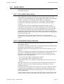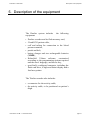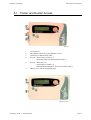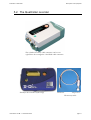
1
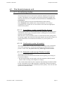
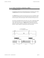
Duolter Access
Triolter
& Quattrolter
User Manual
English
NOVACOR S.A.
4 passage Saint-Antoine
92508 Rueil-Malmaison Cedex - France
Duolter Manual ©1996/2003 NOVACOR S.A. - All rights reserved.
User Manuel 12 GB – 17 December 2003
page 1
User Manuel 12 GB – 17 December 2003
page 2
DUOLTER - TRIOLTER
Contents
1.
INDEX......................................................................................................................... 4
2.
INTRODUCTION...................................................................................................... 7
3.
GUARANTEE ............................................................................................................ 9
4.
HOW THE RECORDER WORKS........................................................................ 11
5.
DESCRIPTION OF THE EQUIPMENT .............................................................. 15
6.
PREPARING FOR THE PROCEDURE............................................................... 21
7.
RECORDING........................................................................................................... 43
8.
READING THE RECORDINGS ........................................................................... 51
9.
MAINTENANCE..................................................................................................... 53
Most information given in this manual applies as well to the
previous devices of the same range, Duolter and Duolter II,
reminding that these devices do not comprise neither position
sensor nor activity sensor.
User Manuel 12 GB – 17 December 2003
page 3
DUOLTER - TRIOLTER
Contents
1. Index
1.
INDEX......................................................................................................................... 4
2.
INTRODUCTION...................................................................................................... 7
3.
GUARANTEE ............................................................................................................ 9
3.1.
3.2.
3.3.
3.4.
3.5.
3.6.
4.
SPECIFIC GUARANTEES CONCERNING UNITS ....................................................... 10
ACCESSORIES ..................................................................................................... 10
RESTRICTIONS OF THE GUARANTEE .................................................................... 10
RESPONSIBILITIES .............................................................................................. 10
UPGRADES ......................................................................................................... 10
COPYRIGHTS ...................................................................................................... 10
HOW THE RECORDER WORKS........................................................................ 11
4.1.
THE BLOOD PRESSURE UNIT................................................................................ 12
4.1.1.
Functioning modes ................................................................................... 12
4.1.1.1.
4.1.1.2.
4.1.1.3.
Auscultatory mode (except Duolter Access)................................................... 12
Oscillometric mode (all models) ...................................................................... 12
Automatic mode (except Duolter Access)........................................................ 12
4.1.2.
Index of arterial compliance (QKd) ......................................................... 13
4.2.
HOLTER ECG..................................................................................................... 14
4.2.1.
The Holter Recording ............................................................................... 14
4.2.2.
HolterSoft Ultima software....................................................................... 14
5.
DESCRIPTION OF THE EQUIPMENT .............................................................. 15
5.1.
TRIOLTER AND DUOLTER ACCESS ...................................................................... 16
5.2.
THE QUATTROLTER RECORDER .......................................................................... 17
5.3.
DISTINGUISH THE DIFFERENT MODELS................................................................ 18
5.3.1.
Duolter Access.......................................................................................... 18
5.3.2.
Triolter...................................................................................................... 18
5.3.3.
Quattrolter................................................................................................ 18
5.4.
THE BATTERY CHARGER ..................................................................................... 19
5.5.
THE CUFF SYSTEM .............................................................................................. 20
5.6.
THE 5 WIRE ECG CABLE .................................................................................... 20
6.
PREPARING FOR THE PROCEDURE............................................................... 21
6.1.
CHARGING THE BATTERY ................................................................................... 22
6.1.1.
The battery charger .................................................................................. 22
6.1.2.
The battery................................................................................................ 24
6.1.3.
Charging the battery................................................................................. 24
6.1.4.
End of charge ........................................................................................... 25
6.2.
INSERTING THE BATTERY INTO THE RECORDER .................................................. 26
6.2.1.
Insertion.................................................................................................... 26
6.2.2.
Test of Safeguard battery (non-rechargeable lithium) ............ 27
6.3.
PROGRAMMING THE UNIT ................................................................................... 27
6.4.
SETTING THE TIME (MANUALLY) ........................................................................ 28
6.4.1.
Programming the time.............................................................................. 29
6.4.2.
Programming the date.............................................................................. 30
6.5.
INSERTING THE FLASH MEMORY CARD ............................................................... 31
User Manuel 12 GB – 17 December 2003
page 4
DUOLTER - TRIOLTER
Contents
6.6.
PLACING THE UNIT ON THE PATIENT ................................................................... 32
6.6.1.
Placing the cuff on the patient.................................................................. 32
6.6.1.1.
6.6.1.2.
6.6.1.3.
6.6.1.4.
6.6.1.5.
6.6.2.
6.6.2.1.
6.6.2.2.
6.6.3.
6.6.3.1.
6.6.3.2.
6.6.3.3.
6.6.3.4.
6.6.3.5.
6.6.3.6.
6.6.4.
7.
Auscultatory or automatic mode ...................................................................... 32
Oscillometric mode .......................................................................................... 33
Recommendations for positioning the cuff ...................................................... 33
Changing arms ................................................................................................. 34
Single-use cuff protector .................................................................................. 35
Placing the ECG electrodes on the patient............................................... 36
Preparation ....................................................................................................... 36
positioning of the electrodes ............................................................................ 37
Placing the recorder on the patient.......................................................... 38
Connecting the ECG cable ............................................................................... 38
Disconnecting the ECG cable .......................................................................... 39
Quattrolter Activity cable................................................................................. 39
Connecting the cuff.......................................................................................... 40
Disconnecting the cuff ..................................................................................... 40
End of placing the unit on the patient .............................................................. 41
The position sensor................................................................................... 42
RECORDING........................................................................................................... 43
7.1.
START-UP ........................................................................................................... 43
7.1.1.
ECG test channels .................................................................................... 44
7.1.1.1.
7.1.1.2.
Systematic acoustical test................................................................................. 44
ECG start-up test display ................................................................................. 44
7.1.2.
ABPM test measurements ......................................................................... 45
7.2.
RECORDING ........................................................................................................ 47
7.2.1.
Recording display..................................................................................... 47
7.2.2.
Weak battery............................................................................................. 47
7.2.3.
Event marker ............................................................................................ 47
7.3.
ABPM RECORDING ............................................................................................ 48
7.3.1.
Manually activated measurements ........................................................... 48
7.3.2.
Palliative measurements........................................................................... 48
7.3.3.
“Suspend” mode....................................................................................... 48
7.3.4.
Unmemorized measurements.................................................................... 49
7.3.5.
Display of measurements.......................................................................... 49
7.3.6.
Stopping blood pressure measurements ................................................... 49
7.3.7.
Display codes ........................................................................................... 50
8.
READING THE RECORDINGS ........................................................................... 51
8.1.
STOPPING RECORDING ........................................................................................ 51
8.1.1.
ABPM manual stop................................................................................... 51
8.1.2.
Automatic stop .......................................................................................... 51
8.2.
TRANSFER TO THE COMPUTER ............................................................................ 51
9.
MAINTENANCE..................................................................................................... 53
9.1.
9.2.
9.3.
9.4.
9.5.
9.6.
9.7.
9.8.
9.9.
9.10.
9.11.
9.12.
9.13.
HANDLING THE RECORDER ................................................................................. 53
CLEANING THE EQUIPMENT ................................................................................ 53
REPAIRS ............................................................................................................. 53
CALIBRATION TEST ............................................................................................ 54
REPLACING THE SAFEGUARD BATTERY .............................................................. 55
STORAGE AND DISPATCH .................................................................................... 55
PREVENTIVE MAINTENANCE ............................................................................... 55
ELECTRICAL SAFETY STANDARDS ...................................................................... 56
PRECAUTIONS IN USE.......................................................................................... 57
CONDITIONS FOR DESTRUCTION ......................................................................... 57
PHYSICAL CHARACTERISTICS ............................................................................. 58
SPECIFICATIONS ................................................................................................. 58
LIST OF ACCESSORIES ......................................................................................... 59
User Manuel 12 GB – 17 December 2003
page 5
DUOLTER - TRIOLTER
User Manuel 12 GB – 17 December 2003
Contents
page 6
DUOLTER - TRIOLTER
Introduction
2. Introduction
Duolter Access, Triolter and Quattrolter recorders are
24-hour non-invasive ambulatory devices which
measure either blood pressure taken at programmable
intervals, or ECG on two continuous channels, or both
together. A built-in sensor adds a continuous
information on patient position during the whole
monitoring.
They combine an ambulatory blood pressure monitor
and a ECG holter in one unit. The two recorders are
synchronized by a common internal clock.
Their blood pressure units, except the Duolter Access
one which uses only oscillometric method, can
function in either the auscultatory or the oscillometric
mode, or it can automatically select the most
appropriate mode itself. As well as measuring the
systole, diastole, mean pressure and heart rate, they can
also, when in auscultatory mode, calculate the QKd, an
index of arterial compliance.
The entire ECG is stored on a slot-in flash memory
card and can be read directly by the HolterSoft Ultima
software installed in the computer. On patients wearing
a pacemaker, pulses can be recorded too.
In the Quattrolter, activity information requires a
specific cable including a sensor (accelerometer) which
must be positioned on patient’s thigh.
These recording devices (flash memory card and
battery included) weigh less than 300 g. and contain
the electronic system and pneumatic inflation module.
They are attached to the patient with a cuff and tubing
system and a multilead cable connected to the ECG
electrodes.
User Manuel 12 GB – 17 December 2003
page 7
DUOLTER - TRIOLTER
User Manuel 12 GB – 17 December 2003
Introduction
page 8
DUOLTER - TRIOLTER
Guarantee
3. Guarantee
NOVACOR undertakes to deliver merchandise
conforming to the technical specifications
mentioned and to replace any merchandise
recognised as being defective.
User Manuel 12 GB – 17 December 2003
page 9
DUOLTER - TRIOLTER
Guarantee
3.1. Specific guarantees concerning units
NOVACOR guarantees the devices (recorders and battery chargers) for a period of
one year from the date of delivery against any defect resulting in an abnormal
function of the unit.
3.2. Accessories
Equipment which is not an integral part of the unit, in particular its accessories and
cables, is not covered by the guarantee.
3.3. Restrictions of the guarantee
The guarantee does not apply to:
1 units repaired or opened up outside our workshop;
2 units damaged by negligence, by accident, or because the instructions in the user
manual have not been correctly followed.
If necessary, contact your distributor or our maintenance service. NOVACOR does
not accept units which have been returned without prior agreement.
3.4. Responsibilities
NOVACOR cannot, under any circumstances, be held responsible for physical or
material damage of whatever nature, arising either directly or indirectly from
improper use of the unit or from failure to follow the instructions in the user
manual.
Although NOVACOR manufactures products to the highest standards, it cannot
guarantee or be held responsible for the validity or accuracy of the measurements
made by the units it manufactures.
Therefore, connection of the unit, interpretation of the ensuing clinical results and
the diagnosis established from them, are the entire responsibility of the physician.
No damage, either direct or indirect, resulting from the use of one of its units can
be attributed to NOVACOR, excluding the repair of the unit within the limits of the
guarantee.
3.5. Upgrades
All customers duly registered with NOVACOR, or where applicable, with one of
its distributors, will be kept informed, to the best of NOVACOR's ability, of any
upgrades to the Duolter as they become available.
3.6. Copyrights
Duolter Manual ©1996/2003 Novacor S.A. - All rights reserved.
Duolter, Duolter II, Duolter Access, Triolter, HolterSoft Ultima, and their
respective logos, are registered trademarks of NOVACOR S.A.
Windows is registered trademarks of Microsoft Corporation
.
User Manuel 12 GB – 17 December 2003
page 10
DUOLTER - TRIOLTER
Principles of the Duolter
4. How the recorder works
Duolter range recorders combine an ambulatory
blood pressure monitor and ECG holter system in
one single unit. These two systems can function
separately or together.
The unit is programmed for monitoring and the
results are read by a computer via a slot-in flash
memory card.
Before each procedure, the flash memory card is
erased, and the program for the new procedure is
transferred to it. After the procedure, the results
(blood pressure measurements and/or the full
ECG recording) are transferred from the flash
card to the computer to be analysed by the
software (HolterSoft Ultima).
The HolterSoft Ultima software enables:
the holter and blood pressure recordings
stored on the flash memory card to be read and
erased, and the flash card to be reprogrammed
with the appropriate conditions and criteria for a
new recording period;
the results of the procedure to be displayed
and, if required, reorganized, and printed out in a
fully customized report.
User Manuel 12 GB – 17 December 2003
page 11
DUOLTER - TRIOLTER
Principles of the Duolter
4.1. The blood pressure unit
4.1.1. Functioning modes
The blood pressure unit is a non-invasive automatic ambulatory blood pressure
recorder. The Duolter Access recorder works using oscillometric method only,
while the other units have 2 standard measurement methods: Auscultatory and
Oscillometric.
The required method is selected with the HolterSoft Ultima software.
In the Automatic mode (default mode, except for Duolter Access always
oscillometric) the recorder uses its own criteria to choose the most appropriate
method for the patient.
4.1.1.1. Auscultatory mode (except Duolter Access)
The auscultatory mode is based on detection of the appearance and disappearance
of Korotkoff sounds using a microphone which is usually placed on the patient's
left arm over the brachial artery.
When the unit is in the auscultatory mode, it can benefit from ECG gating which,
by opening a "gate" after detection of the QRS complex, increases the accuracy of
measurements taken in an artefacted environment (very active patient, for
example).
4.1.1.2. Oscillometric mode (all models)
The oscillometric mode is based on the analysis of the shape of the oscillometric
curve of the cuff pressure, of which the maximum point represents the mean
pressure. In this mode, the patient must stay still during the measurement.
4.1.1.3. Automatic mode (except Duolter Access)
This is the recommended mode.
In this mode, the two test measurements made at the beginning of recording are
carried out as follows:
• the first measurement tests the quality of the K2 component of the Korotkoff
sounds so that recording can be adapted accordingly;
• the second measurement tests this component after adjusting the numerical filter.
If, after this double test, the K2 component is sufficiently consistent, the blood
pressure monitor will choose the auscultatory mode in priority. If not, the unit will
opt for the oscillometric mode.
User Manuel 12 GB – 17 December 2003
page 12
DUOLTER - TRIOLTER
Principles of the Duolter
4.1.2. Index of arterial compliance (QKd)
(except Duolter Access)
Using the ECG cable when recording blood pressure in auscultatory mode enables
the QKd interval, a true index of arterial distensibility, to be measured.
The QKd interval corresponds to the time between the onset of the QRS complex
of the ECG (Q) and detection of the resulting Korotkoff sound at the level of the
brachial artery (K), when measuring the value of the diastolic blood pressure (d).
This interval is dependant mainly on the pulse wave velocity. Measuring the QKd
interval rather than pulse wave velocity has the advantage of being automatic,
rapid, simple and reproducible. The QKd interval is significantly reduced in
hypertensive patients compared to normotensive patients of the same age and is
therefore a simple method for estimating their arterial distensibility.
A : ECG channel
B : Auscultatory channel
blind zone
User Manuel 12 GB – 17 December 2003
gate
blind zone
gate
page 13
DUOLTER - TRIOLTER
Principles of the Duolter
4.2. Holter ECG
These holter systems have innovatory recording and software analysis and
presentation functions.
4.2.1. The Holter Recording
The ECG is collected on two bipolar channels with a 5-lead patient cable, and
either digitalized in real time at 500 Hertz, and, after being pre-processed and
compressed, stored immediately on a flash memory card (20 Mb except Quattrolter
32 Mb), or digitalized at 100 Hz and stored without any compression.
The flash card combines the advantages of a solid memory (digitized signal, no
wear and tear or distortion) with those of a cassette (light, separate from the
recorder).
The computer has a specific connector into which the flash card is inserted,
enabling the signals and other results detected during the recording period to be
read, and the card's memory to be erased and reprogrammed for a new procedure.
The recorder has a similar connector into which the flash card is then inserted,
enabling the program written on it by the software to be transferred to the Duolter,
and the ECG signals and the measurements collected during the recording period to
be stored in the flash card.
When the flash card is inserted in the recorder, a cover is placed over the
compartment, ensuring that the flash card cannot be accessed during the recording
period.
4.2.2. HolterSoft Ultima software
The software enables both the blood pressure and the holter systems to be
programmed and read.
The software, developed with Windows 9x, uses all the graphic possibilities of this
environment: multiwindow, mouse, interactivity, etc.
Reading the flash card and analysing the ECG on the screen is done in just a few
minutes.
The onscreen results can be checked from the patient's heart rate, against which the
physician can correlate the histograms corresponding to the pathologies he is
interested in. The following can be shown on the screen by clicking in the heart
rate chart or in one of the histograms:
- a cursor in the Heart Rate Trend/Histogram window,
- in a second window, the corresponding ECG strip,
- in the third window, a few minutes of compressed ECG centred on the event in
question.
Many other functions are also available, such as checking and reclassification of
templates, search for events according to pathology, chronology or severity,
scrolling the ECG, etc.
HolterSoft Ultima also enables the recordings to be saved on a different hard disk
or another media, so that they can, if required, be consulted at a later date and
enables several tens of procedures (depending on the size of the hard disk) to be
stored simultaneously.
A fully customized report can be printed and can include any of the results visible
on the screen, such as ECG strips, tables of results, trends, compressed ECG, etc.
.
User Manuel 12 GB – 17 December 2003
page 14
DUOLTER - TRIOLTER
Description of the equipment
5. Description of the equipment
The Duolter system includes
equipment:
the following
• Duolter recorder and its flash memory card,
• 5-lead ECG patient cable,
• cuff and tubing for connection to the blood
pressure monitor,
• pouch and belt,
• battery charger and two rechargeable batteries
(NiMH),
• HolterSoft Ultima software, customized
according to the programming options required
and the user's language, and access key,
• specifically configured computer, including the
flash card drive, a high-resolution display and a
fast laser printer.
The Triolter recorder also includes:
• a connector for the activity cable,
• the activity cable, to be positioned on patient’s
thigh.
User Manuel 12 GB – 17 December 2003
page 15
DUOLTER - TRIOLTER
Description of the equipment
5.1. Triolter and Duolter Access
Triolter
1
2
3
4
5
6
Air connector
Microphone connector (except Duolter Access)
Connector for Patient ECG cable
Key for « Next Choice (Select) » or
« Stop Blood Pressure Measurements (Stop) ».
Key for « Start (On) » or
« Valid Choice (Valid) » or
« Manual BP measurement / ECG Event marker (Rec) ».
Battery cover with corresponding logo.
Duolter Access
User Manuel 12 GB – 17 December 2003
page 16
DUOLTER - TRIOLTER
Description of the equipment
5.2. The Quattrolter recorder
The cylindrical Activity cable connector can be seen
right above the rectangular 5 lead ECG cable connector..
Pouch for the recorders of the range
User Manuel 12 GB – 17 December 2003
Connector
Thigh sensor
The Activity cable
page 17
DUOLTER - TRIOLTER
Description of the equipment
5.3. Distinguish the different models
The model of each recorder is printed on its battery cover.
The units can be identified as well with their connectors.
5.3.1. Duolter Access
Air connector
ECG cable connector
5.3.2. Triolter
Air connector
Microphone connector
ECG cable connector
5.3.3. Quattrolter
Air connector
Microphone connector
Activity cable connector
ECG cable Connector
User Manuel 12 GB – 17 December 2003
page 18
DUOLTER - TRIOLTER
Description of the equipment
5.4. The battery charger
Red light
power (low brightness))
charging (normal brightness)
discharge (blinking)
Battery slot
12 V DC supply
Green light : end of charge
(batteries ready to use)
The Duolter functions exclusively with a high capacity rechargeable battery
(NiMH), making it both economical to use and environmentally friendly.
Batteries are recharged with a fast battery charger, specially designed to ensure
optimum performance and long-life.
The charger is connected to the mains outlet via a transformer and has 2 lights on
its front panel.
User Manuel 12 GB – 17 December 2003
page 19
DUOLTER - TRIOLTER
Description of the equipment
5.5. The cuff system
The cuff for these devices range has special features which have been specifically
designed for ambulatory recording:
• Cone-shaped for better ergonomics.
• Double air/electric tubing (air only for Duolter Access).
• Stabilizing flap for optimal positioning.
• Washable material.
5.6. The 5 wire ECG cable
CHANNEL 2
NEUTRAL
Black
CHANNEL 1
Green
Red
White
Yellow
Standard ECG cable is made with
either five 80 cm leads, or two 80
cm leads (yellow and green ones)
plus three 60 cm leads (red, white
and black ones).
A large size model (1.10 m) is also
available.
Each patient connector colour
corresponds to an exact electrode
position (see § 6.6.2.2 p 37)
User Manuel 12 GB – 17 December 2003
page 20
DUOLTER - TRIOLTER
Preparing for the Procedure
6. Preparing for the procedure
To prepare the unit, carry out the following
operations :
•
•
•
•
•
•
Charge the battery
Insert the battery into the unit
Program the unit
Insert the flash memory card
Place the unit on the patient
Start up the unit and carry out the test
measurements.
User Manuel 12 GB – 17 December 2003
page 21
DUOLTER - TRIOLTER
Preparing for the Procedure
6.1. Charging the battery
6.1.1. The battery charger
The charger is fast, fully automatic and easy to use.
Red light
low brightness : power
normal brightness - blinking: discharging
normal brightness - fixed: charging
Green light : end of charge
The front panel
There is an indicator light (LED) on each side of the slot into which the battery is
placed.
The RED light indicates:
• that the charger is working correctly when it is placed into the mains outlet: fixed
light - low brightness,
• that the battery is being discharged, when discharge prior to charge has been
programmed (see below): blinking light -normal brightness.
• that the battery is being charged: fixed light - normal brightness.
The GREEN light indicates that the operation is finished and the battery is
charged.
User Manuel 12 GB – 17 December 2003
page 22
DUOLTER - TRIOLTER
Preparing for the Procedure
The back panel (base)
A selector (with 2 red switches) determines the charge mode. It is advisable not to
change the position of these switches in order to maintain discharge of the battery
before its charge.
It is, however, possible to implement an immediate charge by changing the position
of switch 1:
SWITCH 1 /ON
SWITCH 1/OFF
Discharges the battery before recharging it
(factory setting).
Immediate charge (not recommended in routine).
• Whichever mode is chosen, the green light comes on when the battery is charged
indicating that it is ready to be used.
• The position of switch 2 should never be changed and should always remain in
the position shown above (Off).
• Never use the charger with any batteries other than those supplied by
NOVACOR.
• External power sources must comply with EN 60-601 standards.
User Manuel 12 GB – 17 December 2003
page 23
DUOLTER - TRIOLTER
Preparing for the Procedure
6.1.2. The battery
Each recorder is delivered with two rechargeable Nickel-Metal Hydride (NiMH)
batteries. These batteries have been specially developed for this use and can be
recharged about 500 times if used in accordance with the recommendations in this
manual.
Precautions to be taken with the batteries :
• Take care not to invert the polarities.
• Do not store them at over 45°C.
• Do not exceed the recommended number of charges, otherwise the unit risks
stopping during a recording.
• If a battery is kept out of use for a long period of time (sveral months), it is
recommended to proceed to two complete discharge/charge cycles following
each other, in order to recover a maximum battery capacity.
6.1.3. Charging the battery
!
"
•Plug the charger into a compatible mains outlet (make sure that the voltage
marked on the charger transformer corresponds to the voltage of your mains
supply): the red light will come on immediately with low brightness.
•Place the battery in the charger, taking care to match the + and – signs on the
battery with the same signs on the charger.
•Insert the battery into its compartment.
User Manuel 12 GB – 17 December 2003
page 24
DUOLTER - TRIOLTER
Preparing for the Procedure
• When the battery is placed in the charger, the red light will become brighter and
will either be:
- fixed (immediate charge mode), or
- blinking (discharge before recharge mode).
• Duration of the charge cycle:
- Without prior discharge: about 1 hour maximum.
- With prior discharge: discharge (up to 1h30) + charge (about 1h).
• Do not use any charger other than the one supplied by Novacor to recharge these
batteries.
• Go through the charge cycle:
- systematically when new batteries are used for the first time;
- at least once a year if the batteries are not in regular use.
6.1.4. End of charge
When the green light (end of charge) is on, the battery is ready to be used and can
be removed for storage or left in the charger until required.
Caution: if a charged battery is removed from the charger and not used for more
than 2 weeks, we recommend that it be recharged because of its self-discharge.
Do not leave a battery in a charger which is not plugged into the mains: it will
discharge itself very quickly and could be definitely damaged!
Do not leave the charger plugged into the mains unnecessarily.
Do not leave a charged battery in a charger plugged into the mains for a long
period of time.
Do not start a recording using a battery only pre-charged, the unit may stop during
a recording.
User Manuel 12 GB – 17 December 2003
page 25
DUOLTER - TRIOLTER
Preparing for the Procedure
6.2. Inserting the battery into the recorder
6.2.1. Insertion
The recorder battery can only be inserted or removed when the flash card is not in
the unit.
• Take the cover off and remove the flash card.
• Position the orange lever so that the battery slot is completely free.
• If there is already a battery in place, remove it by first lifting up the end opposite
to the battery contacts.
Insert a recharged battery into the unit, taking care not to invert the polarities:
• The battery contacts should be pointed towards the unit contacts (the arrows
indicate the way in which it should be inserted).
• The + and – signs on the battery should be facing the same signs on the unit.
Push down the other end of the battery.
• If it is difficult to insert the battery into its compartment, do not try to force it
in. Check that the above instructions have been carefully followed before trying
again.
• Position the orange lever so that the battery is locked into place and the flash card
slot is completely free.
• If appropriate, insert a flash card ready for a new procedure (see below).
• Place the cover on the unit and push it down until it clicks into place.
• The battery must be replaced before each new procedure.
• Do not store the recorder with a discharged battery in it.
• Do not leave a recharged battery in the Diasys for more than a month without
using it.
Inserting a new battery
User Manuel 12 GB – 17 December 2003
page 26
DUOLTER - TRIOLTER
Preparing for the Procedure
6.2.2. Test of Safeguard battery (non-rechargeable lithium)
Duolter, Triolter and Quattrolter are equipped with a safeguard battery enabling in
particular the internal clock working if the main battery fails or is missing, thus
providing the user with maximum security.
The safeguard battery will normally last for 3 to 5 years. It is not accessible to the
user.
However, its status is systematically tested every time an NiMH battery is placed in
the unit.
When the battery is inserted, the safeguard battery is automatically tested and one
of the following messages is displayed for 3 seconds:
either
indicating that the lithium battery is functioning correctly,
or
indicating that the lithium is not functioning correctly (see 9.5).
6.3. Programming the unit
These devices require a prepared flash card in order to be started up. The flash card
is prepared with a computer which deletes any data in memory and reprograms it.
Most of the programming operations concern the blood pressure monitor:
measurement intervals, operating mode, etc.
To program the flash card see the HolterSoft Ultima manual.
User Manuel 12 GB – 17 December 2003
page 27
DUOLTER - TRIOLTER
Preparing for the Procedure
6.4. Setting the time (manually)
Communication between the unit and the computer takes place via the flash card.
Thus the internal clock of the device has to be set manually. This normally only
needs to be done once and will remain valid from then on.
To switch to manual programming, press both keys simultaneously when the unit is
not recording and contains a charged battery.
If the battery runs down during programming, the unit will display a message (Er
14) and the unit's keys will be blocked (safeguard mode). In this case, a new
battery should be placed in the unit and programming continued.
During programming, if the two programming keys are not used for 2 minutes, the
screen will switch itself off to save battery power.
If the time has not yet been set, press the two keys simultaneously again.
Using the two keys for manual programming:
Press the red key (Valid) to validate the data on the screen and go on to the next
screen.
Press the green key (Select) to refuse the data on the screen. Each time the green
key is pressed the selection on the screen changes.
User Manuel 12 GB – 17 December 2003
page 28
DUOLTER - TRIOLTER
Preparing for the Procedure
6.4.1. Programming the time
Press Valid + Select
simultaneously to display the
time.
Press Select, and the first digit
will start blinking.
Press Select as many times as
necessary to obtain the correct
digit.
Press Valid to confirm.
The second digit will start
blinking.
Adjust the second digit as
above. Press valid to confirm.
The AM/PM setting will start
blinking. Press Valid again to
make AM blinking. If PM is
required, press Select and then
Valid.
Adjust the two digits of the
minutes as above.
When the last digit has been
validated, all 4 digits will start
blinking. Press Valid to confirm
the time.
The date will be then displayed.
Note that the AM/PM setting is only proposed if the time is programmed before
midday.
User Manuel 12 GB – 17 December 2003
page 29
DUOLTER - TRIOLTER
Preparing for the Procedure
6.4.2. Programming the date
Press Select to choose the date format
(dd.mm or mm.dd).
Press Valid to confirm.
The first digit will start blinking.
Press Select as many times as
necessary to obtain the correct digit.
Press Valid to confirm.
The second digit will start blinking.
Adjust the other digits as above.
Press Valid to confirm.
When the last digit has been confirm,
all 4 digits will start blinking. Press
Valid to confirm the date.
The year will be then displayed.
Press Select as many times as
necessary to adjust the last digit of the
year. Press Valid to confirm.
Press Valid again, and the interval
programming display will appear ; or
press Select (new millennium).
For the year 2000, adjust the digits
one by one, and press Valid to
confirm.
The interval programming display will
then appear.
Invalid date
If a year is incompatible with the month and date previously selected, the year and
the date will be displayed alternately, rapidly blinking.
Press:
# Valid to reprogram the date and the year,
# Select to reprogram the year.
User Manuel 12 GB – 17 December 2003
page 30
DUOLTER - TRIOLTER
6.5.
Preparing for the Procedure
Inserting the flash memory card
The flash card is inserted once the fully charged battery is in place in the unit.
Once the cover has been removed and a fully charged battery in place (cf § 6.2.1):
• Check that the orange lever is positioned over the battery so that the flash card
slot is completely free.
• Turn the unit over and hold it flat (the screen facing down).
• Insert the flash card into its compartment, the side with the arrow upwards with
the arrow pointing towards the unit.
• Push the flash card in, without forcing it, until you feel a slight resistance when
the card is still jutting out by about one centimetre.
• Push a little harder so that the flash card goes into its connector. Once it is in
right place, the card must align the top of the unit.
• The unit then emits either two or three beeps:
- 2 beeps after inserting a 20 MB memory card,
- 3 beeps after inserting a 32 MB memory card (Quattrolter).
(32 MB are necessary for the Quattrolter only, but all devices can still
work using a 32 or 40 MB memory card).
Caution!
- If there is a lot of resistance, this means that the flash card has
probably been inserted upside down. Take it out and start again.
- If the unit emits continuous beeps after the flash card has been
inserted, this means that it contains data and should be
reprogrammed.
• Put the cover on the unit and push it down firmly until it clicks into place.
Correct way to insert memory card
User Manuel 12 GB – 17 December 2003
page 31
DUOLTER - TRIOLTER
Preparing for the Procedure
6.6. Placing the unit on the patient
This operation must be performed by trained qualified persons.
6.6.1. Placing the cuff on the patient
When blood pressure monitoring is programmed, with or without ECG recording,
follow the instructions for placing the cuff on the patient below.
6.6.1.1. Auscultatory or automatic mode
(except Duolter Access)
• Locate the path of the brachial artery (ideally with a stethoscope) about 2 cm
above the crease of the elbow.
• Clean the inside of the arm and, if necessary, apply an anti-perspirant.
• Place the cuff's microphonic sensor over the artery and wind the cuff evenly
around the patient's arm.
• Pass the tubing behind the patient's neck and place it on his chest, ready to be
connected to the recorder (see 6.6.3.3.).
• When the test measurements have confirmed that the microphone is working
correctly (see 7.1.2), it is recommended that an adhesive pad be used to ensure
that the cuff stays properly in place during the whole recording period: click the
pad onto the stabilizing flap and place it on the patient's arm.
Placing the cuff on the patient's arm
Clicking the adhesive pad on the stabilizing flap and placing it on the arm.
User Manuel 12 GB – 17 December 2003
page 32
DUOLTER - TRIOLTER
Preparing for the Procedure
6.6.1.2. Oscillometric mode
The cuff is placed on the patient's arm as above, positioning the mark above the
artery.
6.6.1.3. Recommendations for positioning the cuff
• Cuff size
It is essential to choose the appropriate size of cuff for the circumference of the
patient’s arm, to avoid any discomfort or measurement errors.
The maximum arm circumference for the cuff is given by lining up the two vertical
lines where « MAX » is printed. Above this limit, a larger cuff should be used.
The minimum arm circumference is given by lining up the two vertical lines where
« MIN » is printed.
Correct size
Maxi
Cuff too small
Arm circumference
Cuff
18 - 24 cm
Paediatric
24 - 32 cm
Adult
32 - 40 cm
Large
Table : recommended cuff size for arm circumference.
Therefore ABPM must not be performed on babies with these recorders.
User Manuel 12 GB – 17 December 2003
page 33
DUOLTER - TRIOLTER
Preparing for the Procedure
• Cuff shape
The cuff is conical, and thus perfectly adapted to the anatomy of the arm. However,
to avoid any risk of discomfort for the patient, positioning still requires particular
attention:
The two areas of Velcro must be lined up and opposing.
The cuff must be wound evenly.
The cuff should be neither too loose (this could increase the inflation time and
result in a malfunction, and display of the relevant error code), nor too tightly
wound around the patient's arm (uncomfortable).
The practitioner will recommend the patient to take care not to compress or fold
the cuff tube.
6.6.1.4. Changing arms
The cuff has been designed so that it can, if necessary, be worn on the right arm.
To do this follow the instructions below:
Cuffs with zips
•
•
•
•
Zip open the cuff using the tab on the tubing side.
Take the microphone out of its pocket without pulling the cable.
Take the bladder and microphone out.
If you go from left arm to right arm: then, slide the entire tube in the slot of the
flap until you free it.
Moving the cuff from left arm to right arm:
pulling out microphone, bladder and tube.
User Manuel 12 GB – 17 December 2003
page 34
DUOLTER - TRIOLTER
Preparing for the Procedure
• Move the two zips to the opposite end.
• Put the microphone back in its pocket, active side (no labelling) facing the arm,
and close the Velcro.
• If you go from right arm to left arm: insert the tube, connectors first, into the slot
of the flap.
• Put the bladder back in the cuff making sure that it is flat, and the tube on the
opposite side of the zips. In the cuff, the microphone wire must stay on the arm
side.
• Zip the cuff closed.
Moving the cuff from right arm to left arm:
putting back microphone and bladder (after turning it half turn).
Cuffs with Velcro fastening
You will have to half turn the bladder same way, it will just be easier to simply
open the Velcro fastening instead of zipping.
6.6.1.5. Single-use cuff protector
We recommend you place a
single-use cuff protector on the
inside of the cuff:
- take the protections off the
adhesive strips,
- apply the adhesive strips on the
inside of the cuff, lining the cuff
connector up to the edge of the
pouch.
Positioning the cuff protector
User Manuel 12 GB – 17 December 2003
page 35
DUOLTER - TRIOLTER
Preparing for the Procedure
6.6.2. Placing the ECG electrodes on the patient
When ECG recording, or blood pressure alone with ECG correlation, is
programmed, follow the instructions below for placing the ECG electrodes on the
patient.
6.6.2.1. Preparation
The reliability of ECG recording means that quality of recorded signal mainly
depends on each part of the recording elements: electrode-skin contact, type of
electrodes, condition of contacts and connectors.
The patient’s skin must be perfectly dry and cleaned (preferably dry cleaned with
special scraper) before putting the electrodes in place.
Long term monitoring electrodes, generally specified for Holter monitoring, must
be used and manufacturer recommendations must be carefully followed.
Diagrams collected with inappropriate electrodes:
The impedance between electrode and skin decreases a few minutes after the
electrodes are placed on the patient.
So it is recommended to place the electrodes on the patient before preparing the
Vista, because the lower the impedance the better the signal quality.
The following sketch shows a possible way to place the electrodes on the patient.
The colours given to the electrodes are those of the connectors of the 5 wire ECG
cable supplied by Novacor.
User Manuel 12 GB – 17 December 2003
page 36
DUOLTER - TRIOLTER
Preparing for the Procedure
6.6.2.2. positioning of the electrodes
The 5-lead ECG patient cable enables 2 bipolar leads to be established, using the
RED and YELLOW electrodes for the first and the WHITE and GREEN electrodes
for the second; the ground electrode is BLACK.
The commonly used configurations are the modified V5 and V2 leads, located as
follows:
+ Channel 1 :
- Channel 1 :
RED
YELLOW
V5+
V5-
5th intercostal space, left axillary line.
Right clavicle, at the sternal border
+ Channel 2 :
- Channel 2 :
WHITE
GREEN
V2+
V2-
Lower left of the sternal edge.
Left clavicle, at the sternal border.
BLACK
Ground
Rib cage, lower right part.
V5YELLOW
V2GREEN
V2+
WHITE
V5+
RED
Neutral (ground)
BLACK
Of course, the suggested electrodes dispositions are only examples given as
information. The practitioner will choose the most appropriate channel disposition,
according to his own criteria.
Especially, if channel 2 voltage is poor, positioning the white electrode slightly
more to V3 point results in a higher signal (remove and throw away the electrode,
clean the skin and place a new electrode).
User Manuel 12 GB – 17 December 2003
page 37
DUOLTER - TRIOLTER
Preparing for the Procedure
6.6.3. Placing the recorder on the patient
Proceed as follows:
- place the unit in its pouch,
- connect the ECG cable to the unit,
- connect the air tubing and microphone to it,
- connect then the Activity cable if any,
- put the belt on the pouch,
- do up the belt around the patient's waist,
- connect the ECG cable to the electrodes on the patient.
6.6.3.1. Connecting the ECG cable
You must proceed in two steps:
1st step
Pull the connector cap back a few
centimetres.
Connect the ECG cable to the
unit. The logo of the cable (with a
red triangle) should be facing the
front panel of the unit. Push the
cable into the connector until it
Inserting ECG cable connector clicks into place.
2nd step
Clicking in the connector cap
User Manuel 12 GB – 17 December 2003
Push the cap back over the
connector, making sure that the
two lateral clips have clicked into
place.
page 38
DUOLTER - TRIOLTER
Preparing for the Procedure
6.6.3.2. Disconnecting the ECG cable
You must proceed in two steps also:
Only pull the cap back by pressing on
each side and gliding it back a few
centimetres.
Unlocking connector cap
Before pulling the cable out, the
connector needs to be unlocked: it
should never be forced or the unit could
be damaged!
Pinch the connector between two
fingers and pull it out.
Unlocking connector
6.6.3.3. Quattrolter Activity cable
Position the cable connector on the casing connector, so the red markers face each
other. Push it in firmly.
Clip two adhesive patches (or two electrodes if none available) on the sensor and
take off the adhesive protection.
Fix this onto the front of the patient’s thigh, on the lower part, the adhesive patch
separated from the sensor-casing towards the bottom, and thus the cable exit to the
top (see § 6.6.3.6).
Pull on the connector to disconnect the cable from the casing, without turning it,
perpendicular to the front of the recorder.
User Manuel 12 GB – 17 December 2003
page 39
DUOLTER - TRIOLTER
Preparing for the Procedure
6.6.3.4. Connecting the cuff
Plug in the two connectors one after the other; until the air connector clicks on
and until the microphone connector is slotted into place.
Connecting microphone
Cuff connected to the unit
6.6.3.5. Disconnecting the cuff
Simply take the microphone
connector by its wider part, and pull
it out.
Removing air tube
User Manuel 12 GB – 17 December 2003
For the air tube, you must pull out
the knurled ring to unlock the
connector.
page 40
DUOLTER - TRIOLTER
Preparing for the Procedure
6.6.3.6. End of placing the unit on the patient
Adjust the length of the belt, if necessary, and put it around the patient's waist.
Please note that it is advised to place the belt above the patient’s clothes, in order
to avoid any skin irritation due to the belt or the pouch.
Connect the 5-lead ECG cable to the electrodes on the patient, following the
diagram described page 36.
If you wish you can use adhesive pads to maintain the ECG leads in place and
proceeding in the usual manner when placing a Holter ECG.
Since any movement on a wire must not be transmitted to the electrode, it will be
helpful to fix a piece of adhesive rubber at a few centimetres distance from the
electrode, keeping a small loop of wire between the electrode and the adhesive
rubber.
If after a certain time using a given ECG cable with no problem, artefacts appear
more and more in the recordings, this can be due to a cable wasted or damaged and
it must be thought to replace it with a new one.
Since ECG recording can be performed on babies with these recorders, be
extremely careful when placing the unit in such case, make sure that the ECG
wires have been correctly tied out in order to avoid any accidents.
Duolter/Triolter : ECG + PA
Quattrolter : ECG + PA + Activity
General arrangement on the patient
User Manuel 12 GB – 17 December 2003
page 41
DUOLTER - TRIOLTER
Preparing for the Procedure
6.6.4. The position sensor
In order to avoid errors in recording patient’s position, special care must be taken
to the fastening of the Duolter Access, Triolter or Quattrolter placed on the
patient’s belt:
- Check that belt is properly fastened.
- Check that the unit is properly maintained. It must be in a vertical plane when the
patient is standing up or seated. Nevertheless, the device can be located before or
on the patient’s side. It is frequently better to place the device on the side to avoid
that the unit being leaned, especially with fat patients.
- Recommend the patient to sleep in flat position, and to use rather thin pillow. In
case the patient prefers not to sleep in flat position, it is better to remove the belt
and keep the recorder flat besides him (after disconnecting the activity cable if the
Quattrolter is used).
User Manuel 12 GB – 17 December 2003
page 42
DUOLTER - TRIOLTER
Recording
7. Recording
After having placed the recorder on the patient, a series of tests will be performed
before initiating the recording. They will allow to check if the different
programmed recordings (ECG and/or BP) will be working properly.
In case recording would stop because of electrode peeling off or amplifiers
overload, an alarm sound can be programmed by the user. The recording
automatically takes place again after disturbance is over.
7.1. Start-up
To start the device press the red button (Valid) and release it after the 4th beep.
The screen will display the following for about 5 seconds:
either
if the battery has been replaced since the previous start-up,
or
if the battery has not been replaced since the previous start-up
(battery needs to be changed, see 6.2.1).
Simultaneously, the unit emits a continuous sound.
At this stage, the unit is ready but the recording has not begun yet.
To start the recording, you will need to briefly press the red button during the next
series of tests.
User Manuel 12 GB – 17 December 2003
page 43
DUOLTER - TRIOLTER
Recording
7.1.1. ECG test channels
7.1.1.1. Systematic acoustical test
An acoustic signal modulated alternatively by the ECG recorded on each of the two
channels, enabling them to be checked acoustically, will then be emitted for one
minute. This also establishes that the cable is properly connected and working.
When recording the BP only, the signal will not be demodulated, due to the fact
there is no ECG.
The sequence is coded acoustically and visually:
1 - The unit emits a brief single acoustic signal, and displays "Ch 1",
2 - The signal is modulated by the ECG recorded on channel 1.
Duration 1 + 2 = 10 seconds.
3 - The unit emits a brief double acoustic signal, and displays "Ch 2",
4 - The signal is modulated by the ECG recorded on channel 2.
Duration 3 + 4 = 10 seconds.
This sequence of 2 times 10 seconds is repeated 3 times if no other action is taken,
and therefore, at the end of the test minute the unit will switch itself off.
The start-up phase can be repeated if required (§ 7.1 Start-up above).
In order for the recording to start, you must briefly press the red key (Valid), before
the end of the minute Channel 1/Channel 2, even if ECG recording has not been
programmed.
7.1.1.2. ECG start-up test display
Depending on certain conditions (sound card and appropriate microphone), the
ECG signal collected during the test can be displayed and eventually recorded or
printed.
This is detailed in the Software Manual.
User Manuel 12 GB – 17 December 2003
page 44
DUOLTER - TRIOLTER
Recording
7.1.2. ABPM test measurements
To record the ECG only, go directly to § 7.2 p 47.
At the start of recording, the unit systematically carries out 2 test measurements
separated by an interval of 2 minutes (with a minimum of 30 seconds between the
end of the first and the beginning of the second) in the chosen mode:
AUSCULTATORY or OSCILLOMETRIC (only oscillometric method for Duolter
Access).
In the AUTOMATIC mode (all models but Access), these 2 first measurements are
always carried out in the AUSCULTATORY mode, unless a problem occurs*.
It is recommended that the patient stays still during these two measurements.
• The first test is made with a standard band pass.
• The second is made after optimization of the band pass according to the signal
detected during the first measurement.
At the start of recording the inflation level is 180 mmHg in the auscultatory mode
and 220 mmHg in the oscillometric mode. The subsequent inflation levels are
situated at about 20 mmHg above the previous systole in the auscultatory mode and
50 mmHg in the oscillometric mode.
Caution:
In the automatic mode, the first two measurements are preceded by the display of
AUTO, even though they are auscultatory measurements, unless a problem occurs.
* If, at the beginning of the first measurement, the microphone is not detected (not
connected, electrical failure of the cable, etc.), the unit will display Er 13 and
carry out the second measurement in the oscillometric mode, unless the
microphone has been re-connected in the meantime.
User Manuel 12 GB – 17 December 2003
page 45
DUOLTER - TRIOLTER
Recording
After these 2 measurements, the unit will choose to function, in priority, in the
auscultatory mode unless one of the following conditions occurs during these 2
measurements, in which case it will opt for the oscillometric mode:
Systole not detected over 50 mmHg
Diastole not detected over 30 mmHg
Measurement time > 2 min
Time between 2 decrements > 16 s
Inflation pressure > 295 mmHg.
The unit will then display its elected mode for about 20 seconds,
or
enabling the physician to give the appropriate recommendations to his patient:
MODE
AUSCULTATORY
OSCILLOMETRIC
RECOMMENDED PATIENT BEHAVIOUR AT
TIME OF MEASUREMENT
Continue normal activity
Stay absolutely still
After displaying the BP monitoring mode for 20 seconds, the screen displays for
about 10 seconds the type of recording (mmHg and/or ECG, see 7.2.1) the start-up
phase of which has just finished.
This display will be maintained during the recording, except if you have
programmed to display the time : if this is the case, it will replace it after about ten
seconds.
The display of the time will temporary be replaced on the screen :
- during the measurements, if their display has been programmed,
- at the end of a failed measurement: the error code appears (see § 7.3.6),
- if, before or after a measurement, the green key is pressed, in which case the
screen will display the ongoing type of recording (mmHg and/or ECG, see 7.2.1).
• The two test measurements are never included in the statistical analysis. They
are, however, printed and identified on the report.
• If there is no specific programming, the standard increments are 4% of pressure
in the cuff in the auscultatory mode, and 8 mm in the oscillometric mode.
User Manuel 12 GB – 17 December 2003
page 46
DUOLTER - TRIOLTER
Recording
7.2. Recording
ECG recording starts as soon as the acoustic start-up test is over.
If ECG recording has been programmed, the unit will emit a beep every time a
QRS is detected, during one minute.
If ABPM has been programmed, the first real blood pressure measurement will be
taken:
- either after the duration of the measurement interval programmed for the first
hourly section from the beginning of the second test measurement,
- or whenever a manual measurement is activated by pressing the red key
(see 7.3.1)
7.2.1. Recording display
When time display has been programmed, if the green button is pressed during
recording, apart from when the blood pressure measurements are displayed, the
unit display indicates, for about 10 seconds, the parameter(s) being recorded:
mmHg
ECG
MAPA + ECG
ECG
ECG only
mmHg
MAPA only
This displays remains permanently if display of time has not been programmed.
No display when pressing the green key means that the unit is not working.
When the recording period is over the screen displays:
End
This is to ensure that it is always clear whether
the 24-hour period is over or not.
7.2.2. Weak battery
If the battery becomes too weak, recording stops
and the screen switches itself off.
All the recordings are memorized on the flash card as they occur, and can be read
now if required.
7.2.3. Event marker
Every time the red key (Valid) is pressed during the recording period, this is noted
on the ECG tracing.
When this key is pressed an extra blood pressure measurement is immediately
activated (see 7.3.1).
User Manuel 12 GB – 17 December 2003
page 47
DUOLTER - TRIOLTER
Recording
7.3. ABPM recording
Blood pressure measurements are carried out :
• In the AUSCULTATORY mode if this mode was programmed with HolterSoft
Ultima software. The unit displays AUSC before each measurement.
• In the OSCILLOMETRIC mode if this mode was programmed with HolterSoft
Ultima software. The unit displays OSCI before each measurement.
(only available mode with Duolter Access).
• In the AUTOMATIC mode if this mode was programmed with HolterSoft Ultima
software. The screen displays AUTO before the first two test measurements and
AUSC or OSCI, as appropriate, before the following measurements.
7.3.1. Manually activated measurements
The red key enables manual measurements to be triggered whenever required.
Manually activated measurements are carried out in the mode in which the unit is
functioning and are annotated on the ECG recorded. The next pre-programmed
measurement will be cancelled if it is due to occur less than 2 minutes later.
7.3.2. Palliative measurements
If a measurement is defective, a palliative (back up) measurement will be triggered
2 minutes after the beginning of the defective measurement and at least 30 seconds
after the end.
A palliative measurement will not, however, be made if the interval between 2 preprogrammed measurements is less than 5 minutes.
Manual and palliative measurements do not disrupt the sequence of the preprogrammed measurement intervals.
Palliative measurements are systematically carried out in the oscillometric mode.
If 5 consecutive measurements in the auscultatory mode have failed (so Duolter
Access is not concerned) and the 5 corresponding palliative measurements have
been carried out successfully, then the Duolter or the Triolter will switch to the
oscillometric mode and stay in it until the end of the monitoring period.
7.3.3. “Suspend” mode
If the measurement and the corresponding palliative measurement fail four times
consecutively, the Duolter Access, Triolter or Quattrolter goes into suspend mode.
The measurements will be carried out according to the programmed cycle, but
without the palliative measurements. Also, the inflation level will be 150 mmHg.
As soon as a valid measurement is recorded, the unit comes out of suspend mode
and the recording continues as programmed.
User Manuel 12 GB – 17 December 2003
page 48
DUOLTER - TRIOLTER
Recording
7.3.4. Unmemorized measurements
By pressing the 2 keys simultaneously, the physician can, at any time, trigger a
measurement which will not be memorized (the values are displayed on the screen
but are not memorized) without affecting the ongoing program.
Press Select and Valid
simultaneously to trigger
a measurement which will
not be memorised.
7.3.5. Display of measurements
After each blood pressure measurement, if measurement display has been
programmed, the unit displays the following in succession:
the measurement mode:
the systolic pressure:
the diastolic pressure:
the heart rate:
the QKd value:
(in the auscultatory mode)
7.3.6. Stopping blood pressure measurements
For safety reasons, ongoing blood pressure measurements, or BP recording, can be
stopped by pressing the green key (Stop):
A brief press on the green key
during a measurement will cancel it.
The screen will display er 17 (see
the display code table here after).
A long press, accompanied by
some beeps, will at any time, stop
BP recording:
- for a few seconds, the screen will
display STOP,
- mmHg is no more displayed,
- and the ECG recording will continue.
BP recording will not go on until Start red button is pressed again.
User Manuel 12 GB – 17 December 2003
page 49
DUOLTER - TRIOLTER
Recording
7.3.7. Display codes
Apart from the display of functional mode, any problems occurring during a
measurement are indicated by the display of an error code (see below). These
anomalies are noted both on the computer screen and on the printed report.
Display
AUSC
OSCI
AUTO
COMM
TEST
Er 01
Meaning
Auscultatory mode
Oscillometric mode
Automatic mode
Communication successful
Calibration test
Defective solenoid valve
Er 02
Auto-calibration impossible
Er 03
Abnormal inflation
Er 04
Er 05
Er 06
Measurement not validated
Abnormal pressure variation
ECG fault
Er 07
Er 08
Excessive duration of measurement
No Korotkoff sounds
Er 09
Er 10
Er 11
Er 12
Er 13
Er 14
Er 15
Er 16
Cuff pressure > 295 mmHg
Excessive noise or artefacts
Systolic pressure < 50 mmHg
Diastolic pressure < 30 mmHg
Microphone not detected
Battery run down
Not used
Stopped by connection
Er 17
Er 18
Stopped manually
Stopped by switching mode selector
Er 19
Er 20
Er 21
Er 22
Er 23
Impossible to process oscillometric shapes
Problem with RAM test
ABPM/holter transfer fault
Flash card not programmed
Flash card not deleted or absent
User Manuel 12 GB – 17 December 2003
Comment
Transitory electronic problem. If problem continues,
contact your Novacor distributor.
Residual pressure in cuff. Check air tubing. If problem
continues, contact your Novacor distributor.
Tubing disconnected, bent, pierced or blocked, or cuff too
loose. Check air tubing and connector, and that cuff is
properly wound around patient's arm.
Diastole < 50 mm not confirmed
Muscular contraction or excessive exercise.
ECG signal interrupted (electrode disconnected, unstuck
or dry). Check each of these points.
Measurement time > 120 s.
No Korotkoff sounds detected.
Check the position of microphone and that it is working
correctly. If the problem continues, contact your Novacor
distributor.
Signal full of artefacts: measurement impossible
Disconnected or microphone cable cut
Recording stopped because Duolter cable connected
Stop key pressed
Mode selector switched from Measurement position to
Programming position
Internal electronics
Internal electronics
Check flash card
Check flash card
page 50
DUOLTER - TRIOLTER
Reading the Recordings
8. Reading the recordings
8.1. Stopping recording
It is not possible to stop only ECG recording.
However, both ECG and BP recording can be stopped before the end of the 24
hours by removing the flash card from the unit, which switches the display off.
8.1.1. ABPM manual stop
Blood pressure recording can, however, be stopped at any moment.
Press the green key (Stop) unit the beeps stop; the screen will display Stop for a
few seconds (cf § 7.3.5 above).
Press the red key (Valid) to start the blood pressure recording again for the rest of
the 24-hour period. An ABPM start-up sequence with 2 test measurements will
then occur as at the beginning of recording (see § 7.1.2).
8.1.2. Automatic stop
24 hours after the beginning of recording, the unit will stop automatically: the
patient is informed by the display of "End" on the recorder screen (see § 7.2.1).
8.2. Transfer to the computer
Caution!
Always start by disconnecting the ECG cable from the electrodes on the patient,
before pulling out the cable from the unit.
-
remove, if necessary, the cuff from the patient,
disconnect the ECG cable from the electrodes,
remove the belt and the rest of the unit from the patient,
unplug the cable from the unit.
Make sure you unlock the ECG cable connector before disconnecting it (see
§ 6.6.3.2).
-
take the unit out of its pouch,
take the battery cover off,
take the flash memory card out of its compartment,
put it into the computer flash card drive,
begin reading and analysis of the recordings.
User Manuel 12 GB – 17 December 2003
page 51
DUOLTER - TRIOLTER
User Manuel 12 GB – 17 December 2003
Reading the Recordings
page 52
DUOLTER - TRIOLTER
Maintenance
9. Maintenance
9.1. Handling the recorder
Do not use your nails or sharp objects to press the programming keys.
The design of these units (exterior air input) is such that they cannot be completely
sealed. The units should not be exposed to dust, and great care must be taken to
ensure that it is never sprayed with, or immersed in, water.
In case of spraying: wipe the device and let it dry.
In case of immersion: wipe the device and send it back to Novacor for checking.
9.2. Cleaning the equipment
Regularly clean the unit and its accessories:
• ECG cable and Activity cable,
• battery charger,
with a soft cloth, lightly moistened with alcohol or cleaning product not containing
any solvents or detergents.
It is particularly recommended to carefully clean the cuff and ECG cable between
two patients.
Avoid all contact with liquids.
The cuff should be washed after each patient, preferably by hand, or using a
delicate machine wash (30-40°C).
9.3. Repairs
Repairs are carried out in NOVACOR's workshop, as rapidly as possible.
NOVACOR is unable, however, to provide units on loan during the repair period
or to provide compensation of any sort.
In all cases, including units under guarantee, transport costs are the customer's
responsibility. If the unit is examined outside the guarantee period, there will be, at
the minimum, a charge for administrative and testing costs.
User Manuel 12 GB – 17 December 2003
page 53
DUOLTER - TRIOLTER
Maintenance
9.4. Calibration test
Duolter Access, Triolter and Quattrolter have a special function enabling the user
to check that the blood pressure monitor is properly calibrated.
First, press both keys simultaneously to display the time.
Then, press the green key, hold it down and
press the red key.
The screen will display TEST...
...then ZERO after about 5 seconds.
• Connect the device, a mercury column and an inflation bulb using a Y-shaped
tube (see below). Check that the two measurements match each other.
• Press one of the keys to end the test phase.
Calibration test
User Manuel 12 GB – 17 December 2003
page 54
DUOLTER - TRIOLTER
Maintenance
When the test is finished, the unit's functions will be inhibited for 10 seconds. Any
attempt to use it during this period will result in a beep sound.
If the error message “Auto-calibration impossible” (Er. 02) occurs during the
calibration test, the operation will have to be started again. However, if pressure
goes above the maximum limit (Cuff pressure >295 mmHg - Er. 09), the test will
not be affected.
9.5. Replacing the safeguard battery
The lithium safeguard battery is indispensable to the proper functioning of the
recorder. When it is completely run down the message LITH is displayed (see
6.2.2).
It can only be replaced in an authorised workshop.
Should the above message be displayed, contact your distributor, who will advise
you on how to proceed.
9.6. Storage and dispatch
If a recorder is going to be stored for more than a few days, make sure that its
battery has been removed.
The Duolter, Triolter and charger and delivered in protective boxes. These should
be kept in case they are needed at a later date.
Be sure that the units are in normal condition before using them (bad transport
conditions could reduce their performances).
The units must be stocked between –20°C and +45°C and a relative humidity
between 10 and 100%.
9.7. Preventive maintenance
A preventive check up of the recorder is recommended every two years. This
check-up will reduce the number of potential break downs and prolong its useful
life. The unit will be checked for its correct functioning, in particular pressure
measurement circuit, ECG amplifiers and safeguard battery.
The check-up must be carried out in our workshop, or by an approved distributor.
The invoicing covers the tests only, the quote for any necessary repair will be sent
by mail or by fax. The repair can only be carried out upon reception of a customer
order.
User Manuel 12 GB – 17 December 2003
page 55
DUOLTER - TRIOLTER
Maintenance
9.8. Electrical safety standards
Duolter Access, Triolter and Quattrolter work exclusively with an internal power
source and comply with standards of protection for class B devices.
This sign on a unit indicates that extra information is available in the user
manuals, which should be consulted.
Plugging in the ECG cable to the patient :
When installing the unit:
Always connect the cable to the unit, then onto the electrodes placed on the
patient.
When removing the unit:
Always disconnect the ECG cable wires from the electrodes placed on the patient,
and then unplug the cable from the unit.
Never start a recording with a unit the case of which is damaged, to avoid any risk
of electric shock.
The recorders of this range require a high capacity power supply. NOVACOR has
therefore developed a special NiMH battery.
Using any other batteries in the Duolter could seriously damage the unit.
NOVACOR therefore recommends the exclusive use of its own batteries.
CEM
Duolter Access, Triolter and Quattrolter conform to the Electro-magnetic
compatibility norms EN-60 601-1-2. However, if it is used in a very specific way,
there can be some problems with interference.
It is so recommended not to use them in places which could interfere with their
correct working, (such as radiology or scanner rooms, etc).
In the same way, these units should not be used close to high frequency surgical
devices or defibrillators (risk of damaging input circuits, without any
consequences for the patient).
CE Mark, according to European Directive 93/42/CEE for medical devices.
Electrical circuit diagrams are available on request.
User Manuel 12 GB – 17 December 2003
page 56
DUOLTER - TRIOLTER
Maintenance
9.9. Precautions in use
- Some very particular physiological patient’s characteristics (auscultatory gap,
severe cardiac arrhythmia) can lower blood pressure measurements reliability. It
is so recommended to check correct device working, especially by comparing
with a stethoscopic measurement of patient’s blood pressure.
- These devices must be used by qualified medical staff, specifically trained in
order to assume their correct use.
- They must be installed only on conscious patients, capable to understand all
recommendations given to them and to interrupt a pressure measurement or the
blood pressure recording. Especially, the patient will have to check his arm
condition during a monitoring including ABPM.
- Programming of intervals between measurements must consider the expected
recording duration, in order not to restrict normal blood circulation.
- The patient must be informed of the possible abnormal device working
(excessive or too frequent inflations, permanent pressure in the cuff).
- Duolter Access, Triolter and Quattrolter are ambulatory recorders without alarm
system. They must not be used as medical supervision devices.
- Use of these recorders is contraindicated on small babies.
- A pressure measurement cuff must not be installed if the patient’s arm skin is in
bad condition.
- These recorders must be used only with accessories made or recommended by
Novacor .
9.10. Conditions for destruction
The destruction of the units must respect the rules in force for elimination of waste.
User Manuel 12 GB – 17 December 2003
page 57
DUOLTER - TRIOLTER
Maintenance
9.11. Physical characteristics
Length
Width
Height
Weight with batteries
Unit storage temperature
Functioning temperature
RECORDER
102 mm
67 mm
36 mm
290 g
- 20 °C + 45 °C
+ 0°C + 45 °C
CHARGER
88 mm
88 mm
34 mm
130 g
- 20 °C + 45 °C
+ 0 °C + 45 °C
9.12. Specifications
type of recorder
recording duration
power supply
ECG number of channels
data storage
sampling rate with compression
sampling rate without
compression
ECG accuracy (time)
ECG accuracy (voltage) :
standard, initial signal < 3 mV
3 mV <= initial signal < 6 mV
ABPM measurement methods
all but Duolter Access
Duolter Access
interval between 2 measurements
interval change
mean deflating steps
Duolter II, Access, Triolter :
Duolter :
accuracy
ranges
max number of measurements
QKd diastolic pulse wave transmission
(except Duolter Access) time
User Manuel 12 GB – 17 December 2003
ECG holter + blood pressure
+ QKd (except Duolter Access) + position
plus (Quattrolter): activity
24 hours
specific 3,6 V NiMH battery pack
2
PC carte 20 Mb or 32 Mb (Quattrolter)
500 Hz
100 Hz
± 5 ms
± 6 µV
± 12 µV
auscultatory with or without ECG gating,
or oscillometric
oscillometric only
2 à 99 mn, 1 mn steps
possible at every entire hour of time
auscultatory : 3 to 7 (mmHg or %), step 1
oscillometric : 8 mmHg
8 or 12 mmHg
± 1 mmHg
systole : 50-295 mmHg
diastole : 30-180 mmHg
110
± 10 ms
page 58
DUOLTER - TRIOLTER
Maintenance
9.13. List of accessories
ACCESSORY
NiMH battery
5 lead ECG patient cable
Activity cable (Quattrolter)
20 MB Flash card
32 MB Flash card (Quattrolter)
Charger
Complete Cuff system with microphone - adult
Complete Cuff system with microphone - large
Complete Cuff system with microphone - paediatric
Cuff cover - adult (Access)
Cuff cover - large (Access)
Cuff cover - paediatric (Access)
Cuff cover - adult (except Access)
Cuff cover - large (except Access)
Cuff cover - paediatric (except Access)
Cuff cover - adult (Access)
Cuff cover - large (Access)
Cuff cover - paediatric (Access)
Bladder for adult cuff
Bladder for large cuff
Bladder for paediatric cuff
Air/Electric tubing - adult (with microphone)
Air/Electric tubing - large (with microphone)
Air/Electric tubing - paediatric (with microphone)
Air tubing - adult (Duolter Access)
Air tubing - large (Duolter Access)
Air tubing - paediatric (Duolter Access)
Adhesive pads for stabilizing flap
Single use cuff protector (box of 50)
Pouch for Duo/Trio/Quattrolter (all models)
Belt (all models)
User Manuel 12 GB – 17 December 2003
REFERENCE
ACC-0750-00
ACC-0103-00
ACC-0110-00
ACC-0801-00
ACC-0802-00
CHG-001-00
ACC-0200-00
ACC-0201-00
ACC-0202-00
ACC-0203-00
ACC-0204-00
ACC-0205-00
ACC-0400-00
ACC-0401-00
ACC-0402-00
ACC-0403-00
ACC-0404-00
ACC-0405-00
ACC-0300-00
ACC-0301-00
ACC-0302-00
ACC-0250-00
ACC-0251-00
ACC-0252-00
ACC-0253-00
ACC-0254-00
ACC-0600-00
ACC-0450-00
ACC-0500-00
page 59
DUOLTER - TRIOLTER
User Manuel 12 GB – 17 December 2003
page 60