1
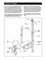
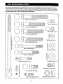
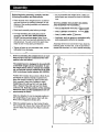
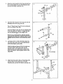
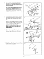
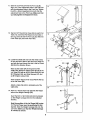
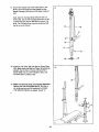
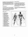
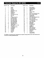
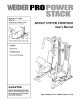
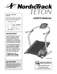
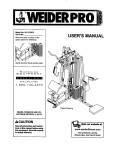
USER'S MANUAL
Model No. 831.150760
Serial No.
Write the serial number in the space
above for future reference.
Serial Number Decal (Under Seat)
EXERCISE
I
H
F'Lp
LI
N
E
I
I
1-800-736-6879
SEARS, ROEBUCK AND CO.,
HOFFMAN ESTATES, IL 60179
www.weiderfitness.co
m
n:ew products,
prizes,
fitness tips, and much more!
WARNING DECAL PLACEMENT
...........................................................
IMPORTANT PRECAUTIONS ..............................................................
BEFORE YOU BEGIN ...................................................................
PART IDENTIFICATION CHART ............................................................
ASSEMBLY
...........................................................................
USING THE WEIGHT BENCH ............................................................
EXERCISE GUIDELINES ................................................................
PART LIST ...........................................................................
EXPLODED DRAWING
.................................................................
ORDERING REPLACEMENT PARTS ................................................
FULL 90 DAY WARRANTY ...................................
The decal shown at the right has
been applied to the weight bench.
If the decal is missing, or if it is
not legible, please call our toll-free
HELPLINE at 1-800-736-6879,
Monday through Saturday, 7 a.m.
until 7 p.m. Central Time (excluding holidays), to order a free
replacement decal. Apply the
replacement decal in the location
shown.
,. ....................
_9
• Misuseofthisproduct
.ma.y
resultin serious
mjun].
• Readuser'smanual
andfollowallwamings
andoperatinginstructionspriortouse.
• Donotallowchildren
onoraroundmachine.
• Replacelabelif
damaged,illegible,
or
removed.
2
2
3
4
5
6
11
13
18
19
Back Cover
Back Cover
,WAR
NING:
To reduce the rlsk of serious injm¥
before using tt e We gh bench,
read th_fbllowing
imp0rlant
Read "311instdJctions
in this manual before
using the weight bench.
2,
It is the responsibility
of the owner
to ensure
that all Useis otthu
wnight
bench are adequately
informed
of all precautions
3
Use
the
th_s
manual
4
weight
Use the weight
Cover the tloor
protection.
bench
onty
as
described
13. Wher_ iJsin
lion. t
it]
ed completetythrough
both dpr_ghts
nnd
that the "sup_rt
rod is turned to ttie tocked
bench onl T on _ level surface•
beneath the weight bench for
position.
_ddii
3
Thank you for selecting the WELDER e PRO900 Weight
Bench. The versatile WELDER • PRO900 Weight
Bench is designed to be used with your own weight
set (not included) to develop every major muscle
group of the body. Whether your goal is a shapely figure, dramatic muscle size and strength, or a healthier
cardiovascular system, the WELDER • PRO900 will
help you to achieve the specific results you want.
HELPLINE at 1-800-736-6879, Monday through
Saturday, 7 a.m. until 7 p.m. Central Time (excluding
holidays). To help us assist you, please note the product model number and serial number before calling.
The model number is 831.150760. The sedal number
can be found on a decal attached to the WELDER •
PRO900 (see the front cover of this manual).
Before reading further, please look at the drawing
below and familiadze yourself with the parts that are
labeled.
For your benefit, read this manual carefully before
using the WELDER e PRO900 Weight Bench. If you
have additional questions, please call our toll-free
Lat Bar
Lat
Tower
Weight Rests
Weight
Tube
Upright
Cud
Pad
Knob
Backrest
Tubes
-Seat
Leg Lever
Weight
Tube --
4
This chart is provided to help you identify the small parts used in assembly. The number in parenthesis below
each part refers to the key number of the part. The second number refers to the quantity needed for assembly.
Important: Some parts may have been pre-assembled for shipping purposes. If you cannot find a part in
the parts bags, check to see if it has been pre-assembled.
_
_\\\\\\\\\\\\\\\\\\\_
MIO x 81mm Bolt (43)--10
_,
r-]
0
_\\\\\\\\\\\\\\\\\\\I
Narrow Spacer (30)-"
MIO x 72mm Bolt (53)--1
_, _\\\\\\\\\\\\\\\\\\\!
Wide Spacer (47)-2
MIO x 67mm Bolt (14)--2
_, _\\\\\\\\\\\\\\\\\\\!
M6 Washer (25)--4
MIO x 65mm Bolt (18)4
£
_\\\\\\\\\\_
. M8 x 70mm Bolt (54)_1
M8 Washer (48)---2
_\\\\\\\\\\_
M8 x 58mm Bolt (49)_1
\\\\\\\_
M10 Washer (24)--12
M6 x 38mm Screw (16)--4
Cq
M8 Nylon Locknut (13)--2
o
©
u)
E
E
MIO x 19mm Bolt (46)---1
x
M6 x 16mm Screw (15)_
5
MIO Nylon Locknut (19)---20
Before beginning assembly, carefully read the
following information and instructions:
• As you assemble the weight bench, make sure
that all parts are oriented as shown in the drawings.
• Place all parts of the weight bench in a cleared
area and remove the packing materials; do not
dispose of the packing materials until assembly
is completed.
THE FOLLOWING TOOLS (NOT INCLUDED)
ARE REQUIRED FOR ASSEMBLY:
• Two (2) adjustable wrenches
• Read each assembly step before you begin.
• One (1) phillips screwdriver
• For help identifying the small parts used in
assembly, use the PART IDENTIFICATION
CHART on the previous page. Note: Some
small parts may have been pre-attached for shipping purposes. If a part is not in the parts bag,
check to see if it has been pre-attached.
• One (t) rubber mallet
• Lubricant, such as grease or petroleum jelly,
and soapy water will also be needed.
Assembly will be more convenient if you have the
following tools: A socket set, a set of open-end or
closed-end wrenches, or a set of ratchet wrenches.
•l]ghten
all parts as you assemble them, unless
instructed to do otherwise.
P
• 1.
Before assembling this weight bench, be sure
that you have read and understand the information in the box above.
The weight bench is designed to be used with
a mid,width weight set (not included). To use
the weight bench with an olympic-size weight
set, an optional olympic expansion kit is available to purchase (model number 831.150780).
Position the Crossbar (3) as shown. (Note: If you
purchased the optional olympic expansion kit,
place the olympic crossbar in place of the standard crossbar.) Attach the Crossbar to each
Upright Base (7) with four M10 x 81mm Bolts
(43), a Support Plate (20) and four M10 Nylon
Locknuts (19). Note the position of the warning
decal and make sure the Upright.Bases are oriented exactly as shown.
Slide the Uprights (1) into the desired position in
the Upright Base (7) and secure them with two
M10 x 67mm Adjustment Knobs (37).
2.
Slide the welded bracket on the Frame (2) onto
the Crossbar (3). Secure the Frame with two M10
x 81mm Bolts (43) and two M10 Nylon Locknuts
(19).
19
3
6
Attach the Front Leg (8) to the Frame (2) with two
M10 x 65mm Bolts (18), two M10 Washers (24),
and two MIO Nylon Locknuts (19).
.
f
1
_----19
<
Tap three 45mm Square Inner Caps (21) into the
indicated ends of the Leg Lever (4).
4.
4
_21
Tap a 1" Round Inner Cap (23) into the indicated
end of the Weight Tube (52).
Insert the Weight Tube (52) into the indicated hole
in the Leg Lever (4). Press a 1" Angle Cap (50)
onto the indicated end of the Weight Tube.
Note: If you purchased the optional olympic
expansion Idt, attach the olympic sleeve to the
Weight Tube as shown in the accessory manual.
Lubricate an MIO x 72ram Bolt (53). Attach the
Leg Lever (4) to the Front Leg (8) with the Bolt
and an M10 Nylon Locknut (19).
5_
19
Attach the Narrow Spacer (30) to the Leg Lever
(4) with the M8 x 58mm Bolt (49), two M8
Washers (48), and an M8 Nylon Locknut (13).
Note: The Spacer will fit tightly inside of the
Leg Lever.
.
Attach the Frame (2) to the Lat Tower Base (35)
with two M10 x 67mm Bolts (14), two MIO
Washers (24), and two M10 Nylon Locknuts (19).
•
19
,:
"" I
>
7
J3_14
24
>
7.
Press four 1" Square Inner Caps (12) into the
indicated ends of the Backrest Tubes (5, 55).
Press two 1" x 2" Inner Caps (45) into the ends of
the adjustment tubes.
7
Wide
End
12
With the wide end of the Backrest (6) positioned
as shown, attach the Backrest Tubes (5, 55) to
the Backrest (6) with four M6 x 38mm Screws
(16) and four M6 Washers (25). The Backrest
Tubes and Backrest must be oriented exactly
as shown.
16
ustment
_"25
16
8.
Lubricate the M10 x 178mm Bolt (17). Attach the
Backrest (6) to the Frame (2) with the Bolt, two
M10 Washers (24), and an M10 Nylon Locknut
(19).
Tubes
• 6
Secure the Backrest (6) to the Frame (2) with the
Adjustment Pin (40) through one of the three sets
Tubes
of holes in the ad_stment tubes. Secure the
Adjustment Pin with the Pin Clip (57).
Make sure the Adjustment Pin (40) is completely inserted through both holes in the
adjustment tubes.
9.
2
With the wide end of the Seat (11) positioned as
shown, attach the Seat to the brackets on the
Frame (2) with four M6 x 16mm Screws (15).
9
11
Wide
15
10. Attach the Curl Pad (28) to the Curl Post (27) with
two M6 x 16mm Screws (15).
10
28
8
%
"--_57
11. Slide the Curl Post (27) into the Front Leg (8).
Align one of the adjustment holes in the Curl Post
with the adjustment hole in the Front Leg. Tighten
the M 10 x 48mm Adjustment Knob (41) into the
adjustment hole in the Front Leg. Make sure that
you fully tighten the Adjustment Knob.
11
12. Tap two 3/4" Round Inner Caps (9) into each Pad
Tube (10). Insert the Pad Tubes into the holes in
the Leg Lever (4) and the Front Leg (8). Slide two
Foam Pads (22) onto each Pad Tube.
12
22
4/
10
13. Locate the Cable (34) and note that it has a loop
on one end and a ball on the other end. Insert the
end with the loop through the slot In the Lat Tower
(26) from the direction shown.
47
13
Next, lay the Cable (34) in the groove of the
Pulley (29). Attach the Pulley inside the slot in the
Lat Tower (26) with an M10 x 65mm Bolt (18), two
M10 Washers (24), two Wide Spacers (47), and
an M10 Nylon Locknut (19).
34
19
Press a 5Omm Square Inner Cap (44) into the top
of the Lat Tower (26).
Attach a Cable Clip (33) to indicated end of the
Cable (34).
14
14. Press a 1" Round Inner Cap (23) into the weight
tube on the Weight Carriage (32).
Bracket
Insert the M10 x 19mm Bolt (46) into the bracket
on the Weight Carriage (32) from the indicated
direction.
23
Note the position of the Lat Tower (26) in step
13. The Lat Tower must be positioned in this
manner. Slide the Weight Carriage (32) onto the
Lat Tower. Make sure that the Weight Carriage
is oriented as shown.
46
9
15. Secure the looped end of the Cable (34) to the
M19 x 19ram Bolt (46) and the bracket on the
Weight Carriage (32) with an M10 Nylon Locknut
(19).
15
Next, slide the Carriage Stop (39) onto the Lat
Tower (26). Secure the Carriage Stop with an M8
x 70mm Bolt (54) and an M8 Nylon Locknut (13).
Note: The Carriage Stop must be positioned with
the lip on top as shown.
16. Insert the Lat Tower (26) into the I_atTower Base
(35). Make sure that the I-at Tower is turned as
shown. Secure the Lat Tower with two M10 x
16
65mm Bolts (18), four M10 Washers (24), and
two M10 Nylon Locknuts (19).
26
17. Make sure that all parts are properly tightened
before you use the weight bench. The use of
all remaining parts will be explained in USING
THE WEIGHT BENCH on pages l__and 12.
..... 24
10
The weight bench is designed to be used with your own weighl set (not included). The steps below explain how
the weight bench can be adjusted. See EXERCISE GUIDELINES on page 13 for important exercise information
and refer to the accompanying exercise poster to see the correct form for several exercises. Refer also to the
exercise information accompanying your weight set (not included) for additional exercises.
Inspect and tighten aH parts each time you use the weight bench. Replace any worn parts immediately. The
weight bench can be cleaned with a damp cloth and a mild, non-abrasive detergent. Do not use solvents•
ADJUSTING
THE BACKREST
40
The Backrest (6) can be used in either a decline position, a level position or two incline positions• To adjust
the Backrest to the decline position, remove the
Adjustment Pin (40) and lower the Backrest until it
rests directly on the Crossbar (3). Re-insert the
Adjustment Pin.
To adjust the Backrest (6) to the level position, insert
the Adjustment Pin (40) through the top set of holes.
$,,
To adjust the Backrest (6) to an incline position, insert
the Adjustment Pin (40) as shown through one of the
three sets of holes in the backrest adjustment tubes.
Slide the Adjustment Pin completely through both
holes in the adjustment tubes. Secure the Adjustment
Pin with the Pin Clip (57).
ATTACHING
57
3
Adjustment Tubes
WEIGHTS TO THE LEG LEVER
To use the Leg Lever (4), slide the desired weights
(not included) onto the Weight Tube (52).
Weight
Note: If you purchased the optional olympic expansion kit, attach the olympic sleeve to the weight
tube as shown in the accessory manual.
ATTACHING
THE LAT BAR
33---_i'-..
TO THE LAT TOWER
26 ....
4".
"_
To use the Lat Tower (26), atlach the Lat Bar (36) to
the Cable (34) with a Cable Clip (33)•
36
11
ATTACHING WEIGHTS
TO THE LAT TOWER
To use the Lot Tower (26), slide the desired amount of
weighl (not included) onto the weight tube on the
Weight Carriage (32).
V
26J
i
32
::.i_tt'>"_
:};
ADJUSTING
THE UPRIGHTS
The Uprights (1) can be adjusted to five heights to
accommodate different exercises. To adjust the
height, remove the M10 x 67ram Adjustment Knobs
(37) from both Uprights and Upright Bases (7). Slide
the Updghts to the desired position and re-insert the
Adjustment Knobs..
l_
I-i_jcll_
ATTACHING
THE CURL POST
Note: When the Curl Post (27) is not iQ4Jse, the
-.45mm Square Inner Cap (21) should be inserted into
the Front Leg (8).
21
For some exercises, the Curl Post (27) must be
attached to the weight bench.
Slide the Curl Post (27) into the Front Leg (8). Align
one of the adjustment holes in the Curl Post with the
adjustment hole in the Front Leg. Tighten the MIO x
48ram Adjustment Knob (41) into the adjustment hole
in the Front Leg. Make sure that you fully tighten
the Adjustment
Knob.
12
Weight
THE FOUR BASIC TYPES OF WORKOUTS
PERSONALIZING YOUR EXERCISE PROGRAM
• Muscle Building
We have not specified an exact length of time for
each workout, or a specific number of repetitions or
sets for each exercise. It is very important to avoid
overdoing it during the first few months of your exercise program, and to progress at your own pace. If
you experience pain or dizziness at any time while
exercising, stop immediately and begin to cool down.
Find out what is wrong before continuing. Remember
that adequate rest and a proper diet are also important.
In order to increase the size and strength of your
muscles, you must push your muscles to a high percentage of their capacity. You must also progressively
increase the intensity of your exercise so that your
muscles will continually adapt and grow. Each individual exercise can be tailored to the proper intensity
level by changing the amount of weight used, or the
number o! repetitions or sets performed. (A "repetition" is one complete cycle of an exemise, such as
one sit-up. A "set" is a series of repetitions performed
consecutively.)
The proper amount of weight for each exercise
depends upon the individual user. It is up to you to
gauge your limits. Select the amount of weight that
you think is right for yo_. Begin with 3 sets of 8 repetitions for each exercise that you perform. Rest for 3
minutes after each set. When you can complete 3
sets of 12 repetitions without difficulty, increase the
amount of weight.
• Toning
To tone your muscles, you must push your muscles to
a moderate percentage of their capacity. Select a
moderate amount of weight and increase the number
of repetitions in each set. Complete as many sets of
15 to 20 repetitions as possible without discomfort.
Rest for t minute after each set. Work your muscles
by completing more sets rather than by using high
amounts of weight.
WARMING UP
Begin each workout with 5 to 10 minutes of light
stretching and exercise to warm up. Warming up prepares your body t_ exercise by increasing circulation,
raising your bodytemperature and delivering more
oxygen to your muscles.
WORKING OUT
Each workout shouldinclude 6 to 10 different exercises. Select exercises for every major muscle group,
with emphasis on the areas that you want to develop
the most. To give balance and variety to your workouts, vary the exercises from workout to workout.
Schedule your wod(outs for the time of day when your
energy level is the highest. Each workout should be
followed by at least one day of rest. Once you find the
schedule that is dgt=tfor you, stick with it,
EXERCISE FORM
In order to obtainthe greatest benefits from exercising, it is essentialto maintain proper form.
• Weight Loss
To lose weight, use a low amount of weight and
increase the number of repetitions in each set.
Exercise for 20 to 30 minutes, resting for a maximum
of 30 seconds between sets.
Maintaining proper form means moving through the
full range of motion for each exercise, and moving
only the appropriate parts of the body. Exercising in
an uncontrolled manner will leave you feeling
exhausted. On the exercise poster accompanying this
manual, you will find photographs showing the correct
form for several exercises. A description of each exercise is also provided, along with a list of the muscles
affected. Refer tol_e muscle chart on page 14 to find
the locations of the muscles.
• Cross Training
In the pursuit of a complete and well-balanced fitness
program, many have found that cross training is the
answer. We recommend that on Monday, Wednesday
and Friday, you plan weight training workouts. On
Tuesday and Thursday, plan 20 to 30 minutes of aerobic exercise, such as cycling, running or swimming.
Rest from both weight training and aerobic exercise
for at least one full day each week to give your body
time to regenerate. By combining weight training with
aerobic exercise, you can reshape and strengthen
your body, plus develop a stronger heart and lungs.
The repetitions in each set should be performed
smoothly and withoutpausing. The exertion stage of
each repetition should last about half as long as the
return stage. Proper br6athing is important. Exhale
during the exertion stage of each repetition and inhale
dudng the return stroke; never hold your breath. Rest
13
for 3 minutes after each set if you are doing a muscle
building workout, 1 minute after each set if you are
doing a toning workout, and 30 seconds after each set
if you are doing a weight loss workout. Plan to spend
the first couple of weeks familiarizing yourself w_ththe
equipment and learning the proper form for each exercise.
COOLING DOWN
End each workout with 5 to t 0 minutes of stretching.
(nclude stretches for both your arms and legs. Move
slowly as you stretch--do not bounce. Ease into each
stretch gradually and go only as far as you can without
strain. Stretching at the end of each workout is very
effective for increasing flexibility.
STAYING MOTIVATED
For motivation, keep a record of each workout. The
charts on pages 15 and 16 of this manual can be
photocopied and used to schedule end record your
workouts. List the date, exercises performed, weight,
and numbers of sets and repetitions completed.
Record your weight and key body measurements at
the end of every month.
Remember, the key to achieving the greatest results is
to make exercise a regular and enjoyable part of your
everyday life.
MUSCLE CHART
A.
B.
C.
D.
E.
F.
G.
H.
I.
J.
K.
L.
M.
N.
O.
P.
Q.
R.
Stemorcastoid (neck)
Pectoralis Major (chest)
Biceps (front of arm)
Obliques (waist)
_.
Brachioradials (forearm)
Hip Rexors (upper thigh)
Abductor (outer thigh)
Quadriceps (front of thigh)
Sartodus (front of thigh)
Tibialis Anterior (front of calf).
Soleus (front of calf)
Rectus Abdominus (stomach)
Adductor (inner thigh)
Trapezius (upper back)
Rhomboldeus (upper back)
Deltoid (shoulder)
Triceps (back of arm)
Latissimus Dorsi (mid back)
H
S. Spinae Erectors (lower back)
T. Gluteus Medius (hip)
U. Gluteus Maximus (buttocks)
-,V. Hamstring (back of leg)
W. Gastrocnemius (back of calf)
14
17
Key No.
Qty.
1
2
3
4
5
6
7
8
9
10
11
12
13
14
15
16
17
18
19
20
21
22
23
24
25
26
27
28
29
2
1
1
1
1
1
2
1
6
3
1
4
2
2
6
4
1
5
20
4
4
6
2
12
4
1
1
1
1
Description
Key No.
Qty.
30
31
32
33
34
35
36
37
38
39
40
41
42
43
44
45
46
47
48
49
50
51
52
53
54
55
56
57
#
#
1
5
1
1
1
1
1
2
2
1
1
1
4
10
1
2
1
2
2
1
1
2
1
1
1
1
1
1
1
1
Upright
Frame
Crossbar
Leg Lever
Left Backrest Tube
Backrest
Upright Base
Front Leg
3/4" Round Inner Cap
Pad Tube
Seat
1" Square Inner Cap
M8 Nylon Locknut
M 10 x 67ram Bolt
M6 x 16ram Screw
M6 x 38mm Screw
M10 x 178mm Bolt
M10 x 65mm Bolt
M_0 Nylon Locknut
Support Plate
45mm Square Inner Cap
Foam Pad
1" Round Inner Cap
Mr0 Washer
M6 Washer
Lat Tower
Curl Post
Curl Pad
Pulley
"#" Indicates a non-illustrated part. Specifications
information on ordering replacement parts.
Description
Narrow Spacer
Cardage Bushing
Weight Cardage
Cable Clip
Cable
Lat Tower Base
Lat Bar
Mt 0 x 67ram Adjustment Knob
60mm x 50mm Bushing
Carriage Stop
Adjustment Pin
M10 x 48ram Adjustment Knob
M4 x 16mm Screw
M 10 x 81 mm Bolt
50mm Square Inner Cap
1" x 2" Inner Cap
MI0 x 19ram Bolt
Wide Spacer
M8 Washer
M8 x 58mm Bolt
1" Angle Cap
Handgrip
Weight Tube
MI0 x 72ram Bolt
M8 x 70mm Bolt
Right Backrest Tube
Stop Screw
Pin Clip
User's Manual
Exercise Poster
are subject to change without notice. See the back cover for
1B
1
23
28
55
18
42
18
19
45
14
2O
21
19
41
17
19
2
19
19
57
Model No. 831.150760
QUESTIONS?
The model number and serial number of your WELDER"
PRO900 ere listed on a decal attached to the frame. See the
front cover of this manual to find the location Of the decal.
If you find that:
* you need help assembling or
operating the WELDER + PRO900
• a part is missing
• or you need to schedule repair
service
All replacement parts are available for immediate purchase or
special order when you visit your nearest SEARS Service
Center. To request service or to order parts by telephone, call
the toll-free numbers listed at the left.
When requesting help or service, or ordering parts, please be
prepared to provide the following information:
call our toll-free HELPLINE
• The MODEL NUMBER of the product (831.150760)
1-800-736-6879
Monday-Saturday,
7 am-7 pm
Central Time (excluding holidays)
• The NAME of the product (WELDER e PRO900 Weight Bench)
- The PART NUMBER of the PART (see the PART LIST and the
EXPLODED DRAWING on pages 18 and 19 of this manual)
REPLACEM*ENT
PARTS
• The DESCRIPTION of the PART (see the PART LIST and the
EXPLODED DRAWING on pages 18 and 19 of this manual).
If parts become worn and need to
be replaced, call the following
free number
toll-
1-800-FON-PART
(1-800-366-7278)
SEARS, ROEBUCK AND CO., HOFFMAN
ESTATES, IL 60179
For 90 days from the date of purchase, if failure occurs due to defect in matedal or workmanship in this
SEARS WEIGHT BENCH EXERCISER, contact the nearest SEARS Service Center throughout the United
States and SEARS will repair or replace the WEIGHT BENCH EXERCISER, free of charge.
This warranty does not apply when the WEIGHT BENCH EXERCISER is used commercially
purposes.
or for rental
This warranty gives you specific legal rights, and you may also have other rights which vary from state to
state•
SEARS, ROEBUCK AND CO., DEPT. 817WA, HOFFMAN
Part No. 162930 R0400A
ESTATES, IL 60179
Printed in China © 2000 Sears, Roebuck and Co.