1
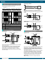
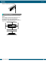
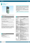
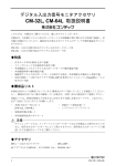
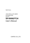
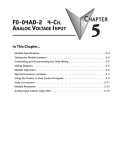
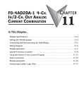
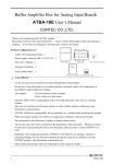
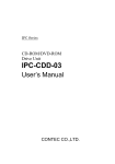
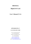
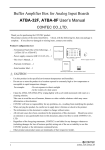
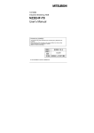
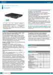
Ver.1.01
Ethernet Remote I/O F&eIT N Series
Isolated Digital Input/Output Unit
DIO-1616LN-FIT
* Specifications, color and design of the products are subject to
change without notice.
This product is an isolated digital input and output unit of F&eIT
remote I/O system that realizes monitoring and control of
devices scattered remotely, through PCs connected to Ethernet.
Since existing network infrastructure can be used, the system
can be built easily by just connecting with LAN cables.
It is possible to connect external devices, such as adjacent
switches, lamps and LEDs, to perform input/output of digital
signals.
Compact design not restricting installation location (188.0(W) x
78.0(D) × 30.5(H)) makes it easy to install the product within
the panel or device using DIN rail mounting jigs, or on the floor
or wall.
Windows driver library is supplied. It is possible to confirm the
operations through the diagnosis monitor without any
programming.
This product has the 16ch of Optocoupler isolated inputs and
16ch of Optocoupler isolated open-collector outputs (input : 12
- 24VDC specification, output : 12 - 48VDC specification).
Input section corresponds to both of current sink and current
source outputs. The output rating is max. 24VDC, 150mA or
48VDC, 50mA per ch.
Features
Optocoupler isolated inputs (for use with current sink
output / current source output), Optocoupler isolated
open-collector outputs (current sink type)
This product has the 16ch of Optocoupler isolated inputs (for
use with current sink output / current source output) and 16ch
of Optocoupler isolated open-collector outputs (current sink
type).
The output rating is max. 24VDC, 150mA or 48VDC, 50mA per
ch. Common terminal provided per 8ch, capable of
supporting a different external power supply. You can check
the digital input or output by using the LED indicator.
Optocoupler bus isolation
As the Ethernet controller (PC) side is isolated from the input
and output interfaces by Optocouplers, this product has
excellent noise performance.
This product has a digital filter to prevent wrong
recognition of input signals from carrying noise or a
chattering.
This product has a digital filter to prevent wrong recognition of
input signals from carrying noise or a chattering. All input
terminals can be added a digital filter, and the setting can be
performed by software.
Fail safe function
When communication failure occurs, such as LAN cable
disconnection, it is possible to notify the external devices by
outputting a specific user-defined signal pattern.
Compact design not restricting installation location
(188.0(W) x 78.0(D) x 30.5(H))
Compact design of 188.0(W) × 78.0(D) × 30.5(H) does not
require special installation location.
Compatible with a wide range of power supplies : 5 to
24VDC
Compatible with a wide range of power supplies : 5 to 24VDC,
and can be used in various environments.
An FG terminal is also provided in the power connector.
Furthermore, it is possible to screw fit the power connector on
to the body to prevent detachment.
Can be used as digital input/output of Ethernet base
remote I/O
As the control (monitoring and control) of digital input/output is
performed via Ethernet, remote control can be easily
performed.
DIO-1616LN-FIT
Diverse installations such as screw fastening, magnet, DIN
rail are possible
Installation on the floor / wall /ceiling is possible by screw
fastening, magnet, rubber feet, etc.
In addition, DIN rail mounting mechanism is equipped as
standard with the product, making it easy to install the product
within the panel or the device.
Windows compatible driver libraries are attached.
Using the attached driver library makes it possible to create
applications of Window. As the driver library was designed
taking into consideration compatibility with the API functions
[API-PAC(W32)] of the measurement control and
communication interface board, if you have experience in these
applications, smooth programming is possible.
In addition, a diagnostic program by which the operations of
hardware can be checked is provided.
In addition, using generic socket functions makes it possible to
implement control under OS other than Windows, such as
UNIX machine.
Specification
Specifications < 1 / 2>
Item
Input section
Input format
Input resistance
Input ON current
Input OFF current
Number of input signal
channels
Response time
External circuit power
supply
Output section
Output format
Ratings
Output
voltage
Output
current
Number of output signal
channels
Response time
External circuit power
supply
Common section
Allowable distance of
signal extension
Applicable wire
Applicable plug
Specifications
Optocoupler isolated input
(compatible with current sink output and current source output)
4.7kΩ
2.0mA or more
0.16mA or less
16 channels (8 channels / common)
Within 1msec
12 - 24 VDC (±15%)
(2.5 mA / 12V, 5 mA / 24V per channel)
Optocoupler isolated open collector output (current sink type)
12 - 48VDC (±15%)
150 mA (12 - 24V) (per channel) (Max.)
50 mA (36 - 48V) (per channel) (Max.)
16 channels (8 channels / common)
Within 1msec
12 - 48VDC (±15%)
Approx. 50m (depending on wiring environment)
AWG28 - 16
AK1550 / 10-3.5-GREEN (mfd. by PTR)
1
Ver.1.01
Specifications < 2 / 2>
Current consumption
(Max.)
FG pin
Power input connector
Specifications
10/100BASE-TX(IEEE802.3u)
5 - 24VDC±10% supply from 2-piece power input detachable
type connector
It is recommended that you use F&eIT series power unit or
stabilized power product on the market.
Maximum extension between power device and the product :
1.5m
5VDC 0.60A, 12VDC 0.26A, 24VDC 0.14AA
Power supply connector equipped with a FG pin.
2-piece power input detachable type connector with an FG
terminal supplied
Uses connector : MC1,5/3-GF-3,5 (mfd by Phoenix Contact)
The dedicated plug, with screw fastening that can be operated
from the side, is supplied as standard
Compatible connector : MC1,5/3-STF-3,5 (mfd by Phoenix
Contact)
Compatible cable : AWG28-16
Physical dimensions (mm) 188.0(W) x 78.0(D) x 30.5(H) (No protrusions)
Weight
220g (Only the unit)
Installation method
One-touch connection to 35mm DIN rails
DIN rail mounting mechanism as a standard feature.
Mounting to the wall using the screws
Mounting to a metal surface using the magnets
Mounting to the floor using the rubber feet
Packing List
Unit [DIO-1616LN-FIT] …1
First step guide … 1
Power connector …1
I/O connector …4
Rubber feet …4
Magnet …2
CD-ROM [F&eIT Series Setup Disk] *1 …1
*1
The CD-ROM contains various software and User’s Manual.
Physical Dimensions
(55)
66
78
Item
LAN
Power voltage
Installation Environment Requirements
(4)
(154)
170
188
f3.5
20
30.5
Requirement description
0 - 50°C *1
10 - 90%RH (No condensation)
Not to be excessive
None
AC line / 2kV, Signal line / 1kV
(IEC1000-4-4Level 3, EN61000-4-4Level 3)
Contact discharge / 4kV (IEC1000-4-2Level 2, EN61000-4-2Level 2)
Atmospheric discharge / 8kV
(IEC1000-4-2Level 3, EN61000-4-2Level 3)
10 - 57Hz / semi-amplitude 0.15mm, 57 - 150Hz / 2.0G
40minutes each in X, Y, and Z directions
(JIS C60068-2-6-compliant, IEC60068-2-6-compliant)
Impact resistance
15G half-sine shock for 11ms in X, Y, and Z directions
(JIS C60068-2-27-compliant, IEC60068-2-27-compliant)
Grounding
Class D grounding (previous class 3 grounding)
*1 When using the attached AC adaptor POA201-10-2, it is 0 - 40°C
*2 When using a POA201-10-2
(mm)
4
Item
Operating temperature
Operating humidity
Floating dust particles
Corrosive gases
Noise
Line-noise
immunity *2
Static
electricity
resistance
Vibration Sweep
resistance resistance
Physical Dimensions<AC Adapter POA201-10-2(Option)>
Model with 2P Inlet, no polarity
UL,VDE standard product
Support Software
API-CAP(W32)
[Stored on the bundled CD-ROM F&eIT Series Setup Disk]
The API-CAP(W32) is the Windows version driver library
software that provides products in the form of Win32 API
functions (DLL). Various programming languages such as
Visual Basic and Visual C++ can be used to create high-speed
application software which maximizes the features of the F&eIT
module. In addition, a diagnostic program, which is useful for
operation verification, is also provided.
[mm]
Connecting an Interface Connector
When connecting the unit to an external device, you can use
the supplied connector plug. When wiring the unit, strip off
approximately 7 mm of the covering for the cable, and insert
the bare wire by pressing the orange button on the connector
plug. Releasing the orange button after the wire is inserted
fixes the cable. Compatible wires are AWG 28 - 16.
< Operating environment >
OS
Windows 7, Server 2008, Vista, XP,
2000., etc
Adaptation language Visual C++, Visual Basic., etc
For more details on the supported OS, applicable language
and how to download the updated version, please visit the
CONTEC’s Web site (http://www.contec.com/).
7mm
Option list
POA201-10-2 : AC adapter
(input : 90 - 264VAC, output : 12VDC 1.0A)
POA200-20-2 : AC adapter
(input : 90 - 264VAC, output : 5VDC 2.0A)
POW-AD13GY : AC-DC power unit
(input : 85 - 132VAC, output : 5VDC 3.0A)
POW-AD22GY : AC-DC power unit
(input : 85 - 264VAC, output : 5VDC 2.0A)
POW-DD10GY : DC-DC power unit
(input : 10 - 30VAC, output : 5VDC 3.0A)
POW-DD43GY : DC-DC power unit
(input : 30 - 50VAC, output : 5VDC 3.0A)
*
- Connector used :
3.5mm pitch, 10 pin type of rated current 9.0A
STL1550/10G-3.5-H-GREEN [mfd. by PTR]
- Compatible plug (supplied) :
AK1550/10-3.5-GREEN [mfd. by PTR]
Compatible wires : AWG28-16
CAUTION
Removing the connector plug by grasping the cable can
break the wire.
Check the CONTEC’s Web site for more information on these options.
DIO-1616LN-FIT
2
Ver.1.01
Connecting a Switch
The unit can be connected to an external device using 10-pin
connectors that is provided on the unit face.
Connector : 4
INPUT 1
COM N.C. 7 6 5 4 3
INPUT1
0 COM N.C. 7 6 5 4 3
2 1
Signal
name
Logical
bit
0
1
2
3
4
5
6
7
IN00
IN01
IN02
IN03
IN04
IN05
IN06
IN07
0
1
2
3
4
5
6
7
0
N.C.
N.C.
-
-
-
Pin No.
INPUT0
INPUT 0
COM
COM
-
0
1
2
3
4
5
6
7
IN10
IN11
IN12
IN13
IN14
IN15
IN16
IN17
8
9
10
11
12
13
14
15
N.C.
COM
N.C.
Logical
port
-
COM
-
OUTPUT 1
2 1
0COMCOM7 6 5 4 3
1
2
2 1
0 COMCOM7 6 5 4 3
1
2
2 1
0
Logical
bit
Logical
port
Contents
0
1
2
3
4
5
6
7
OUT00
OUT01
OUT02
OUT03
OUT04
OUT05
OUT06
OUT07
0
1
2
3
4
5
6
7
0
Output
Not
connected
COM0
COM(-)
-
-
Plus / minus
common for
INPUT0
COM1
COM(+)
-
-
1
Input
0
1
2
3
4
5
6
7
OUT10
OUT11
OUT12
OUT13
OUT14
OUT15
OUT16
OUT17
8
9
10
11
12
13
14
15
1
-
Not
connected
COM0
COM(-)
-
-
-
Plus / minus
common for
INPUT1
COM1
COM(+)
-
-
Pin No.
Input
OUTPUT0
OUTPUT1
+ External
power
supply
12 - 24VDC
-
Input pin
(Ex : Bit 0 of connector INPUT 0)
OUTPUT 0
Signal
name
Contents
Input plus common
(Ex : COM of connector INPUT 0)
Unit side
Signal Layout on the Interface Connector
Examples of Connection to an External Device
Example of a Connection between Input and Current Sink
Output
Unit
External circuit
Vcc
4.7kΩ
Minus
common for
OUTPUT0
Plus
common for
OUTPUT0
Plus
common
External power
supply
12 - 24VDC
Input
pin
Optocoupler
Current
sink
output
Output
Minus
common for
OUTPUT1
Plus
common for
OUTPUT1
Example of a Connection between Input and Current
Source Output
External circuit
Unit
Vcc
IN00 - 17
OUT00 - 17
N.C.
COM
COM0
COM1
16 input signal pins. Connect output signals from the external device to these
pins.
16 output signal pins. Connect these pins to the input signal pins of the
external device.
This pin is left unconnected.
Connect the positive or negative side of the external signal. These pins are
common to 8 input signal pins.
Connect the negative side of the external signal. These pins are common to 8
output signal pins.
Connect the positive side of the external signal. These pins are common to 8
output signal pins.
4.7kΩ
Minus
common
Optocoupler
External power
supply
12 - 24VDC
Input
pin
Current source
output
Connecting Input Signals
Connecting Output Signals
Input Circuit
Unit
Output Circuit
External circuit
Vcc
Unit
4.7kΩ
Plus/
Minus
common
Input
pin
Optocoupler
Input
contact
point
External power
supply
12 - 24VDC
External circuit
Plus
common
Vcc
Output
pin
Load
External power
supply
12 - 48VDC
Optocoupler
4.7kΩ
Vcc
Optocoupler
Input
pin
Input
contact
point
Output
pin
Load
Optocoupler
Figure above shows the input equivalent circuit for the interface
section of this product.
The signal input section consists of an Optocoupler isolated
input (compatible with both current sink output and current
source output). An external power supply is therefore
required to drive the input section of this unit. The power
requirement is about 5 mA per input channel at 24 VDC (about
2.5 mA at 12 VDC).
Minus
common
Figure above shows the output circuit for the interface section
of this product. The signal output section consists of an
Optocoupler isolated open collector output (current sink type).
An external power supply is therefore required to drive the
output section of this unit.
The maximum output current rating per channel is 150 mA (at
12 - 24 VDC) or 50 mA (at 36 - 48 VDC). A surge voltage
protection circuit (zener diode) is provided for the output
transistors of this unit. When the unit drives relays, lamps,
and other induction loads, however, another surge voltage
countermeasure should be provided on the load side.
CAUTION
When the power is turned on, all output will be OFF.
DIO-1616LN-FIT
3
Ver.1.01
Connection to the LED
Unit side
Output plus common
(Ex : COM1 of connector OUTPUT 0)
Installation Method
Load
+
External
power supply
12 - 48VDC
-
Mounting on a DIN Rail
Output pin
(Ex : BIT 0 of connector OUTPUT 0)
Output minus common
(Ex : COM0 of connector OUTPUT 0)
Examples of Connection to an External Device
Example of a Connection between Output and Current
Sink Input
Sink
output-compliant input
External power
supply
Unit
Desktop Installation
When required to mount the product on the desktop, mount it
on a horizontal platform.
The rubber feet can be mounted in their mounting holes as
shown in the following figure.
Output
Output common
Connection Method between Output and Source
Output-Compliant Input
Wall Installation
Unit
To mount the product on the wall, purchase the commercially
available screw (fitting for φ3.5) separately.
Output common
External power
supply
Output
Source
output-compliant
input
Screws
Example of a Connection between Input and Output
Unit
Figure below shows the example of a connection between
input pin of input unit and output pin of output unit.
Installation Using the Magnet
External
power supply
12 - 24VDC
-
+
Attaching the magnet supplied with the product makes it easy
to mount or remove the product on or from a metal surface
such as steel desk or partition.
2
Output unit
Output plus common
1
Input unit
Input plus common
Output pin
Input pin
Output minus common
DIO-1616LN-FIT
4
Ver.1.01
Example of a Mounting on the partition
Installation Condition
50mm
or more
Spacing between the system unit and any surrounding
objects
Secure a distance of at least 50mm between the top of the
main unit (single use) and any surrounding objects.
Do not locate the unit in a fully enclosed housing.
It is possible to mount it in the orientations shown in the
following figure. Other orientations would cause problems in
usage, such as inadequate heat dissipation.
50mm
or more
5
234 6
78 9
D
ABC E
50mm
or more
F0 1
5
2 34 6
D
ABC E
78 9
50mm
or more
50mm
or more
F0 1
DIO-1616LN-FIT
5