1
GLOFA
G3F-PIDB
G4F-PIDB
LS Programmable Logic Controller
y Read this manual carefully before installing, wiring, operating, servicing or inspecting this equipment.
y Keep this manual within easy reach for quick reference.
SAFETY PRECAUTIONS
Be sure to read carefully the safety precautions given in data sheet and user’s manual before operating the module
and follow them.
The precautions explained here only apply to the G3F-PIDB and G4F-PIDB.
For safety precautions on the PLC system, see the GLOFA GM3/4 User’s Manuals.
A precaution is given with a hazard alert triangular symbol to call your attention, and precautions are represented as
follows according to the degree of hazard.
!
WARNING
If not provided with proper prevention, it can cause death or fatal
injury or considerable loss of property.
!
CAUTION
If not properly observed, it can cause a hazard situation to result
in severe or slight injury or a loss of property.
However, a precaution followed with
!
CAUTION can also result in serious conditions.
Both of two symbols indicate that an important content is mentioned, therefore, be sure to observe it.
Keep this manual handy for your quick reference in necessary.
Installation Precautions
!
CAUTION
▶ Operate the PLC in the environment conditions given in the general specifications.
▶ If operated in other environment not specified in the general specifications, it can cause
an electric shock, a fire, malfunction or damage or degradation of the module
▶ Make sure the module fixing projections is inserted into the module fixing hole and fixed.
▶ Improper installation of the module can cause malfunction, disorder or falling.
Test Run and Maintenance
Precautions
!
CAUTION
▶ Do not separate the module from the printed circuit board(PCB), or do not remodel the module.
They can cause disorder, malfunction, damage of the module or a fire.
When mounting or dismounting the module, perform them after the power has been turned
off.
▶ Do not perform works while the power is applied, which can cause disorder or malfunction.
Waste Disposal Precautions
!
CAUTION
▶ When disposing the module, do it as an industrial waste.
◎
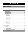
Chapter 1.
1.1
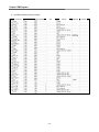
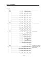
CONTENTS
◎
INTRODUCTION
Features ············································································································· 1-1
Chapter 2.
SPECIFICATIONS
2.1
General specifications ························································································ 2-1
2.2
Performance specifications ················································································· 2-2
2.3
Names of parts and functions ·············································································· 2-3
2.4
PID control action ······························································································ 2-5
2.4.1 Processing type ·····················································································································2-5
1) Velocity type processing ·········································································································· 2-5
2) Measured value derivative type (Pre-derivative type) ······································································2-5
2.4.2 Control actions ························································································································2-6
1) Proportional action (P action) ···································································································· 2-6
2) Integral action (I action) ···········································································································2-8
3) Derivative action (D action) ····································································································· 2-10
4) PID action ··························································································································· 2-11
5) PID processing expression ····································································································· 2-11
6) Forward/Reverse actions ······································································································· 2-12
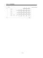
2.5 Auto-tuning ····························································································································· 2-13
1) Auto-tuning block diagram······································································································ 2-13
2) Sequence of auto-tuning ······································································································ 2-13
2.6 Set value (SV) –ramp function ··································································································· 2-15
2.7 PWM control output ················································································································· 2-16
2.8 ON/OFF control ······················································································································ 2-17
2.9 Manipulated value upper/lower limit function ················································································· 2-17
2.10 MV value output limit function ·································································································· 2-18
2.11 Output upper/lower limit function ······························································································· 2-18
2.12 Change from manual control mode to PID control mode ································································ 2-18
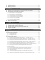
Chapter 3.
INSTALLATION
3.1
Installation ambience ························································································· 3-1
3.2
Handling precautions ························································································· 3-1
Chapter 4.
4.1
FUNCTION BLOCKS
Insertion of the function blocks for PID control module on the GMWIN ····················· 4-1
4.2 Function Blocks used in PID control module ························································· 4-2
4.2.1 Module Initialization for array type(PIDBAINI) ···············································································4-2
4.2.2 Module Initialization for single type(PIDBINI) ················································································4-3
4.2.3 Controlling calculation for array type( PIDBACAL) ·········································································4-4
4.3.4 Controlling calculation for single type( PIDBCAL) ············································································4-5
4.3.5 Auto tuning for array type( PIDBAAT) ·························································································4-6
4.3.6 Auto tuning for single type( PIDBAT) ····························································································4-7
4.3
Errors on function block······················································································· 4-8
Chapter 5.
GM PROGRAMMING
5.1
Program example using G3F-AD4B module ··························································· 5-1
5.2
Program using the auto tuning function(TC module used) ······································ 5-6
5.3
Program using PWM ···························································································5-10
Chapter 6.
BUFFER MEMORY CONFIGURATION AND FUNCTIONS
6.1 Buffer memory configuration ················································································· 6-1
6.1.1 G3F-PIDB buffer memory···········································································································6-1
6.1.2 G4F-PIDB buffer memory···········································································································6-3
6.2 Fuctions of buffer memory ····················································································· 6-5
6.2.1 Specifying loop enable/disable(G3F-PIDB : Addresses 0, 1 G4F-PIDB : Address 0) ·····························6-5
6.2.2 Specifying Forward/Reverse Action (G3F-PIDB : Addresses 34,35 G4F-PIDB : Address 17) ··················6-5
6.2.3 Specifying output enable/disable(G3F-PIDB : Addresses 292,293 G4F-PIDB : Address 146)) ················6-6
6.2.4 Specifying set data enable/disable (G3F-PIDB : Addresses 422,423 G4F-PIDB : Address 211) ··············6-6
6.2.5 Specifying ON/OFF action (G3F-PIDB : Addresses 424,425 G4F-PIDB : Address 212)·························6-7
6.2.6 Auto tuning operation enable/disable (G3F-PIDB : Addresses 426,427 G4F-PIDB : Address 213) ···········6-7
6.2.7 Specifying auto/manual operation enable/disable(G3F-PIDB : Addresses 460,461 ,
G4F-PIDB : Address 230) ····················································································································6-8
6.2.8 Auto tuning complete (G3F-PIDB : Addresses 622,623, G4F-PIDB : Address 311)··································6-8
6.2.9 Status Information(G3F-PIDB : Addresses 720,721, G4F-PIDB : Address 360) ······································6-9
6.2.10 Setting PID control data ···········································································································6-9
6.2.11 Alarm Information(G3F-PIDB : Addresses 722~753, G4F-PIDB : Address 361~376)···························· 6-10
6.2.12 Setting error Information(G3F-PIDB : Addresses 754~785, G4F-PIDB : Address 377~392)··················· 6-10
Chapter 7.
DEDICATED INSTRUCTIONS FOR SPECIAL MODULES
Read from buffer memory ⋅ ⋅ ⋅ GET, GETP ······························································· 7-1
7.1
7.2 Write to buffer memory ⋅ ⋅ ⋅ PUT, PUTP ··································································· 7-2
Chapter 8.
8.1
PROGRAMMING
Basic programming ····························································································· 8-1
8.1.1 G3F-PIDB ····························································································································8-1
8.1.2 G4F-PIDB ····························································································································8-2
8.2
Application programming ····················································································· 8-3
8.2.1 Program example using G3F-AD4B module ·················································································8-3
8.2.2 Program using the auto tuning function (TC module used) ······························································8-7
8.2.3 Program using PWM·················································································································8-9
Chapter 9.
TROUBLESHOOTING
9.1
Errors indicated by RUN LED flickering ·································································· 9-1
9.2
Troubleshooting
procedure················································································ 9-1
9.2.1 RUN LED flickering ··················································································································9-1
9.2.2 RUN LED off···························································································································9-1
9.2.3 Unreadable processing result of PID control module ········································································9-2
9.2.4 Run LED of enabled loops off ·····································································································9-2
9.2.5 PID control module hardware defect·····························································································9-2
Chapter 10.
DIMENSIONS
10.1
G3F-PIDB dimensions····················································································10-1
10.2
G4F-PIDB dimensions····················································································10-2
Chapter 1. INTRODUCTION
Chapter 1.
INTRODUCTION
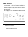
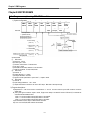
These two modules are called G3F-PIDB and G4F-PIDB. The G3F-PIDB is used with the CPU of GLOFA PLC GM1.2.3
series and MASTER-K 1000S series , The G4F-PIDB is used with the CPU of GM4 series and MASTER-K 300S series.
Hereafter, the two modules will be commonly called the PID control module.
PID control means a control action that in order to keep the object at a value set beforehand (SV), it compares the SV
with a sensor-measured value (PV) and when a difference between them is detected the controller makes PV come to
be SV by adjusting output to eliminate the difference. The PID control is composed of combinations of Proportional (P),
Integral (I) and Derivative (D) actions.
When a difference between SV and PV occurs, proportional, integral, differential quantities are calculated upon that
difference and a MV(Manipulated Value) is output.
1.1 Features
The features of the PID control module are as follows.
1) One module can control various processes separately and at the same time.
2) Forward/reverse action selection is available.
3) Manually manipulated out (forced to be output by the user), not operation processing output, is available.
4) The number of modules available on one base unit is unlimited.
5) auto-tuning function finds the value of P,I,D constant automatically
1-1
Chapter 2. SPECIFICATIONS
Chapter 2.
2.1
SPECIFICATIONS
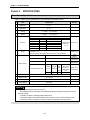
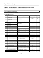
General Specifications
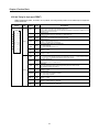
Table 2.1 shows the general specifications of GLOFA GM series and MASTER-K series.
No
Items
Specifications
Operating ambient
temperature
Storage ambient
temperature
Operating ambient
humidity
Storage ambient
humidity
1
2
3
4
5
Vibration
6
Shocks
7
0 ~ 55℃
-25 ~ 75℃
5 ~ 95%RH, non-condensing
5 ~ 95%RH,
non-condensing
Occasional vibration
Acceleration
Amplitude
Sweep count
0.075 mm
9.8㎨ {1G}
10 times in each
Continuous vibration
direction for
Frequency
Acceleration
Amplitude
X, Y, Z
0.035 mm
10≤f∠57 Hz
57≤f≤150 Hz 4.9㎨ {0.5G}
*Maximum shock acceleration: 147 ㎨ {15G}
*Duration time :11 ms
*Pulse wave: half sine wave pulse( 3 times in each of X, Y and Z directions )
Frequency
10≤f∠57 Hz
57 ≤f≤150 Hz
Square wave impulse noise
±1,500 V
Electrostatic discharge
Voltage :4kV(contact discharge)
Radiated electromagnetic field
27 ~ 500 MHz, 10 V/m
Noise immunity
Severity
Level
Fast transient burst noise
Digital
Digital I/Os
I/Os
(Ue < 24 V)
All power
( Ue
Analog I/Os
modules
≥
communication
24 V)
I/Os
Voltage
8 Operating atmosphere
Standard
2 kV
1 kV
IEC 61131-2
IEC 61131-2
LGIS
Standard
IEC 61131-2
IEC1000-4-2
IEC 61131-2
IEC 1000-4-3
IEC 61131-2
IEC1000-4-4
0.25 kV
Free from corrosive gases and excessive dust
9
Altitude for use
Up to 2,000m
10
Pollution degree
2 or lower
11
Cooling method
Self-cooling
[Table 2.1 ] General specifications
REMARK
1) IEC(International Electrotechnical Commission)
: The international civilian organization which produces standards for electrical and electronics industry.
2) Pollution degree
: It indicates a standard of operating ambient pollution level.
The pollution degree 2 means the condition in which normally, only non-conductive pollution occurs.
Occasionally, however, a temporary conductivity caused by condensation shall be expected.
2-1
Chapter 2. SPECIFICATIONS
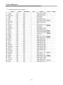
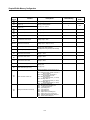
2.2
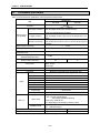
Performance Specifications
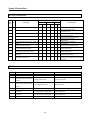
Table. 2.2 shows performance specifications of the high speed PID control module.
Specification
Item
G3F-PIDB
G4F-PIDB
I/O Points
16 Points
0.01 ~ 100.00[%]
Proportional constant (P) (When the integral and derivative constants are set to
0.0 sec, the proportional action is applied.)
0.0
~ 3000.0 sec
Setting range of
Integral
constant
(I)
(When
the integral constant is set to 0.0 sec, the integral action is not
PID constants
applied.)
0.0 ~ 3000.0 sec
Derivative constant (D) (When the derivative constant is set to 0.0 sec, the derivative action is
not applied.)
0 ~ 16,000
Setting range: SV (Set Value)
Input range: PV (Process Value)
0 ~ 16,000
Output range: MV
(Manipulated Value)
0 ~ 16,000
Setting range: M_MV
(Manually Manipulated value)
0 ~ 16,000
Number of PID control loops
32
PID Control (Auto-tuning function)
ON/OFF Control
Manual output
0.01~99.99 sec
Control action
Control cycle
Control type
Output
Type
Measured value derivative type (Pre-derivative type)
Open Collector (Sink type)
Points
Output control cycle
Rated load voltage
Voltage range
Maximum load current
Response time
Common type
1 ~ 100 sec
DC12/24V
DC10.2~26.4V
0.1A/1 point, 1.5A/1 COM
2㎳
16point/1COM
Minimum pulse output
LED 표시
16
RUN / STOP
NORMAL/ERROR
Internal current consumption
Weight
1 ㎳(1/1000:1 ㎳ unit output)
▶ stop : RUN LED Off
▶ Run : Run LEDÆ RUN LED On
Output displayÆRUN LED flickering
▶Auto- tuning : RUN LED On
Run or Output display are selecting by switch on product
Normal: RUN LED ON
Error: RUN LED flickering
0.7 A
510 g
[Table 2.2 ] Performance specifications
2-2
0.6 A
300 g
Chapter 2. SPECIFICATIONS
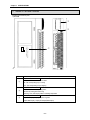
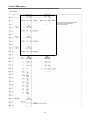
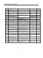
2.3 Names of Parts and Functions
Following gives names of parts.
1)G3F-PIDB
①
RUN
↑
↓
OUTPUT STATE DISPLAY
LOOP STATE DISPLAY
No.
①
③
Descriptions
Loop Run LED
It shows the PID control module run status.
ON : The corresponding loop is running
OFF : The corresponding loop is stopping
RUN LED
②
It shows the PID module Operating status..
ON: Normal, Running the Auto-tuning
Flickering : Error ,LED display switch is selecting output state
LED display switch
③
Loop State Display : Display Loop Running state
Output State Display : Display TR Output(PWM Output)
2-3
②
Chapter 2. SPECIFICATIONS
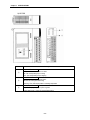
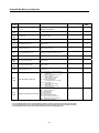
2)G4F-PIDB
No.
①
②
Descriptions
Loop Run LED
It shows the PID control module run status.
ON : The corresponding loop is running
OFF : The corresponding loop is stopping
RUN LED
It shows the PID module Operating status..
ON: Normal, Running the Auto-tuning
Flickering : Error ,LED display switch is selecting output state
LED display switch
③
Loop State Display : Display Loop Running state
Output State Display : Display TR Output(PWM Output)
2-4
Chapter 2. SPECIFICATIONS
2.4
PID Control Action
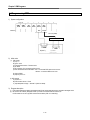
2.4.1 Processing type
1) Velocity type
Velocity type is a processing that in PID processing, the process Manipulated Value(MV) is obtained by
adding the calculated variation of MV (ΔMV) to the previous MV
MVn =
MVn-1 + Δ MVn
MVn
:
Present Manipulated Value
MVn-1
:
Previous Manipulated Value
Δ MVn :
Variation of the Previous Manipulated Value
2) Measured Value Derivative Type (Pre-derivative)
Measured value derivative processing, in PID processing, uses the process value(PV) for the derivative term.
Generally, PID processing, when a deviation occurs, operates toward the direction in which the deviation will
be reduced.
The deviation occurs due to alteration of set value(SV) or outside disturbances. Therefore, if the deviation is
used in the derivative processing, the output of the derivative term changes rapidly when the deviation occur
due to alteration of set value (SV). So, to prevent raid changes like that, this processing uses the process
value(PV) for the derivative term.
MVn =
MVn-1 + Kp 5 (En−En-1) + Kp5S/KI 5En
+ Kp5Kd/S5(2PVn −PVn-1 −PVn-2)
MVn
: Manipulated Value
MVn-1
: Previous Manipulated Value
Δ MVn
En
En-1
Kp
Ki
Kd
S
PVn
PVn-1
PVn-2
:
:
:
:
:
:
:
:
:
:
Variation of the Previous Manipulated Value
present Deviation
Previous Deviation
Proportional Constant
Integral Constant
Derivative Constant
Control Cycle (100ms)
present Process Value
One-step previous Process Value
Two-step previous Process Value
2-5
Chapter 2. SPECIFICATIONS
2.4.2 Control Action
1) Proportional Action (P Action)
(1) P action means a control action that obtains a MV which is proportional to the deviation (E: the difference
between SV and PV).
(2) The expression which denotes the change relationship of E to MV in P action is shown as follows:
MV = Kp×E
where Kp is a proportional constant and means gain.
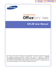
(3) When deviation occurs, the MV by P action is shown in Fig. 2.1.
[Fig. 2.1]
MV with the proportional action
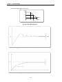
(4) As shown in Fig. 2.1, the larger the proportional constant Kp the larger the MV, that is, the stronger the P
action when the deviation(E) is same . Also, the smaller the Kp the smaller the MV after P action.
(5) If the Kp is too large, PV reaches SV swiftly but can make bad effects like oscillations shown in Fig. 2.3
and cause damage in control stability.
(6) If the Kp is too small, oscillations do not occur but the velocity with which PV reaches SV slows down and
offset can happen as shown in Fig. 2.4.
(7) Manipulated Value varies within 0 to 16,000.
2-6
Chapter 2. SPECIFICATIONS
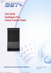
(8) P action MV Output graph for forward action
MV
100%
50%
0%
PV
SV
[Fig. 2.2] P Action MV output graph
[Fig. 2.3] When the proportional constant Kp is large.
[Fig. 2.4] When the proportional constant Kp is small.
2-7
Chapter 2. SPECIFICATIONS
2) Integral Action (I Aaction)
(1) When a deviation(E) occurs between SV and PV, Integral action continuously adds the deviation to or
subtracts it from the MV in accordance time in order to eliminate the deviation
When a deviation is small it is not expected that the MV will be changed by P action but I action will
eliminate it.
Therefore, the offset which occurs in P action can be eliminated by I action.
(2) The period of the time from when the deviation has occurred in I action to when the MV of I action become
that of P action is called Integration time and represented as Ki.
(3) Integral action when a given deviation has occurred is shown as the following Fig. 2.5.
MV
MV of P action
[Fig. 2.5]
Integral action at a constant deviation
(4) Expression of Integral Action is as follows:
As shown in the expression, Integral action can be made stronger or weaker by adjusting integration time
(Ki) in I action.
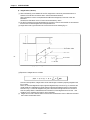
That is, the more the integration time (the longer the integration time) as shown in Fig. 2.6, the lesser the
quantity added to or subtracted from the MV and the longer the time needed for the PV to reach the SV.
As shown in Fig. 2.7, when the integration time given is short the PV will approach the SV in short time
since the quantity added or subtracted become increased. But, If the integration time is too short then
oscillations occurs, therefore, the proper P.I value is requested.
(5) Integral action is used in either PI action in which P action combines with I action or PID action in which P
and D actions combine with I action.
2-8
Chapter 2. SPECIFICATIONS
Set Value
[Fig. 2.5] When a long integration time is given.
[Fig. 2.6] When a short integration time is given.
2-9
Chapter 2. SPECIFICATIONS
3) Derivative Action (D Action)
(1) When a deviation occurs due to alteration of SV or external disturbances, D action restrains the changes of
the deviation by producing MV which is proportioned with the change velocity (a velocity whose deviation
changes at every constant interval) in order to eliminate the deviation.
4D action gives quick response to control action and has an effect to reduce swiftly the deviation by
applying a large control action (in the direction that the deviation will be eliminated) at the earlier time
that the deviation occurs.
4D action can prevent the large changes of control object due to external conditions.
(2) The period of time from when the deviation has occurred to when the MV of D action become the MV of P
action is called derivative time and represented as Kd.
(3) The D action when a given deviation occurred is shown as Fig. 2.8
[Fig. 2.8] Derivative action at a constant deviation
(4) The expression of D action is represented as follows:
4In this expression, an output proportional with the variation rate of deviation is added to P action quantity.
4If the derivative time is increased then P action is strengthened.
4D action is applied when a change of deviation occurs and the deviation at normal state become 0. D
action, therefore, do not reduce offset.
(5) D action is used in either PD action in which P action combines with D action or PID action in which P and I
actions combine with D action.
2 - 10
Chapter 2. SPECIFICATIONS
4) PID Action
(1) PID action controls the control object with the manipulation quantity produced by (P+I+D) action.
(2) PID action when a given deviation has occurred is shown as the following Fig. 2.9
[Fig. 2.9] PID action at a constant deviation
5) PID Processing Expression
PID expressions are of measured value derivative type.
Expressions
MVn
MVn-1
En
En-1
Kp
Ki
Kd
S
PVn
PVn-1
En = SV − PVn
MVn = MVn-1 + Kp × (En−En-1)
+ Kp×S/Ki ×En
+ Kp×Kd/S×(2PVn-1 −PVn −PVn-2)
PVn-2
2 - 11
Parameters names
: Present Manipulated Value
: One-step-previous
Manipulated Value
: Process deviation
: Previous deviation
: Proportional constant
: Integral constant
: Derivative constant
: Control cycle (100 ms)
: Process value
: One-step-previous
Process Value
: Two-step-previous
Process value
Chapter 2. SPECIFICATIONS
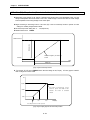
6) Forward/Reverse Actions
(1) PID control has two kinds of action, forward action and reverse action.
a) Forward action makes PV reach SV by outputting MV when PV is less than SV.
b) Reverse action makes PV reach SV by outputting MV when PV is more than SV.
(2) A diagram in which forward and reverse actions are drawn using MV, PV and SV is shown as Fig. 2.10
Forward action
Reverse action
[Fig. 2.10] Forward and reverse action with MV, PV and SV
(3) Fig 2.11 shows examples of process control by forward and reverse actions, respectively.
[Fig. 2.11] Examples of process control by forward and reverse actions
2 - 12
Chapter 2. SPECIFICATIONS
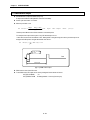
2.5
Auto-tuning
2.5.1 Auto-Tuning block Diagram
▶Appropriate P, I, D constant shall be set to perform optimal control when PID control is applied. The function to
find these parameters automatically is called Auto-Tuning.
▶If Auto-Tuning command starts, PID control module stops PID calculation and moves to start Auto-Tuning.
PID Control
MV
SV
Control
Objects
e
+
Tuning
PV
[Fig 2.12] Auto-Tuning block diagram
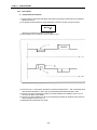
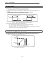
2.5.2 Sequence of Auto-Tuning
▶Relay control method is applied to Auto-Tuning in PID module, which finds and selects P, I, D constant value of
itself while watching the transition of the object to control using relay output.
(1) Forward action (if PV<SV)
PV(Process value)
Tuning set value high limit
sv
Tuning set value low limit
MV(Manipulate value)
100%
Time
0%
Auto-Tuning time(two cycles)
Stage1
PID Control
Stage3
Stage2
[Fig1.13] Auto-Tuning Algorithm for Forward action
2 - 13
Chapter 2. SPECIFICATIONS
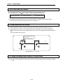
2) Reverse action (if PV<SV)
PV(Process value)
Tuning set value high limit
SV
Tuning set value low limit
MV(Manipulate value)
100%
Time
0%
Auto-Tuning time(two cycles)
Stage1
PID Control
Stage3
Stage2
[Fig1.14] Auto-Tuning Algorithm for Reverse action
Stage 1) Distinction of forward/reverse
▶By comparison between Process value(PV) and Tuning setting value(Set value:SV)
Forward : if the process value is lower than the tuning setting value
Reverse : if the process value is higher than the tuning setting value
Stage 2) Auto-tuning operation
Forward : Manipulated value is repeatedly output 2 cycles in order of min.(0% : 0) to max.(100% : 16000).
Reverse : Manipulated value is repeatedly output 2 cycles in order of max.(100% : 16000) to min.(0% : 0).
▶If auto-tuning operation is complete as repeated as above, output variable END of auto-tuning value Read
function block( PIDBAAT, PIDBAT) changes “0 ⇒ 1”.
Thus, when output variable END of auto-tuning value Read function block changes “0 ⇒ 1” in program, P,
I, D constant value shall be moved to input variable P, I, D of module initializing function block ( PIDBAINI,
PIDBINI)
Stage 3) PID calculation
2 - 14
Chapter 2. SPECIFICATIONS
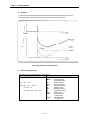
2.6 Set Value(SV) – Ramp function (Set value inclination function)
▶Manipulated value changes by the change of difference the present value to the Manipulated value or by the
change of Manipulated value if PID control is used. Thus, sudden change of the set value leads to sudden change
of the manipulated value causing damage on the control object.
▶Staged increasing or decreasing function of set value (SV) is the set value-ramp function to prevent set value
setting from suddenly changed when modified.
▶Set value-ramp function setting time: 0 ∼ 65,535(Unit:sec)
▶Related function block: PIDBINI
Modified set value
Sudden change
Set value changed by set value-ramp
function
Set value
Time
Setting time
[Fig1.15] Set value ramp function
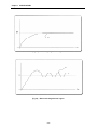
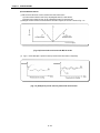
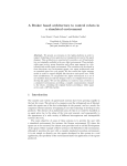
▶ For example, SV_UP value of PIDBINI function block are setting 100 sec, Display SV value graph for Initial SV
value is change from 1000 to 10000
SV
10000
SV value is increasing every
control cycle and then after
100sec. SV value is reached
10000
5500
1000
0
50
100
Time(sec)
SV ramp function start point
[Fig1.16] SV output graph for set value ramp function
2 - 15
Chapter 2. SPECIFICATIONS
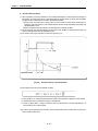
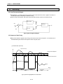
2.7 PWM control output
▶ PID Module has Tr output for PWM in every loop.
Tr output drives SSR for PWM (ON/OFF Control for Pulse width)
▶ Control cycle varies within 1 to 100sec
▶ Minimum pulse time is 1ms
ON
time (㎳ ) =
Output
Range (1000 )
× MV
MV Range (16000 )
output
value × Output
control
cycle ( S )
However pulse ON time round off the numbers to one decimal place
For example if the output control cycle is 1sec, MV 200 the output is 12.5.
In this case On time is 3ms and 987ms is OFF. Although MV is changed during the control cycle the output is not
changed and PWM pulse is changed with the MV of the next 1s.
ON
time (㎳ ) = 1
On
16
× 200 × 1( S ) = 12 . 5
On time is larger
than 1 ms
Time
Off
Output
Control cycle
[Fig1.17] PWM Control output
▶ PWM control is one of the PID control.
▶ To use PWM control,TR output can be used by setting the function blocks as follows..
OUT_EN of PIDBINI
Æ1
OUT_PERD of PIDINI Æ Setting between 1~100 sec,(Control cycle)
2 - 16
Chapter 2. SPECIFICATIONS
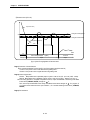
2.8 ON/OFF Control
▶ ON/OFF control is a method controlling the output by comparing SV and MV.
The unchanged output period is used to prevent the rapid variety of the output.
▶ In forward action, if PV is less than SV ON operation is executed and if PV is higher than SV OFF operation is
executed.
During OFF operation,if PV is decreased, MV is repeated ON/OFF near SV.
It makes the operation unstable, the unchanged output period is used to be stable the output.
The unchanged output period
The unchanged output period
ON
ON
OFF
OFF
Reverse
Forward
[Fig1.18] ON/OFF control by setting the The unchanged output period.
Example)When SV is 8000 in the forward action and ONOFF_HYS is 100.
If PV is increased and higher than 8000, the output is OFF and the cooling is processed.
If PV is less than 7900, the output is ON and the heating is processed.
Like the above, ON/OFF is not run between 7900~8000 and ON/OFF is run when the PV is out of the
value(7900~8000). This area is called the unchanged output period.
2.9 Manipulated value upper/Lower LIMIT function
▶ The MV upper/lower limit function is executed with the default value(upper:16000,lower:0) although it’s not set.
▶ If MV_HIGH is set at 12000 and MV_LOW 4000, MV is out 4000 when MV is less than 4000, 12000 when MV is
higher than 12000, and if MV is 4000~12000 the same value is out.
Output
MV_HIGH
(12000)
MV_LOW 0
(4000)
12000 이상
영역
4000 이하
영역
4000
12000
[Fig1.19] MV value upper/lower limit
2 - 17
16000
Input
Chapter 2. SPECIFICATIONS
2.10 MV value output limit function
▶ MV value output limit function is executed with the default value(16000) although it’s not set.
▶ When DELTA_MV is 12000, Δ MVn is limited by 12000 according the following equation.
MVn (MV output value) = MVn-1 (Previous MV value) + Δ MVn(Varied MV value)
▶ According the above equation MV value is out and Δ MVn is limited to 0~16000 to prevent the rapid variation.
But if this value is limited so small, the time to reach at SV is needed more.
2.11 Output upper/lower limit function
▶ Output upper/lower limit function is executed with the default value(upper:1000,lower:0) although it’s not set.
▶ Output upper/lower limit function is used to control PWM output value when MV’s output is used as PWM control.
If PWM control value is less than 200 it PWM is limited at 200, and the value is higher than 800 it PWM is limited at
800.
If MV is 200~800 the same value is out.
When PID output MV Value is 100
,output MV is 200.
On
time
Off
MV
cycle
[Fig1.20] PWM control output
2.12 Change from Manual control mode to PID control mode
▶ When Control mode changes from manual control mode to PID control mode, MV output Value starts manual MV
value.
2 - 18
Chapter 3. INSTALLATION
Chapter 3.
3.1
INSTALLATION
Installation Ambience
This module has high reliability regardless of its installation ambience. But be sure to check the following for
system in higher reliability and stability.
1) Ambience Requirements
Avoid installing this module in locations, which are subjected or exposed to:
- Water leakage and dust a large amount of dust, powder and other conductive power, oil mist, salt, of
organic solvent exists.
- Mechanical vibrations of impacts are transmitted directly to the module body.
- Direct sunlight.
- Dew condensation due to sudden temperature change.
- High or low temperatures (outside the range of 0-55℃)
2) Installing and Wiring
- During wiring or other work, do not allow any wire scraps to enter into the PLC
- Install it on locations that are convenient for operation.
- Make sure that it is not located near high voltage equipment on the same panel.
- Make sure that the distance from the walls of duct and external equipment be 50 mm or more.
- Be sure to be grounded to locations that have good noise immunity.
3.2
Handling Precautions
From unpacking to installing the PID control module, be sure to check the following:
1) Do not drop it off, and make sure that strong impacts should not be applied.
2) Do not dismount printed circuit boards from the case. It can cause malfunctions.
3) During wiring, be sure to check any foreign matter like wire scraps should not enter into the upper side of
the PLC, and in the event that foreign matter entered into it, always eliminate it.
4) Be sure to disconnect electrical power before mounting or dismounting the module.
3- 1
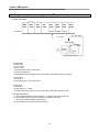
Chapter 3. INSTALLATION
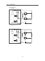
Array of tremial block
1) G3F-PIDB
16/34
Tr0
00/18
Inner
circu
it
L
R
Tr31
15/33
L
R
DC24V
17/35
2) G4F-PIDB
16
Tr0
00
Inner
circu
it
L
R
Tr15
15
L
R
DC24V
17
3- 2
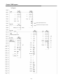
Chapter 4 Function Block
Chapter 4 FUNCTION BLOCK
▶PID control module function blocks used in GMWIN are described below.
NO
1
2
3
4
5
6
G3F-PIDB
PIDBAINI
PIDBINI
PIDBACAL
PIDBCAL
PIDBAAT
PIDBAT
G4F-PIDB
PIDBAINI
PIDBINI
PIDBACAL
PIDBCAL
PIDBAAT
PIDBAT
Description
Module initialization (Array type)
Module initialization (Single type)
PID calculation (Array type)
PID calculation (Single type)
Auto Tuning (Array type)
Auto Tuning (Single type)
Remark
1. To operate PID calculation FB and Auto tuning FB simultaneously causes the malfunction.
2. Array number of 4.2※1 is G3F- PIDB :32, G4F-PIDB: 16.
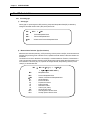
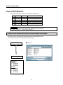
4.1 Insertion of the function blocks for the PID control module on the GMWIN
▶Function blocks can be inserted with the following procedures while the GMWIN is running.
▶ Inserting a function block is only possible when a project is open.
Project (P)
■GMWIN V4.0
Insert Library (I)
G3F-PIDB
1. Special.3fb
2. Remote3.3fb
3. Remote4.3fb
4. Remote6.3fb
G4F-PIDB
1. Special.4fb
2. Remote3.4fb
3. Remote4.4fb
4. Remote6.4fb
4-1
Chapter 4 Function Block
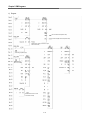
4.2 Function block used in PID control module
4.2.1Module initialization for array type ( PIDBAINI )
Module initialization function block specifies PID control module base location, slot location, run loop enable/disable and
forward/reverse action, and sets MV, M_MV and P.I.D constants for use in program so on.
Function
Block
I/O
Variable
Data
Type
REQ
BOOL
BASE
USINT
SLOT
USINT
LOOP
BOOL
[ARRAY]*1
PERD
UINT
[ARRAY]*1
D/R
BOOL
[ARRAY]*1
UINT
[ARRAY]*1
UINT
[ARRAY]*1
UINT
[ARRAY]*1
PIDBAINI
REQ
DONE
BASE
STAT
SLOT
ACT
LOOP
PERD
D/R
SV__
UP
SV__
DOWN
MV__
LOW
MV__
HIGH
DELT
A_MV
SV_UP
SV_DOWN
MV_LOW
Input
P
MV_HIGH
UINT
[ARRAY]*1
DELTA_MV
UINT
[ARRAY]*1
P
UINT
[ARRAY]*1
I
UINT
[ARRAY]*1
D
UINT
[ARRAY]*1
OUT_EN
BOOL
[ARRAY]*1
OUT_PERD
UINT
[ARRAY]*1
OUT_LOW
UINT
[ARRAY]*1
OUT_HIGH
UINT
[ARRAY]*1
ONOF_HYS
UINT
[ARRAY]*1
DONE
BOOL
STAT
USINT
ACT
BOOL
[ARRAY]*1
I
D
OUT_
EN
OUT_
PERD
OUT_
LOW
OUT_
HIGH
ONOF
_HYS
Output
Descriptions
Function block execution request area
● Used to request an execution of the initialization function block
● If the conditions connected with this area are established while program is running and “0” changes into “1”, the
initialization function block is executed
Base location No.
● Used to write the base No. where the PID control module is mounted.
● Setting range: GM1 series (0~31), GM2 series (0~7), GM3/4 series (0-3)
Slot location No.
● Used to write slot No. where the PID control module is mounted.
● Setting range: 0~7
Run loop enable/disable specification
● Used to enable or disable a loop for run.
● Specify “1” for enabling, and “0” for disabling
Run loop control cycle (0.01 ~ 99.99sec)
● Setting range: 1 ~ 9999
● If this value is not set or set as “0” this value is initialized as “1”.
Forward/Reverse action specification for a run loop.
●Specify “0” for forward action and “1” for reverse action.
Setting a time until a run loop reaches at the target value when the target value rises.
●Setting range: 0~65535sec
Setting a time until a run loop reaches at the target value when the target value falls.
●Setting range: 0~65535sec
Setting the low limit for the run loop
● Setting range: 0 ~ 16000 (The range should be within the high limit) [Refer 2.9]
Setting the high limit for the run loop
●Setting range: 1 ~ 16000 (The range should be within the high limit)
● If this value is not set or set as “0” this value is initialized as “16000”. (Refer 2.9)
Setting for the variable quantity limit of the control value
● Setting range: 1 ~ 16000
● If this value is not set or set as “0” this value is initialized as “16000”. (Refer 2.10)
Setting a proportional constant (0.01 ~ 100.00) for a run loop
●Setting range: 1~10000
● If this value is not set or set as “0” this value is initialized as “1”
Setting an integral constant (0.0 ~3000.0 sec) for a run loop
● Setting range: 0~30000
● Integral action not executed if the integral constant is set to ‘0’.
Setting a derivative constant (0.0 ~3000.0 sec) for a run loop
● Setting range: 0~30000
● Derivative action not executed if the derivative constant is set to ‘0’.
Run roop output enable, disable (Transistor output)
● “0” disable.
● “1” enable.
Run roop output enable/disable set in OUT_EN (1 ~ 100s)
● Setting range: 1 ~ 100
● If this value is not set or set as “0” this value is initialized as “1”
Setting the output low limit of the run roop set in OUT_EN
● Setting range: 0 ~ 16000 (The range should be within the high limit) [Refer 2.11]
Setting the output high limit of the run roop set in OUT_EN
● Setting range: 0 ~ 16000 (The range should be within the high limit) [Refer 2.11]
● If this value is not set or set as “0” this value is initialized as “1”
Setting the run interval for the run roop ON/OFF
● Setting range: 0 ~ 8000 [Refer 2.8]
Function block finished execution status
● “1” is output when the initialization function block is finished with no error and “1” remains until next execution.
If an error occurs, ‘0’ is displayed and the operation enters into the stop state.
Error status indication area
● Used to output the number of an error when it occurs during initialization function block execution.
● For description of errors, see GM Section 6.3
Run loop status indication area
● After the initialization function block is finished with no error, “1” is output if the loop is in normal state. But “0” is
output for the disabled loops.
4-2
Chapter 4 Function Block
4.2.2 Module initialization for single type ( PIDBINI )
Module initialization function block specifies PID control module base location, slot location, run loop enable/disable and
forward/reverse action, and sets MV, M_MV and P.I.D constants for use in program so on.
Function
Block
I/O
Variable
Data
Type
REQ
BOOL
BASE
USINT
SLOT
USINT
LOOP
USINT
PERD
UINT
D/R
BOOL
SV_UP
UINT
SV_DOWN
UINT
MV_LOW
UINT
MV_HIGH
UINT
DELTA_MV
UINT
P
UINT
I
UINT
D
UINT
OUT_EN
BOOL
OUT_PERD
UINT
OUT_LOW
UINT
OUT_HIGH
UINT
ONOF_HYS
UINT
DONE
BOOL
STAT
USINT
PIDBINI
REQ
DONE
BASE
STAT
SLOT
LOOP
PERD
D/R
SV__
UP
SV__
DOWN
MV__
LOW
MV__
HIGH
DELT
A_MV
Input
P
I
D
OUT_
EN
OUT_
PERD
OUT_
LOW
OUT_
HIGH
ONOF
_HYS
Output
Descriptions
Function block execution request area
● Used to request an execution of the initialization function block
● If the conditions connected with this area are established while program is running and “0” changes into “1”, the
initialization function block is executed
Base location No.
● Used to write the base No. where the PID control module is mounted.
● Setting range: GM1 series (0~31), GM2 series (0~7), GM3/4 series (0-3)
Slot location No.
● Used to write slot No. where the PID control module is mounted.
● Setting range: 0~7
Run loop enable/disable specification
● Used to enable or disable a loop for run.
● Specify “1” for enabling, and “0” for disabling
Run loop control cycle (0.01 ~ 99.99sec)
● Setting range: 1 ~ 9999
● If this value is not set or set as “0” this value is initialized as “1”.
Forward/Reverse action specification for a run loop.
●Specify “0” for forward action and “1” for reverse action.
Setting a time until a run loop reaches at the target value when the target value rises.
●Setting range: 0~65535sec
Setting a time until a run loop reaches at the target value when the target value falls.
●Setting range: 0~65535sec
Setting the low limit for the run loop
● Setting range: 0 ~ 16000 (The range should be within the high limit) [Refer 2.9]
Setting the high limit for the run loop
●Setting range: 1 ~ 16000 (The range should be within the high limit)
● If this value is not set or set as “0” this value is initialized as “16000”. (Refer 2.9)
Setting for the variable quantity limit of the control value
● Setting range: 1 ~ 16000
● If this value is not set or set as “0” this value is initialized as “16000”. (Refer 2.10)
Setting a proportional constant (0.01 ~ 100.00) for a run loop
●Setting range: 1~10000
● If this value is not set or set as “0” this value is initialized as “1”
Setting an integral constant (0.0 ~3000.0 sec) for a run loop
● Setting range: 0~30000
● Integral action not executed if the integral constant is set to ‘0’.
Setting a derivative constant (0.0 ~3000.0 sec) for a run loop
● Setting range: 0~30000
● Derivative action not executed if the derivative constant is set to ‘0’.
Run roop output enable, disable (Transistor output)
● “0” disable.
● “1” enable.
Run roop output enable/disable set in OUT_EN (1 ~ 100s)
● Setting range: 1 ~ 100
● If this value is not set or set as “0” this value is initialized as “1”
Setting the output low limit of the run roop set in OUT_EN
● Setting range: 0 ~ 16000 (The range should be within the high limit) [Refer 2.11]
Setting the output high limit of the run roop set in OUT_EN
● Setting range: 0 ~ 16000 (The range should be within the high limit) [Refer 2.11]
● If this value is not set or set as “0” this value is initialized as “1”
Setting the run interval for the run roop ON/OFF
● Setting range: 0 ~ 8000 [Refer 2.8]
Function block finished execution status
● “1” is output when the initialization function block is finished with no error and “1” remains until next execution.
If an error occurs, ‘0’ is displayed and the operation enters into the stop state.
Error status indication area
● Used to output the number of an error when it occurs during initialization function block execution.
● For description of errors, see GM Section 6.3
4-3
Chapter 4 Function Block
4.2.3 Controlling calculation for array type ( PIDBACAL )
PIDBACAL control PID whole loops and specifies ON/OFF enable or disable, auto/manual run enable or disable, manually controlled value,
target value and current value, PID calculated value etc.
Function
Block
I/O
PIDBACAL
REQ
DONE
BASE
STAT
SLOT
ALM
LOOP
ACT
ON__
OFF
MV
A_M SV_C
AL
MAN_ OUT_
CAL
MV
Variable
Data
Type
Descriptions
REQ
BOOL
Function block execution request area
● Used to request an execution of the initialization function block
● If the conditions connected with this area are established while program is running and “0” changes into “1”, the
initialization function block is executed
BASE
USINT
Base location No.
● Used to write the base No. where the PID control module is mounted.
● Setting range: GM1 series (0~31), GM2 series (0~7), GM3/4 series (0-3)
SLOT
USINT
LOOP
BOOL
[ARRAY]*1
ON_OFF
BOOL
[ARRAY]*1
A_M
BOOL
[ARRAY]*1
Input
SV
PV
MAN_MV
SV
PV
Output
INT
[ARRAY]*1
INT
[ARRAY]*1
INT
[ARRAY]*1
Slot location No.
● Used to write slot No. where the PID control module is mounted.
● Setting range: 0~7
Run loop enable/disable specification
● Used to enable or disable a loop for run.
● Specify “1” for enabling, and “0” for disabling
ON/OFF control enable/ disable for the run loop.
● “0”: ON/OFF control enable.
● “1”: ON/OFF control disable.
Auto/Manual control enable/ disable for the run loop.
● “0”: Auto-calculation selection.
● “1”: Manual control selection.
Manual control value for the run loop.
● Range : 0 ∼ 16000
Target value for the run loop.
● Range: 0 ~ 16000
Current value for the run loop.
● Range: 0 ~ 16000
Function block finished execution status
● “1” is output when the initialization function block is finished with no error and “1” remains until next execution.
If an error occurs, ‘0’ is displayed and the operation enters into the stop state.
Error status indication area
● Used to output the number of an error when it occurs during initialization function block execution.
● For description of errors, see GM Section 6.3
DONE
BOOL
STAT
USINT
ALM
USINT
[ARRAY]*1
Alarm status
● If an alarm happened the alarm number is displayed during the function block execution.
●For description of alarms, see section 4.4.
ACT
BOOL
[ARRAY]*1
● After the initialization function block is finished with no error, “1” is output if the loop is in normal state. But “0” is
MV
INT
[ARRAY]*1
● Range: 0 ~ 16000
SV_CAL
INT
[ARRAY]*1
Calculated SV value for the enabled run loops.
● Range: 0 ~ 16000
OUT_CAL
INT
[ARRAY]*1
Output value for the enabled run loops (0.0 ~ 100.0%)
● PWM range: 0 ~ 1000
Run loop status indication area
output for the disabled loops.
MV data for the enabled run loops
4-4
Chapter 4 Function Block
4.2.4 Controlling calculation for single type ( PIDBCAL )
PIDBCAL control PID whole loops and specifies ON/OFF enable or disable, auto/manual run enable or disable, manually controlled value,
target value and current value, PID calculated value etc.
Function
Block
I/O
PIDBCAL
REQ
DONE
BASE
STAT
SLOT
ALM
LOOP
MV
ON__
OFF
SV_C
AL
OUT_
CAL
A_M
MAN_
MV
Variable
Data
Type
Descriptions
REQ
BOOL
Function block execution request area
● Used to request an execution of the initialization function block
● If the conditions connected with this area are established while program is running and “0” changes into “1”, the
initialization function block is executed
BASE
USINT
Base location No.
● Used to write the base No. where the PID control module is mounted.
● Setting range: GM1 series (0~31), GM2 series (0~7), GM3/4 series (0-3)
SLOT
USINT
LOOP
USINT
ON_OFF
BOOL
A_M
BOOL
MAN_MV
INT
SV
INT
PV
INT
DONE
BOOL
STAT
USINT
ALM
USINT
MV
INT
SV_CAL
INT
Calculated SV value for the enabled run loops.
● Range: 0 ~ 16000
OUT_CAL
INT
Output value for the enabled run loops (0.0 ~ 100.0%)
● PWM range: 0 ~ 1000
Input
SV
PV
Output
Slot location No.
● Used to write slot No. where the PID control module is mounted.
● Setting range: 0~7
Run loop enable/disable specification
● Used to enable or disable a loop for run.
● Specify “1” for enabling, and “0” for disabling
ON/OFF control enable/ disable for the run loop.
● “0”: ON/OFF control enable.
● “1”: ON/OFF control disable.
Auto/Manual control enable/ disable for the run loop.
● “0”: Auto-calculation selection.
● “1”: Manual control selection.
Manual control value for the run loop.
● Range : 0 ∼ 16000
Target value for the run loop.
● Range: 0 ~ 16000
Current value for the run loop.
● Range: 0 ~ 16000
Function block finished execution status
● “1” is output when the initialization function block is finished with no error and “1” remains until next execution.
If an error occurs, ‘0’ is displayed and the operation enters into the stop state.
Error status indication area
● Used to output the number of an error when it occurs during initialization function block execution.
● For description of errors, see GM Section 6.3
Alarm status
● If an alarm happened the alarm number is displayed during the function block execution.
●For description of alarms, see section 4.4.
MV data for the enabled run loops
● Range: 0 ~ 16000
4-5
Chapter 4 Function Block
4.2.5 Auto Tuning for array type ( PIDBAAT )
PIDBAAT specifies base number, slot number, run loop selection, auto tuning start/stop selection for the enabled loop and displays MV,
and auto-tuned value.
Function
Block
I/O
PIDBAAT
REQ
DONE
BASE
STAT
SLOT
ALM
LOOP
ACT
AUTO
TUNE
MV
SV
TUNE
_END
PV
TUNE
_P
Input
Variable
Data
Type
REQ
BOOL
BASE
USINT
SLOT
USINT
LOOP
BOOL
[ARRAY]*1
AUTO
TUNE
SV
TUNE
_I
TUNE
_D
PV
Descriptions
Function block execution request area
● Used to request an execution of the initialization function block
● If the conditions connected with this area are established while program is running and “0” changes into “1”, the
initialization function block is executed
Base location No.
● Used to write the base No. where the PID control module is mounted.
● Setting range: GM1 series (0~31), GM2 series (0~7), GM3/4 series (0-3)
Slot location No.
● Used to write slot No. where the PID control module is mounted.
● Setting range: 0~7
Run loop enable/disable specification
● Used to enable or disable a loop for run.
● Specify “1” for enabling, and “0” for disabling
Auto tuning start/stop selection for the enabled loops.
BOOL
● “0”: Auto Tuning stop.
[ARRAY]*1
● “1”: Auto Tuning start [See section 2.5.2]
INT
Target value for the run loops.
[ARRAY]*1 ● Range: 0 ~ 16000
INT
Current value for the run loops.
[ARRAY]*1 ● Range: 0 ~ 16000
Function block finished execution status
● “1” is output when the initialization function block is finished with no error and “1” remains until next execution.
If an error occurs, ‘0’ is displayed and the operation enters into the stop state.
Error status indication area
● Used to output the number of an error when it occurs during initialization function block execution.
● For description of errors, see GM Section 6.3
DONE
BOOL
STAT
USINT
ALM
USINT
[ARRAY]*1
ACT
BOOL
● After the initialization function block is finished with no error, “1” is output if the loop is in normal state. But “0” is
[ARRAY]*1
MV
INT
[ARRAY]*1
TUNE_END
BOOL
[ARRAY]*1
Alarm status
● If an alarm happened the alarm number is displayed during the function block execution.
●For description of alarms, see section 4.4.
Run loop status indication area
Output
output for the disabled loops.
TUNE_P
TUNE_I
TUNE_D
UINT
[ARRAY]*1
UINT
[ARRAY]*1
MV data for the enabled run loops
● Range: 0 ~ 16000
Auto Tuning status.
● “0”: Auto Tuning is not completed or canceled.
● “1”: Auto Tuning is completed.
P value obtained by Auto Tuning.
● Range: 1 ~ 10000
I value obtained by Auto Tuning.
● Range: 0 ~ 30000 (I value: 0.0 ~ 3000.0 sec)
UINT
D value obtained by Auto Tuning.
[ARRAY]*1 ● Range: 0 ~ 30000 (D value: 0.0 ~ 3000.0 sec)
4-6
Chapter 4 Function Block
4.2.6 Auto Tuning for single type ( PIDBAT )
PIDBAT specifies base number, slot number, run loop selection, auto tuning start/stop selection for the enabled loop and displays MV,
and auto-tuned value.
Function
Block
I/O
PIDBAT
REQ
DONE
BASE
STAT
SLOT
ALM
LOOP
MV
Input
AUTO TUNE
TUNE _END
SV
TUNE
_P
PV
TUNE
_I
TUNE
_D
Output
Variable
Data
Type
REQ
BOOL
BASE
USINT
SLOT
USINT
LOOP
USINT
AUTO
TUNE
BOOL
SV
INT
PV
INT
DONE
BOOL
STAT
USINT
ALM
USINT
MV
INT
TUNE_END
BOOL
TUNE_P
UINT
TUNE_I
UINT
TUNE_D
UINT
Descriptions
Function block execution request area
● Used to request an execution of the initialization function block
● If the conditions connected with this area are established while program is running and “0” changes into “1”, the
initialization function block is executed
Base location No.
● Used to write the base No. where the PID control module is mounted.
● Setting range: GM1 series (0~31), GM2 series (0~7), GM3/4 series (0-3)
Slot location No.
● Used to write slot No. where the PID control module is mounted.
● Setting range: 0~7
Run loop enable/disable specification
● Used to enable or disable a loop for run.
● Specify “1” for enabling, and “0” for disabling
Auto tuning start/stop selection for the enabled loops.
● “0”: Auto Tuning stop.
● “1”: Auto Tuning start [See section 2.5.2]
Target value for the run loop.
● Range: 0 ~ 16000
Current value for the run loop.
● Range: 0 ~ 16000
Function block finished execution status
● “1” is output when the initialization function block is finished with no error and “1” remains until next execution.
If an error occurs, ‘0’ is displayed and the operation enters into the stop state.
Error status indication area
● Used to output the number of an error when it occurs during initialization function block execution.
● For description of errors, see GM Section 6.3
Alarm status
● If an alarm happened the alarm number is displayed during the function block execution.
●For description of alarms, see section 4.4.
MV data for the enabled run loop.
● Range: 0 ~ 16000
Auto Tuning status.
● “0”: Auto Tuning is not completed or canceled.
● “1”: Auto Tuning is completed.
P value obtained by Auto Tuning.
● Range: 1 ~ 10000
I value obtained by Auto Tuning.
● Range: 0 ~ 30000 (I value: 0.0 ~ 3000.0 sec)
D value obtained by Auto Tuning.
● Range: 0 ~ 30000 (D value: 0.0 ~ 3000.0 sec)
4-7
Chapter 4 Function Block
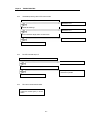
4.3 Errors on function block
Errors indicated by an output variable STAT and their corrective actions are explained.
Function block
STAT
Item
No.
Initialization
Descriptions
Array
0
Single
Calculation
Corrective Action
Auto Tuning
Array Single Array Single
-
Normal Run status
Adjust it within the setting range
(See Section 4.2, 4.3)
Base location No. outside the setting range
2
The corresponding base module hardware defect
О
О
О
О
О
О
Contact a service station
3
Slot location No. outside the setting range
О
О
О
О
О
О
4
The specified slot has no PID control module
О
О
О
О
О
О
5
A module other than the PID control module is
Local loaded on.
О
О
О
О
О
О
Specify correctly the slot No.
where the PID control module is mounted.
Mount the PID control module on
the specified slot.
Mount the PID control module on
the specified slot.
-
О
-
О
Specify correctly the No. of the run loop.
6
Loop No. outside the setting range
7
PID control Module hardware Defect
О
О
О
О
О
О
Contact a service station.
8
PID control module shared memory defect
О
О
О
О
О
О
Contact a service station.
9
The run loop was not specified in the Initialization
function block.
-
-
О
О
О
О
10
Inputs outside the setting range
О
О
О
О
О
О
Specify correctly run loops in
the initialization function block.
One or more of SV, M_MV, P, I, D and PV outside
the setting range, adjust it/them within its/their
setting range.
4.4 Alarms on function block
ALM No.
0
1
2
Description
Normal Run status
Auto Tuning execution during ON/OFF
operation.
ON/OFF operation during Auto Tuning
execution.
Run status
Corrective Action
Normal run
-
ON/OFF operation executed.
Stop Auto Tuning operation.
Auto Tuning operation executed.
Stop ON/OFF operation.
3
SV change during Auto Tuning
Run with the SV value before changing.
The alarm is executed only during Auto Tuning.
4
SV value over
Run with Low limit (0) or High limit (16000)
Specify correctly the value.
5
PV value over
Run with Low limit (0) or High limit (16000)
Specify correctly the value.
6
MV value over
Run with Low limit (0) or High limit (16000)
Specify correctly the value.
4-8
Chapter 5 GM Programs
Chapter5 GM PROGRAMS
5.1
Program example using G3F-AD4B module
1) System configuration
0
SLOT NO.
GM3PA1A
GM3CPUA
G3ID24A
1
2
G3ID24A
G3FAD4B
Ch0
GM3-B06M
3
G3FPIDB
Loop0
4
5
G3FDA4I
G3QRY4A
Ch0
BCD digital switch
(%I0.0.0~%I0.0.19)
P value setting
(%I0.1.0)
I value setting
(150℃)
(%I0.1.1)
D value setting
(%I0.1.2)
(%I0.1.3)
2) Initial value
(1) PID module
A) Used loop : Loop 0
B) Control cycle : 10ms
C) Forward, reverse action : Forward action
D) SV value : 12000
E) Auto/Manual calculation selection : Auto calculation
F) Initial PID constants : P=200,I=500,D=500
(2) A/D module
A) Channel : 0
B) Output data type : 0 ~ 16000
C) Average calculation : 20 times
D) Signal converter specification : Input 0~200℃, Output 4~20mA
(3) D/A module
A) Channel : 0
B) Input data type selection : -192 ~ 16191
C) Output status when a channel is not used or CPU stops : Mid-value of the output range.
3) Program descriptions
A)Temperature 0 ~ 200°C from sensor is transferred to 4 ~ 20 mA and the current is input to A/D module to convert to
digital value.
B) 150°C(The signal converter’s output is 16mA, Target value 12000) is set with MV value in PID and P,I,D constants are
controlled with the initialized value.
If %I0.1.0 is On the modified value by BCD switch is set with MV.
If %I0.1.1 is On the modified value by BCD switch is set with I.
If %I0.1.2 is On the modified value by BCD switch is set with D.
C)PID calculated value is output on D/A module’s channel 0.
D)If %I0.1.3 is On A/D,PID,D/A modules are initialized.
5- 1
Chapter 5 GM Programs
4) Signal processing relation with each modules
Sensor’s temperature range : 0 ~ 200 °C
Signal converter’s current output range : DC 4 ~ 20 mA
A/D module’s current input range : DC 4 ~ 20 mA
A/D module’s digital output range : 0 ~ 16000
PID module’s input range : 0 ~ 16000
PID module’s calculated MV range : 0 ~ 16000
D/A module’s digital input range : 0 ~ 16000
D/A module’s output range : DC 4 ~ 20 mA
Electric furnace’s range : 0 ~ 200 °C
5- 2
Chapter 5 GM Programs
5) Program
1.Convert the value which input by BCD switch
to the data type such as PID constants.
2.Input as P,I,D constants.
Move A/D value to PID current value
5- 3
Chapter 5 GM Programs
PID MV value is used as D/A input value
PID MV value is used as D/A input value
5- 4
Chapter 5 GM Programs
6) Input/Output variables used in this program.
Variable name
Data Kind
Memory allocation
Used
5- 5
Data Type
Initial Value
Comments
Chapter 5 GM Programs
5.2
Program using the auto tunning function (TC module used)
1) System configuration
0
SLOT NO.
GM3PA1A
GM3CPUA
G3ID24A
GM3-B06M
1
G3ID24A
2
3
4
5
G3FTC4A
G3FPIDB
G3FDA4I
G3QRY4A
Ch 0
Loop0
Ch 0
BCD 디지털 스위치
200~12000℃
(%I0.0.0~%I0.0.19)
온도센서
비례상수(P)값 설정
(%I0.1.0)
700℃
전기로
히터
(%I0.1.1)
미분상수(D)값 설정
(%I0.1.2)
전력 변환 장치
수동출력 입력설정
(%I0.1.3)
2) Initial value
(1) PID module
A) Loop : Loop 0
B) Cycle : 50ms
C) Forward/reverse action : Forward action
D) MV value : 8000(700℃)
E) Auto/Manual calculation selection : After synchronization, auto operation with P,I,D constants.
(2) A/D module
A) Channel : 0
B) Input sensor type : K TYPE(-200~1200℃)
(3) D/A module
A) Channel : 0
B) Input data type : 0 ~ 16000
C) Output status when a channel is not used or CPU stops : Mid-value of the output range.
2) Program descriptions
(1) The converted temperature value is transferred 0~16000 and input as a current value..
(2) PID is set MV as 700°C and P,I,D constants are calculated by auto-tuning.
PID control is executed with this calculated value.
(3) PID calculated values are output to D/A module’ ch0.
5- 6
Chapter 5 GM Programs
3) Program
2
(Used channel’s temperature value)
(Temperature value is changed to 0~16000)
Auto-tuning completion contact
3
After auto-tuning,
auto-run is executed
5- 7
Chapter 5 GM Programs
(During auto-tuning MV is transferred to D/A module)
(During auto-tuning MV is transferred to D/A module)
4
5- 8
Chapter 5 GM Programs
5) Input/Output variables used in this program.
Variable name
Data Kind
Memory allocation
Used
5- 9
Data Type
Initial Value
Comments
Chapter 5 GM Programs
5.3 Program using PWM
1) System configuration
SLOT NO.
GM3PA1A
GM3CPUA
GM3-B06M
0
G3ID24A
1
G3ID22A
2
3
G3FRD3A
G3FPIDB
Ch0
Loop0
4
5
DC 0~24V(PWM)
BCD 디지털스위치
(%I0.0.0~%I0.0.19)
SSR
비례상수값 설정
%I0.1.0
적분상수값 설정
%I0.1.1
미분상수값 설정
%I0.1.2
RTD
RTD
SV(200℃)
Heater
전기화로
2) Initial value
(1) PID module
A) Loop : 0
B) Cycle : 50ms
C) Forward/reverse action : Forward action
D) SV: 8000
E) PID constants: P,I,D constants by Auto-tuning
F) Auto calculation/manual calculation : Auto – In case that RTD doesn’t have an error.
Manual – In case that RTD has an error.
G) Output :PWM
H) Output cycle:10 ㎳
(2) RTD module
A) Channel : 0
B) RTD module’s sensor : Pt100
C) Input temperature range: - 200~600℃(SCAL:0~16000)
3) Program description
(1) RTD module detects the heater’s temperature with Pt100 and the detected value is changed to the digital value.
(2) MV value is set as 8000( Temperature 200°C) and PID is executed with auto-tuned P,I,D
If PID module has an error (by RTD module’s disconnection) PID is run with SV(0).
5- 10
Chapter 5 GM Programs
4) Program
(The used channel’s temperature value)
(0~16000 changed from the temperature value)
(Digital value(0~16000) of channel 0 is input
as the current value)
(Auto-tuning completion signal)
자기유지 접점
(After auto-tuning
auto-run is executed)
(If RTD module has an error PID
is executed as manual)
5- 11
Chapter 5 GM Programs
5) Input/Output variables used in this program.
Variable name
Data Kind
Memory allocation
Used
5- 12
Data Type
Initial Value
Comments
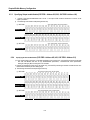
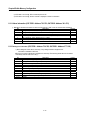
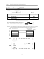
Chapter6 Buffer Memory Configuration
Chapter6 BUFFER MEMORY CONFIGURAGION AND FUNCTIONS
The PID control module has the PLC CPU and the buffer memories for communications.
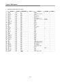
6.1 Buffer memory configuration
The followings describe buffer memory configuration
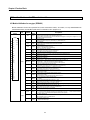
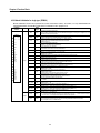
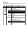
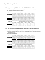
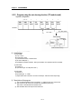
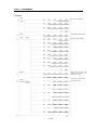
6.1.1 G3F-PIDB Buffer memory
Address
Function
(Decimal)
0
1
2~
33
34
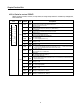
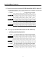
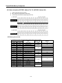
35
36~
67
68~
99
Loop enable/disable
Specification area
(loop 0 to 15)
Loop enable/disable
Specification area
(loop 16 to 31)
Bit On(1): Enabled
Bit Off(0): Disabled
Control cycle of each loop
Range:1~9999 (0.01~99.99 sec)
Forward/Reverse action
Specification area
(loop 0 to 15)
Forward/Reverse action
Specification area
(loop 16 to 31)
Bit On(1): Reverse
Bit Off(0): Forward
SV-ramp of each loop(rising) *1
Default Setting
Read /
Write
Disabled
R/W
10
“
0: Forward
“
0:SV reaching Immediately.
“
0:SV reaching Immediately
“
Setting range :0 to 65535 sec) [See section 2.6]
SV-ramp of each loop(falling) *2
100~
131
MV low limit of each loop
132~
163
MV higher limit of each loop
164~
195
196~
227
228~
259
260~
291
Descriptions
Setting range :0~16000
(It should be set lower than MV higher limit) [See
section 2.9]
Setting range:1~16000
(It should be set higher than MV higher limit) [See
section 2.9]
0
“
16000
“
16000
“
ΔMV Limit of each loop
Setting range:1~16000 [See section 2.10]
P of each loop
Setting range:1~10000
1
“
I of each loop
Setting range:0~30000
0
“
D of each loop
Setting range:0~30000
0
“
0:Disable
“
292
Output enable/ disable (loop 0~15)
293
Output enable/ disable (loop 16~31)
294~
325
Output control cycle of each loop
Setting range :1~100 see
(It should be higher than the loop control cycle)
10
“
326~
357
Output lower limit of each loop
(It should be lower than the upper limit)
Setting range:0~16000 [see section 2.11]
0
“
358~
389
Output upper limit of each loop
(It should be lower than the lower limit)
Setting range:1~16000 [see section 2.11]
16000
“
390~
421
ON/OFF interval of each loop
Setting range:0~8000 [see section 2.8]
100
“
422
SET DATA enable/disable (loop 0~15)
0
“
423
SET DATA enable/disable (loop16~31)
424
425
426
427
ON/OFF enable/disable (loop0~15)
ON/OFF enable/disable (loop16~31)
Auto Tuning enable/ disable (loop 0~15)
Auto Tuning enable/ disable (loop 16~31)
0
“
0
“
Bit On(1):Enable, Bit Off(0):Disable
Bit On(1): Set address 0~421,424~493to a new SV
value
Bit Off(0): Set address 0~421,424~493to a previous
value
Bit On(1):ON/OFF enable
Bit Off(0):ON/OFF disable [see section 2.8]
Bit On(1):Auto Tuning enable
Bit Off(0):Auto Tuning disable [see section 2.5.2]
6- 1
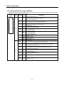
Chapter6 Buffer Memory Configuration
Address
(Decimal)
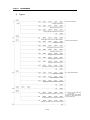
428~
459
Function
Descriptions
Default Setting
Read /
Write
Manual MV of each loop
Setting range :0~16000
0
“
Auto/Manual operation enable/disable
(loop 0~15)
Auto/Manual operation enable/disable
(loop 16~31)
Bit On(1): Manual operation
Bit Off(0):Auto operation
0
R/W
SV of each loop
Setting range :0~16000
0
“
PV of each loop
Setting range :0~16000
0
“
526~
557
MV of each loop
Setting range :0~16000
0
읽기
558~
589
Calculated SV of each loop *3
Setting range :0~16000
-
“
Output value of each loop
Setting range :0~1000(0.0~100.0%)
-
“
Bit On(1):Auto Tuning completion
Bit Off(0):Auto Tuning running or PID controlling
-
“
460
461
462~
493
494~
525
590~621
622
Auto Tuning completion(loop 0~15)
623
Auto Tuning completion(loop 16~31)
624~
655
Auto Tuned P value of each
Range :1~10000
-
“
656~
687
Auto Tuned I value of each
Range :0~30000
-
“
688~
719
Auto Tuned D value of each
Range :0~30000
-
“
720
Status information (loop 0~15)
Bit On(1):Run
Bit Off(0):Stop
-
“
-
“
-
“
721
Status information (loop 16~31)
722~
753
Alarm information of each loop
754~
785
Setting error information of each loop
Bit0 :During ON/OFF, Auto Tuning executed Æ
ON/OFF hold.
Bit1 : During Auto Tuning, ON/OFF command Æ
Auto Tuning hold
Bit2 : During Auto Tuning, SV changed Æ
Run with the previous SV
Bit3 : Manual MV OVER Æ
Run with the limit value ( 0 or 16000)
Bit4 : SV setting OVER Æ
Run with the limit value (0 or 16000)
Bit5 : PV setting OVER Æ
Run with the limit value (0 or 16000)
Bit 0 : Control cycle setting error
Bit 1 : MV upper/lower Limit setting error
Bit 2 : ΔMV Limit setting error
Bit 3 : P gain setting error
Bit 4 : I gain setting error
Bit 5 : D gain setting error
Bit 6 : Output control cycle setting error
Bit 7 : Output control cycle < Control cycle
Bit 8 : Output MV upper/lower limit setting error
Bit 9 : ON/OFF interval setting error
6- 2
Chapter6 Buffer Memory Configuration
6.1.2 G4F-PIDB buffer memory
Address
(Decimal)
Function
Descriptions
0
Loop enable/disable
Specification area (loop 0~15)
Bit On(1):Enable, Bit Off(0):Disable
1~
16
Control cycle of each loop
Range :1~9999 (0.01~99.99 see)
17
Forward/Reverse action
Specification area (loop 0~15)
Bit On(1):Reverse, Bit Off(0):Forward
18~
33
34~
49
50~
65
66~
81
82~
97
98~
113
114~
129
130~
145
SV-ramp of each loop(rising) *1
Default Setting
Read /
Write
Disable
R/W
10
“
0: Forward
“
0:SV reaching Immediately
“
0:SV reaching Immediately
“
0
“
16000
“
16000
“
Setting range :0 to 65535 sec [see section 2.6]
SV-ramp of each loop(falling) *2
MV low limit of each loop
MV higher limit of each loop
Setting range :0~16000
(Under MV upper limit) [see section 2.9]
Setting range :1~16000
(Over MV low limit) [see section 2.9]
ΔMV limit of each loop
Setting range :1~16000 [see section 2.10]
P of each loop
Setting range :1~10000
1
“
I of each loop
Setting range :0~30000
0
“
D of each loop
Setting range :0~30000
0
“
146
Output enable/disable (loop 0~15)
Bit On(1):Enable, Bit Off(0):Disable
Disable
“
147~
162
Output control cycle of each loop
Setting range:1~100 sec
(It should be higher than the loop control cycle)
10
“
Setting range :0~16000 [see section 2.11]
0
“
Setting range :1~16000 [see section 2.11]
16000
“
100
“
163~
178
179~
194
Output low limit of each loop
(It should be lower than the output upper
limit)
Output upper limit
(It should be lower than the output lower
limit)
195~
210
ON/OFF interval of each loop
Setting range :0~8000 [see section 2.8]
211
SET DATA enable/disable (loop 0~15)
Bit On(1): Set address 0~210,212~246 to a new SV
value
Bit Off(0): Set address 0~210,212~246to a previous
value
0
“
212
ON/OFF enable/disable (loop 0~15)
Bit On(1):ON/OFF enable
Bit Off(0):ON/OFF disable [see section 2.8]
0
“
213
Auto Tuning enable/disable (loop 0~15)
Bit On(1):Auto Tuning enable
Bit Off(0):Auto Tuning disable [see section 2.5.2]
0
“
214~
229
Manual MV of each loop
Setting range :0~16000
0
“
6- 3
Chapter6 Buffer Memory Configuration
Address
Function
(Decimal)
Descriptions
Default Setting
Read /
Write
Auto/Manual operation enable/disable
(loop 0~15)
Bit On(1): Manual operation
Bit Off(0): Auto operation
0
“
SV of each loop
Setting range :0~16000
0
“
PV of each loop
Setting range :0~16000
0
“
MV of each loop
Setting range :0~16000
0
읽기
Calculated SV of each loop *3
Range :0~16000
-
읽기
Output value of each loop
Range:0~1000(0.0~100.0%)
-
“
Auto Tuning completion (loop 0~15)
Bit On(1):Auto Tuning completion
Bit Off(0):Auto Tuning running or PID controlling
-
“
312~
327
Auto Tuned P value of each loop
Range :1~10000
-
“
328~
343
Auto Tuned I value of each loop
Range :0~30000
-
“
344~
359
Auto Tuned D value of each loop
Range :0~30000
-
“
Status information (loop0~15)
Bit On(1):Run
Bit Off(0):Stop
-
“
-
“
-
“
230
231~
246
247~
262
263~
278
279~
294
295~310
311
360
361~
376
Alarm information of each loop
377~
392
Setting error information of each loop
Bit 0 : During ON/OFF, Auto Tuning executed Æ
ON/OFF hold
Bit 1 : During Auto Tuning, ON/OFF command Æ
Auto Tuning hold
Bit 2 : During Auto Tuning, SV changed Æ
Run with the previous SV
Bit 3 : Manuel MV setting OVER Æ
Run with the limit value ( 0 or 16000)
Bit 4 : SV setting OVER Æ
Run with the limit (0 or 16000)
Bit 5 : PV setting OVER Æ
Rung with the limit (0 or 16000)
Bit 0 : Control cycle setting error
Bit 1 : MV upper/lower limit setting error
Bit 2 : ΔMV Limit setting error
Bit 3 : P gain setting error
Bit 4 : I gain setting error
Bit 5 : D gain setting error
Bit 6 : Our control cycle setting error
Bit 7 : Output control cycle < Control cycle
Bit 8 : Output MV upper/lower limit setting error
Bit 9 : ON/OFF interval setting error
*1 : If SV is modified higher than the current SV during PID operation, specify the rising ramp time for the system to be stable .
*2 : If SV is modified lower than the current SV during PID operation, specify the falling ramp time for the system to be stable .
*3 : The changed value of SV is shown in proportion to the rising ramp time or the falling ramp time.
6- 4
Chapter6 Buffer Memory Configuration
6.2 Functions of buffer memory
Each address in the buffer memory occupies one word and it is represented with 16 bits.
In the 16 bits which compose an address, every bit can be set to either “1” when it should be turned On or “0” when Off in order
to implement the function of each bit.
6.2.1 Specifying loop enable/disable (G3F-PIDB : Address 0, 1, G4F-PIDB : Address 0)
1) Loop enable/disable specification is possible on every channel.
2) Disabled loops will not be used in processing.
3) The followings show the bit corresponding to each loop.
B
B
6.2.2 Specifying Forward/Reverse action (G3F-PIDB : Address 34, 35, G4F-PIDB : Address 17)
1) Turns the corresponding bit Off(0) for forward action processing and On (1) for reverse action
2) Default is forward action.
3)The following show the bit corresponding to each loop.
(1) G3F-PIDB
AAddress “34”
AAddress “35”
ON[1]:Reverse action, OFF[0]:Forward action
Bit15
Bit14
Bit13
Bit12
Bit11
Bit10
Bit9
Bit8
Bit7
Bit6
Bit5
Bit4
Bit3
Bit2
Bit1
Bit0
루
루
루
루
루
루
루
루
루
루
루
루
루
루
루
루
프
프
프
프
프
프
프
프
프
프
프
프
프
프
프
프
15
14
13
12
11
10
9
8
7
6
5
4
3
2
1
0
Bit15
Bit14
Bit13
Bit12
Bit11
Bit10
Bit9
Bit8
Bit7
Bit6
Bit5
Bit4
Bit3
Bit2
Bit1
Bit0
루
루
루
루
루
루
루
루
루
루
루
루
루
루
루
루
프
프
프
프
프
프
프
프
프
프
프
프
프
프
프
프
31
30
29
28
27
26
25
24
23
22
21
20
19
18
17
16
Bit15
Bit14
Bit13
Bit12
Bit11
Bit10
Bit9
Bit8
Bit7
Bit6
Bit5
Bit4
Bit3
Bit2
Bit1
Bit0
루
루
루
루
루
루
루
루
루
루
루
루
루
루
루
루
프
프
프
프
프
프
프
프
프
프
프
프
프
프
프
프
15
14
13
12
11
10
9
8
7
6
5
4
3
2
1
0
(2) G4F-PIDB
AAddress “17”
ON[1]: Reverse action, OFF[0]:Forward action
6- 5
processing.
Chapter6 Buffer Memory Configuration
6.2.3
Specifying Output enable/disable(G3F-PIDB : Address 292, 293, G4F-PIDB :Address 146)
1)
If the bit of the output enable/disable area is set as “1” the output of PID module is allowed and in case of “0” the
output is prohibited.
2) The followings show the bit corresponding to each loop.
.
(1) G3F-PIDB
ON[1]:Output enable, OFF[0]:Output disable
AAddress “292”
AAddress “293”
Bit15
Bit14
Bit13
Bit12
Bit11
Bit10
Bit9
Bit8
Bit7
Bit6
Bit5
Bit4
Bit3
Bit2
Bit1
Bit0
루
루
루
루
루
루
루
루
루
루
루
루
루
루
루
루
프
프
프
프
프
프
프
프
프
프
프
프
프
프
프
프
15
14
13
12
11
10
9
8
7
6
5
4
3
2
1
0
Bit15
Bit14
Bit13
Bit12
Bit11
Bit10
Bit9
Bit8
Bit7
Bit6
Bit5
Bit4
Bit3
Bit2
Bit1
Bit0
루
루
루
루
루
루
루
루
루
루
루
루
루
루
루
루
프
프
프
프
프
프
프
프
프
프
프
프
프
프
프
프
31
30
29
28
27
26
25
24
23
22
21
20
19
18
17
16
Bit15
Bit14
Bit13
Bit12
Bit11
Bit10
Bit9
Bit8
Bit7
Bit6
Bit5
Bit4
Bit3
Bit2
Bit1
Bit0
루
루
루
루
루
루
루
루
루
루
루
루
루
루
루
루
프
프
프
프
프
프
프
프
프
프
프
프
프
프
프
프
15
14
13
12
11
10
9
8
7
6
5
4
3
2
1
0
(2) G4F-PIDB
AAddress “146”
6.2.4
ON[1]: Output enable, OFF[0]: Output disable
Specifying Set data enable/disable (G3F-PIDB : Address 422, 423, G4F-PIDB : Address 211)
1) If a bit, corresponding to each loop, in Set data specification area is turned On(1), then the PID processing is executed
with new user-defined data due to loop enable/disable specification, forward/reverse action specification,
setting SV, setting M_MV, and change of P.I.D constants.
2) If the bit corresponding to each loop is not turned On(1), then the PID processing is executed not with the new userdefined data but with the previous Setting range.
3) The followings show the bit corresponding to each loop.
(1) G3F-PIDB
AAddress “422”
AAddress “423”
ON[1]:Set data enable, OFF[0]: Set data disable
Bit15
Bit14
Bit13
Bit12
Bit11
Bit10
Bit9
Bit8
Bit7
Bit6
Bit5
Bit4
Bit3
Bit2
Bit1
Bit0
루
루
루
루
루
루
루
루
루
루
루
루
루
루
루
루
프
프
프
프
프
프
프
프
프
프
프
프
프
프
프
프
15
14
13
12
11
10
9
8
7
6
5
4
3
2
1
0
Bit15
Bit14
Bit13
Bit12
Bit11
Bit10
Bit9
Bit8
Bit7
Bit6
Bit5
Bit4
Bit3
Bit2
Bit1
Bit0
루
루
루
루
루
루
루
루
루
루
루
루
루
루
루
루
프
프
프
프
프
프
프
프
프
프
프
프
프
프
프
프
31
30
29
28
27
26
25
24
23
22
21
20
19
18
17
16
Bit15
Bit14
Bit13
Bit12
Bit11
Bit10
Bit9
Bit8
Bit7
Bit6
Bit5
Bit4
Bit3
Bit2
Bit1
Bit0
루
루
루
루
루
루
루
루
루
루
루
루
루
루
루
루
프
프
프
프
프
프
프
프
프
프
프
프
프
프
프
프
15
14
13
12
11
10
9
8
7
6
5
4
3
2
1
0
(2) G4F-PIDB
AAddress “211”
ON[1]: Set data enable, OFF[0]: Set data disable
6- 6
Chapter6 Buffer Memory Configuration
6.2.5 Specifying ON/OFF action(G3F-PIDB : Address 424, 425, G4F-PIDB : Address 212)
1)
2)
If the bit of ON/OFF specification area is set as “1” ON/OFF action is enabled and set as “0” ON/OFF is disabled.
The following show the bit corresponding to each loop.
(1) G3F-PIDB
AAddress “424”
AAddress “425”
ON[1]:ON/OFF action enable, OFF[0]:ON/OFF action disable
Bit15
Bit14
Bit13
Bit12
Bit11
Bit10
Bit9
Bit8
Bit7
Bit6
Bit5
Bit4
Bit3
Bit2
Bit1
Bit0
루
루
루
루
루
루
루
루
루
루
루
루
루
루
루
루
프
프
프
프
프
프
프
프
프
프
프
프
프
프
프
프
15
14
13
12
11
10
9
8
7
6
5
4
3
2
1
0
Bit15
Bit14
Bit13
Bit12
Bit11
Bit10
Bit9
Bit8
Bit7
Bit6
Bit5
Bit4
Bit3
Bit2
Bit1
Bit0
루
루
루
루
루
루
루
루
루
루
루
루
루
루
루
루
프
프
프
프
프
프
프
프
프
프
프
프
프
프
프
프
31
30
29
28
27
26
25
24
23
22
21
20
19
18
17
16
Bit15
Bit14
Bit13
Bit12
Bit11
Bit10
Bit9
Bit8
Bit7
Bit6
Bit5
Bit4
Bit3
Bit2
Bit1
Bit0
루
루
루
루
루
루
루
루
루
루
루
루
루
루
루
루
프
프
프
프
프
프
프
프
프
프
프
프
프
프
프
프
15
14
13
12
11
10
9
8
7
6
5
4
3
2
1
0
(2) G4F-PIDB
AAddress “212”
6.2.6
ON[1]:ON/OFF action enable, OFF[0]:ON/OFF action disable
Auto –tuning operation enable/disable (G3F-PIDB : Address 426, 427, G4F-PIDA :Address 213)
1) Proportional constant(P) ,integral constant(I) ,derivative constant(D) of the system to control can be
automatically set.
2) Since P,I,D constant decided by auto tuning not to be optimal for the system to control ,the P,I,D constant
needs adjustment a little
3) Loop setting is as specified below.
(1) G3F-PIDB
AAddress “426”
AAddress “427”
ON[1]:Auto tuning operation enable, OFF[0]: Auto tuning operation disable
Bit15
Bit14
Bit13
Bit12
Bit11
Bit10
Bit9
Bit8
Bit7
Bit6
Bit5
Bit4
Bit3
Bit2
Bit1
Bit0
루
루
루
루
루
루
루
루
루
루
루
루
루
루
루
루
프
프
프
프
프
프
프
프
프
프
프
프
프
프
프
프
15
14
13
12
11
10
9
8
7
6
5
4
3
2
1
0
Bit15
Bit14
Bit13
Bit12
Bit11
Bit10
Bit9
Bit8
Bit7
Bit6
Bit5
Bit4
Bit3
Bit2
Bit1
Bit0
루
루
루
루
루
루
루
루
루
루
루
루
루
루
루
루
프
프
프
프
프
프
프
프
프
프
프
프
프
프
프
프
31
30
29
28
27
26
25
24
23
22
21
20
19
18
17
16
Bit15
Bit14
Bit13
Bit12
Bit11
Bit10
Bit9
Bit8
Bit7
Bit6
Bit5
Bit4
Bit3
Bit2
Bit1
Bit0
루
루
루
루
루
루
루
루
루
루
루
루
루
루
루
루
프
프
프
프
프
프
프
프
프
프
프
프
프
프
프
프
15
14
13
12
11
10
9
8
7
6
5
4
3
2
1
0
(2) G4F-PIDB
AAddress “213”
ON[1]:Auto tuning operation enable, OFF[0]: Auto tuning operation disable
6- 7
Chapter6 Buffer Memory Configuration
6.2.7 Specifying auto/manual operation enable/disable(G3F-PIDB:Address460, 461,G4F-PIDB :Address 230)
1) Turn the corresponding bit Off(0) if a loop runs with auto processing. Turn the corresponding bit On if a loop runs with
manual MV set before by the user.
3) The followings show the bit corresponding to each loop.
(1) G3F-PIDB
ON[1]:Manual operation, OFF[0]: Auto operation
AAddress “460”
AAddress “461”
Bit15
Bit14
Bit13
Bit12
Bit11
Bit10
Bit9
Bit8
Bit7
Bit6
Bit5
Bit4
Bit3
Bit2
Bit1
Bit0
루
루
루
루
루
루
루
루
루
루
루
루
루
루
루
루
프
프
프
프
프
프
프
프
프
프
프
프
프
프
프
프
15
14
13
12
11
10
9
8
7
6
5
4
3
2
1
0
Bit15
Bit14
Bit13
Bit12
Bit11
Bit10
Bit9
Bit8
Bit7
Bit6
Bit5
Bit4
Bit3
Bit2
Bit1
Bit0
루
루
루
루
루
루
루
루
루
루
루
루
루
루
루
루
프
프
프
프
프
프
프
프
프
프
프
프
프
프
프
프
31
30
29
28
27
26
25
24
23
22
21
20
19
18
17
16
Bit15
Bit14
Bit13
Bit12
Bit11
Bit10
Bit9
Bit8
Bit7
Bit6
Bit5
Bit4
Bit3
Bit2
Bit1
Bit0
루
루
루
루
루
루
루
루
루
루
루
루
루
루
루
루
프
프
프
프
프
프
프
프
프
프
프
프
프
프
프
프
15
14
13
12
11
10
9
8
7
6
5
4
3
2
1
0
(2) G4F-PIDB
AAddress “230”
6.2.8
ON[1]: Manual operation, OFF[0]: Auto operation
Auto tuning complete (G3F-PIDB : Address 622,623, G4F-PIDB : Address 311)
1)
2)
If auto tuning is complete ,each of loop bit is turned on(1).
The followings show the bit corresponding to each loop.
(1) G3F-PIDB
AAddress “622”
AAddress “623”
ON[1]: auto tuning completion, OFF[0]: auto tuning running or PID controlling
Bit15
Bit14
Bit13
Bit12
Bit11
Bit10
Bit9
Bit8
Bit7
Bit6
Bit5
Bit4
Bit3
Bit2
Bit1
Bit0
루
루
루
루
루
루
루
루
루
루
루
루
루
루
루
루
프
프
프
프
프
프
프
프
프
프
프
프
프
프
프
프
15
14
13
12
11
10
9
8
7
6
5
4
3
2
1
0
Bit15
Bit14
Bit13
Bit12
Bit11
Bit10
Bit9
Bit8
Bit7
Bit6
Bit5
Bit4
Bit3
Bit2
Bit1
Bit0
루
루
루
루
루
루
루
루
루
루
루
루
루
루
루
루
프
프
프
프
프
프
프
프
프
프
프
프
프
프
프
프
31
30
29
28
27
26
25
24
23
22
21
20
19
18
17
16
(2) G4F-PIDB
AAddress “311”
ON[1]: auto tuning completion, OFF[0]: auto tuning running or PID controlling
Bit15
Bit14
Bit13
Bit12
Bit11
Bit10
Bit9
Bit8
Bit7
Bit6
Bit5
Bit4
Bit3
Bit2
Bit1
Bit0
루
루
루
루
루
루
루
루
루
루
루
루
루
루
루
루
프
프
프
프
프
프
프
프
프
프
프
프
프
프
프
프
15
14
13
12
11
10
9
8
7
6
5
4
3
2
1
0
6- 8
Chapter6 Buffer Memory Configuration
6.2.9 Status information (G3F-PIDB : Address 720, 721, G4F-PIDB : Address 360)
1)
2)
3)
Area for storing the each loop’s status.
Bit”1” means on running and bit “0” means stop.
The followings show the bit corresponding to each loop.
(1) G3F-PIDB
AAddress “720”
AAddress “721”
ON[1]:Run, OFF[0]:Stop
Bit15
Bit14
Bit13
Bit12
Bit11
Bit10
Bit9
Bit8
Bit7
Bit6
Bit5
Bit4
Bit3
Bit2
Bit1
Bit0
루
루
루
루
루
루
루
루
루
루
루
루
루
루
루
루
프
프
프
프
프
프
프
프
프
프
프
프
프
프
프
프
15
14
13
12
11
10
9
8
7
6
5
4
3
2
1
0
Bit15
Bit14
Bit13
Bit12
Bit11
Bit10
Bit9
Bit8
Bit7
Bit6
Bit5
Bit4
Bit3
Bit2
Bit1
Bit0
루
루
루
루
루
루
루
루
루
루
루
루
루
루
루
루
프
프
프
프
프
프
프
프
프
프
프
프
프
프
프
프
31
30
29
28
27
26
25
24
23
22
21
20
19
18
17
16
Bit15
Bit14
Bit13
Bit12
Bit11
Bit10
Bit9
Bit8
Bit7
Bit6
Bit5
Bit4
Bit3
Bit2
Bit1
Bit0
루
루
루
루
루
루
루
루
루
루
루
루
루
루
루
루
프
프
프
프
프
프
프
프
프
프
프
프
프
프
프
프
15
14
13
12
11
10
9
8
7
6
5
4
3
2
1
0
(2) G4F-PIDB
AAddress “360”
ON[1]:Run, OFF[0]:Stop
6.2.10 Setting PID control data
1) The addresses for PID control data and their setting range are given as follows.
Address (10 decimal)
Item
Setting range
G3F-PIDB
2~33
36~67
68~99
100~131
132~163
164~195
196~227
228~259
260~291
294~325
326~357
358~389
390~421
428~459
462~493
494~525
526~557
558~589
590~621
624~655
656~687
688~719
G4F-PIDB
1~16
18~33
34~49
50~65
66~81
82~97
98~113
114~129
130~145
147~162
163~178
179~194
195~210
214~229
231~246
247~262
263~278
279~294
295~310
312~327
328~343
344~359
Control cycle
Rising ramp of SV
Falling ramp of SV
Low limit of MV
Upper limit of MV
ΔMV Limit
P
I
D
Output control cycle
Output low limit
Output upper limit
ON/OFF interval
Manual MVs
SV
PV
MV
Calculated SV
Output value
Auto Tuned P
Auto Tuned I
Auto Tuned D
6- 9
Default
1 ~ 9999
“10”
0 ~ 65535
“0”
1 ~ 10000
“0”
“16000”
“16000”
“1”
0 ~ 30000
“0”
1 ~ 100
“10”
“0”
“16000”
“100”
0 ~ 16000
0 ~ 16000
0 ~ 8000
0 ~ 16000
0 ~ 1000
1 ~ 10000
0 ~ 30000
“0”
-
Chapter6 Buffer Memory Configuration
2) If PID data is out of range, PID runs with the previous SV.
3) If PID data is out of range, the error number is displayed on the error information.
6.2.11 Alarm information (G3F-PIDB : Address 722~753, G4F-PIDB : Address 361~376)
1) Bit0~Bit5 for the alarm information is used and if the each bit is “ON” a user can see the alarm information.
Bit
Description
Remark
0
During ON/OFF action ,Auto Tuning executed Æ ON/OFF action hold
1
During Auto Tuning, ON/OFF command Æ Auto Tuning hold
2
During Auto Tuning, SV changed Æ Run with the previous SV
3
Out of range manual MV Æ Run with the limit value ( 0 or 16000)
4
Out of range SV Æ Run with the limit (0 or 16000)
5
Out of range SP Æ Run with the limit (0 or 16000)
6~15
Ignored
6.2.12 Setting error information (G3F-PIDB : Address 754~785, G4F-PIDB : Address 377~392)
1) When setting the control data for each loop, if any setting exceeds its range the error
information is indicated on this area.
2) Bit 0 to 9 are used to indicate error information for each loop. The following shows the error information
indicated by each bit when it turns On(1).
Bit
0
1
2
3
4
5
6
7
8
9
10~15
Description
Control cycle setting error(1~9999)
MV Upper/Lower limit setting error (0~16000)
ΔMV Limit setting error (0~16000)
P gain setting error (1~10000)
I gain setting error (0~30000)
D gain setting error (0~30000)
Output control cycle setting error (1~100)
Output control cycle < Control cycle
Output MV upper/lower Limit setting error (0~16000)
ON/OFF interval setting error (0~8000)
Ignored
6- 10
Remark
Chapter 7. DEDICATED INSTRUCTIONS FOR SPECIAL MODULES
Chapter 7.
DEDICATED INSTRUCTIONS FOR SPECIAL MODULES
(Read from /Write to buffer memory)
The PID module is available only for local and occupies 16 I/O points.
7.1
Read from buffer memory ⋅ ⋅ ⋅ GET, GETP
<Format>
execution condition
for GET
GET n1 n2
Format
n1
n2
D
n3
D
n3
Descriptions
The slot No. where a special module is mounted
Head address of the special module buffer memories from which
the data will be read.
Head address of the device to store the data read.
Number of data to be read .
Available Data Type
Integer
Integer
M,P,K,J,T,C,D,#D
Integer
<The difference between GET and GETP>
GET: Always executed if the execution condition turns on.(
)
GETP : Executed if the execution condition is triggered. (
)
Example 1) In this example, the PID control module is mounted on the slot 3 in the base unit and the data of
buffer memory addresses 202 and 203 will be read to the CPU module addresses D202 and D203.
PID control module
buffer memory
(address) CPU module D area
D200
D201
(address)
D200
D201
D202
MV of loop 0
MV of loop 0
D202
D203
MV of loop 1
MV of loop 1
D203
D204
D204
<GETP> execution condition for GETP
GET 00003 00202 D0202 00002
<GET>
execution condition
for GET
D
<GETP>
M0000
execution condition
for GETP
M0000
GETP 00003 00202 D0202 00002
7-1
Chapter 7. DEDICATED INSTRUCTIONS FOR SPECIAL MODULES
7.2
Write to buffer memory ⋅ ⋅ ⋅ PUT, PUTP
<Format>
execution condition
for PUT
PUT n1 n2
Format
n1
n2
D
n3
S
n3
Descriptions
The slot No. where a special module is mounted.
Head address of the special module buffer memories to which the
data will be written..
Head address of the device where the data to be written has been
stored, or an integer
Number of data to be written.
Available Data Type
Integer
Integer
M,P,K,L,T,C,D,#D
Integer
<The difference between PUT and PUTP>
PUT: always executed if the execution condition turns on. (
)
PUTP : executed if the execution condition is triggered. (
)
Example 1) In this example, the PID control module is mounted on the slot 6 in the base unit and the data of
CPU module addresses D0 and D1 will be written to the buffer memory addresses D0 and D1.
(address) CPU module D area
D0
Data 0
PID control module
buffer memory
(address)
Specify the enabled loop
0
D1
Data 1
Specify the enabled loop
1
D2
2
D3
3
D2
4
<PUT>
PUT 00006 00000 D0000 00002
execution condition
for PUT
D
<PUTP>
M0000
execution condition
for PUTP
M0000
PUTP 00006 000 D0000 00002
7-2
Chapter 8. PROGRAMMING
Chapter 8.
8.1
PROGRAMMING
Basic programming
σ The following describes the method to set the running conditions in the buffer memories of the PID control
module.
σ The PID control module is already mounted on the slot 0.
σ The PID control module occupies 16 I/O points.
8.1.1 G3F-PIDB
Setting SV
Trigger
Setting the SV_UP
D0080
Setting the SV_DN
Setting the manual MV
Setting the P,I,D constant
Writing PV stored in address d111 to
142 to internal memory
Setting loop enable(0~31)
00494
Trigger
Setting reverse action(0~15)
00034
Setting forward action(16~31)
00035
Setting auto-tuning disable(0~15)
00426
Setting auto-tuning enable(16~31)
00427
Write SV stored in address D16t~ D47
to internal memory
00462
00036
00428
Write SV up/down stored in address
D48~D79 or D80~D111 to internal
memory
Write manual MV to internal memory
00196
Write P,I,D constant to internal memory
00068
D0080
00228
00260
00422
00460
Trigger
00461
00720
Trigger
Setting SET data enable
Setting manual operation(loop0~15)
Setting PID operation(loop16~31)
Reading loop run information
00526
Reading auto
information
Reading MV
00558
Reading SV_RAMP output
00754
Reading error
00622
Storing digital conversion value of TC Module to D0000
8-1
tuning
code
end
Chapter 8. PROGRAMMING
8.1.2 G4F-PIDB
D0000
00016
Trigger
00016
Setting SV
Setting the SV_UP
00016
D0032
00016
Setting the SV_DN
D0048
00016
Setting the manual MV
D0064
00016
D0080
00016
D0096
00016
D0120
00016
Setting the P,I,D constant
Trigger
Trigger
00247
hFFFF
Setting loop enable(loop0~15)
00017
h00FF
Setting reverse action(loop0~7) and
forward action(loop8~15)
00213
HFF00
Setting auto-tuning enable(loop8~15)
00231
D0000
00018
Trigger
Writing PV stored in address
D120~D135 to internal memory
00016
Write SV to internal memory
00016
Write SV up rising time to internal
memory
00034
D0032
00016
Write SV down falling time to internal
memory
00214
D0048
00016
Write manual MV to internal memory
00098
D0064
00016
00114
D0080
00016
00130
D0096
00016
00211
hFFFF
Setting SET data enable
00230
H00FF
Setting manual operation(loop0~7) and
PID operation(loop8~15)
00360
D0200
Reading loop run information
00311
D0201
Reading auto
information
00295
D0300
00016
00297
D0316
00016
00372
D0202
00016
Trigger
8-2
Write P,I,D constant to internal memory
tuning
Reading MV
Reading SV_RAMP output
Reading error
code
end
Chapter 8. PROGRAMMING
8.2
Application programming
8.2.1 Program example using G3F-AD4B module
1) System configuration
0
SLOT NO.
GM3PA1A
GM3CPUA
G3ID24A
1
G3ID24A
2
G3FAD4B
Ch0
GM3-B06M
3
G3FPIDB
Loop0
4
5
G3FDA4I
G3QRY4A
Ch0
BCD digital switch
(%I0.0.0~%I0.0.19)
P value setting
(%I0.1.0)
I value setting
(150℃)
(%I0.1.1)
D value setting
(%I0.1.2)
(%I0.1.3)
2) Initial value
(1) PID module
A) Used loop : Loop 0
B) Control cycle : 10ms
C) Forward, reverse action : Forward action
D) SV value : 12000
E) Auto/Manual calculation selection : Auto calculation
F) Initial PID constants : P=200,I=500,D=500
(2) A/D module
A) Used channel : 0
B) Output data type : 0 ~ 16000
C) Average calculation : 20 times
D) Signal converter specification : Input 0~200℃, Output 4~20mA
(3) D/A module
A) Use channel : 0
B) Input data type selection : -192 ~ 16191
C) Output status when a channel is not used or CPU stops : Mid-value of the output range.
3) Program descriptions
A)Temperature 0 ~ 200°C from sensor is transferred to 4 ~ 20 mA and the current is input to A/D module to
convert to digital value.
B) 150°C(The signal converter’s output is 16mA, Target value 12000) is set with SV value in PID and P,I,D constants
are controlled with the initialized value.
If %I0.1.0 is On the modified value by BCD switch is set with P.
If %I0.1.1 is On the modified value by BCD switch is set with I.
8-3
Chapter 8. PROGRAMMING
If %I0.1.2 is On the modified value by BCD switch is set with D.
C)PID calculated MV value is output on D/A module’s channel 0.
D)If %I0.1.3 is On A/D,PID,D/A modules are initialized.
1) Modules and their signal processing
Sensor’s temperature range : 0 ~ 200 °C
Signal converter’s current output range : DC 4 ~ 20 mA
A/D module’s current input range : DC 4 ~ 20 mA
A/D module’s digital output range : 0 ~ 16000
PID module’s PV input range : 0 ~ 16000
PID module’s calculated MV range : 0 ~ 16000
D/A module’s digital input range : 0 ~ 16000
D/A module’s output range : DC 4 ~ 20 mA
Electric furnace’s control temperature range : 0 ~ 200 °C
8-4
Chapter 8. PROGRAMMING
2) Program
A/D input module initialization
Trigger
Specifying channel 0enable
Specifying data type to 0~16000
Specifying channel 0 input type to current
Specifying channel 0 filter enable
Setting channel 0 filter constant to 50
Specifying SET data enable of the A/D input module
D/A output module initialization
Specifying channel 0enable
Specifying data type to 0~16000
Specify D/A output
when CPU module
is stop
Specifying SET data enable of the D/A output module
PID module initialization
Specifying loop 0 enable
Specifying control cycle of loop 0 to 10ms
Specifying loop 0 to forward action
Specifying loop 0 to PID control
12000
Specifying SV of loop 0 to 12000
Specifying SET data enable of the PID module
Storing
A/D conversion data to D39
Writing the value stored at D39 to the address of PV of loop 0
Storing the MV of PID control module LOOP 0 to D2
Writing the value stored at D2 to D/A output of channel 0
8-5
A/D conversion value input to PV of PID
contorl module ,
And then, PID control module compare
SV and PV for PID calculation which is
used to D/A output value.
Chapter 8. PROGRAMMING
BCD(P000)-ÆBinary(D003)
Storing digital switch input data to D3
Storing P constant value which is adjusted to internal memory address 196
Storing I constant value which is adjusted to internal memory address 228
Storing D constant value which is adjusted to internal memory address 228
8-6
Chapter 8. PROGRAMMING
8.2.2 Program using the auto tunning function (TC module used)
1)System configuration
0
SLOT NO.
1) System configuration
GM3PA1A
GM3CPUA
G3ID24A
1
G3ID24A
GM3-B06M
2
3
4
5
G3FTC4A
G3FPIDB
G3FDA4I
G3QRY4A
Ch 0
Loop0
Ch 0
BCD 디지털 스위치
200~12000℃
(%I0.0.0~%I0.0.19)
온도센서
비례상수(P)값 설정
(%I0.1.0)
700℃
전기로
히터
(%I0.1.1)
미분상수(D)값 설정
(%I0.1.2)
전력 변환 장치
수동출력 입력설정
(%I0.1.3)
2) Initial Settings
(1) PID module
A) Loop : Loop 0
B) Control cycle : 50ms
C) Forward/reverse action : Forward action
D) SV value : 8000(700℃)
E) Auto/Manual calculation selection : After synchronization, auto operation with P,I,D constants.
(2) A/D module
A) Channel : 0
B) Input sensor type : K TYPE(-200~1200℃)
(3) D/A module
A) Channel : 0
B) Input data type : 0 ~ 16000
C) Output status when a channel is not used or CPU stops : Mid-value of the output range.
3) Descriptions of the program
(1) The converted temperature value is transferred 0~16000 and input as a current value..
(2) PID is set SV as 700°C and P,I,D constants are calculated by auto-tuning.
PID control is executed with this calculated value.
(3) PID calculated values are output to D/A module’ ch0..
8-7
Chapter 8. PROGRAMMING
4)
Program
TC input module initialization
Trigger
Specifying channel 0enable
Specifying sensor type of TC to K
Specifying SET data enable of the TC input module
Storing digital conversion value of TC Module to D0000
PID control module initialization
Specifying loop 0 enable
Specifying control cycle of loop 0 to 50ms
Specifying SV of loop 0 to 4571
Specifying P constant of loop 0 to 300
Specifying I constant of loop 0 to 100
Specifying D constant of loop 0 to 100
Specifying SET data enable of the PID control module
D/A output module initialization
Specifying channel 0enable
Specifying data type to 0~16000
Specifying SET data enable of the D/A output module
Writing the value stored at D0 to the address of PV of loop 0
Storing the MV of PID control module LOOP 0 to D100
Writing the value stored at D100 to D/A output of channel 0
8-8
TC conversion value input to PV of PID
contorl module ,
And then, PID control module compare
SV and PV for PID calculation which is
used to D/A output value.
Chapter 8. PROGRAMMING
8.2.3 Program using PWM
1)System configuration
SLOT NO.
GM3PA1A
GM3CPUA
GM3-B06M
0
G3ID24A
1
G3ID22A
2
4
3
G3FRD3A
G3FPIDB
Ch0
Loop0
5
DC 0~24V(PWM)
BCD 디지털스위치
(%I0.0.0~%I0.0.19)
SSR
비례상수값 설정
%I0.1.0
적분상수값 설정
%I0.1.1
미분상수값 설정
%I0.1.2
RTD
RTD
SV(200℃)
Heater
Electric fumace
2) Initial value
(1) PID module
A) Loop : 0
B) Control cycle : 50ms
C) Forward/reverse action : Forward action
D) SV: 8000(200℃)
E) PID constants: P,I,D constants by Auto-tuning
F) Auto calculation/manual calculation : Auto – In case that RTD doesn’t have an error.
Manual – In case that RTD has an error.
G) Output :PWM
H) Output cycle:10 ㎳
(2) RTD module
A) Channel : 0
B) RTD module’s sensor : Pt100
C) Input temperature range: - 200~600℃(SCAL:0~16000)
3) Program description
(1) RTD module detects the heater’s temperature with Pt100 and the detected value is changed to the digital value.
(2) SV value is set as 8000( Temperature 200°C) and PID is executed with auto-tuned P,I,D
If PID module has an error (by RTD module’s disconnection) PID is run with SV(0).
8-9
Chapter 8. PROGRAMMING
4) Program
RTD input module initialization
Trigger
Specifying channel 0enable
Specifying channel 0 input sensor type to PT100
Specifying SET data enable of the RTD input module
Reading digital cconversion value
Storing digital conversion value of RTD Module to D0000
PID control module initialization
Specifying loop 0 enable
Specifying control cycle of loop 0 to 50ms
Specifying loop 0 to forward action
Specifying loop 0
PWM output
enable
Specifying loop 0 PWM output cycle to 10 ㎳
Specifying loop 0 to auto tunning
Specifying SV of loop 0 to 8000(200℃)
Specifying SET data enable of the PID module
Writing the value stored at D00 to the address of PV of loop 0
Storing
auto tunning completed imformaion to M014
Auto Tuning completed
contact
Storing
auto tunned P value to D100
Storing
auto tunned I value to D101
Storing
auto tunned D value to D102
After auto tuning,PID control running
Storing auto tuned P value to P constant
Storing auto tuned I value to I constant
Storing auto tuned D value to D constant
Specifying
Auto Tuning to stop
Specifying SET data enable of the PID module
8 - 10
Setting digital convertion value
(0~16000) of RTD module to PV
of PID control module
PID module Control PID with
Auto Tuned P,I,D value
Chapter 9. TROUBLESHOOTING
Chapter 9. TROUBLESHOOTING
The followings explain errors that could occur during operating the PID control module and their troubleshooting.
9.1
Errors indicated by RUN LED flickering
Errors indicated by PID control module RUN LED flickering are given below.
RUN LED Status
Turn on
Flickering
(cycle: 0.2 sec)
9.2
Error Type
Normal operation
WDT Error
System Error
Buffer Memory Error
Remark
Troubleshooting procedure
9.2.1 RUN LED flickering
RUN LED flickering
Is the PID control module is correctly mounted on the base unit?
Mount correctly the PID control module.
The PID control module hardware defect. If the loop run LED
is turned ON, write down their error numbers and see Section
9.2.5.
9.2.2 RUN LED off
RUN LED off
Is the PID control module is correctly mounted on the base unit?
Mount correctly the PID control module.
See Section 9.2.5.
9- 1
Chapter 9. TROUBLESHOOTING
9.2.3
Unreadable processing result of PID control module
Is RUN LED turned OFF?
See Section 9.2.2.
Is RUN LED flickering?
See Section 9.2.1.
Is error information display status of function block
See error code of function block 4.4
See Section 9.2.5.
9.2.4
Run LED of enabled loops off
Is RUN LED turned OFF?
See Section 9.2.2.
Is status value of function block display nine
See chapter 4,
Check the loop enable
See Section 9.2.3
9.2.5
PID control module hardware defect
PID control module hardware defect.
Contact the nearest agency or service
station.
9- 2
Warranty
Warranty
1. Warranty Period
The product purchased will be guaranteed for a period of 18 months upon manufactured.
2. Warranty Coverage
Against the defect found during the Warranty Period specified above, this product will be repaired or
exchanged partially. However, please understand that such cases as described below will be excluded
from the Warranty Coverage.
(1) If the defect is caused by unsuitable condition, environment and treatment or other reason than
specified in the user’s manual.
(2) If the defect is caused by other parts than LS product.
(3) If the product is remodeled or repaired by others than LS or its designated service center
(4) If the product is used with other procedures than originally intended.
(5) If the defect is caused by a reason unexpected under the scientific and technical standard when
released from LS.
(6) If the defect is caused by a natural calamity or fire which LS is not responsible for.
3. Since the warranty details above are to guarantee the PLC unit only, the customers are strongly recommended
to use the product after due consideration of safety for system configuration or product application.