1
Catalog No.BKC0007
Deutscher
Akkreditierungs
Rat
ua
ir
e
DIN EN ISO 9001
JIS Z 9901
Certificate:09 100 5919
pn
e
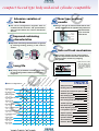
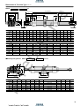
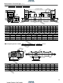
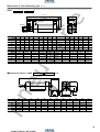
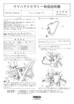
NEW DYNA CYLINDERS
ua
ir
e
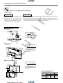
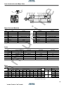
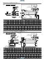
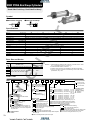
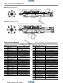
DYNA Cylinder
Highly reliable design of
with ISO standards.
The NEW DYNA cylinders, compact and lightweight mid-sized
actuators compatible with ISO standards, offers a wide range
of configurations and mounting types to meet various
application requirements with a flexible manner.
Moreover, the use of a new type cushion needle and
floating packing etc have made the product user-friendlier.
Caution
Before use, always read the Safety Precautions on p. 3.
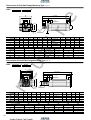
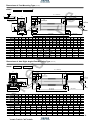
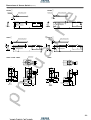
Variation
●Standard cylinders
●Tandem cylinders
●Double rod cylinders
●Non-rotating double rod cylinders
●Dual stroke cylinders
●Push side stroke adjusting cylinders
●Pull side stroke adjusting cylinders
●Valpack cylinders
●End keep cylinders
●Cylinders with brake
pn
e
●Low hydraulic cylinders
●Non-rotating cylinders
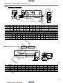
Mounting type
●Basic type
●Foot mounting type
●Axis right angled foot mounting type
●Rod side flange mounting type
●Head side flange mounting type
●Clevis mounting type with supporting bracket
●Pivot mounting type
●Trunnion type with supporting bracket
●ナックル
●Knuckles
●ジャバラ付
シリン
ダ
●Cylinder
with
bellows
Accessor y
●センサスイ
ッチ
●Sensor
switches
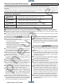
1
ua
ir
e
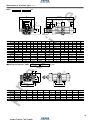
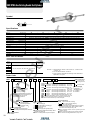
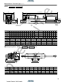
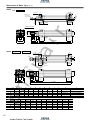
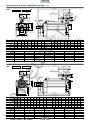
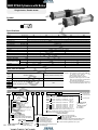
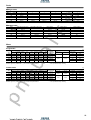
compact tie-rod type body mid-sized cylinder compatible
New type cushion
needle
Extensive variation of
functions
■ The series configuration together with its
combined wider functions and specifications
offer the best match for various mechanical
devices.
■ Using a new type of cushion needle that is completely embedded in the cylinder body offers fine
adjustment leading to increased
Snap ring
performance.
O ring
Improved cushioning
characteristics
Cushion needle
■ Improved cushioning characteristics are gained
by utilising floating packing in the cushion
section.
Safe self-lock mechanism
■ New release of brake cylinder range. Exhaustion of compressed air activates a brake shoes
onto the piston rod there by stopping
the cylinder.
Air flow
Spring
※Steel balls and a brake
shoe are fixed in position. By operating the
brake piston enables
activation or release of
the brake.
Brake piston
Long life
(φ40∼φ100)
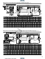
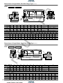
Double rod cylinder
(φ32∼φ125)
Non-rotating double rod cylinder
(φ40∼φ100)
Tandem cylinder
(φ40∼φ100)
Dual stroke cylinder
(φ40∼φ100)
Push side stroke adjusting cylinder
(φ40∼φ100)
Pull side stroke adjusting cylinder
(φ40∼φ100)
Low hydraulic cylinder
(φ32∼φ100)
Valpack cylinder
(φ40∼φ100)
End keep cylinder
(φ40∼φ100)
Brake cylinder
ef
typ
lan
e
ge
Clev
mo
is m
un
oun
t
ing
ting
type
typ
(with
e
Piv
supp
ot
o
r
t
ing b
mo
rack
un
ets)
tin
Tru
g
nnio
typ
n ty
e
pe (
with
sup
por
ting
bra
cke
ts)
mo
ge
foo
t
INDEX
sid
ad
He
Ro
ds
ide
flan
led
ang
nti
s ri
ght
Axi
Steel ball
un
unt
mo
e
typ
Non-rotating cylinder
tm
ou
typ
e
ng
Standard cylinder
(φ32∼φ125)
Fo
o
Ba
sic
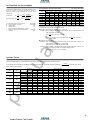
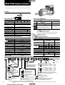
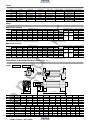
■Series configurations
Brake shoe
ting
ing
typ
e
pn
e
■ By using oil-permeated sintered copper alloy
for the bushing enables stable operation and
longer life.
Safety Precautions
3
Handling Instructions and Precautions
7
Air Flow Rate, Air Consumption and Cylinder Thrust
10
Standard Cylinders
11
Non-rotating Cylinders
19
Double Rod Cylinders
27
Non-rotating Double Rod Cylinders
33
Tandem Cylinders
39
Dual Stroke Cylinders
47
Stroke Adjusting Cylinders
53
Low Hydraulic Cylinders
63
Valpack Cylinders
71
End Keep Cylinder
79
Cylinders with Brake
83
Sensor Switches
97
Knuckles, Bellows
105
(φ40∼φ100)
2
Safety Precautions (New DYNA Cylinders)
Always read these precautions carefully before use.
ua
ir
e
Before selecting and using products, please read all the Safety Precautions carefully to ensure proper product use.
The Safety Precautions shown below are to help you use the product safely and correctly, and to prevent injury or damage to assets
beforehand.
Follow the Safety Precautions for: ISO4414 (Pneumatic fluid power—Recommendations for the application of equipment to
transmission and control systems), JIS B 8370 (Pneumatic system regulations)
”“WARNING!”
”
The directions are ranked according to degree of potential danger or damage: “DANGER!”
“CAUTION!”
”and “ATTENTION!”
”
DANGER
WARNING
CAUTION
ATTENTION
Expresses situations that can be clearly predicted as dangerous.
If the noted danger is not avoided, it could result in death or serious injury.
It could also result in damage or destruction of assets.
Expresses situations that, while not immediately dangerous, could become dangerous.
If the noted danger is not avoided, it could result in death or serious injury.
It could also result in damage or destruction of assets.
Expresses situations that, while not immediately dangerous, could become dangerous.
If the noted danger is not avoided, it could result in light or semi-serious injury.
It could also result in damage or destruction of assets.
While there is little chance of injury, this content refers to points that should be observed for
appropriate use of the product.
■This product was designed and manufactured as parts for use in General Industrial Machinery.
■ Before selecting the equipment and using any product, always read the Safety Precautions, the Catalog, the Instruction Manual, etc.
■ After reading the Instruction Manual, etc., always place the Manual where it can be easily available for reference to users of this product.
■ If transferring or lending the product to an another person, always attach the Instruction Manual, etc., to the product where it is easily
visible, to ensure that the new user can use the product safely and properly.
■ The danger, warning, and caution items listed under these “Safety Precautions” do not cover all possible cases. Read the catalog
and user’s manual carefully, and always keep safety first.
DANGER
pn
e
● Do not use for the purposes listed below:
1. Medical equipment related to maintenance or management
of human lives or bodies.
2. Mechanical devices or equipment designed for the purpose
of moving or transporting people.
3. Critical safety components in mechanical devices.
This product has not been planned or designed for
purposes that require advanced stages of safety. It could
cause injury to human life.
● Do not use in locations with or near dangerous substances
such as flammable or ignitable substances. This product is not
explosion prevention type. It could ignite or burst into flames.
● When attaching the product, always ensure that it is securely
fixed in place. Dropping or falling the product or improper
operation could result in injury.
● Persons who use a pacemaker, etc., should keep a distance
of at least one meter away from the product. There is the
possibility that the pacemaker will malfunction due to the
strong magnet built into the product.
● Never attempt to rebuild the product. It could result in
abnormal operation leading to injury, electric shock, fire, etc.
● Never attempt inappropriate disassembly or assembly of the
product’s basic configurations, or of its performance or
functions. It could result in injury, electric shock, fire, etc.
● Do not splash water on the product. Spraying it with water,
washing it, or using it underwater could result in malfunction
of the product leading to injury, electric shock, fire, etc.
● While the product is in operation, avoid touching it with your
hands or otherwise approaching too close. In addition, do not
make any adjustments to the interior or to the attached
mechanisms (removal, etc., of shock absorber, stroke
adjustment mechanism, sensor switch mounting position,
piping tubes, or sealing plugs) while in operation. The
actuator can move suddenly, possibly resulting in injury.
● When operating the product, always install a speed controller,
and gradually loosen the needle valve from a choked state to
adjust the speed increasing. Failure to make this adjustment
could result in sudden blasts of air, putting lives at risk.
3
●Do not apply loads to the piston rod that exceed its buckling or
bending strength. It could reduce the product’s working life, or
cause abnormal wear or damage to the rod or tube.
●Always install the piston rod axial center and load so that their
movement directions are aligned. A misalignment applies
excessive force on the piston rod and tube that could lead to
abnormal wear or to breakage.
WARNING
● Do not use this product in excess of its specification range.
Such use could result in product breakdowns, function stop or
damage.
● Before supplying air or electricity to the device and before
starting operation, always conduct a safety check of the area
of machine operation. Careless supply of air or electricity
could possibly result in electric shocks, or in injury caused by
contact with moving parts.
● Do not touch the terminal and the miscellaneous switches,
etc., while the device is plugged in. There is the possibility of
electric shock and abnormal operation.
● Do not allow the product to be thrown into fire. The product
could explode and release toxic gases.
● Do not sit on the product, place your foot on it, or place other
objects on it. Accidents such as falling and tripping over could
result in injury. Dropping the product may damage or break the
product resulting in abnormal, improper or erratic operation.
● When conducting any kind of operation for the product, such
as inspection, repair, installation/removal of piping, or
replacement, always turn off the air supply completely and
confirm that residual pressure inside the product or in piping
connected to the product is zero before proceeding. In
particular, be aware that residual air will still be in the air
compressor or air storage tank. The actuator could abruptly move
if residual air pressure remains inside the piping, causing injury.
● Do not use the actuator for equipment whose purpose is
absorbing the shocks and vibrations of mechanical devices. It
could break and possibly result in injury or in damage to
mechanical devices.
ATTENTION
● When considering the possibility of using this product in
situations or environments not specifically noted in the
Catalog or user’s Manual, or in applications where safety is
an important requirement, such as in an airplane facility,
combustion equipment, leisure equipment, safety equipment
and other places where human life or assets may be greatly
affected, take adequate safety precautions such as
application with enough margins or fail-safe measures for
ratings and performance. Please consult KOGANEI with any
questions.
● Always check the catalog and other reference materials for
product wiring and piping.
● Use a protective cover, etc., to ensure that human bodies do
not come into direct contact with the operating space of
mechanical devices, etc.
● Do not control in a way that would cause work to fall during
power failure. Set the controls so that they prevent the table
or work, etc., from falling during power failure or emergency
stop of the mechanical devices.
● When handling the product, wear protective gloves, safety
glasses, safety boots, etc., to assure safety.
● When the product can no longer be used, or is no longer
necessary, dispose of it appropriately as industrial waste.
● Pneumatic equipment can exhibit degraded performance and
function over its operating life. Always conduct daily
inspections of the pneumatic equipment, and confirm that all
requisite system functions are satisfied, to prevent accidents
from happening.
● For inquiries about the product, contact your nearest Koganei
sales office or Koganei overseas division. The address and
telephone number is shown on the back cover of this catalog.
ua
ir
e
● Avoid scratching the cords for the sensor switch lead wires, etc.
Letting the cords be subject to scratching, excessive
bending, pulling, rolling up, or being placed under heavy
objects or squeezed between two objects, may result in
current leaks or defective transmission that lead to fires,
electric shocks, or abnormal operation.
● Do not apply a lateral load of more than 1/20th of the cylinder
thrust onto the cylinder rod bushing section. It could result in a
shortened operating life, and in scratches or breakage of the
rod or cylinder tube.
● Always use within the recommended load and specified
speed. Use at levels exceeding the recommended loads or
specified speeds could cause the piston rod or attaching plate
to move suddenly, damaging the unit and causing injuries.
●Use safety circuits or system designs to prevent damage to
machinery or injury to personnel when the machine shuts
down due to an emergency stop or electrical power failure.
●Install relief valves, etc., to ensure that the actuator does not
exceed its rated pressure when such pressure is increasing
due to external forces on the actuator. Excessive pressure
could lead to breakdown and damage.
CAUTION
pn
e
● Do not use in locations under direct sunlight (ultraviolet), in
locations subject to dust, salt, or iron powder, or in the media
and/or the ambient atmospheres that include organic
solvents, phosphoric ester-based hydraulic fluids, sulfur
dioxide gas, chlorine gas and acids. These conditions could
lead to functional shutdowns, sudden degraded performance,
or shortened operating life in a brief period of time. For the
materials used, see Major Parts and Materials.
● When mounting the product, leave room for adequate
working space around it. Failure to assure adequate working
space will make it more difficult to conduct daily inspections
or maintenance, which could eventually lead to system
shutdown or damage to the product.
●When transporting or installing heavy products, use a lift or
support to firmly hold it up, or use a large number of people,
and take full precautions to ensure personal safety.
● Do not bring floppy disks and magnetic media, etc., within
one meter of the product. There is the possibility that the
data on the floppy disks will be destroyed due to the
magnetism of the magnet.
● Do not use the sensor switch in locations subject to large
electrical currents or powerful magnetic fields. It could result
in erratic operation. In addition, do not use magnetized
materials in the mounting bracket. The magnetic force could
be reduced, possibly resulting in erratic operation.
● Never use another company’s sensor switch with these
products. It could possibly cause error or accidental operation.
● Do not scratch, dent, or deform the actuator by climbing on
the product, using it as scaffold, or placing objects on the top
of it. It could result in damaged or broken products that result
in operation shutdown or degraded performance.
● When performing mounting or adjustment work, put up “now
working” signs to prevent applying unintentional air or
electrical power, etc. Such applying accidental inputs may
cause electrical shock, or sudden activation of the actuator
that could result in physical injury.
OTHER
● Always observe the following items.
KOGANEI cannot be responsible if these items are not
properly observed.
1. When using this product in pneumatic systems, always
use genuine KOGANEI parts or compatible parts
(recommended parts).
When conducting maintenance and repairs, always use
genuine KOGANEI parts or compatible parts (recommended parts). Always observe the required methods.
2. Do not attempt inappropriate disassembly or assembly of
the product relating to basic configurations, or its
performance or functions.
4
Safety Precautions (Sensor Switch)
Design and Selection
ua
ir
e
Warning
Installation and Adjustment
Warning
1.Check the specifications.
As use of this equipment over the specified ranges of voltage,
current, temperature, shock, etc., could result in breakdown
or abnormal operation, always read the specifications
carefully to ensure correct use.
2.Avoid mounting cylinders in close proximity.
Mounting two or more cylinders with sensor switches in close
proximity could result in erroneous operation of the sensor
switch, due to magnetic field interference with the system.
3.Be cautious about sensor switch ON times for
positioning detection at intermediate stroke position.
Be aware that if the sensor switch is mounted at an
intermediate position of the cylinder stroke for detection of the
piston travel, the sensor switch actuation time may be too
short when the cylinder speed is very rapid, so that the load
(sequencer, etc.) may fail to activate.
Maximum cylinder speed for positioning detection
V
〔mm/s〕
=
Sensor switch actuation range〔mm〕
Time required for activating load〔ms〕
×1000
4.Keep wiring as short as possible
In reed sensor switches, in particular, excessively long wiring
(10m or more) can shorten the operating life of the sensor
switch with capacitive surges. If the wiring must be lengthy,
install the protection circuits for inductive or capacitive loads,
as well.
5.Avoid repeated or excessive bending or pulling of
lead wires.
Applying repeated bending stress or tension force on the lead
wire could result in wire breaks.
6.Check for leak current.
4.Two-lead wire solid state sensor switches produce leak current to
pn
e
activate their internal circuits, and the current flows even when
turned off. Check to ensure they satisfy the following formula.
Input-off current of programmable controller > Leak current
If the above formula cannot be satisfied, select a three-lead wire
solid state sensor switch, instead. Also note that parallel
connection of a total of n sensor switches will lead to n times the
leak current.
Caution
1.Check for sensor switch internal voltage drop.
Series connection of reed sensor switches with indicator
lamps or two-lead wire solid state sensor switches causes
increasing internal voltage drop, and the load may fail to
activate. A total of n sensor switches will lead to n times the
internal voltage drop. Ensure that the system satisfies the
following formula.
Supply voltage – Internal voltage drop × n > Minimum
operating voltage for load
In relays with rated voltage of less than 24VDC, check to see
whether the above formula is satisfied, even in the case of n = 1.
If the above formula cannot be satisfied, select either a reed
sensor switch without indicator lamp, or a three-lead wire
solid state sensor switch.
2.Do not use with other companies’ cylinders.
5
The sensor switches are designed for use with Koganei
cylinders. Use with other companies’ cylinders could lead to
abnormal operation.
3. Never use another company’s sensor switch on these
products.
It could result in erroneous or runaway operation.
1.Do not apply an external magnetic force to the
sensor switch while the cylinder is in operation.
It could result in unintentional operation that could damage
the unit or cause personal injury.
Caution
1.Ensure a safe environment for the sensor cylinder
mounting.
Do not use sensor switches in places where a large current or
magnetic fields are present. This could lead to unintentional
operation. Do not use magnetic material for the mounting
brackets. Magnetic force could leak out, resulting in
erroneous operation.
2.Install sensor switches in the center of its operating
range.
Adjust the mounting position of a sensor switch so that the
piston stops in the center of its operating range (the range
where the sensor turns on). Operations can be unstable if
mounted at the end of the operating range (at the boundary
near ON and OFF). Also be aware that the operating range
can vary with changes in temperature.
3.Maintain the tightening torque of sensor switches
when mounting.
Over-tightening beyond the allowed fastening torque may
damage the mounting screws, mounting brackets, sensor
switches, etc. In addition, insufficient tightening torque could
cause the sensor switch position to change, resulting in
operating instability.
For the tightening torque, see the Instruction for Detaching
and Moving of Sensor Switch on p.103.
4.Do not use sensor switch lead wires to lift a cylinder.
After mounting a sensor switch to a cylinder, do not grab the lead
wires to lift the cylinder. Never do this, as it could result in lead
wire disconnections, and could also apply stress to the interior of
the sensor switch, resulting in breakage of internal elements.
5.Do not drop switches, or bump them against others.
During handling of switches, do not apply excessive shocks
(294.2m/s2 {30G} or more) such as hitting, dropping, or bumping.
In reed sensor switches, the contact reed can be activated
unintentionally, causing it to send or break sudden signals. It
can also cause changes in the contact interval that lead to
changes in sensor switch sensitivity and result in erratic
operation. Even if the sensor switch case is undamaged, the
inner parts of the sensor switch may suffer breakdowns or
cause erratic operation.
Wiring
Danger
1.Avoid letting moving objects near a sensor switch
come into contact with it.
When cylinders with sensor switches move, or when moving
objects are nearby, do not let the moving objects come into
contact. In particular, lead wires could become worn out or
damaged, inducing operating instability in the sensor switch. In
the worst case, it could result in current leaks or electrical shocks.
2. Always turn off the power supply for wiring work.
Conducting wiring work while the power is on could result in
electric shocks. Also, wiring errors could damage sensor
switches in an instant. Turn on the power only after wiring
work is complete.
Warning
Handling Instructions, and Precautions
General Precautions
ua
ir
e
Safety Precautions (Sensor Switch)
1.Always check the Catalog, etc., to correctly conduct
sensor switch wiring.
Mis-wiring could result in abnormal operations.
2.Do not share the same wiring with power or high
voltage lines.
Avoid wiring in parallel to or shared with power or high voltage
lines. The sensor switch or control circuit may suffer electric noise
that results in erratic operation.
3.Avoid repeated or excessive bending or pulling of
lead wires.
Media
1. Use air for media. Consult us for the use of any other media.
2. Air used for the cylinder should be clean air that contains no
deteriorated compressor oil, etc. Install an air filter (filtration of
40 µm or less) near the cylinder or valve to remove drain
contaminants or dust. In addition, drain the air filter
periodically.
Piping
Always thoroughly flush out (blow with compressed air) the
piping before connecting it to the cylinder. Entering metal chips,
sealing tape, rust, etc., generated during plumbing could cause
air leaks or other malfunctions.
Atmosphere
Install a cover, etc., or appropriate protective devices when
operating in locations near excessive water, oil, etc., or large
amounts of dust.
Lubrication
This equipment can be used without lubrication. If lubrication is
used, it must be turbine oil Class 1(ISO VG32) or its equivalent.
Avoid using spindle oil or machine oil.
Applying repeated bending stress or tension force on the lead
wire could result in wire breaks.
4.Check polarity in the wiring
In sensor switches that specify polarity (+, –, output), be sure
that wiring connections are correct. The wrong polarity could
result in damage to the sensor switch.
pn
e
Caution
1. Avoid short circuiting the loads.
Turning a sensor switch on while the load is short-circuited
causes overcurrent, which can damage the sensor switch in
an instant. Example of short-circuited load: Sensor switch’s
output lead wire is directly connected to the power supply.
6
Handling Instructions and Precautions
Manual override of end keep
cylinder locking mechanism
Assembly of mounting bracket
Use mounting screws which are supplied with the
bracket to assemble the mounting bracket. Use a
hexagonal bar wrench to tighten the mounting
screws evenly. When four screws are used, tighten
diagonally from each corner. The tightening torque
is shown below.
Assembly and disassembly
For disassembly, insert a hexagonal bar wrench to
loosen the tie rod nut, and remove the cover.
For assembly, screw in the tie rod nut with the
hexagonal socket facing outward. Evenly tighten
diagonally from each corner. The tightening torques
are the values shown below.
While the locking mechanism is normally released
automatically through cylinder operations, it can
also be released manually. For manual release,
insert an M4×0.7 screw that is 30mm long from the
neck into the manual override opening, thread it in
about three turns into the internal lock piston, and
then pull up the screw. To maintain a state of
temporary release for adjustment, etc., pair the
screw with a lock nut and, with the lock in a
released state, tighten the lock nut against the
cylinder side.
Cautions: 1. It is dangerous to supply air to a
connection port on a side with a
locking mechanism while the cylinder
has already exhausted, because the
piston rod may suddenly extend (or
retract). In addition, since the lock
piston could scuff the piston rod,
perhaps resulting in abnormal
operation, always supply air to the
connection port on the opposite side
to ensure applying back pressure.
2. When restarting operations after air
has been exhausted from the
cylinder due to completion of
operations or to an emergency stop,
always start by supplying air to a
connection port on the side without a
locking mechanism.
3. Connect valve port A (NC) to a
connection port on the side with a
locking mechanism.
Tightening torque
32・40・50
4.81N・m
63
12.0N・m
80・100
24.0N・m
125
42.2N・m
●Width across flats of hexagonal socket mm
Bore size
Tie rod nut
Mounting bracket
32
6
4
40・50
6
63
8
80・100
10
125
12
●φ32
4
5
6
8
pn
e
Head cover
Use hexagon socket
tie rod nut on both
sides for only 32φ
∼φ125
●φ40∼
Hexagon socket tie rod nut
Head cover
Hexagon socket tie rod nut
Tie rod nut with knurling
7
1. For control of the DYNA end keep cylinder,
we recommend the use of 2-position, 4-,5port valves. Avoid the use of 3-position
valves in ABR connections (exhaust centers)
or other control circuits that exhaust air from
both ports.
2. Always use meter-out control for speed
control. Meter-in control may result in failure
of the locking mechanism to release.
3. Always set the air pressure to 0.15MPa
{1.5kgf/cm2} or more.
Small screw M4×0.7
(length appr. 30mm)
〈Tightening torques of mounting brackets and
tie rod nuts〉
Bore size
Control circuits for the
end keep cylinder
ua
ir
e
Handling
Cautions: 1. It is dangerous to release the lock
when load (weight) is present on the
piston rod because it may result in a
sudden drop or cause the piston rod
to extend (or retract). In this case,
always supply air to a connection
port on the side without the locking
mechanism before releasing the
locking mechanism.
2. If the locking mechanism cannot
easily be released even with
manual override, it could be the
result of the lock piston and piston
rod scuffing. In this case, supply air
to a connection port on the side
without the locking mechanism
before releasing the locking
mechanism.
3. Because water, oil, dust, etc.,
intruding through the manual override opening may be a cause of
defective locks or other erratic
operations, use a cover, etc., for
protection when using in locations
subject to dripping water, dripping
oil, or to a large amount of dust, etc.
4. If the circuit cannot maintain
exhaust pressure at 0.03MPa
{0.3kgf/cm2} or less due to using a
manifold valve, use individual valve
for operations.
ua
ir
e
Handling Instructions and Precautions
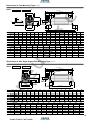
Installation and piping (cylinder with brake)
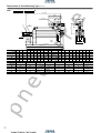
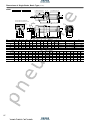
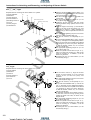
Operating principle
The cylinder with brake uses a mechanism that consists of steel balls contacting a slope and it
receives components of a spring force, then it transmits the force via a brake shoe to apply to the
piston rod.
When the brake is released
●When the brake is released
Brake piston
Spring
Brake releasing port
Taper ring
●When the brake is activated
Brake shoe
A supply of compressed air from the brake
releasing port causes the brake piston
including the taper ring to retract and frees
the steel balls contact from the taper ring,
which releases the brake and lets the piston
rod freely slide.
When the brake is activated
Steel ball
Exhausting compressed air from the brake
releasing port causes the spring to press
against the brake piston, transmitting
component of a spring force via the taper ring
to the steel balls, which then works via the
brake shoe to transmit a perpendicular force
to the piston rod and to apply friction force to
the brake.
Precautions during installation
pn
e
1. In the cylinder with brake, the brake piston in the single brake type is fixed in place with two
hexagon socket set screws, and in the double brake type with four such screws, with the
brake set in a released state at time of delivery.
When piping and installation is completed, or when performing operation checks, firstly supply
air at least 0.35MPa (0.4MPa for an inner diameter of φ50) from the brake release port, and
remove the set screws. Then, by exhausting off the compressed air enables to hold the piston
rod. While the unit could be operated with the set screws removed, it is better for prevention
of entering dust to use two set screws with nuts to fix it in place by inserting 2 or 3 ridges into
the cylinder.
At this time, do not tighten the set screws too excessive as it could interfere with brake piston,
by re-locking it in place, or by constricting its movements.
2. Poor centering of the cylinder with brake may damage the seal or hasten wear on the brake
shoe.
As poor centering could also result in variation of the stopping position, use of a cylinder joint
is recommended.
Brake lock release screw
Single brake : 2 locations
Double brake: 4 locations
During use, loosen the brake lock release
screw, and set so that it does not bump
against the brake piston.
Brake piston
Brake lock release screw
(Hexagonal socket set screw)
8
ua
ir
e
Handling Instructions and Precautions
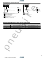
Installation and piping (cylinder with brake)
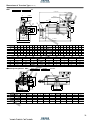
Control circuit
Electric control
Pneumatic circuit
If using a sequencer for control, the
sequencer scan time will result in stop
position errors. To improve the stopping
positioning accuracy, use signals from the
cylinder's sensor switch and use direct control
via a TTL circuit, etc., for switching valves.
1. To ensure balance with the load, and balance with the difference in rod diameter sizes, always use
a regulator with check valve.
2. Use a PAB connection 3-position solenoid valve, etc., as the cylinder operating solenoid valve (V1).
3. Mount a solenoid valve for brake (V2) as closely as possible to the cylinder, while use of a DC
current solenoid valve will improve response (stopping position accuracy).
Example of standard circuit (Reference)
●Horizontal mounting
●Spring lock
W
SP2
Regulator pressure setting
D2−d2
P2=
・P1
D2
SP1
(P2)
D : Cylinder bore size (mm)
d : Rod diameter (mm)
P1 : Supply pressure (MPa)
REG
SOL3
SOL1
V2
SOL2
V1
(P1)
●Vertical mounting
●Spring lock
SP1
Regulator pressure setting
π(D2−d2) P1−4W
P2=
π・D2
(P2)
REG
D : Cylinder bore size (mm)
d : Rod diameter (mm)
P1 : Supply pressure (MPa)
W : Load(N)
pn
e
SOL1
SP2
SOL2
(P1)
W
SOL3
●Vertical mounting(thrust up)
Regulator pressure setting
π・D2・P1−4W
P2=
π(D2−d2)
SOL3
V2
SOL1
W
(P2)
SP2
V1
REG
(P1)
ON, OFF switch sequence for solenoid
(same for all mounting positions)
Valve
SOL2
V2
V1
SOL1
SOL2
SOL3
Intermediate stop
OFF
OFF
OFF
Forward
OFF
ON
ON
Reverse
ON
OFF
ON
Operating state
SP1
9
D : Cylinder bore size (mm)
d : Rod diameter (mm)
P1 : Supply pressure (MPa)
W : Load(N)
Air Flow Rate, Air Consumption
Air flow rate
Air consumption for every 1mm stroke
Bore size
mm
P+0.1013
60
πD2
-6
Q1= 4 ×L× ×
0.1013 ×10
t
P+0.1013
πD2
Air consumption Q2= 4 ×L×2×n 0.1013 ×10⁻⁶
Q1
Q2
D
L
t
n
p
cm3/Reciprocation (ANR)
Air pressure MPa
0.1
0.2
0.3
0.4
0.5
0.6
0.7
0.8
0.9
32
3.20
4.78
6.37
7.96
9.55
11.14
12.72
14.31
15.90
40
4.99
7.48
9.96
12.44
14.92
17.40
19.88
22.36
24.84
50
7.80
11.68
15.56
19.43
23.31
27.19
31.06
34.93
38.78
63
12.39
18.54
24.70
30.85
37.01
43.16
49.32
55.46
61.57
80
19.98
29.90
39.83
49.75
59.67
69.60
79.52
89.45
99.37
100
31.21
46.72
62.23
77.73
93.24 108.75 124.25 139.76 155.27
125
48.77
73.00
97.23
ua
ir
e
While the air cylinder's air flow rate and air consumption can
be found through the following calculation, the quick
reference chart at right provides the answers more
conveniently.
: Necessary air flow rate for cylinder
R/min(ANR)
: Air consumption of cylinder
R/min(ANR)
: Cylinder bore
mm
mm
: Cylinder stroke
s
: Time necessary that cylinder travels one stroke
: Number of cylinder reciprocations per minute
times/min
: Pressure
MPa
121.46 145.69 169.92 194.14 218.37 242.60
The figures in the table are for calculating the air flow rate and air consumption during one
reciprocation of an air cylinder with stroke of 1mm. The actual air flow and consumption
required can be found through the following method.
●Finding the air flow rate (for selecting F.R.L., valves, etc.)
Example When operating an air cylinder with bore size of 40mm at speed of 300mm/s and
under air pressure of 0.5MPa
1
14.92× ×300×10-3≒2.21R/s (ANR)
2
1
(At this time, the air flow per minute becomes 14.92× ×300×60×10-3=
2
134.28R/min (ANR))
●Finding the air consumption
Example 1. When operating an air cylinder with bore size of 40mm and stroke of 100mm, and
under air pressure of 0.5MPa, for 1 reciprocation
14.92×100×10-3=1.492R/Reciprocation (ANR)
Example 2. When operating an air cylinder with bore size of 40mm and stroke of 100mm, and
under air pressure of 0.5MPa, for 10 reciprocations per minute
14.92×100×10×10-3=14.92R/min (ANR)
Cylinder Thrust
Find the required thrust for a given load and air pressure, and select the appropriate cylinder bore size.
Load
Since the figures in the table are calculated values, select the bore size so that the load ratio (load ratio =
) becomes 70% or less
Calculation value
(50% or less for high speeds).
N
Rod diameter
mm
Operation
Pressure
area mm2
Air pressure MPa
0.3
0.4
0.5
0.6
0.7
0.8
0.9
1
Push side
804
0.1
80
0.2
61
241
322
402
482
563
643
724
804
Pull side
690
69
138
207
276
345
414
483
552
621
690
Push side
1256
126
251
377
502
628
754
879
1005
1130
1256
pn
e
Bore size
mm
32
40
50
63
80
100
125
12
16
20
20
25
30
35
Pull side
1055
106
211
317
422
528
633
739
844
950
1055
Push side
1963
196
393
589
785
982
1178
1374
1570
1767
1963
Pull side
1649
165
330
495
660
825
989
1154
1319
1484
1649
Push side
3117
312
623
935
1247
1559
1870
2182
2494
2805
3117
Pull side
2803
280
561
841
1121
1402
1682
1962
2242
2523
2803
Push side
5026
503
1005
1508
2010
2513
3016
3518
4021
4523
5026
Pull side
4536
454
907
1361
1814
2268
2722
3175
3629
4082
4536
Push side
7853
785
1571
2356
3141
3927
4712
5497
6282
7068
7853
Pull side
7147
715
1429
2144
2859
3574
4288
5003
5718
6432
7147
Push side
12271
1227
2454
3681
4908
6136
7363
8590
9817
11044
12271
Pull side
11310
1131
2262
3393
4524
5655
6786
7917
9048
10179
11310
10
Symbol
Specifications
ua
ir
e
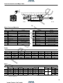
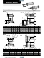
NEW DYNA Standard Cylinders
Bore size mm
Item
40
32
50
63
80
100
125
Double acting type
Operating method
Air
Media
Mounting type
Basic type, Foot mounting type, Axis right angled foot mounting type, Rod side flange mounting type, Head side flange mounting type, Clevis mounting type, Pivot mounting type, Trunnion type
Operating pressure range
MPa{kgf/cm2}
Proof pressure
MPa{kgf/cm2}
Operating temperature range
Operating speed range
0.05∼1.0 {0.5∼10.2}
1.5 {15.3}
°C
mm/s
―10∼70 (Freezing not allowed, with sensor is 0∼60, Heat resistant type is 5∼120 Note )
30∼800
30∼700
Variable cushion at both ends of stroke
Cushion
Cushion stroke
mm
16
25
20
Not required (But if you must use lubrication, use Turbine Oil No.1
〔ISO VG32〕or equivalent)
Lubrication
Port size
Rc
1/8
1/4
3/8
1/2
Bore size and Stroke
mm
Bore
Maximum potential manufacturing stroke
Standard specification Non-ion specification
Standard stroke
sizer
(Aluminum tube)
Heat resistant type
Steel tube specification
Remarks: 1. Stroke tolerance: Strokes of 250 or less are
+1 , strokes of 251∼1000 are +1.5 , and
+0
+0
strokes of 1001 or more are +2.0
+0 .
32
50, 75, 100, 150, 200, 250, 300, 350, 400, 450, 500, 600, 700
700
700
40
50, 75, 100, 150, 200, 250, 300, 350, 400, 450, 500, 600, 700
1000
1000
50
800
1500
1500
2. For non-standard strokes, consult us.
3. Cylinders with magnets are not available in
heat resistant and steel tube specifications.
1500
1500
4. For the maximum potential manufacturing
stroke with bellows specification, see p.104.
63
80
800, 900, 1000
pn
e
100
50, 75, 100, 150, 200, 250, 300, 350, 400, 450, 500, 600, 700
125
Order Code
DDA
50×100
−
Bore size
×
Stroke
Non-ion specification
Blank Standard
NCU
Non-ion specification
−
−
−
Tube material
Blank Standard
(Aluminum tube)
FT
Steel tube specification
Not available for cylinder
with magnet.
(
)
Types of bellows
JT
Nylon tarpaulin (∼80˚C)
JC
Chloroprene (∼100˚C)
JK
Cornex (∼200˚C)
JA
Arumix (∼250˚C)
●Cornex is a registered trademark of Teijin, Inc.
●The temperature shown is the bellows own durable
temperature, and is not a temperature for cylinder use.
Cylinder specification
Blank Standard cylinders
F
Heat resistant cylinders (Not available for cylinder with magnet.) Note
J
Standard cylinder with bellows
FJ
Heat-resistant cylinder with bellows
(Not available for cylinder with magnet.)
NEW DYNA Cylinders
Basic model
●Combinations of heat resistant, non-ion, and steel tube
specifications are made to order.
11
−
Note: Heat resistant type not available inφ32 and φ125.
−
Number of sensor switches
1
With one sensor switch
2
With two sensor switches
⋮
⋮
n
With n sensor switches
Sensor switch (for cylinder with magnet)
ZC130
2-lead wires Solid state type with indicator lamp DC10∼28V
ZC153
3-lead wires Solid state type with indicator lamp DC4.5∼28V
CS5T
2-lead wires Reed switch type without indicator lamp DC5∼28V
Lead wire length
AC85∼115V
Applicable to
CS11T 2-lead wires Reed switch type with indicator lamp DC10∼28V
ZC,CS□T type
CS2F
DIN type Reed switch type with indicator lamp AC85∼230V A : 1000mm
CS3F
DIN type Reed switch type with indicator lamp DC10∼30V
B : 3000mm
CS4F
DIN type Reed switch type with indicator lamp DC10∼30V
CS5F
DIN type Reed switch type without indicator lamp DC3∼30V
●For sensor switch specifications, see p.97, while for mountings, see p.101.
●CS□F comes with a DIN connector. All others are grommet type.
●Orders for sensor switches only also accepted.
(
)
Rod end mounting
Mounting type
Blank Without rod end mounting
Blank Basic type
Y
With Y type knuckle (with pin)
1
Foot mounting type
I
With I type knuckle
2
Axis right angled foot mounting type
●Place separate orders for the cylinder joint and cylinder rod end.
3
Rod side flange mounting type
●Orders for rod end mountings only are also accepted.
5
Head side flange mounting type
●For rod end mountings dimensions, see p.105.
7
Clevis mounting type (with pin)
7-7C
Clevis mounting type (with supporting brackets)
8
Pivot mounting type
11
Trunnion type
11-11T Trunnion type (with supporting bracket)
●Mounting brackets are included at time of delivery, with the exception of the trunnion type.
●Orders for mounting brackets only are also accepted.
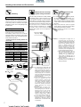
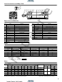
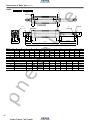
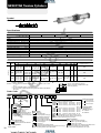
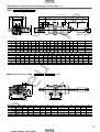
Inner Construction and Major Parts
!2
!9
!1
e w q i !7 !0 o @0 !8 t !4
ua
ir
e
!5 !6 y !3 r u @0 !8
Major Parts and Materials
No.
Parts
q
q
Cylinder tube
w
w
Piston rod
e
e
Tie rod
r
r
Rod cover
t
t
Head cover
y
y
Rod bushing
u
u
Keep ring
i
i
Piston
o
o
Wear ring
!0
!0
Magnet
!1
!1
Cushion needle
!2
!2
Snap ring
!3
!3
Tie rod nut R
!4
!4
Tie rod nut H
!5
!5
Rod end nut
!6
!6
Rod seal
No.
!7
!7
Piston seal
φ32:Stainless steel, φ40∼φ125:Carbon steel for machine structural use
!8
!8
Cushion seal
Synthetic rubber(NBR)
Carbon steel for machine structural use
!9
!9
Cushion gasket
Synthetic rubber(NBR)
Aluminum die-cast
@0
@0
Tube gasket
Synthetic rubber(NBR)
Aluminum die-cast
―
Foot bracket
Rolled steel for general structural use
Oil-permeated sintered copper alloy
―
Axial right angled foot bracket
Aluminum alloy
―
Flange mounting bracket
Rolled steel for general structural use
Aluminum alloy
―
Clevis mounting bracket
Cast iron
Plastic
―
Clevis supporting bracket
Cast iron
Rubber magnet
―
Pivot bracket
Cast iron
Carbon steel for machine structural use
―
Trunnion bracket
Cast iron
Spring steel
―
Trunnion supporting bracket
Rolled steel for general structural use
―
Knuckles
Parts
Materials
Synthetic rubber(NBR)
Cast iron
Cast iron
Cast ironNote
Note:The I knuckle for φ125 only, is carbon steel for machine structural use
Chrome-molybdenum steel
Rolled steel for general structural use
Synthetic rubber (NBR)
Seals
Parts
Quantity
Rod seal
Piston seal
Cushion seal
Tube gasket
1★
1★
2
2★
2
pn
e
Bore size mm
Materials
Aluminum alloy, and steel tube specification is high carbon steel
Cushion gasket
32
DRP12
PWP32N
CPF15
1.5×32
S5
40
DRP16 (DRP16F)
PWP40N (PSD-40F)
CPF20 (PCS20F)
1.5×40
S5
50
DRP20 (DRP20F)
PWP50N (PSD-50F)
CPF24 (PCS24F)
1.5×50
S6
63
DRP20 (DRP20F)
PWP63N (PSD-63F)
CPF24 (PCS24F)
1.5×63
S6
80
DRP25 (DRP25F)
PWP80N (PSD-80F)
CPF30 (PCS30F)
1.5×80
S6
100
DRP30 (DRP30F)
PWP100N (PSD-100F)
CPF35 (PCS35F)
1.5×100
S6
125
DRP35
PWP125N
CPF45
2.0×125
S7
Remarks: 1. Items in parentheses ( ) are for heat resistant specifications.
2. Starred ★ designate items available as repair kits.
Order code
For standard cylinders・・・SRK-NDDA Bore size
Mass
Bore size
mm
32
40
50
63
80
100
125
Basic
type
0.57
(0.60)
0.65
(0.69)
1.02
(1.08)
1.36
(1.44)
2.32
(2.49)
2.94
(3.15)
4.43
(4.77)
kg
Mass of one sensor switch [with holder] Mass of knuckle
Mass at zero stroke
Foot
Clevis mounting
Trunnion type Additional mass for ZC□□□
Clevis
Axial
perpendicular
Flange
Pivot
Trunnion
Y type knuckle I type
mounting
mounting type typ (with supporting
(with supporting each 1mm stroke
CS□F
foot mounting type mounting type (with pin)
type
knuckle
(with pin)
CS□T Note
type
bracket) mounting type
bracket)
0.00218
1.09
0.87
0.69
1.22
0.76
0.77
0.71
0.68
0.16
0.22
(0.00324)
(1.12)
(0.90)
(0.72)
(1.25)
(0.79)
(0.80)
(0.74)
(0.71)
0.78
(0.82)
1.19
(1.25)
1.59
(1.67)
2.70
(2.87)
3.41
(3.62)
4.90
(5.24)
0.85
(0.89)
1.34
(1.40)
1.88
(1.96)
3.17
(3.34)
4.22
(4.43)
5.81
(6.15)
1.02
(1.06)
1.41
(1.47)
1.89
(1.97)
3.92
(4.09)
5.16
(5.37)
7.30
(7.64)
0.92
(0.96)
1.41
(1.47)
1.84
(1.92)
3.24
(3.41)
4.18
(4.39)
6.40
(6.74)
1.62
(1.66)
2.11
(2.17)
2.54
(2.62)
3.96
(4.13)
4.90
(5.11)
9.21
(9.55)
Note: For lead wire length A (1000mm).
Remark: Figures in parentheses ( ) are for steel tube specifications.
0.83
(0.87)
1.28
(1.34)
1.78
(1.86)
3.40
(3.57)
4.33
(4.54)
6.88
(7.22)
1.13
(1.17)
1.57
(1.63)
2.06
(2.14)
3.48
(3.65)
4.47
(4.68)
7.84
(8.18)
1.63
(1.67)
2.07
(2.13)
2.56
(2.64)
4.20
(4.37)
5.19
(5.40)
9.39
(9.73)
0.00300
(0.00431)
0.00428
(0.00635)
0.00515
(0.00773)
0.00834
(0.01302)
0.01061
(0.01642)
0.01490
(0.02311)
0.04
0.04
0.046
0.05
0.06
0.066
0.27
0.16
0.34
0.21
0.34
0.21
0.87
0.62
1.47
1.24
1.47
1.24
Calculation example: For a foot mounting type with bore size of 50mm, and a
100mm stroke 1.19+(0.00428×100)=1.618kg
12
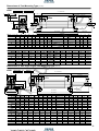
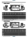
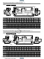
Dimensions of Basic Type (Unit mm)
Stroke
2‐Rc1/ 8
Connection port
16
16
ua
ir
e
DDA 32×
10(width across flats)
7
3
M10×1.25
25.5
25.5
2‐Cushion needle
(width across flats 2.5)
φ26
φ12
φ26
4×2‐M6×1 Depth 14
6
17
□33
□44
DDA
Bore size ×
2
19
32
15
31
31
93 +Stroke
142 +Stroke
47
2
Stroke
2‐O
Connection port
N
N
P
Q
W(width across flats)
Q
M
M
K
P
2-Y
(width across flats)
φD
φV
φD
pn
e
4×2‐L
J
I
□T
□S
E
G
B
G
C+Stroke
A+Stroke
R
A
B
C
D
E
F
G
H
I
J
K
40
144
49
93
32
34
15
31
21
22
8
M14×1.5
M 6×1
Depth 14
50
152
57
93
38
42
15
31
29
27
11
M18×1.5
M 6×1
Depth 14
63
155
57
96
38
42
15
32
29
27
11
M18×1.5
M 8×1.25 Depth 14
Bore size
L
80
185
75
108
44
54
21
36
37
32
13
M22×1.5
M10×1.5
Depth 15
100
185
75
108
50
54
21
36
37
36
14
M26×1.5
M10×1.5
Depth 15
125
205
89
114
60
68
21
36
50
36
16
M27×2
M12×1.75 Depth 15
Code
M
N
O
P
Q
R
S
T
V
W
Y
40
4
18
Rc1/4
25.5
10
2
50
37
16
14
2.5
50
7
18
Rc3/8
24
12
2
62
47
20
17
3
63
8
18
Rc3/8
25
12
2
75
56
20
17
3
80
11
20
Rc1/2
29
16
2
94
70
25
21
3
100
12
20
Rc1/2
29
18
2
112
84
30
26
3
125
14
20
Rc1/2
29
20
2
136
104
35
32
3
Bore size
13
Code
2
F
H
Dimensions of Foot Mounting Type (Unit mm)
DDA
Bore size ×
-1
Stroke
A+Stroke
□S
B
□T
C+Stroke
F
G
R
G
2-O
Connection port
ua
ir
e
E
I
H
2
N
N
AH
AT
AP2
AS
AP1
φV
J
K
View from Z
W
(width across flats)
AF
AD
AG
AG
AB
AE
AD
AC+Stroke
AA+Stroke
Z
Code
A
B
32
142
47
40
144
49
50
152
57
63
155
57
80
185
75
100
185
75
125
205
89
Bore size
Bore size
Code
AA
32
153
40
165
50
173
63
184
80
200
100
200
125
220
C
E
F
G
H
I
J
K
N
O
R
S
T
V
W
93
32
15
31
19
17
6
M10×1.25
16
Rc1/8
2
44
33
12
10
93
34
15
31
21
22
8
M14×1.5
18
Rc1/4
2
50
37
16
14
93
42
15
31
29
27
11
M18×1.5
18
Rc3/8
2
62
47
20
17
96
42
15
32
29
27
11
M18×1.5
18
Rc3/8
2
75
56
20
17
108
54
21
36
37
32
13
M22×1.5
20
Rc1/2
2
94
70
25
21
108
54
21
36
37
36
14
M26×1.5
20
Rc1/2
2
112
84
30
26
114
68
21
36
50
36
16
M27×2
20
Rc1/2
2
136
104
35
32
AB
AC
AD
AE
AF
AG
AH
AP1
AP2
AS
AT
26.5
134
9.5
50
33
20.5
28
9
11
50
3.2
25.5
140
12.5
57
36
23.5
30
11
13
55
3.2
29
149
12
68
47
28
36.5
11
13
67.5
3.2
26
158
13
80
56
31
41
11
13
78.5
3.2
45
168
16
97
70
30
49
14
16
96
4
45
168
16
112
84
30
57
14
16
113
4
54
184
18
136
104
35
70
18
20
138
6
Dimensions of Axis Right Angled Foot Mounting Type (Unit mm)
DDA
Bore size ×
-2
Stroke
A+Stroke
B
□S
pn
e
FH
FR
FT
4‐φFP
FQ
FF
2
H
N
G
N
J
K
W
(width across flats)
FG
FD FG
FD
FC+Stroke
FB
FA+Stroke
FE
Code
R
2-O
Connection port
G
φV
FS
I
C+Stroke
F
E
□T
A
B
C
E
F
G
H
I
J
K
N
O
R
S
T
V
W
32
142
47
93
32
15
31
19
17
6
M10×1.25
16
Rc1/8
2
44
33
12
10
40
144
49
93
34
15
31
21
22
8
M14×1.5
18
Rc1/4
2
50
37
16
14
50
152
57
93
42
15
31
29
27
11
M18×1.5
18
Rc3/8
2
62
47
20
17
63
155
57
96
42
15
32
29
27
11
M18×1.5
18
Rc3/8
2
75
56
20
17
80
185
75
108
54
21
36
37
32
13
M22×1.5
20
Rc1/2
2
94
70
25
21
100
185
75
108
54
21
36
37
36
14
M26×1.5
20
Rc1/2
2
112
84
30
26
125
205
89
114
68
21
36
50
36
16
M27×2
20
Rc1/2
2
136
104
35
32
Bore size
Code
FA
FB
FC
FD
FE
FF
FG
FH
FP
FQ
FR
FS
FT
32
119
57
73
23
81
63
14
22
9
54
14
44
8
40
119
59
73
23
92
70
14
25
12
58
16
50
8
50
123
67
73
25
105
83
14
31
12
68
17
62
9
63
130
67
76
27
117
95
14
38
12
84
22
75.5
9
80
150
88
82
34
147
121
18
47
14
104
28
94
13
100
158
88
82
38
168
140
18
57
14
120
30
113
14
125
172
106
80
46
213
175
21
69
18
144
35
137
18
Bore size
14
Dimensions of Rod Side Flange Mounting Type (Unit mm)
DDA
Bore size ×
-3
Stroke
A+Stroke
BE
B
□T
BA
C+Stroke
R
ua
ir
e
BF
BB
G
G
2-O
Connection port
N
I
H
N
φD
φV
BD
BC
J
K
W
(width across flats)
4‐φBP
Code
5
N
O
R
T
V
W
M10×1.25
16
Rc1/8
2
33
12
10
8
M14×1.5
18
Rc1/4
2
37
16
14
11
M18×1.5
18
Rc3/8
2
47
20
17
11
M18×1.5
18
Rc3/8
2
56
20
17
32
13
M22×1.5
20
Rc1/2
2
70
25
21
37
36
14
M26×1.5
20
Rc1/2
2
84
30
26
50
36
16
M27×2
20
Rc1/2
2
104
35
32
K
A
B
C
D
G
H
I
J
32
142
47
93
26
31
19
17
6
40
144
49
93
32
31
21
22
50
152
57
93
38
31
29
27
63
155
57
96
38
32
29
27
80
185
75
108
44
36
37
100
185
75
108
50
36
125
205
89
114
60
36
Bore size
Bore size
Code
BA
32
37
40
39
50
47
63
47
80
59
100
59
125
73
BB
BC
BD
BE
BF
BP
10
47
33
72
58
7
10
52
36
84
70
7
10
65
47
104
86
9
10
76
56
116
98
9
16
95
70
143
119
12
16
115
84
162
138
12
16
138
104
196
168
14
Dimensions of Head Side Flange Mounting Type (Unit mm)
DDA
Bore size ×
-5
Stroke
pn
e
BE
BG+Stroke
BF
B
□S
C+Stroke
E
□T
F
2
H
I
BB
2-O
Connection port
G
N
G
N
φV
φD
BC
BD
J
K
W
(width across flats)
4‐φBP
B
C
D
E
F
G
H
I
J
K
N
O
S
T
V
W
47
93
26
32
15
31
19
17
6
M10×1.25
16
Rc1/8
44
33
12
10
40
49
93
32
34
15
31
21
22
8
M14×1.5
18
Rc1/4
50
37
16
14
50
57
93
38
42
15
31
29
27
11
M18×1.5
18
Rc3/8
62
47
20
17
63
57
96
38
42
15
32
29
27
11
M18×1.5
18
Rc3/8
75
56
20
17
80
75
108
44
54
21
36
37
32
13
M22×1.5
20
Rc1/2
94
70
25
21
100
75
108
50
54
21
36
37
36
14
M26×1.5
20
Rc1/2
112
84
30
26
125
89
114
60
68
21
36
50
36
16
M27×2
20
Rc1/2
136
104
35
32
Code
BB
BC
BD
BE
BF
BG
BP
32
10
47
33
72
58
150
7
40
10
52
36
84
70
152
7
50
10
65
47
104
86
160
9
63
10
76
56
116
98
163
9
80
16
95
70
143
119
199
12
100
16
115
84
162
138
199
12
125
16
138
104
196
168
219
14
Bore size
15
Code
32
Bore size
Dimensions of Clevis Mounting Type (Unit mm)
DDA
Bore size ×
-7
Stroke
CA+Stroke
ua
ir
e
□S
CB+Stroke
B
2
2-O
Connection port
G
N
PA1
□T
CC
G
+0.7
CT CP+0.5 CT
N
J
I
(width across flats)
CF
8
9/f
EH
φC
φV
φD
C+Stroke
F
E
H
CJ
CD
K
W
(width across flats)
Code
B
C
D
E
F
G
H
I
J
K
N
O
S
T
V
W
32
47
93
26
32
15
31
19
17
6
M10×1.25
16
Rc1/8
44
33
12
10
40
49
93
32
34
15
31
21
22
8
M14×1.5
18
Rc1/4
50
37
16
14
50
57
93
38
42
15
31
29
27
11
M18×1.5
18
Rc3/8
62
47
20
17
63
57
96
38
42
15
32
29
27
11
M18×1.5
18
Rc3/8
75
56
20
17
80
75
108
44
54
21
36
37
32
13
M22×1.5
20
Rc1/2
94
70
25
21
100
75
108
50
54
21
36
37
36
14
M26×1.5
20
Rc1/2
112
84
30
26
125
89
114
60
68
21
36
50
36
16
M27×2
20
Rc1/2
136
104
35
32
Bore size
Bore size
Code
CA
32
172
40
174
50
184
63
187
80
236
100
236
125
251
CB
CC
CD
CE
CF
CJ
CP
CT
PA1
159
19
R15
12
R17
13
16
8.5
46
161
19
R15
14
R17
13
20
12.5
58
169
19
R17
14
R17
15
20
16.5
66
172
19
R17
14
R17
15
20
16.5
66
215
32
R24
20
R30
21
32
17.5
78
215
32
R24
20
R30
21
32
17.5
78
235
32
R22
20
R30
16
32
16.5
78
●With Supporting Bracket DDA
Bore size ×
-7-7C
Stroke
GH
GC
Code
GG
GH
4‐φGP
GF
GD
GJ
GI
GB
GT
pn
e
GA+Stroke
GE
GA
GB
GC
GD
GE
GF
GG
GH
GJ
GP
GT
32
215.5
56.5
12.5
63
85
65
40
11.5
57
35
9(Thru hole)
8
40
227.5
66.5
12.5
73
105
80
40
16.5
70
45
11(Thru hole)
8
50
235.5
66.5
12.5
73
105
80
40
16.5
76
45
11(Thru hole)
8
63
238.5
66.5
12.5
73
105
80
40
16.5
82.5
45
11(Thru hole)
8
80
301.5
86.5
20.5
98
135
105
65
16.5
107
60
14(Thru hole)
12
100
301.5
86.5
20.5
98
135
105
65
16.5
116
60
14(Thru hole)
12
125
349.5
114.5
29.5
117
145
110
77
20
143
75
18(Thru hole)
15
Bore size
GI
16
Dimensions of Pivot Mounting Type (Unit mm)
DDA
Bore size ×
-8
ua
ir
e
Stroke
DA+Stroke
DB+Stroke
B
E
F
2
H
N
□T
DC
2-O
Connection port
G
□S
DJ
C+Stroke
G
DQ
N
J
I
(width across flats)
DF
φV
φD
φDEH9
DD
K
W
(width across flats)
Code
B
C
D
E
F
G
H
I
J
K
N
O
S
T
V
W
32
47
93
26
32
15
31
19
17
6
M10×1.25
16
Rc1/8
44
33
12
10
40
49
93
32
34
15
31
21
22
8
M14×1.5
18
Rc1/4
50
37
16
14
50
57
93
38
42
15
31
29
27
11
M18×1.5
18
Rc3/8
62
47
20
17
63
57
96
38
42
15
32
29
27
11
M18×1.5
18
Rc3/8
75
56
20
17
80
75
108
44
54
21
36
37
32
13
M22×1.5
20
Rc1/2
94
70
25
21
100
75
108
50
54
21
36
37
36
14
M26×1.5
20
Rc1/2
112
84
30
26
125
89
114
60
68
21
36
50
36
16
M27×2
20
Rc1/2
136
104
35
32
Bore size
Bore size
Code
DA
172
40
175
50
183
63
186
80
236
100
235
125
255
17
DQ
DB
DC
DD
DE
DF
DJ
159
19
R16
12
R16
13
16
161
19
R17
14
R17
14
20
169
19
R17
14
R17
14
20
172
19
R17
14
R17
14
20
215
32
R24
20
R25
21
32
215
32
R24
20
R26
20
32
235
32
R25
20
R30
20
32
pn
e
32
0
- 0.070
0
- 0.084
0
- 0.084
0
- 0.084
0
- 0.100
0
- 0.100
0
- 0.100
Dimensions of Trunnion Type (Unit mm)
Bore size ×
-11
Stroke
ua
ir
e
DDA
A+Stroke
EB
EG
EE
EG
B
C+Stroke
R
EA+ Stroke
2
□S
□T
E
I
F
2
H
2-O
Connection port ET
G
N
G
N
J
φD
φV
φD
EC
ED
φEPe9
ER
K
W
(width across flats)
Code
A
B
32
142
47
40
144
49
50
152
57
63
155
57
80
185
75
100
185
75
125
205
89
Bore size
Bore size
Code
EA
32
93.5
40
95.5
50
103.5
63
105
80
129
100
129
125
146
C
D
E
F
G
H
I
J
K
N
O
R
S
T
V
W
93
26
32
15
31
19
17
6
M10×1.25
16
Rc1/8
2
44
33
12
10
93
32
34
15
31
21
22
8
M14×1.5
18
Rc1/4
2
50
37
16
14
93
38
42
15
31
29
27
11
M18×1.5
18
Rc3/8
2
62
47
20
17
96
38
42
15
32
29
27
11
M18×1.5
18
Rc3/8
2
75
56
20
17
108
44
54
21
36
37
32
13
M22×1.5
20
Rc1/2
2
94
70
25
21
108
50
54
21
36
37
36
14
M26×1.5
20
Rc1/2
2
112
84
30
26
114
60
68
21
36
50
36
16
M27×2
20
Rc1/2
2
136
104
35
32
ET
ER
EB
EC
EE
EG
EP
87
53
20
55
16
16
R1
30
113
60
30
63
25
25
R1.6
30
126
72
30
76
25
25
R1.6
30
138
87
40
88
25
25
R1.6
30
164
105
40
114
25
25
R1.6
35
182
129
44
132
25
25
R2
40
208
159
37.5
158
25
25
R2
43
●With Supporting Bracket DDA
ED
Bore size ×
-11-11T
HD
HR
HT
HJ
HI
φEPe9/H9
pn
e
HQ
Stroke
HF
HB
4‐φHP
HE
Code
HA
HA
HB
HD
HE
HI
HJ
HP
HQ
HR
HT
EP
32
81
60
R16
85
70
66.5
40
9(Thru hole)
15
1
12
16
40
111
80
R22
109
86
80
50
12(Thru hole)
23
2
14
25
50
111
80
R22
122
99
86
50
12(Thru hole)
23
2
14
25
63
111
80
R22
134
111
93.5
50
12(Thru hole)
23
2
14
25
80
121
85
R22
160
137
122.5
70
14(Thru hole)
23
2
14
25
100
121
85
R22
178
155
134.5
70
14(Thru hole)
23
2
14
25
125
145
105
R30
208
183
164.5
85
18(Thru hole)
25
0
27
25
Bore size
HF
18
Symbol
Specifications
ua
ir
e
NEW DYNA Non-Rotating Cylinders
Bore size mm
Item
40
50
63
80
100
Double acting type
Operating method
Air
Media
Mounting type
Basic type, Foot mounting type, Axis right angled foot mounting type, Rod side flange mounting type, Head side flange mounting type, Clevis mounting type, Pivot mounting type, Trunnion type
Operating pressure range MPa {kgf/cm2}
0.1∼1.0 {1.0∼10.2}
MPa {kgf/cm2}
Proof pressure
Operating temperature range
Operating speed range
1.5 {15.3}
°C
―10∼70 (Freezing not allowed, with sensor is 0∼60.)
mm/s
Cushion
50∼500
Variable cushion at both ends of stroke
Cushion stroke
16
mm
Lubrication
20
25
Not required (But if you must use lubrication, use Turbine oil Class 1〔ISO VG32〕or equivalent)
Non-rotating accuracy
Allowable torque
N・m {kgf・m}
Port size
Rc
±1°
±0.8°
±0.5°
1 {0.1}
3.4 {0.35}
10 {1.02}
1/4
3/8
1/2
Bore size and Stroke
mm
Bore
Standard stroke
sizer
40
50
63
Maximum potential manufacturing stroke
50, 75, 100, 150, 200, 250, 300, 350, 400, 450, 500
500
pn
e
80
Remarks: 1. Stroke tolerance: Strokes of 250 or less are
+1 , strokes of 251∼500 are +1.5.
+0
+0
2. For non-standard strokes, consult us.
3. Cylinders with magnets are not available in
steel tube specifications.
4. For the maximum potential manufacturing
stroke with bellows specification, see p.104.
100
Order Code
DDA
50× 100
−
−
−
Bore size
×
Stroke
Cylinder specification
L
Non-rotating cylinder
JL
Non-rotating cylinder with bellows
−
Lead wire length
Applicable to
ZC,CS□T type
A : 1000mm
B : 3000mm
(
)
Rod end mounting
Blank Without rod end mounting
Types of bellows
Y
With Y type knuckle (with pin)
JT
Nylon tarpaulin (∼80˚C)
I
With I type knuckle
JC
Chloroprene (∼100˚C)
●Place separate orders for the cylinder joint and
JK
Cornex (∼200˚C)
cylinder rod end.
JA
Arumix (∼250˚C)
●Orders for rod end mountings only are also accepted.
●Cornex is a registered trademark of Teijin, Inc.
●For rod end mountings dimensions, see p.105.
●The temperature shown is the bellows own
durable temperature, and is not a
temperature for cylinder use.
Mounting type
Blank Basic type
Tube material
1
Foot mounting type
Blank Standard
2
Axis right angled foot mounting type
(Aluminum tube)
3
Rod side flange mounting type
FT
Steel tube specification
5
Head side flange mounting type
Not available for cylinder
NEW DYNA Cylinders
7
Clevis mounting type (with pin)
with magnet.
Basic model
7-7C
Clevis mounting type (with supporting brackets)
8
Pivot mounting type
11
Trunnion type
11-11T Trunnion type (with supporting bracket)
●Mounting brackets are included at time of delivery, with the exception of the trunnion type.
●Orders for mounting brackets only are also accepted.
(
19
−
)
Number of sensor switches
1
With one sensor switch
2
With two sensor switches
⋮
⋮
n
With n sensor switches
Sensor switch (for cylinder with magnet)
ZC130
2-lead wires Solid state type with indicator lamp DC10∼28V
ZC153
3-lead wires Solid state type with indicator lamp DC4.5∼28V
CS5T
2-lead wires Reed switch type without indicator lamp DC5∼28V
AC85∼115V
CS11T 2-lead wires Reed switch type with indicator lamp DC10∼28V
CS2F
DIN type Reed switch type with indicator lamp AC85∼230V
CS3F
DIN type Reed switch type with indicator lamp DC10∼30V
CS4F
DIN type Reed switch type with indicator lamp DC10∼30V
CS5F
DIN type Reed switch type without indicator lamp DC3∼30V
●For sensor switch specifications, see p.97, while for mountings, see p.101.
●Cylinders with magnets are not available in steel tube specifications.
●CS□F comes with a DIN connector. All others are grommet type.
●Orders for sensor switches only are also accepted.
ua
ir
e
Inner Construction and Major Parts
!2
!9
!1
!5 !6 y @1 !3 r u @0 !8 e w q i !7 !0 o @0 !8 t !4
Major Parts and Materials
Parts
No.
Cylinder tube
w
w
Piston rod
e
e
Tie rod
r
r
Rod cover
t
t
Head cover
y
y
Rod bushing
u
u
Keep ring
i
i
Piston
o
o
Wear ring
!0
!0
Magnet
!1
!1
Cushion needle
!2
!2
Snap ring
!3
!3
Tie rod nut R
!4
!4
Tie rod nut H
!5
!5
Rod end nut
Parts
Materials
Materials
No.
Aluminum alloy, and steel tube specifications are high carbon steel
!6
!6
Rod seal
Carbon steel for machine structural use
!7
!7
Piston seal
Synthetic rubber (NBR)
Carbon steel for machine structural use
!8
!8
Cushion seal
Synthetic rubber (NBR)
Aluminum die-cast
!9
!9
Cushion gasket
Synthetic rubber (NBR)
Aluminum die-cast
@0
@0
Tube gasket
Aluminum alloy
Spring pin
Aluminum alloy
@1
@1
―
Aluminum alloy
―
Axial right angled foot bracket
Cast iron
Plastic
―
Flange mounting bracket
Rolled steel for general structural use
Urethane rubber
Synthetic rubber (NBR)
Carbon steel for machine structural use
Foot bracket
Rolled steel for general structural use
Rubber magnet
―
Clevis mounting bracket
Cast iron
Carbon steel for machine structural use
―
Clevis supporting bracket
Cast iron
Spring steel
―
Pivot bracket
Cast iron
Rolled steel for general structural use
―
Trunnion bracket
Cast iron
Chrome-molybdenum steel
―
Trunnion supporting bracket
Cast iron
Rolled steel for general structural use
―
Knuckles
Cast iron
pn
e
q
q
Seals
Rod seal
Piston seal
Cushion seal
Tube gasket
1
1
2
2
2
40
PGR14A
PWP40N
CPF20
1.5×40
S5
50
PGR19
PWP50N
CPF24
1.5×50
S6
63
PGR19
PWP63N
CPF24
1.5×63
S6
80
PGR23
PWP80N
CPF30
1.5×80
S6
100
PGR23
PWP100N
CPF35
1.5×100
S6
Parts
Quantity
Bore size mm
Cushion gasket
Mass
Bore size
mm
Basic type Foot mounting type
40
50
63
80
100
0.65
(0.69)
1.02
(1.08)
1.36
(1.44)
2.32
(2.49)
2.94
(3.15)
0.78
(0.82)
1.19
(1.25)
1.59
(1.67)
2.70
(2.87)
3.41
(3.62)
kg
Mass at zero stroke
Axis right angled foot Flange mounting type
mounting type
0.85
(0.89)
1.34
(1.40)
1.88
(1.96)
3.17
(3.34)
4.22
(4.43)
1.02
(1.06)
1.41
(1.47)
1.89
(1.97)
3.92
(4.09)
5.16
(5.37)
mounting type
Clevis mounting type Clevis
(with supporting bracket) Pivot mounting type Trunnion type
0.92
(0.96)
1.41
(1.47)
1.84
(1.92)
3.24
(3.41)
4.18
(4.39)
1.62
(1.66)
2.11
(2.17)
2.54
(2.62)
3.96
(4.13)
4.90
(5.11)
Note: For lead wire length A (1000mm).
Remark: Figures in parentheses ( ) are for steel tube specifications.
0.83
(0.87)
1.28
(1.34)
1.78
(1.86)
3.40
(3.57)
4.33
(4.54)
1.13
(1.17)
1.57
(1.63)
2.06
(2.14)
3.48
(3.65)
4.47
(4.68)
Trunnion type
(with supporting bracket)
1.63
(1.67)
2.07
(2.13)
2.56
(2.64)
4.20
(4.37)
5.19
(5.40)
Additional Mass of one sensor switch [with holder]
mass for each ZC□□□
CS□F
1mm stroke CS□T Note
0.00276
(0.00407)
0.00425
(0.00632)
0.00512
(0.00770)
0.00810
(0.01278)
0.00869
(0.01450)
0.04
0.04
0.05
0.06
Mass of knuckle
Y type knuckle
〔with pin〕
I type knuckle
0.27
0.16
0.34
0.21
0.34
0.21
0.87
0.62
0.87
0.62
Calculation example: For a foot mounting type with bore size of 50mm, and a
100mm stroke 1.19+(0.00425×100)=1.615kg
20
Dimensions of Basic Type (Unit mm)
DDAL
Bore size ×
Stroke
2-O
Connection port
N
2-Y
(width across flats)
P
4×2‐L
Q
Q
M
M
ua
ir
e
N
P
W1
(width across flats)
φD
φD
K1
J1
H
I1
□T
2
F
E
□S
G
G
C+Stroke
B
R
A+Stroke
Bore size
Code
A
40
144
50
152
63
155
80
185
100
185
Bore size
Code
B
C
D
E
F
G
H
I1
J1
K1
49
93
32
34
15
31
21
19
7
M12×1.25
57
93
38
42
15
31
29
27
11
M18×1.5
57
96
38
42
15
32
29
27
11
M18×1.5
75
108
44
54
21
36
37
32
13
M22×1.5
75
108
50
54
21
36
37
32
13
M22×1.5
M
N
O
P
Q
R
S
T
W1
Y
Depth 14
4
18
Rc1/4
25.5
10
2
50
37
14
2.5
Depth 14
7
18
Rc3/8
24
12
2
62
47
19
3
M 8×1.25 Depth 14
8
18
Rc3/8
25
12
2
75
56
19
3
M10×1.5 Depth 15
11
20
Rc1/2
29
16
2
94
70
23
3
M10×1.5 Depth 15
12
20
Rc1/2
29
18
2
112
84
23
3
L
M 6×1
50
M 6×1
63
80
100
pn
e
40
21
Dimensions of Foot Mounting Type (Unit mm)
DDAL
Bore size ×
-1
Stroke
ua
ir
e
A+Stroke
C+Stroke
B
□S
□T
E
F
H
I1
R
G
2
G
N
N
2-O
Connection port
J1
AH
AT
AP2
AS
AP1
K1
View from Z
AF
AD
W1
(width across flats)
AE
AG
AG
AD
AC+Stroke
AB
AA+Stroke
Z
Code
A
B
40
144
49
50
152
57
63
155
57
80
185
75
100
185
75
Bore size
Bore size
Code
AA
40
165
50
173
63
184
80
200
100
200
C
E
F
G
H
I1
J1
K1
N
O
R
S
T
W1
93
34
15
31
21
19
7
M12×1.25
18
Rc1/4
2
50
37
14
93
42
15
31
29
27
11
M18×1.5
18
Rc3/8
2
62
47
19
96
42
15
32
29
27
11
M18×1.5
18
Rc3/8
2
75
56
19
108
54
21
36
37
32
13
M22×1.5
20
Rc1/2
2
94
70
23
108
54
21
36
37
32
13
M22×1.5
20
Rc1/2
2
112
84
23
AB
AC
AD
AE
AF
AG
AP1
AP2
AS
AT
25.5
140
12.5
57
36
23.5
30
11
13
55
3.2
29
149
12
68
47
28
36.5
11
13
67.5
3.2
26
158
13
80
56
31
41
11
13
78.5
3.2
45
168
16
97
70
30
49
14
16
96
4
45
168
16
112
84
30
57
14
16
113
4
AH
Dimensions of Axis Right Angled Foot Mounting Type (Unit mm)
DDAL
Bore size ×
-2
Stroke
pn
e
A+Stroke
□T
F
E
H
I1
C+Stroke
B
□S
2
R
G
G
N
N
2-O
Connection port
FH
FR
FT
FS
J1
K1
4-φFP
FQ
W1
(width across flats)
FF
FD FG
FG FD
FC+Stroke
FB
FA+Stroke
FE
Code
A
B
C
E
F
G
H
I1
J1
K1
N
O
R
S
T
W1
40
144
49
93
34
15
31
21
19
7
M12×1.25
18
Rc1/4
2
50
37
14
50
152
57
93
42
15
31
29
27
11
M18×1.5
18
Rc3/8
2
62
47
19
63
155
57
96
42
15
32
29
27
11
M18×1.5
18
Rc3/8
2
75
56
19
80
185
75
108
54
21
36
37
32
13
M22×1.5
20
Rc1/2
2
94
70
23
100
185
75
108
54
21
36
37
32
13
M22×1.5
20
Rc1/2
2
112
84
23
Bore size
Code
FA
FB
FC
FD
FE
FF
FG
FH
FP
FQ
FR
FS
FT
40
119
59
73
23
92
70
14
25
12
58
16
50
8
50
123
67
73
25
105
83
14
31
12
68
17
62
9
63
130
67
76
27
117
95
14
38
12
84
22
75.5
80
150
88
82
34
147
121
18
47
14
104
28
94
13
100
158
88
82
38
168
140
18
57
14
120
30
113
14
Bore size
9
22
Dimensions of Rod Side Flange Mounting Type (Unit mm)
Bore size ×
-3
Stroke
ua
ir
e
DDAL
A+Stroke
BE
BF
B
□T
BA
H
I1
G
G
N
N
2-O
Connection port
φD
BC
J1
BD
R
C+Stroke
BB
K1
4-φBP
Code
W1
(width across flats)
5
A
B
C
D
G
H
I1
J1
K1
N
O
R
T
W1
40
144
49
93
32
31
21
19
7
M12×1.25
18
Rc1/4
2
37
14
50
152
57
93
38
31
29
27
11
M18×1.5
18
Rc3/8
2
47
19
63
155
57
96
38
32
29
27
11
M18×1.5
18
Rc3/8
2
56
19
80
185
75
108
44
36
37
32
13
M22×1.5
20
Rc1/2
2
70
23
100
185
75
108
50
36
37
32
13
M22×1.5
20
Rc1/2
2
84
23
Bore size
Bore size
Code
BA
40
39
50
47
63
47
80
59
100
59
BB
BC
BD
BE
BF
BP
10
52
36
84
70
7
10
65
47
104
86
9
10
76
56
116
98
9
16
95
70
143
119
12
16
115
84
162
138
12
Dimensions of Head Side Flange Mounting Type (Unit mm)
DDAL
Bore size ×
-5
Stroke
pn
e
BE
BG+Stroke
BF
□S
□T
B
F
G
2
H
I1
BB
C+Stroke
E
G
2-O
Connection port
N
N
φD
BC
BD
J1
K1
W1
4-φBP (width across flats)
B
C
D
E
F
G
H
I1
J1
K1
N
O
S
T
W1
49
93
32
34
15
31
21
19
7
M12×1.25
18
Rc1/4
50
37
14
50
57
93
38
42
15
31
29
27
11
M18×1.5
18
Rc3/8
62
47
19
63
57
96
38
42
15
32
29
27
11
M18×1.5
18
Rc3/8
75
56
19
80
75
108
44
54
21
36
37
32
13
M22×1.5
20
Rc1/2
94
70
23
100
75
108
50
54
21
36
37
32
13
M22×1.5
20
Rc1/2
112
84
23
Code
BB
BC
BD
BE
BF
BG
BP
40
10
52
36
84
70
152
7
50
10
65
47
104
86
160
9
63
10
76
56
116
98
163
9
80
16
95
70
143
119
199
12
100
16
115
84
162
138
199
12
Bore size
23
Code
40
Bore size
Dimensions of Clevis Mounting Type (Unit mm)
Bore size ×
-7
Stroke
ua
ir
e
DDAL
CA+Stroke
CJ
CB+Stroke
B
E
F
H
2
G
PA1
□T
G
N
+0.7
CT CP+0.5 CT
N
2-O
Connection port
J1
I1
(width across flats)
□S
CC
C+Stroke
CF
8
9/f
φD
EH
φC
CD
K1
W1
(width across flats)
Code
B
C
D
E
F
G
H
I1
J1
K1
N
O
S
T
W1
40
49
93
32
34
15
31
21
19
7
M12×1.25
18
Rc1/4
50
37
14
50
57
93
38
42
15
31
29
27
11
M18×1.5
18
Rc3/8
62
47
19
63
57
96
38
42
15
32
29
27
11
M18×1.5
18
Rc3/8
75
56
19
80
75
108
44
54
21
36
37
32
13
M22×1.5
20
Rc1/2
94
70
23
100
75
108
50
54
21
36
37
32
13
M22×1.5
20
Rc1/2
112
84
23
Bore size
Bore size
Code
CA
40
174
50
184
63
187
80
236
100
236
CB
CC
CD
CE
CF
CJ
CP
CT
PA1
161
19
R15
14
R17
13
20
12.5
58
169
19
R17
14
R17
15
20
16.5
66
172
19
R17
14
R17
15
20
16.5
66
215
32
R24
20
R30
21
32
17.5
78
215
32
R24
20
R30
21
32
17.5
78
Bore size ×
-7-7C
Stroke
pn
e
●With Supporting Bracket DDAL
GA+Stroke
GH
GC
Code
GG
GH
GJ
GT
GI
GB
4‐φGP
GF
GE
GD
GA
GB
GC
GD
GE
GF
GG
GH
GI
GJ
GP
GT
40
227.5
66.5
12.5
73
105
80
40
16.5
70
45
11(Thru hole)
8
50
235.5
66.5
12.5
73
105
80
40
16.5
76
45
11(Thru hole)
8
63
238.5
66.5
12.5
73
105
80
40
16.5
82.5
45
11(Thru hole)
8
80
301.5
86.5
20.5
98
135
105
65
16.5
107
60
14(Thru hole)
12
100
301.5
86.5
20.5
98
135
105
65
16.5
116
60
14(Thru hole)
12
Bore size
24
Dimensions of Pivot Mounting Type (Unit mm)
Bore size ×
-8
Stroke
ua
ir
e
DDAL
DA+Stroke
DJ
DB+Stroke
C+Stroke
B
E
H
F
2
G
□T
G
N
2-O
Connection port
DQ
N
J1
I1
(width across flats)
□S
DC
DF
φD
E
φD
H9
DD
K1
W1
(width across flats)
Code
B
C
D
E
F
G
H
I1
J1
K1
N
O
S
T
W1
40
49
93
32
34
15
31
21
19
7
M12×1.25
18
Rc1/4
50
37
14
50
57
93
38
42
15
31
29
27
11
M18×1.5
18
Rc3/8
62
47
19
63
57
96
38
42
15
32
29
27
11
M18×1.5
18
Rc3/8
75
56
19
80
75
108
44
54
21
36
37
32
13
M22×1.5
20
Rc1/2
94
70
23
100
75
108
50
54
21
36
37
32
13
M22×1.5
20
Rc1/2
112
84
23
Bore size
Bore size
Code
DA
175
50
183
63
186
80
236
100
235
25
DQ
DB
DC
DD
DE
DF
DJ
161
19
R17
14
R17
14
20
169
19
R17
14
R17
14
20
172
19
R17
14
R17
14
20
215
32
R24
20
R25
21
32
215
32
R24
20
R26
20
32
pn
e
40
0
-0.084
0
-0.084
0
-0.084
0
-0.100
0
-0.100
Dimensions of Trunnion Type (Unit mm)
Bore size ×
Stroke
-11
ua
ir
e
DDAL
A+Stroke
EB
EG
EE
EG
C+Stroke
B
EA+
□S
□T
F
E
I1
H
ER
2
G
N
R
Stroke
2
ET
G
2-O
Connection port
N
φD
φD
EC
ED
φEPe9
J1
K1
W1
(width across flats)
Code
A
B
40
144
49
50
152
57
63
155
57
80
185
75
100
185
75
Bore size
Bore size
Code
EA
40
95.5
50
103.5
63
105
80
129
100
129
C
D
E
F
G
H
I1
J1
K1
N
O
R
S
T
W1
93
32
34
15
31
21
19
7
M12×1.25
18
Rc1/4
2
50
37
14
93
38
42
15
31
29
27
11
M18×1.5
18
Rc3/8
2
62
47
19
96
38
42
15
32
29
27
11
M18×1.5
18
Rc3/8
2
75
56
19
108
44
54
21
36
37
32
13
M22×1.5
20
Rc1/2
2
94
70
23
108
50
54
21
36
37
32
13
M22×1.5
20
Rc1/2
2
112
84
23
EB
EC
ED
EE
EG
EP
ER
ET
113
60
30
63
25
25
R1.6
30
126
72
30
76
25
25
R1.6
30
138
87
40
88
25
25
R1.6
30
164
105
40
114
25
25
R1.6
35
182
129
44
132
25
25
R2
40
●With Supporting Bracket DDAL
Bore size ×
-11-11T
HR
HD
HT
HJ
HI
φEPe9/H9
pn
e
HQ
Stroke
4‐φHP
HF
HB
HE
Code
HA
HA
HB
HD
HE
HF
HJ
HP
HQ
HR
HT
EP
40
111
80
R22
109
86
80
50
12(Thru hole)
23
2
14
25
50
111
80
R22
122
99
86
50
12(Thru hole)
23
2
14
25
63
111
80
R22
134
111
93.5
50
12(Thru hole)
23
2
14
25
80
121
85
R22
160
137
122.5
70
14(Thru hole)
23
2
14
25
100
121
85
R22
178
155
134.5
70
14(Thru hole)
23
2
14
25
Bore size
HI
26
Symbol
Specifications
ua
ir
e
NEW DYNA Double Rod Cylinders
Bore size mm
Item
40
32
50
63
80
100
125
Double acting type
Operating method
Air
Media
Basic type, Foot mounting type, Axis right angled foot mounting type, Flange mounting type, Trunnion type
Mounting type
Operating pressure range MPa {kgf/cm2}
0.1∼1.0 {1.0∼10.2}
MPa {kgf/cm2}
Proof pressure
Operating temperature range
Operating speed range
1.5 {15.3}
°C
―10∼70 (Freezing not allowed, with sensor is 0∼60.)
mm/s
Cushion
Cushion stroke
50∼800
50∼700
Variable cushion at both ends of stroke
16
mm
25
20
Not required (But if you must use lubrication, use Turbine Oil No.1〔ISO VG32〕or equivalent)
Lubrication
Port size
Rc
1/4
1/8
3/8
1/2
Bore size and Stroke
Bore
Standard stroke
sizer
32
40
50
63
80
50、75、100、150、200、250、300、350、400、450、500
600、700、800
800
50、75、100、150、200、250、300、350、400、450、500
1000
600、700、800、900、1000
pn
e
100
50、75、100、150、200、250、300、350、400、450、500
mm
Maximum potential
manufacturing
stroke
500
125
Remarks : 1. Stroke tolerance: Strokes of 250 or less are +1
+0 , strokes of 251
∼1000 are +1.5
+0 .
2. For non-standard strokes, consult us.
3. For the maximum potential manufacturing stroke with bellows
specification, see p.104.
Order Code
DDA
50× 100
−
Bore size
×
Stroke
Cylinder specification
D
Double rod cylinders
DJ
Double rod cylinders with bellows
−
−
−
Sensor switch (for cylinder with magnet)
ZC130
2-lead wires Solid state type with indicator lamp DC10∼28V
ZC153
3-lead wires Solid state type with indicator lamp DC4.5∼28V
CS5T
2-lead wires Reed switch type without indicator lamp DC5∼28V
AC85∼115V
CS11T 2-lead wires Reed switch type with indicator lamp DC10∼28V
CS2F
DIN type
Reed switch type with indicator lamp AC85∼230V
CS3F
DIN type
Reed switch type with indicator lamp DC10∼30V
CS4F
DIN type
Reed switch type with indicator lamp DC10∼30V
CS5F
DIN type
Reed switch type without indicator lamp DC3∼30V
●For sensor switch specifications, see p.97, while for mountings, see p.101.
●CS□F comes with a DIN connector. All others are grommet type.
●Orders for sensor switches only are also accepted.
Types of bellows
JT
Nylon tarpaulin (∼80˚C)
JC
Chloroprene (∼100˚C)
JK
Cornex (∼200˚C)
JA
Arumix (∼250˚C)
●Attached on both sides
●Cornex is a registered trademark of Teijin, Inc.
●The temperature shown is the bellows own
durable temperature, and is not a
temperature for cylinder use.
Mounting type
Blank Basic type
1
Foot mounting type
2
Axis right angled foot mounting type
3
Flange mounting type
NEW DYNA Cylinders
11
Trunnion type
Basic model
11-11T Trunnion type (with supporting bracket)
●Mounting brackets are included at time of delivery, with the exception of the trunnion type.
●Orders for mounting brackets only are also accepted.
27
Number of sensor switches
1
With one sensor switch
2
With two sensor switches
⋮
⋮
n
With n sensor switches
Lead wire length
Applicable to
ZC,CS□T type
A : 1000mm
B : 3000mm
(
)
Rod end mounting
Blank Without rod end mounting
Y
With Y type knuckle (with pin)
I
With I type knuckle
●Rod end mounting are included at time of delivery.
If required for both sides, place separate orders.
For order code example, see p.104.
●Place separate orders for the cylinder joint and
cylinder rod end.
●Orders for rod end mountings only are also accepted.
●For rod end mountings dimensions, see p.105.
Inner Construction and Major Parts
!8 !9 y !6 r u @3 @1 q @4 !0 i @0 !3 !2 !1 o t !7 w
ua
ir
e
!5
@2
!4
e
Major Parts and Materials
No.
Parts
q
q
Cylinder tube
w
w
Piston rod
e
e
Tie rod
r
r
Rod cover
t
t
Rod cover D
y
y
Rod bushing
u
u
Keep ring
i
i
Piston A
o
o
Cushion ring DNote 1
!0
!0
Split ring
!1
!1
Pin
!2
!2
Wear ring
!3
!3
Magnet
!4
!4
Cushion needle
!5
!5
Snap ring
!6
!6
Tie rod nut R
Seals
Parts
Quantity
No.
!7
!7
Tie rod nut H
Chrome-molybdenum steel
φ32:Stainless steel, φ40∼φ125:Carbon steel for machine structural use
!8
!8
Rod end nut
Rolled steel for general structural use
Carbon steel for machine structural use
!9
!9
Rod seal
Synthetic rubber (NBR)
Aluminum die-cast
@0
@0
Piston seal
Synthetic rubber (NBR)
Aluminum die-cast
@1
@1
Cushion seal
Synthetic rubber (NBR)
Oil-permeated sintered copper alloy
@2
@2
Cushion gasket
Synthetic rubber (NBR)
Aluminum alloy
@3
@3
Tube gasket
Synthetic rubber (NBR)
Aluminum alloy
@4
@4
Piston gasket
Synthetic rubber (NBR)
Aluminum alloy
―
Foot bracket
Rolled steel for general structural use
Carbon steel for machine structural use
―
Axial right angled foot bracket
Carbon steel for machine structural use
―
Flange mounting bracket
Materials
Parts
Plastic
―
Trunnion bracket
Rubber magnet
―
Trunnion supporting bracket
Carbon steel for machine structural use
―
Knuckles
Spring steel
Cast iron
Rolled steel for general structural use
Cast iron
Cast iron
Cast iron Note 2
Notes: 1. Piston B for φ32∼φ50, cushion ring D for φ63∼φ125.
2: The I knuckle for only φ125, is carbon steel for machine structural
use.
Rolled steel for general structural use
Rod seal
Piston seal
Cushion seal
Tube gasket
Piston gasket
2★
1★
2
2★
1
2
pn
e
Bore size mm
Materials
Aluminum alloy
Cushion gasket
32
DRP12
PWP32N
CPF15
1.5×32
P9
S5
40
DRP16
PWP40N
CPF20
1.5×40
P12
S5
50
DRP20
PWP50N
CPF24
1.5×50
P16
S6
63
DRP20
PWP63N
CPF24
1.5×63
P16
S6
80
DRP25
PWP80N
CPF30
1.5×80
P21
S6
100
DRP30
PWP100N
CPF35
1.5×100
G25
S6
125
DRP35
PWP125N
CPF45
1.5×125
G30
S7
Remark: Starred ★ designate items available as repair kits.
Order code
For standard cylinders・・・SRK-NDDA Bore size
Note that the repair kit content consists of one rod seal, one piston seal, and two cylinder tube gaskets.
Mass
kg
Mass of one sensor switch [with holder]
Mass at zero stroke
Bore size
mm
Basic type
32
0.68
0.79
0.82
0.88
0.98
1.20
0.00306
40
0.84
0.97
1.04
1.21
1.32
1.82
0.00457
50
1.35
1.52
1.67
1.74
1.90
2.40
63
1.86
2.09
2.38
2.39
2.56
80
3.16
3.54
4.01
4.76
100
4.22
4.69
5.50
125
9.48
9.95
10.86
Mass of knuckle
Additional mass for
Foot mounting Axial perpendicular
Flange
Trunnion type
each 1mm stroke ZC□□□ CS□F Y type knuckle I type
Trunnion type
type
foot mounting type mounting type
(with supporting bracket)
knuckle
(with pin)
CS□T Note
Note: For lead wire length A (1000mm).
0.22
0.16
0.27
0.16
0.00673
0.34
0.21
3.06
0.00760
0.34
0.21
4.32
5.04
0.01217
0.87
0.62
6.44
5.75
6.47
0.01612
1.47
1.24
12.35
12.89
14.44
0.02240
1.47
1.24
0.04
0.04
0.046
0.05
0.06
0.066
Calculation example: For a foot mounting type with bore size of 50mm, and a
100mm stroke 1.52+(0.00673×100)=2.193kg
28
Dimensions of Basic Type (Unit mm)
Bore size ×
Stroke
ua
ir
e
2‐O
Connection port
N
N
K
Q
W(width across flats)
P
φV
φD
2-Cushion needle
P
φV
4×2‐L
Q
M
M
K
J
J
I
2
2
H
□T
E
G
G
F
H
E+Stroke
F
C+Stroke
B
□S
φD
DDAD
B+Stroke
A1+(Stroke×2)
Code
B
C
D
E
F
G
H
I
J
K
187
47
93
26
32
15
31
19
17
6
M10×1.25
M 6×1
Depth 14
40
191
49
93
32
34
15
31
21
22
8
M14×1.5
M 6×1
Depth 14
50
207
57
93
38
42
15
31
29
27
11
M18×1.5
M 6×1
Depth 14
63
210
57
96
38
42
15
32
29
27
11
M18×1.5
M 8×1.25 Depth 14
80
258
75
108
44
54
21
36
37
32
13
M22×1.5
M10×1.5 Depth 15
100
258
75
108
50
54
21
36
37
36
14
M26×1.5
M10×1.5 Depth 15
125
292
89
114
60
68
21
36
50
36
16
M27×2
M12×1.75 Depth 15
Bore size
Code
M
32
3
40
4
50
7
63
8
N
O
P
Q
S
T
V
W
16
Rc1/8
25.5
7
44
33
12
10
18
Rc1/4
25.5
10
50
37
16
14
18
Rc3/8
24
12
62
47
20
17
18
Rc3/8
25
12
75
56
20
17
pn
e
29
L
A1
32
Bore size
80
11
20
Rc1/2
29
16
94
70
25
21
100
12
20
Rc1/2
29
18
112
84
30
26
125
14
20
Rc1/2
29
20
136
104
35
32
Dimensions of Foot Mounting Type (Unit mm)
Bore size ×
-1
Stroke
A1+(Stroke×2)
View from Z
AP1
2
G
2-O
Connection port
N
E+Stroke
F
N
H
2
J
AT
AH
φV
AS
J
K
W
(width across flats)
AD AG
AE
Z
Code
A1
B
32
187
47
40
191
49
50
207
57
63
210
57
80
258
75
100
258
75
125
292
89
Bore size
G
F
H
AF
Bore size
B+Stroke
ua
ir
e
AP2
E
□T
I
C+Stroke
B
□S
Code
AA
32
153
40
165
50
173
63
184
80
200
100
200
125
220
AG
AD
K
W
(width across flats)
AC+Stroke
AB
φV
DDAD
AB+Stroke
AA+Stroke
C
E
F
G
H
I
J
K
N
O
S
T
V
W
93
32
15
31
19
17
6
M10×1.25
16
Rc1/8
44
33
12
10
93
34
15
31
21
22
8
M14×1.5
18
Rc1/4
50
37
16
14
93
42
15
31
29
27
11
M18×1.5
18
Rc3/8
62
47
20
17
96
42
15
32
29
27
11
M18×1.5
18
Rc3/8
75
56
20
17
108
54
21
36
37
32
13
M22×1.5
20
Rc1/2
94
70
25
21
108
54
21
36
37
36
14
M26×1.5
20
Rc1/2
112
84
30
26
114
68
21
36
50
36
16
M27×2
20
Rc1/2
136
104
35
32
AB
AC
AE
AF
AG
AH
AP1
AP2
AS
AT
26.5
134
9.5
50
33
20.5
28
9
11
50
3.2
25.5
140
12.5
57
36
23.5
30
11
13
55
3.2
29
149
12
68
47
28
36.5
11
13
67.5
3.2
26
158
13
80
56
31
41
11
13
78.5
3.2
45
168
16
97
70
30
49
14
16
96
4
45
168
16
112
84
30
57
14
16
113
4
54
184
18
136
104
35
70
18
20
138
6
AD
Dimensions of Axis Right Angled Foot Mounting Type (Unit mm)
DDAD
Bore size ×
-2
Stroke
A1+(Stroke×2)
C+Stroke
B
□S
E
□T
H
2
N
G
2-O
Connection port
pn
e
I
B+Stroke
G
F
E+Stroke
F
N
H
2
J
FD FG
W
(width across flats)
FF
FB
FE
Code
φV
K
4-φFP
FQ
φV
FH
FT
FR
FS
J
FG
FD
K
W
(width across flats)
FC+Stroke
FB+Stroke
FA+Stroke
A1
B
C
E
F
G
H
I
J
K
N
O
S
T
V
W
32
187
47
93
32
15
31
19
17
6
M10×1.25
16
Rc1/8
44
33
12
10
40
191
49
93
34
15
31
21
22
8
M14×1.5
18
Rc1/4
50
37
16
14
50
207
57
93
42
15
31
29
27
11
M18×1.5
18
Rc3/8
62
47
20
17
63
210
57
96
42
15
32
29
27
11
M18×1.5
18
Rc3/8
75
56
20
17
80
258
75
108
54
21
36
37
32
13
M22×1.5
20
Rc1/2
94
70
25
21
100
258
75
108
54
21
36
37
36
14
M26×1.5
20
Rc1/2
112
84
30
26
125
292
89
114
68
21
36
50
36
16
M27×2
20
Rc1/2
136
104
35
32
Bore size
Code
FA
FB
FC
FD
FE
FF
FG
FH
FP
FQ
FR
FS
FT
32
119
57
73
23
81
63
14
22
9
54
14
44
8
40
119
59
73
23
92
70
14
25
12
58
16
50
8
50
123
67
73
25
105
83
14
31
12
68
17
62
9
63
130
67
76
27
117
95
14
38
12
84
22
75.5
80
150
88
82
34
147
121
18
47
14
104
28
94
13
100
158
88
82
38
168
140
18
57
14
120
30
113
14
125
172
106
80
46
213
175
21
69
18
144
35
137
18
Bore size
9
30
Dimensions of Flange Mounting Type (Unit mm)
Bore size ×
-3
Stroke
A1+(Stroke×2)
BE
ua
ir
e
DDAD
C+Stroke
B
BF
BA
□T
BB
N
I
2-O
Connection port
E+Stroke
F
N
H
2
J
φV
φD
φV
BD
H
J
BC
B+Stroke
G
G
K
4-φBP
Code
A1
B
32
187
47
40
191
49
50
207
57
63
210
57
80
258
75
100
258
75
125
292
89
Bore size
Bore size
Code
BA
37
40
39
50
47
63
47
80
59
100
59
125
73
W
(width across flats)
C
D
E
F
G
H
I
J
K
N
O
T
V
W
93
26
32
15
31
19
17
6
M10×1.25
16
Rc1/8
33
12
10
93
32
34
15
31
21
22
8
M14×1.5
18
Rc1/4
37
16
14
93
38
42
15
31
29
27
11
M18×1.5
18
Rc3/8
47
20
17
96
38
42
15
32
29
27
11
M18×1.5
18
Rc3/8
56
20
17
108
44
54
21
36
37
32
13
M22×1.5
20
Rc1/2
70
25
21
108
50
54
21
36
37
36
14
M26×1.5
20
Rc1/2
84
30
26
114
60
68
21
36
50
36
16
M27×2
20
Rc1/2
104
35
32
BB
BC
BD
BE
BF
BP
10
47
33
72
58
7
10
52
36
84
70
7
10
65
47
104
86
9
10
76
56
116
98
9
16
95
70
143
119
12
16
115
84
162
138
12
16
138
104
196
168
14
pn
e
32
K
5
W
(width across flats)
31
Dimensions of Trunnion Type (Unit mm)
Bore size ×
-11
Stroke
A1+(Stroke×2)
EE
ua
ir
e
EB
EG
C+Stroke
B
EG
EA+
□S
E
□T
G
F
H
I
G
ET
N
2
B+Stroke
Stroke
2
2-O
Connection port
E+Stroke
F
2
N
H
J
φV
EC
φEPe9
ED
φD
φV
J
ER
K
K
W
(width across flats)
Code
A1
B
32
187
47
40
191
49
50
207
57
63
210
57
80
258
75
100
258
75
125
292
89
Bore size
Bore size
Code
EA
32
93.5
40
95.5
50
103.5
63
105
80
129
100
129
125
146
W
(width across flats)
C
D
E
F
G
H
I
J
K
N
O
S
T
V
W
93
26
32
15
31
19
17
6
M10×1.25
16
Rc1/8
44
33
12
10
93
32
34
15
31
21
22
8
M14×1.5
18
Rc1/4
50
37
16
14
93
38
42
15
31
29
27
11
M18×1.5
18
Rc3/8
62
47
20
17
96
38
42
15
32
29
27
11
M18×1.5
18
Rc3/8
75
56
20
17
108
44
54
21
36
37
32
13
M22×1.5
20
Rc1/2
94
70
25
21
108
50
54
21
36
37
36
14
M26×1.5
20
Rc1/2
112
84
30
26
114
60
68
21
36
50
36
16
M27×2
20
Rc1/2
136
104
35
32
EC
EE
EG
EP
87
53
20
55
16
16
R1
30
113
60
30
63
25
25
R1.6
30
126
72
30
76
25
25
R1.6
30
138
87
40
88
25
25
R1.6
30
164
105
40
114
25
25
R1.6
35
182
129
44
132
25
25
R2
40
208
159
37.5
158
25
25
R2
43
ED
Bore size ×
Stroke
pn
e
-11-11T
HR
HD
HT
HJ
HI
φEPe9/H9
HQ
ET
ER
EB
●With Supporting Bracket DDAD
φD
DDAD
4‐φHP
HF
HB
HE
Code
HA
HA
HB
HD
HE
HF
HI
HJ
HP
HQ
HR
HT
EP
32
81
60
R16
85
70
66.5
40
9(Thru hole)
15
1
12
16
40
111
80
R22
109
86
80
50
12(Thru hole)
23
2
14
25
50
111
80
R22
122
99
86
50
12(Thru hole)
23
2
14
25
63
111
80
R22
134
111
93.5
50
12(Thru hole)
23
2
14
25
80
121
85
R22
160
137
122.5
70
14(Thru hole)
23
2
14
25
100
121
85
R22
178
155
134.5
70
14(Thru hole)
23
2
14
25
125
145
105
R30
208
183
164.5
85
18(Thru hole)
25
0
27
25
Bore size
32
Symbol
Specifications
ua
ir
e
NEW DYNA Non-Rotating Double Rod Cylinders
Bore size mm
Item
40
50
63
80
100
Double acting type
Operating method
Air
Media
Basic type, Foot mounting type, Axis right angled foot mounting type, Flange mounting type, Trunnion type
Mounting type
Operating pressure range MPa {kgf/cm2}
0.15∼1.0 {1.5∼10.2}
MPa {kgf/cm2}
Proof pressure
Operating temperature range
Operating speed range
1.5 {15.3}
°C
―10∼70 (Freezing not allowed, with sensor is 0∼60.)
50∼500
mm/s
Variable cushion at both ends of stroke
Cushion
Cushion stroke
16
mm
20
25
Not required (But if you must use lubrication, use Turbine oil Class 1〔ISO VG32〕or equivalent)
Lubrication
Non-rotating accuracy
Allowable torque
N・m {kgf・m}
Port size
Rc
±1°
±0.8°
±0.5°
1 {0.1}
3.4 {0.35}
10 {1.02}
1/4
3/8
1/2
Bore size and Stroke
Bore
Standard stroke
sizer
40
50
63
mm
Maximum potential
manufacturing
stroke
500
50, 75, 100, 150, 200, 250, 300, 350, 400, 450, 500
pn
e
80
100
Order Code
DDA
50× 100
−
−
−
Bore size
×
Stroke
Types of bellows
JT
Nylon tarpaulin (∼80˚C)
JC
Chloroprene (∼100˚C)
JK
Cornex (∼200˚C)
JA
Arumix (∼250˚C)
●Cornex is a registered trademark of Teijin, Inc.
●The temperature shown is the bellows own
durable temperature, and is not a
temperature for cylinder use.
Tube material
Blank Standard
(Aluminum tube)
FT
Steel tube specification
Not available for cylinder
with magnet.
Cylinder specification
DL
Non-rotating Double Rod Cylinders
DJL
Non-rotating Double Rod Cylinders with bellows
(
NEW DYNA Cylinders
Basic model
33
)
−
Remarks : 1. Stroke tolerance: Strokes of 250 or less are +1
+0 , strokes of 251
∼500 are +1.5
+0 .
2. For non-standard strokes, consult us.
3. For the maximum potential manufacturing stroke with bellows
specification, see p.104.
−
Sensor switch (for cylinder with magnet)
ZC130
2-lead wires Solid state type with indicator lamp DC10∼28V
ZC153
3-lead wires Solid state type with indicator lamp DC4.5∼28V
CS5T
2-lead wires Reed switch type without indicator lamp DC5∼28V
AC85∼115V
CS11T 2-lead wires Reed switch type with indicator lamp DC10∼28V
CS2F
DIN type
Reed switch type with indicator lamp AC85∼230V
CS3F
DIN type
Reed switch type with indicator lamp DC10∼30V
CS4F
DIN type
Reed switch type with indicator lamp DC10∼30V
CS5F
DIN type
Reed switch type without indicator lamp DC3∼30V
●For sensor switch specifications, see p.97, while for mountings, see p.101.
●CS□F comes with a DIN connector. All others are grommet type.
●Orders for sensor switches only are also accepted.
Mounting type
Blank Basic type
1
Foot mounting type
2
Axis right angled foot mounting type
3
Flange mounting type
11
Trunnion type
11-11T Trunnion type (with supporting bracket)
●Mounting brackets are included at time of delivery, with the
exception of the trunnion type.
●Orders for mounting brackets only are also accepted.
Number of sensor switches
1
With one sensor switch
2
With two sensor switches
⋮
⋮
n
With n sensor switches
Lead wire length
to
( Applicable
ZC,CS□T type )
A : 1000mm
B : 3000mm
Rod end mounting
Blank Without rod end mounting
Y
With Y type knuckle (with pin)
I
With I type knuckle
●Rod end mountings are included at time of delivery.
If required for both sides, place separate orders.
For order code example, see p.104.
●Place separate orders for the cylinder joint and
cylinder rod end.
●Orders rod end mountings only are also accepted.
●For rod end mountings dimensions, see p.105.
ua
ir
e
Inner Construction and Major Parts
!4
@3
!3
!7 w !9 u !8 !5 t o @4 @2 r @5 q !0 @1 !2 !1 @4 @2 o y !6 i @0 e
A side
B side
Major Parts and Materials
Parts
No.
q
q
Cylinder tube
w
w
Piston rod A
e
e
Piston rod B
r
r
Tie rod
t
t
Rod cover A
y
y
Rod cover B
u
u
Rod bushing A
i
i
Rod bushing B
o
o
Keep ring
!0
!0
Piston
!1
!1
Wear ring
!2
!2
Magnet
No.
Parts
!3
!3
Cushion needle
Carbon steel for machine structural use
!4
!4
Snap ring
Carbon steel for machine structural use
!5
!5
Tie rod nut R
Carbon steel for machine structural use
!6
!6
Tie rod nut H
Chrome-molybdenum steel
Aluminum die-cast
!7
!7
Rod end nut
Rolled steel for general structural use
Aluminum die-cast
!8
!8
Spring pin
Aluminum alloy
!9
!9
Rod seal A
Urethane rubber
Oil-permeated sintered copper alloy
@0
@0
Rod seal B
Synthetic rubber (NBR)
Aluminum alloy
@1
@1
Piston seal
Synthetic rubber (NBR)
Aluminum alloy
@2
@2
Cushion seal
Synthetic rubber (NBR)
Plastic
@3
@3
Cushion gasket
Synthetic rubber (NBR)
Rubber magnet
@4
@4
Tube gasket
Synthetic rubber (NBR)
@5
@5
Piston gasket
Synthetic rubber (NBR)
pn
e
Seals
Materials
Aluminum alloy, and steel tube specifications are high carbon steel
Materials
Carbon steel for machine structural use
Spring steel
Rolled steel for general structural use
Carbon steel for machine structural use
Rod seal A
Rod seal B
Piston seal
Cushion seal
Tube gasket
Piston gasket
1
1
1
2
2
1
2
40
PGR14A
DRP16
PWP40N
CPF20
1.5×40
S10
S5
50
PGR19
DRP20
PWP50N
CPF24
1.5×50
S14
S6
63
PGR19
DRP20
PWP63N
CPF24
1.5×63
S14
S6
80
PGR23
DRP25
PWP80N
CPF30
1.5×80
S18
S6
100
PGR23
DRP30
PWP100N
CPF35
1.5×100
S18
S6
Parts
Quantity
Bore size mm
Cushion gasket
Mass
Bore size
mm
40
50
63
80
100
kg
Mass at zero stroke
Basic type
Foot mounting type
0.84
(0.88)
1.35
(1.41)
1.86
(1.94)
3.16
(3.33)
4.22
(4.43)
0.97
(1.01)
1.52
(1.58)
2.09
(2.17)
3.54
(3.71)
4.69
(4.90)
Axis right angled foot Flange mounting type
mounting type
1.04
(1.08)
1.67
(1.73)
2.38
(2.46)
4.01
(4.18)
5.50
(5.71)
Trunnion type
Trunnion type
(with supporting bracket)
1.32
(1.36)
1.90
(1.96)
2.56
(2.64)
4.32
(4.49)
5.75
(5.96)
1.82
(1.86)
2.40
(2.46)
3.06
(3.14)
5.04
(5.21)
6.47
(6.68)
1.21
(1.25)
1.74
(1.80)
2.39
(2.47)
4.76
(4.93)
6.44
(6.65)
Note: For lead wire length A (1000mm).
Remarks: 1. Figures in parentheses ( ) are for steel tube specifications.
Remarks: 2. A side=Non-rotating side
Additional mass for Mass of one sensor switch [with holder]
each 1mm stroke ZC□□□
CS□F
Note
CS□T
0.00433
(0.00564)
0.00670
(0.00877)
0.00757
(0.01015)
0.01193
(0.01661)
0.01420
(0.02001)
0.04
0.04
0.05
0.06
Mass of knuckle
Y type knuckle
〔with pin〕
I type knuckle
0.27
0.16
0.34
0.21
0.34
0.21
0.87
0.62
A side 0.87 A side 0.62
B side 1.47 B side 1.24
Calculation example: For a foot mounting type with bore size of 50mm, and a
100mm stroke 1.52+(0.00670×100)=2.19kg
34
Dimensions of Basic Type (Unit mm)
Bore size ×
Stroke
2‐O
Connection port
N
2-Cushion needle
P
W1
(width across flats)
I
(width across flats)
W
(width across flats)
K
φV
φD
K1
J1
J
H
I1
□T
2
H
2
F
E
□S
φD
P
4×2‐L
Q
Q
M
ua
ir
e
N
M
DDADL
G
G
E+Stroke
F
C+Stroke
B
B+Stroke
A1+(Stroke×2)
Code
B
C
D
E
F
G
H
I
I1
J
J1
40
191
49
93
32
34
15
31
21
22
19
8
7
M14×1.5 M12×1.25
50
207
57
93
38
42
15
31
29
27
27
11
11
M18×1.5 M18×1.5
63
210
57
96
38
42
15
32
29
27
27
11
11
M18×1.5 M18×1.5
80
258
75
108
44
54
21
36
37
32
32
13
13
M22×1.5 M22×1.5
100
258
75
108
50
54
21
36
37
36
32
14
13
M26×1.5 M22×1.5
Bore size
A1
Code
K1
M
N
O
P
Q
S
T
V
W
W1
40
M 6×1
Depth 14
4
18
Rc1/4
25.5
10
50
37
16
14
14
50
M 6×1
Depth 14
7
18
Rc3/8
24
12
62
47
20
17
19
63
M 8×1.25 Depth 14
8
18
Rc3/8
25
12
75
56
20
17
19
80
M10×1.5 Depth 15
11
20
Rc1/2
29
16
94
70
25
21
23
100
M10×1.5 Depth 15
12
20
Rc1/2
29
18
112
84
30
26
23
L
pn
e
Bore size
35
K
Dimensions of Foot Mounting Type (Unit mm)
DDADL
Bore size ×
Stroke
-1
ua
ir
e
AP1
A1+(Stroke×2)
AP2
□S
□T
F
E
B+Stroke
G
G
2
H
I1
View from Z
C+Stroke
B
N
2-O
Connection port
E+Stroke
F
H
2
N
J
I
(width across flats)
K
K1
AT
AH
φV
AS
J1
W
(width across flats)
W1
(width across flats)
AD AG
AF
AG
A1
B
40
191
49
50
207
57
63
210
57
80
258
75
100
258
75
Bore size
Bore size
Code
AA
40
165
50
173
63
184
80
200
100
200
AB+Stroke
AA+Stroke
Z
Code
AD
AC+Stroke
AB
AE
C
E
F
G
H
I
I1
J
J1
N
O
S
T
V
W
W1
93
34
15
31
21
22
19
8
7
M14×1.5 M12×1.25
18
Rc1/4
50
37
16
14
14
93
42
15
31
29
27
27
11
11
M18×1.5 M18×1.5
18
Rc3/8
62
47
20
17
19
96
42
15
32
29
27
27
11
11
M18×1.5 M18×1.5
18
Rc3/8
75
56
20
17
19
108
54
21
36
37
32
32
13
13
M22×1.5 M22×1.5
20
Rc1/2
94
70
25
21
23
108
54
21
36
37
36
32
14
13
M26×1.5 M22×1.5
20
Rc1/2 112
84
30
26
23
K
K1
AB
AC
AD
AE
AF
AG
AH
AP1
AP2
AS
AT
25.5
140
12.5
57
36
23.5
30
11
13
55
3.2
29
149
12
68
47
28
36.5
11
13
67.5
3.2
26
158
13
80
56
31
41
11
13
78.5
3.2
45
168
16
97
70
30
49
14
16
96
4
45
168
16
112
84
30
57
14
16
113
4
Dimensions of Axis Right Angled Foot Mounting Type (Unit mm)
DDADL
Bore size ×
Stroke
-2
pn
e
A1+(Stroke×2)
□S
C+Stroke
B
□T
F
E
2
H
I1
B+Stroke
G
G
N
2-O
Connection port
E+Stroke
F
N
H
2
J1
K
FD FG
W1
(width across flats)
FF
φV
K1
4-φFP
FQ
FG
Code
W
(width across flats)
FD
FB+Stroke
FC+Stroke
FB
FA+Stroke
FE
A1
B
C
E
F
G
H
I
I1
J
J1
N
O
S
T
V
W
W1
40
191
49
93
34
15
31
21
22
19
8
7
M14×1.5 M12×1.25
18
Rc1/4
50
37
16
14
14
50
207
57
93
42
15
31
29
27
27
11
11
M18×1.5 M18×1.5
18
Rc3/8
62
47
20
17
19
63
210
57
96
42
15
32
29
27
27
11
11
M18×1.5 M18×1.5
18
Rc3/8
75
56
20
17
19
80
258
75
108
54
21
36
37
32
32
13
13
M22×1.5 M22×1.5
20
Rc1/2
94
70
25
21
23
100
258
75
108
54
21
36
37
36
32
14
13
M26×1.5 M22×1.5
20
Rc1/2 112
84
30
26
23
Bore size
Code
K
K1
FT
FA
FB
FC
FD
FE
FF
FG
FH
FP
FQ
FR
FS
40
119
59
73
23
92
70
14
25
12
58
16
50
8
50
123
67
73
25
105
83
14
31
12
68
17
62
9
63
130
67
76
27
117
95
14
38
12
84
22
75.5
80
150
88
82
34
147
121
18
47
14
104
28
94
13
100
158
88
82
38
168
140
18
57
14
120
30
113
14
Bore size
I
(width across flats)
FH
FT
FR
FS
J
9
36
Dimensions of Flange Mounting Type (Unit mm)
-3
Stroke
ua
ir
e
Bore size ×
A1+(Stroke×2)
BE
BF
C+Stroke
B
□T
BA
BB
N
H
I1
B+Stroke
G
G
N
2-O
Connection port
E+Stroke
F
H
2
J
φV
K1
K
W1
4-φBP (width across flats)
Code
A1
B
40
191
49
50
207
57
63
210
57
80
258
75
100
258
75
Bore size
Bore size
Code
BA
39
50
47
63
47
80
59
100
59
W
(width across flats)
5
C
D
E
F
G
H
I
I1
J
J1
K
K1
N
O
T
V
W
W1
93
32
34
15
31
21
22
19
8
7
M14×1.5
M12×1.25
18
Rc1/4
37
16
14
14
93
38
42
15
31
29
27
27
11
11
M18×1.5
M18×1.5
18
Rc3/8
47
20
17
19
96
38
42
15
32
29
27
27
11
11
M18×1.5
M18×1.5
18
Rc3/8
56
20
17
19
108
44
54
21
36
37
32
32
13
13
M22×1.5
M22×1.5
20
Rc1/2
70
25
21
23
108
50
54
21
36
37
36
32
14
13
M26×1.5
M22×1.5
20
Rc1/2
84
30
26
23
BB
BC
BD
BE
BF
BP
10
52
36
84
70
7
10
65
47
104
86
9
10
76
56
116
98
9
16
95
70
143
119
12
16
115
84
162
138
12
pn
e
40
37
I
(width across flats)
BC
BD
J1
φD
DDADL
Dimensions of Trunnion Type (Unit mm)
Bore size ×
ua
ir
e
A1+(Stroke×2)
EE
EG
C+Stroke
B
EA+
□S
□T
F
E
I1
2
H
ER
G
E+Stroke
F
N
H
2
J
K
K1
W
(width across flats)
W1
(width across flats)
Code
C
D
E
F
G
H
I
I1
J
J1
N
O
S
T
V
W
W1
93
32
34
15
31
21
22
19
8
7
M14×1.5 M12×1.25
18
Rc1/4
50
37
16
14
14
93
38
42
15
31
29
27
27
11
11
M18×1.5 M18×1.5
18
Rc3/8
62
47
20
17
19
96
38
42
15
32
29
27
27
11
11
M18×1.5 M18×1.5
18
Rc3/8
75
56
20
17
19
75
108
44
54
21
36
37
32
32
13
13
M22×1.5 M22×1.5
20
Rc1/2
94
70
25
21
23
75
108
50
54
21
36
37
36
32
14
13
M26×1.5 M22×1.5
20
Rc1/2 112
84
30
26
23
A1
B
40
191
49
50
207
57
63
210
57
80
258
100
258
Bore size
Bore size
Code
EA
40
95.5
50
103.5
63
105
80
129
100
129
K1
K
EB
EC
ED
EE
EG
EP
ER
ET
113
60
30
63
25
25
R1.6
30
126
72
30
76
25
25
R1.6
30
138
87
40
88
25
25
R1.6
30
164
105
40
114
25
25
R1.6
35
182
129
44
132
25
25
R2
40
Bore size ×
Stroke
pn
e
●With Supporting Bracket DDADL
-7-7C
HR
HD
HT
HJ
HI
φEPe9/H9
HQ
I
(width across flats)
φD
EC
ED
G
ET
2-O
Connection port
N
J1
φEPe9
B+Stroke
Stroke
2
4‐φHP
HF
HB
HE
Code
HA
HA
HB
HD
HE
HF
HI
HJ
HP
HQ
HR
HT
EP
40
111
80
R22
109
86
80
50
12(Thru hole)
23
2
14
25
50
111
80
R22
122
99
86
50
12(Thru hole)
23
2
14
25
63
111
80
R22
134
111
93.5
50
12(Thru hole)
23
2
14
25
80
121
85
R22
160
137
122.5
70
14(Thru hole)
23
2
14
25
100
121
85
R22
178
155
134.5
70
14(Thru hole)
23
2
14
25
Bore size
38
φD
EB
EG
-7
Stroke
φV
DDADL
Symbol
Specifications
ua
ir
e
NEW DYNA Tandem Cylinders
Bore size mm
Item
50
40
63
80
100
Double acting type
Operating method
Air
Media
Mounting type
Basic type, Foot mounting type, Axis right angled foot mounting type, Rod side flange mounting type, Head side flange mounting type, Clevis mounting type, Pivot mounting type, Trunnion type
Operating pressure range
MPa{kgf/cm2}
Proof pressure
MPa{kgf/cm2}
Operating temperature range
Operating speed range
0.05∼0.7 {0.5∼7.1}
1.05 {10.7}
°C
―10∼70 (Freezing not allowed, with sensor is 0∼60.)
30∼700
mm/s
Variable cushion at both ends of stroke (applied to each cylinder)
Cushion
Cushion stroke
mm
16
25
20
Not required (But if you must use lubrication, use Turbine Oil No.1〔ISO VG32〕or equivalent)
Lubrication
Port size
Rc
1/4
3/8
1/2
Bore size and Stroke
mm
Stroke1
Bore
size
50
0, 25, 50, 100
150, 200, 250
300, 350, 400
0, 25, 50, 100
150, 200, 250
50•63
300, 350, 400
450
0, 25, 50, 100
150, 200, 250
80•100
300, 350, 400
450, 550, 650
100
150
200
250
300
350
400
(Stroke 1+stroke 2)
−
−
−
800
−
−
1000
0, 25, 75, 125
175, 225, 275
325
0, 50, 100, 150 0, 50, 100, 150
0, 50, 100
200, 250, 300 200
0, 25, 75, 125
175, 225, 275
325, 375, 425
0, 50, 100, 150
0, 50, 100, 150 0, 50, 100, 150
200, 250, 300
0, 50, 100 0
200, 250, 300 200
350, 400
0, 25, 75, 125
175, 225, 275
325, 375, 425
525, 625
0, 50, 100, 150
0, 50, 100, 150 0, 50, 100, 150 0, 50, 100
200, 250, 300
0, 50, 100 0, 50
200, 250, 300 200, 250, 300 150, 200
0
350, 400, 500
150, 200 100
350, 450
400
250
600
pn
e
Stroke 2
40
75
Maximum potential manufacturing stroke
0
1000
Caution: Figures in the table are a combination of stroke 2 (standard) corresponding ● Regarding stroke 1 and stroke 2
to stroke 1 (standard).
Stroke 1 is the stroke of cylinder 1.
Remaks: 1. Stroke tolerance: Strokes of 250 or less are +1
+0 , strokes of 251∼1000
Stroke 2 is stroke 1 subtracted from the
Cylinder 2 Cylinder 1
are +1.5
.
+0
stroke of cylinder 2.
2. For non-standard strokes, consult us.
3. For the mximum potential manufacturing stroke with bellows specification,
see p.104.
Order Code
DDA
63× 100 × 50 −
Bore size
×
Stroke1
×
Stroke2
Types of bellows
JT
Nylon tarpaulin (∼80˚C)
JC
Chloroprene (∼100˚C)
JK
Cornex (∼200˚C)
JA
Arumix (∼250˚C)
●Cornex is a registered trademark of Teijin, Inc.
●The temperature shown is the bellows own
durable temperature, and is not a temperature
for cylinder use.
Cylinder specification
T
Tandem cylinders
JT
Tandem cylinders with bellows
39
NEW DYNA Cylinders
Basic model
−
−
Stroke
2
Stroke
1
−
Number of sensor switches
1
With one sensor switch
2
With two sensor switches
⋮
⋮
n
With n sensor switches
Sensor switch (for cylinder with magnet)
ZC130
2-lead wires Solid state type with indicator lamp DC10∼28V
ZC153
3-lead wires Solid state type with indicator lamp DC4.5∼28V
CS5T
2-lead wires Reed switch type without indicator lamp DC5∼28V
AC85∼115V
Lead wire length
CS11T 2-lead wires Reed switch type with indicator lamp DC10∼28V
Applicable to
CS2F
DIN type Reed switch type with indicator lamp AC85∼230V
ZC,CS□T type
CS3F
DIN type Reed switch type with indicator lamp DC10∼30V
A : 1000mm
CS4F
DIN type Reed switch type with indicator lamp DC10∼30V
B : 3000mm
CS5F
DIN type Reed switch type without indicator lamp DC3∼30V
●For sensor switch specifications, see p.97, while for mountings, see p.101.
●CS□F comes with a DIN connector. All others are grommet type.
●Orders for sensor switches only are also accepted.
Mounting type
Blank Basic type
1
Foot mounting type
2
Axis right angled foot mounting type
3
Rod side flange mounting type
5
Head side flange mounting type
7
Clevis mounting type (with pin)
7-7C
Clevis mounting type (with supporting brackets)
8
Pivot mounting type
11
Trunnion type
11-11T Trunnion type (with supporting bracket)
●Mounting brackets are included at time of delivery, with the exception of the trunnion type.
●Orders for mounting brackets only are also accepted.
(
)
Rod end mounting
Blank Without rod end mounting
Y
With Y type knuckle (with pin)
I
With I type knuckle
●Place separate orders for the cylinder joint and cylinder rod end.
●Orders for tip fittings only are also accepted.
●For rod end mounting dimensions, see p.105.
Inner Construction and Major Parts
!3
@1
!2
●Explanation of tandem cylinder operation
C
The tandem cylinder combines two cylinders in- line.
It can be used as a two-step cylinder by supplying air to either port A or
B, or it can obtain twice the thrust within the stroke 1.
B
Cylinder 2
Stroke 2 Stroke 1
Stroke 2 and stroke 1 are both retracted when air
C.
is supplied from port ○
A
The rod moves stroke 1, when air is supplied
A.
from port ○
Cylinder 1
C
B
C
B
C
B
A
The rod moves stroke 2, when air is supplied
B.
from port ○
A
Doubled output is obtained before the end of
A
stroke 1, when air is supplied from both ports ○
A
B.
and ○
Major Parts and Materials
No.
Parts
Cylinder tube
w
w
Piston rod
e
e
Tie rod
r
r
Rod cover
t
t
Head cover
y
y
Spacer
u
u
Rod bushing
i
i
Keep ring
o
o
Piston
!0
!0
Wear ring
!1
!1
Magnet
!2
!2
Cushion needle
!3
!3
Snap ring
!4
!4
Tie rod nut R
!5
!5
Tie rod nut H
!6
!6
Rod end nut
Materials
No.
Aluminum alloy
!7
!7
Rod seal A
Synthetic rubber (NBR)
Carbon steel for machine structural use
!8
!8
Rod seal B
Synthetic rubber (NBR)
Carbon steel for machine structural use
!9
!9
Piston seal
Synthetic rubber (NBR)
Aluminum die-cast
@0
@0
Cushion seal
Synthetic rubber (NBR)
Aluminum die-cast
@1
@1
Cushion gasket
Synthetic rubber (NBR)
Aluminum alloy
@2
@2
Tube gasket
Synthetic rubber (NBR)
Oil-permeated sintered copper alloy
@3
@3
Piston gasket
Synthetic rubber (NBR)
Aluminum alloy
@4
@4
Spacer gasket
Aluminum alloy
―
Foot bracket
Materials
Parts
Synthetic rubber (NBR)
Rolled steel for general structural use
Plastic
―
Axial right angled foot bracket
Cast iron
Rubber magnet
―
Flange mounting bracket
Rolled steel for general structural use
Carbon steel for machine structural use
―
Clevis mounting bracket
Cast iron
Spring steel
―
Clevis supporting bracket
Cast iron
Rolled steel for general structural use
―
Pivot bracket
Cast iron
Chrome-molybdenum steel
―
Trunnion bracket
Cast iron
Rolled steel for general structural use
―
Trunnion supporting bracket
Cast iron
―
Knuckles
Cast iron
pn
e
q
q
!5
ua
ir
e
!6 !7 u !4 r i @2 @0 e w q @3 o !9 !1 !0 t @4 !8 y
Seals
Parts
Rod seal A
Rod seal B
Piston seal
Cushion seal
Tube gasket
Cushion gasket
Piston gasket
2★
1★
2
4
4
4★
1
1
40
DRP16
PNU16
PWP40N
CPF20
1.5×40
S5
S10
S25
50
DRP20
PNU20
PWP50N
CPF24
1.5×50
S6
S14
G30
63
DRP20
PNU20
PWP63N
CPF24
1.5×63
S6
S14
G30
80
DRP25
PNU25
PWP80N
CPF30
1.5×80
S6
S18
G35
100
DRP30
PNU30
PWP100N
CPF35
1.5×100
S6
S18
G40
Quantity
Bore size mm
Spacer gasket
Remark: Starred ★ designate items available as repair kits.
Order code
SRK-NDDA Bore size
Note that the repair kit content consists of one rod seal, one piston seal, and two cylinder tube gaskets.
Mass
kg
Mass at zero stroke
Bore size
right angled foot Flange mounting type Clevis mounting type Clevis mounting type
mm
Basic type Foot mounting type Axismounting
〔with pin〕
〔with supporting bracket〕 Pivot mounting type Trunnion type
type
Additional mass for each 1mm stroke Mass of one sensor switch [with holder]
Trunnion type
〔with supporting bracket〕
Stroke1
Stroke2
40
1.40
1.53
1.60
1.77
1.67
2.37
1.58
1.88
2.38
0.00300 0.00300
50
2.20
2.37
2.52
2.59
2.59
3.29
2.46
2.75
3.25
0.00428 0.00428
63
2.97
3.20
3.49
3.50
3.45
4.15
3.39
3.67
4.17
0.00515 0.00515
80
5.15
5.53
6.00
6.75
6.07
6.79
6.23
6.31
7.03
0.00834 0.00834
100
6.61
7.08
7.89
8.83
7.85
8.57
8.00
8.14
8.86
0.01061 0.01061
Note: For lead wire length A (1000mm).
ZC□□□
CS□T Note
0.04
0.04
CS□F
0.05
0.06
Mass of knuckle
Y type knuckle
〔with pin〕
I type knuckle
0.27
0.16
0.34
0.21
0.34
0.21
0.87
0.62
1.47
1.24
Calculation example: For a foot mounting type with bore size of 50mm, and a 100mm stroke
2.37+(0.00428×100)+(0.00428×50)=3.012kg
40
Dimensions of Basic Type (Unit mm)
Bore size ×
×
Stroke1
N
M
Q
M
Q
P
P
P
φD
W
(width across flats)
φV
K
φD
N
M
M
Q
4‐Cushion needle
P
4×2‐L
N
N
ua
ir
e
4‐O
Connection port
Stroke2
Q
DDAT
J
2
H
□T
Code
G
G
C+Stroke1+Stroke2
B
A2
40
257
50
265
63
271
80
318
100
318
G
C+Stroke1
R
Code
B
C
D
E
F
G
G2
H
I
J
K
49
93
32
34
15
31
20
21
22
8
M14×1.5
57
93
38
42
15
31
20
29
27
11
M18×1.5
57
96
38
42
15
32
20
29
27
11
M18×1.5
75
108
44
54
21
36
25
37
32
13
M22×1.5
75
108
50
54
21
36
25
37
36
14
M26×1.5
M
N
O
P
Q
R
S
T
V
W
40
M 6×1
Depth 14
4
18
Rc1/4
25.5
10
2
50
37
16
14
50
M 6×1
Depth 14
7
18
Rc3/8
24
12
2
62
47
20
17
63
M 8×1.25 Depth 14
8
18
Rc3/8
25
12
2
75
56
20
17
80
M10×1.5 Depth 15
11
20
Rc1/2
29
16
2
94
70
25
21
100
M10×1.5 Depth 15
12
20
Rc1/2
29
18
2
112
84
30
26
L
pn
e
Bore size
41
G
G2
A2+(Stroke1×2)+Stroke2
□S
Bore size
F
E
I
Dimensions of Foot Mounting Type (Unit mm)
Bore size ×
×
Stroke1
-1
Stroke2
ua
ir
e
DDAT
□S
□T
N
4-O
Connection port
C+Stroke1
G
R
G
N
G
N
N
φV
AS
G
AT
AH
AP2
F
2
E
H
J
I
AP1
A2+(Stroke1×2)+Stroke2
C+Stroke1+Stroke2
G2
B
View from Z
K
W
(width across flats)
AF
AE
AD
AB
AG
AG
AD
AC2+(Stroke1×2)+Stroke2
AA2+(Stroke1×2)+Stroke2
Z
Code
A2
B
40
257
49
50
265
57
63
271
57
80
318
75
100
318
75
Bore size
Bore size
Code
AA2
40
278
50
286
63
300
80
333
100
333
C
E
F
G
G2
H
I
J
K
N
O
R
S
T
V
W
93
34
15
31
20
21
22
8
M14×1.5
18
Rc1/4
2
50
37
16
14
93
42
15
31
20
29
27
11
M18×1.5
18
Rc3/8
2
62
47
20
17
96
42
15
32
20
29
27
11
M18×1.5
18
Rc3/8
2
75
56
20
17
108
54
21
36
25
37
32
13
M22×1.5
20
Rc1/2
2
94
70
25
21
108
54
21
36
25
37
36
14
M26×1.5
20
Rc1/2
2
112
84
30
26
AB
AC2
AD
AE
AF
AG
AH
AP1
AP2
AS
AT
25.5
253
12.5
57
36
23.5
30
11
13
55
3.2
29
262
12
68
47
28
36.5
11
13
67.5
3.2
26
274
13
80
56
31
41
11
13
78.5
3.2
45
301
16
97
70
30
49
14
16
96
4
45
301
16
112
84
30
57
14
16
113
4
Dimensions of Axis Right Angled Foot Mounting Type (Unit mm)
Bore size ×
Stroke1
×
-2
Stroke2
pn
e
DDAT
□S
□T
I
B
4-O
Connection port
G
N
C+Stroke1
G
R
G
N
G
N
N
φV
K
W
4-φFP (width across flats)
FQ
FF
FE
Code
F
2
FR
FH
FT
FS
E
H
J
A2+(Stroke1×2)+Stroke2
C+Stroke1+Stroke2
G2
FD FG
FG FD
FC2+(Stroke1×2)+Stroke2
FA2+(Stroke1×2)+Stroke2
FB
A2
B
C
E
F
G
G2
H
I
J
K
N
O
R
S
T
V
W
40
257
49
93
34
15
31
20
21
22
8
M14×1.5
18
Rc1/4
2
50
37
16
14
50
265
57
93
42
15
31
20
29
27
11
M18×1.5
18
Rc3/8
2
62
47
20
17
63
271
57
96
42
15
32
20
29
27
11
M18×1.5
18
Rc3/8
2
75
56
20
17
80
318
75
108
54
21
36
25
37
32
13
M22×1.5
20
Rc1/2
2
94
70
25
21
100
318
75
108
54
21
36
25
37
36
14
M26×1.5
20
Rc1/2
2
112
84
30
26
Bore size
Code
FA2
FB
FC2
FD
FE
FF
FG
FH
FP
FQ
FR
FS
FT
40
232
59
186
23
92
70
14
25
12
58
16
50
8
50
236
67
186
25
105
83
14
31
12
68
17
62
9
63
246
67
192
27
117
95
14
38
12
84
22
75.5
80
283
88
215
34
147
121
18
47
14
104
28
94
13
100
291
88
215
38
168
140
18
57
14
120
30
113
14
Bore size
9
42
Dimensions of Rod Side Flange Mounting Type (Unit mm)
Bore size ×
BE
BF
□T
I
Stroke1
×
-3
Stroke2
ua
ir
e
DDAT
A2+(Stroke1×2)+Stroke2
C+Stroke1+Stroke2
G2
B
BA
BB
Code
A2
B
40
257
49
50
265
57
63
271
57
80
318
75
100
318
75
Bore size
Code
BA
40
39
50
47
63
47
80
59
100
59
C+Stroke1
G
R
G
N
G
N
N
φD
N
K
W
(width
across
flats)
4-φBP
Bore size
4-O
Connection port
φV
BD
BC
H
J
G
5
C
D
G
G2
H
I
J
K
N
O
R
T
V
W
93
32
31
20
21
22
8
M14×1.5
18
Rc1/4
2
37
16
14
93
38
31
20
29
27
11
M18×1.5
18
Rc3/8
2
47
20
17
96
38
32
20
29
27
11
M18×1.5
18
Rc3/8
2
56
20
17
108
44
36
25
37
32
13
M22×1.5
20
Rc1/2
2
70
25
21
108
50
36
25
37
36
14
M26×1.5
20
Rc1/2
2
84
30
26
BB
BC
BD
BE
BF
BP
10
52
36
84
70
7
10
65
47
104
86
9
10
76
56
116
98
9
16
95
70
143
119
12
16
115
84
162
138
12
Dimensions of Head Side Flange Mounting Type (Unit mm)
Bore size ×
Stroke1
×
-5
Stroke2
pn
e
DDAT
BE
BF
□S
□T
I
B
E
F
H
J
G
4-O
Connection port
G
C+Stroke1
G
N
BB
G
N
N
BD
BC
φD
φV
N
BG2+(Stroke1×2)+Stroke2
C+Stroke1+Stroke2
G2
K
W
4-φBP (width across flats)
B
C
D
E
F
G
G2
H
I
J
K
N
O
S
T
V
W
49
93
32
34
15
31
20
21
22
8
M14×1.5
18
Rc1/4
50
37
16
14
50
57
93
38
42
15
31
20
29
27
11
M18×1.5
18
Rc3/8
62
47
20
17
63
57
96
38
42
15
32
20
29
27
11
M18×1.5
18
Rc3/8
75
56
20
17
80
75
108
44
54
21
36
25
37
32
13
M22×1.5
20
Rc1/2
94
70
25
21
100
75
108
50
54
21
36
25
37
36
14
M26×1.5
20
Rc1/2
112
84
30
26
Code
BB
BC
BD
BE
BF
BG2
BP
40
10
52
36
84
70
265
7
50
10
65
47
104
86
273
9
63
10
76
56
116
98
279
9
80
16
95
70
143
119
332
12
100
16
115
84
162
138
332
12
Bore size
43
Code
40
Bore size
Dimensions of Clevis Mounting Type (Unit mm)
Bore size ×
I
(width across flats)
B
C
49
93
50
57
93
63
57
96
80
75
108
100
75
108
Code
CC
C+Stroke1
G
N
G
N
N
CF
/f8
CD
40
Bore size
N
G
H9
φD
φV
Code
4-O
Connection port
G
F
2
□S
PA1
□T
+0.5 CT
CT CP+0.7
CJ
E
φC
K
W
(width across flats)
Bore size
-7
Stroke2
CA2+(Stroke1×2)+Stroke2
CB2+(Stroke1×2)+Stroke2
C+Stroke1+Stroke2
G2
B
E
H
J
×
Stroke1
ua
ir
e
DDAT
CA2
40
287
50
297
63
303
80
369
100
369
D
E
F
G
G2
H
I
J
K
N
O
S
T
V
W
32
34
15
31
20
21
22
8
M14×1.5
18
Rc1/4
50
37
16
14
38
42
15
31
20
29
27
11
M18×1.5
18
Rc3/8
62
47
20
17
38
42
15
32
20
29
27
11
M18×1.5
18
Rc3/8
75
56
20
17
44
54
21
36
25
37
32
13
M22×1.5
20
Rc1/2
94
70
25
21
50
54
21
36
25
37
36
14
M26×1.5
20
Rc1/2
112
84
30
26
CB2
CC
CD
CE
CF
CJ
CP
CT
PA1
274
19
R15
14
R17
13
20
12.5
58
282
19
R17
14
R17
15
20
16.5
66
288
19
R17
14
R17
15
20
16.5
66
348
32
R24
20
R30
21
32
17.5
78
348
32
R24
20
R30
21
32
17.5
78
Bore size ×
Stroke1
pn
e
●With Supporting Bracket DDAT
×
-7-7C
Stroke2
GA2+(Stroke1×2)+Stroke2
Code
GH
GC
GG
GD
GH
GF
GE
GJ
GT
GI
GB
4‐φGP
GA2
GB
GC
GD
GE
GF
GG
GH
GI
GJ
GP
GT
40
340.5
66.5
12.5
73
105
80
40
16.5
70
45
11
(Thru hole)
8
50
348.5
66.5
12.5
73
105
80
40
16.5
76
45
11
(Thru hole)
8
63
354.5
66.5
12.5
73
105
80
40
16.5
82.5
45
11
(Thru hole)
8
80
434.5
86.5
20.5
98
135
105
65
16.5
107
60
14
(Thru hole)
12
100
434.5
86.5
20.5
98
135
105
65
16.5
116
60
14
(Thru hole)
12
Bore size
44
Dimensions of Pivot Mounting Type (Unit mm)
DDAT
Bore size ×
×
Stroke2
-8
ua
ir
e
Stroke1
DA2+(Stroke1×2)+Stroke2
B
F
2
E
H
J
I
(width across flats)
φD
φV
B
C
49
93
50
57
93
63
57
96
80
75
108
100
75
108
Code
H9
DA2
40
288
50
296
63
302
80
369
100
368
D
E
F
G
G2
H
I
J
K
N
O
S
T
V
W
32
34
15
31
20
21
22
8
M14×1.5
18
Rc1/4
50
37
16
14
38
42
15
31
20
29
27
11
M18×1.5
18
Rc3/8
62
47
20
17
38
42
15
32
20
29
27
11
M18×1.5
18
Rc3/8
75
56
20
17
44
54
21
36
25
37
32
13
M22×1.5
20
Rc1/2
94
70
25
21
50
54
21
36
25
37
36
14
M26×1.5
20
Rc1/2
112
84
30
26
DB2
DC
DD
DE
DF
DJ
DQ
274
19
R17
14
R17
14
0
20 -0.084
282
19
R17
14
R17
14
0
20 -0.084
288
19
R17
14
R17
14
0
20 -0.084
348
32
R24
20
R25
21
0
32 -0.100
348
32
R24
20
R26
20
0
32 -0.100
pn
e
45
□T
DQ
G
N
DD
40
Bore size
□S
DF
K
Code
N
DJ
DC
C+Stroke1
E
φD
W
(width across flats)
Bore size
G
DB2+(Stroke1×2)+Stroke2
G2
C+Stroke1+Stroke2
4-O
G
G
Connection port
N
N
Dimensions of Trunnion Type (Unit mm)
Bore size ×
-11
Stroke2
ua
ir
e
EB
EE
□S
□T
I
EG
A2+(Stroke1×2)+Stroke2
C+Stroke1+Stroke2
G2
B
EA+
F
E
H
J
R
G
G
ET
N
G
N
4-O
Connection port
G
N
N
φD
2
C+Stroke1
Stroke1+Stroke2
2
φD
φV
EC
ER
φEPe9
EG
×
Stroke1
ED
DDAT
K
W
(width across flats)
Code
A2
B
40
257
49
50
265
57
63
271
57
80
318
75
100
318
75
Bore size
Bore size
Code
EA
40
95.5
50
103.5
63
105
80
129
100
129
C
D
E
F
G
G2
H
I
J
K
N
O
R
S
T
V
W
93
32
34
15
31
20
21
22
8
M14×1.5
18
Rc1/4
2
50
37
16
14
93
38
42
15
31
20
29
27
11
M18×1.5
18
Rc3/8
2
62
47
20
17
96
38
42
15
32
20
29
27
11
M18×1.5
18
Rc3/8
2
75
56
20
17
108
44
54
21
36
25
37
32
13
M22×1.5
20
Rc1/2
2
94
70
25
21
108
50
54
21
36
25
37
36
14
M26×1.5
20
Rc1/2
2
112
84
30
26
EB
EC
ED
EE
EG
EP
ER
ET
113
60
30
63
25
25
R1.6
30
126
72
30
76
25
25
R1.6
30
138
87
40
88
25
25
R1.6
30
164
105
40
114
25
25
R1.6
35
182
129
44
132
25
25
R2
40
Stroke2
-11-11T
●With Supporting Bracket DDAT
Stroke1
pn
e
Bore size ×
HR
HD
HT
HJ
HI
φEPe9/H9
HQ
×
4‐φHP
HF
HB
HA
HE
Code
HA
HB
HD
HE
HF
HI
HJ
HP
HQ
HR
HT
EP
40
111
80
R22
109
86
80
50
12(Thru hole)
23
2
14
25
50
111
80
R22
122
99
86
50
12(Thru hole)
23
2
14
25
63
111
80
R22
134
111
93.5
50
12(Thru hole)
23
2
14
25
80
121
85
R22
160
137
122.5
70
14(Thru hole)
23
2
14
25
100
121
85
R22
178
155
134.5
70
14(Thru hole)
23
2
14
25
Bore size
46
Symbol
Specifications
ua
ir
e
NEW DYNA Dual Stroke Cylinders
Bore size mm
Item
50
40
63
80
100
Double acting type
Operating method
Air
Media
Basic type, Foot mounting type, Axis right angled foot mounting type, Flange mounting type, Trunnion type
Mounting type
Operating pressure range MPa {kgf/cm2}
0.05∼0.7 {0.5∼7.1}
MPa {kgf/cm2}
Proof pressure
Operating temperature range
Operating speed range
1.05 {10.7}
―10∼70 (Freezing not allowed, with sensor is 0∼60.)
30∼700
˚C
mm/s
Variable cushion at both ends of stroke (applied to each cylinder)
Cushion
Cushion stroke
16
mm
25
20
Not required (But if you must use lubrication, use Turbine Oil No.1〔ISO VG32〕or equivalent)
Lubrication
Port size
Rc
1/4
3/8
1/2
Bore size and Stroke
mm
Bore
size
40
50
63
80
Standard stroke
50, 75, 100, 150, 200, 250, 300, 350, 400, 450
800
50, 75, 100, 150, 200, 250, 300, 350, 400, 450, 500
50, 75, 100, 150, 200, 250, 300, 350, 400, 450, 500
600, 700
●Regarding stroke 1 and stroke 2
Stroke 1 is the stroke of cylinder 1.
Stroke 2 is the stroke of cylinder 2.
1000
1000
Cylinder2 Cylinder1
Stroke2
Stroke1
+1 ,
+0
Remarks : 1. Stroke tolerance: Strokes of 250 or less are
strokes of 251∼1000
are +1.5
+0 .
2. The table at left applies to both stroke 1 and stroke 2.
However, do not let (stroke 1 + stroke 2) exceed the maximum stroke.
3. For non-standard strokes, consult us.
4. For the maximum potential manufacturing stroke with bellows
specification, see p.104.
pn
e
100
Maximum potential
manufacturing stroke
Order Code
DDA
63 × 100× 50 −
−
Bore size
×
Stroke 1
×
Stroke 2
Types of bellows
JT
Nylon tarpaulin (∼80˚C)
JC
Chloroprene (∼100˚C)
JK
Cornex (∼200˚C)
JA
Arumix (∼250˚C)
●Attached on both sides
●Cornex is a registered trademark of Teijin, Inc.
●The temperature shown is the bellows
own durable temperature, and is not a
temperature for cylinder use.
Cylinder specification
W
Dual stroke cylinders
JW
Dual stroke cylinders with bellow
NEW DYNA Cylinders
Basic model
47
−
−
Sensor switch (for cylinder with magnet)
ZC130
2-lead wires Solid state type with indicator lamp DC10∼28V
ZC153
3-lead wires Solid state type with indicator lamp DC4.5∼28V
CS5T
2-lead wires Reed switch type without indicator lamp DC5∼28V
AC85∼115V
CS11T 2-lead wires Reed switch type with indicator lamp DC10∼28V
CS2F
DIN type
Reed switch type with indicator lamp AC85∼230V
CS3F
DIN type
Reed switch type with indicator lamp DC10∼30V
CS4F
DIN type
Reed switch type with indicator lamp DC10∼30V
CS5F
DIN type
Reed switch type without indicator lamp DC3∼30V
●For sensor switch specifications, see p.97, while for mountings, see p.101.
●CS□F comes with a DIN connector. All others are grommet type.
●Orders for sensor switches only are also accepted.
Mounting type
Blank Basic type
1
Foot mounting type
2
Axis right angled foot mounting type
3
Flange mounting type
11
Trunnion type
11-11T Trunnion type (with supporting bracket)
●Mounting brackets are included at time of delivery, with
the exception of the trunnion type.
●Orders for mounting brackets only are also accepted.
Number of sensor switches
1
With one sensor switch
2
With two sensor switches
⋮
⋮
n
With n sensor switches
Lead wire length
to
( Applicable
ZC,CS□T type )
A : 1000mm
B : 3000mm
Rod end mounting
Blank Without rod end mounting
Y
With Y type knuckle (with pin)
I
With I type knuckle
●Rod end mountings are included at time of delivery.
If required for both sides, place separate orders.
For order code example, see p.104.
●Place separate orders for the cylinder joint and
cylinder rod end.
●Orders for rod end mounting only are also accepted.
●For rod end mounting dimensions, see p.105.
Inner Construction and Major Parts
!3
@0
!2 !6 !7 u !4 r i @1 !9 w q o !8 !1 !0 t y
ua
ir
e
e !5
● Explanation of dual stroke cylinder operation
D
CB
A
Stroke 2 and stroke 1 are retracted when air is
A and ○
D.
supplied from Ports ○
Dual stroke cylinders are a set of two cylinders combined back-to-back.
The cylinder body can be fixed in place and the left- and right-side
strokes controlled separately, and can also be used to obtain two-step
or three-step strokes by fixing the piston rod on one side in place.
Cylinder2
D
Cylinder1
C
Stroke2
D
C
Stroke2
D
C
B
Stroke1
A
B
A
Stroke 2 moves when air is supplied from Ports ○
C.
and ○
A
B
Stroke1
A
Major Parts and Materials
No.
Parts
q
q
Cylinder tube
w
w
Piston rod
e
e
Tie rod
r
r
Rod cover
t
t
Head cover
y
y
Spacer
u
u
Rod bushing
i
i
Keep ring
o
o
Piston
!0
!0
Wear ring
!1
!1
Magnet
!2
!2
Cushion needle
!3
!3
Snap ring
!4
!4
Tie rod nut R
Parts
Stroke 1 and stroke 2 move when air is supplied
C and ○
B.
from Ports ○
Materials
No.
Aluminum alloy
!5
!5
Tie rod nut H
Chrome-molybdenum steel
Carbon steel for machine structural use
!6
!6
Rod end nut
Rolled steel for general structural use
Carbon steel for machine structural use
!7
!7
Rod seal
Synthetic rubber (NBR)
Aluminum die-cast
!8
!8
Piston seal
Synthetic rubber (NBR)
Aluminum die-cast
!9
!9
Cushion seal
Synthetic rubber (NBR)
Aluminum alloy
@0
@0
Cushion gasket
Synthetic rubber (NBR)
Oil-permeated sintered copper alloy
@1
@1
Tube gasket
Synthetic rubber (NBR)
Aluminum alloy
―
Foot bracket
Rolled steel for general structural use
Aluminum alloy
―
Axial right angled foot bracket
Cast iron
Plastic
―
Flange mounting bracket
Rolled steel for general structural use
Parts
Materials
Rubber magnet
―
Trunnion bracket
Cast iron
Carbon steel for machine structural use
―
Trunnion supporting bracket
Cast iron
Spring steel
―
Knuckles
Cast iron
Rolled steel for general structural use
pn
e
Seals
B
Stroke 1 moves when air is supplied from Ports ○
D.
and ○
Rod seal
Piston seal
Cushion seal
Tube gasket
2★
2★
4
4★
4
40
DRP16
PWP40N
CPF20
1.5×40
S5
50
DRP20
PWP50N
CPF24
1.5×50
S6
63
DRP20
PWP63N
CPF24
1.5×63
S6
80
DRP25
PWP80N
CPF30
1.5×80
S6
100
DRP30
PWP100N
CPF35
1.5×100
S6
Bore size mm
Quantity
Cushion gasket
Remark: Starred ★ designate items available as repair kits.
Order code
SRK-NDDA Bore size
Note that the repair kit is for a standard cylinder and its content consists of one rod seal, one piston seal, and two cylinder tube gaskets.
Mass
kg
Additional Mass of one sensor switch [with holder]
Bore size
Trunnion type mass for each
Axis right angled
ZC□□□
mm
Basic type Foot mounting type foot
Flange
mounting
type
Trunnion
type
CS□F
(with supporting bracket) 1mm stroke
mounting type
CS□T Note2
0.00300
2.30
1.80
1.69
1.52
1.45
40
1.32
0.04
0.05
0.00428
3.13
2.63
2.47
2.40
2.25
50
2.08
Mass at zero stroke
63
2.78
3.01
3.30
3.31
3.48
3.98
0.00515
80
4.74
5.12
5.59
6.34
5.90
6.62
0.00834
100
6.02
6.49
7.30
8.24
7.55
8.27
0.01061
Notes: 1. Applicable to both stroke 1 and stroke 2.
2. For lead wire length A (1000mm).
0.04
0.06
Mass of one knuckle
Y type knuckle
〔with pin〕
I type knuckle
0.27
0.16
0.34
0.21
0.34
0.21
0.87
0.62
1.47
1.24
Calculation example: For a foot mounting type with bore size of 50mm, and stroke 1 of 100mm and stroke 2 of 50mm
2.25+(0.00428×100)+(0.00428×50)=2.892kg
48
Dimensions of Basic Type (Unit mm)
Bore size ×
×
Stroke1
Stroke2
4-O
Connection port
P
N
P
Q
Q
M
M
M
N
P
N
W
(width across flats)
K
φV
J
I
J
E
□S
2
2
H
□T
φD
W
(width across flats)
K
φV
φD
Q
4‐Cushion needle
P
4×2‐L
M
ua
ir
e
N
Q
DDAW
F
C+Stroke2
G
G
G
G
C+Stroke1
5
2×C+Stroke1+Stroke2+5
B
H
E
F
B
A3+Stroke1+Stroke2
Code
Bore size
A3
40
289
50
305
63
311
80
371
100
371
Code
Bore size
M
4
50
7
63
8
80
11
100
12
C
D
E
F
G
H
I
J
K
93
32
34
15
31
21
22
8
M14×1.5
M6×1
Depth 14
57
93
38
42
15
31
29
27
11
M18×1.5
M6×1
Depth 14
57
96
38
42
15
32
29
27
11
M18×1.5
M8×1.25 Depth 14
75
108
44
54
21
36
37
32
13
M22×1.5
M10×1.5 Depth 15
75
108
50
54
21
36
37
36
14
M26×1.5
M10×1.5 Depth 15
49
L
N
O
P
Q
S
T
V
W
18
Rc1/4
25.5
10
50
37
16
14
18
Rc3/8
24
12
62
47
20
17
18
Rc3/8
25
12
75
56
20
17
20
Rc1/2
29
16
94
70
25
21
20
Rc1/2
29
18
112
84
30
26
pn
e
40
B
49
Dimensions of Foot Mounting Type (Unit mm)
DDAW
Bore size ×
×
Stroke1
-1
Stroke2
AP1
ua
ir
e
A3+Stroke1+Stroke2
2×C+Stroke1+Stroke2+5
B
AP2
□S
C+Stroke2
□T
E
I
View from Z
F
H
G
G
4-O
Connection port
N
2
B
C+Stroke1
5
G
G
N
E
F
N
N
H
2
J
K
AT
AH
AS
φV
φV
J
W
(width across flats)
AF
K
AD AG
AG
AD
AC3+Stroke1+Stroke2
AB
AE
W
(width across flats)
AB
AA3+Stroke1+Stroke2
Z
Code
A3
B
40
289
49
50
305
57
63
311
57
80
371
75
100
371
75
Bore size
Bore size
Code
AA3
40
263
50
271
63
285
80
313
100
313
C
E
F
G
H
I
K
N
O
S
T
V
W
93
34
15
31
21
22
8
M14×1.5
18
Rc1/4
50
37
16
14
93
42
15
31
29
27
11
M18×1.5
18
Rc3/8
62
47
20
17
96
42
15
32
29
27
11
M18×1.5
18
Rc3/8
75
56
20
17
108
54
21
36
37
32
13
M22×1.5
20
Rc1/2
94
70
25
21
108
54
21
36
37
36
14
M26×1.5
20
Rc1/2
112
84
30
26
J
AB
AC3
AD
AE
AF
AG
AH
AP1
AP2
AS
AT
25.5
238
12.5
57
36
23.5
30
11
13
55
3.2
29
247
12
68
47
28
36.5
11
13
67.5
3.2
26
259
13
80
56
31
41
11
13
78.5
3.2
45
281
16
97
70
30
49
14
16
96
4
45
281
16
112
84
30
57
14
16
113
4
Dimensions of Axis Right Angled Foot Mounting Type (Unit mm)
DDAW
Bore size ×
Stroke1
×
-2
Stroke2
A3+Stroke1+Stroke2
2×C+Stroke1+Stroke2+5
B
□S
pn
e
C+Stroke2
□T
E
I
F
H
2
G
G
N
4-O
Connection port
N
B
C+Stroke1
5
G
G
N
F
E
H
2
N
J
K
FD FG
W
(width across flats)
FF
FG FD
FC3+Stroke1+Stroke2
FB
FE
Code
φV
φV
FS
FH
FT
FR
K
4-φFP
FQ
J
W
(width across flats)
FB
FA3+Stroke1+Stroke2
A3
B
C
E
F
G
H
I
K
N
O
S
T
V
W
40
289
49
93
34
15
31
21
22
8
M14×1.5
18
Rc1/4
50
37
16
14
50
305
57
93
42
15
31
29
27
11
M18×1.5
18
Rc3/8
62
47
20
17
63
311
57
96
42
15
32
29
27
11
M18×1.5
18
Rc3/8
75
56
20
17
80
371
75
108
54
21
36
37
32
13
M22×1.5
20
Rc1/2
94
70
25
21
100
371
75
108
54
21
36
37
36
14
M26×1.5
20
Rc1/2
112
84
30
26
Bore size
Code
J
FA3
FB
FC3
FD
FF
FG
FH
FP
FQ
FR
FS
FT
40
217
59
171
23
92
70
14
25
12
58
16
50
8
50
221
67
171
25
105
83
14
31
12
68
17
62
9
63
231
67
177
27
117
95
14
38
12
84
22
75.5
80
263
88
195
34
147
121
18
47
14
104
28
94
13
100
271
88
195
38
168
140
18
57
14
120
30
113
14
Bore size
FE
9
50
Dimensions of Flange Mounting Type (Unit mm)
Bore size ×
Stroke1
×
-3
Stroke2
ua
ir
e
DDAW
A3+Stroke1+Stroke2
2×C+Stroke1+Stroke2+5
B
BF
□T
I
BA
BB
E
F
C+Stroke2
G
G
N
H
5
G
G
N
4-O
Connection port
B
C+Stroke1
N
F
2
N
Code
A3
B
40
289
49
50
305
57
63
311
57
80
371
75
100
371
75
Bore size
Code
BA
39
50
47
63
47
80
59
100
59
K
W
(width across flats)
5
C
D
E
F
G
H
I
J
K
N
O
T
V
W
93
32
34
15
31
21
22
8
M14×1.5
18
Rc1/4
37
16
14
93
38
42
15
31
29
27
11
M18×1.5
18
Rc3/8
47
20
17
96
38
42
15
32
29
27
11
M18×1.5
18
Rc3/8
56
20
17
108
44
54
21
36
37
32
13
M22×1.5
20
Rc1/2
70
25
21
108
50
54
21
36
37
36
14
M26×1.5
20
Rc1/2
84
30
26
BB
BC
BD
BE
BF
BP
10
52
36
84
70
7
10
65
47
104
86
9
10
76
56
116
98
9
16
95
70
143
119
12
16
115
84
162
138
12
pn
e
40
J
φV
K
W
4-φBP (width across flats)
Bore size
51
H
φV
BC
BD
J
E
φD
BE
Dimensions of Trunnion Type (Unit mm)
DDAW
Bore size ×
×
Stroke1
-11
Stroke2
A3+Stroke1+Stroke2
ua
ir
e
EE
EA+
EG
□S
C+Stroke2
□T
E
I
ER
H
F
2
G
5
C+Stroke1
G
ET
N
N
N
4-O
Connection port
E
H
2
J
φV
φD
F
N
φV
ED
EC
G
G
J
φEPe9
B
Stroke
2
K
W
(width across flats)
K
W
(width across flats)
Code
A3
B
40
289
49
50
305
57
63
311
57
80
371
75
100
371
75
Bore size
Bore size
Code
EA
40
95.5
50
103.5
63
105
80
129
100
129
C
D
E
F
G
H
I
K
N
O
S
T
V
W
93
32
34
15
31
21
22
8
M14×1.5
18
Rc1/4
50
37
16
14
93
38
42
15
31
29
27
11
M18×1.5
18
Rc3/8
62
47
20
17
96
38
42
15
32
29
27
11
M18×1.5
18
Rc3/8
75
56
20
17
108
44
54
21
36
37
32
13
M22×1.5
20
Rc1/2
94
70
25
21
108
50
54
21
36
37
36
14
M26×1.5
20
Rc1/2
112
84
30
26
EB
EC
ED
EE
EG
EP
ER
ET
60
30
63
25
25
R1.6
30
126
72
30
76
25
25
R1.6
30
138
87
40
88
25
25
R1.6
30
164
105
40
114
25
25
R1.6
35
182
129
44
132
25
25
R2
40
Bore size ×
Stroke1
pn
e
×
Stroke2
-11-11T
HD
HJ
HI
HR
HT φEPe9/H9
HQ
4‐φHP
HF
J
113
●With Supporting Bracket DDAW
HB
HE
Code
φD
EG
2×C+Stroke1+Stroke2+5
B
EB
HA
HA
HB
HD
HE
HF
HI
HJ
HP
HQ
HR
HT
EP
40
111
80
R22
109
86
80
50
12(Thru hole)
23
2
14
25
50
111
80
R22
122
99
86
50
12(Thru hole)
23
2
14
25
63
111
80
R22
134
111
93.5
50
12(Thru hole)
23
2
14
25
80
121
85
R22
160
137
122.5
70
14(Thru hole)
23
2
14
25
100
121
85
R22
178
155
134.5
70
14(Thru hole)
23
2
14
25
Bore size
52
NEW DYNA Stroke Adjusting Cylinders
Symbol
ua
ir
e
Push side stroke adjusting type,
Pull side stroke adjusting type
●Push side stroke adjusting type
Specifications
●Pull side stroke adjusting type
Bore size mm
Item
Operating method
40
50
63
80
Media
Air
Mounting type
Basic type, Foot mounting type, Axis right angled foot mounting type, Rod side flange mounting type, Trunnion type
Push side stroke
Stroke adjusting
mm
range
Pull side stroke
−50∼0 (To the specified stroke)
Operating pressure range MPa {kgf/cm2}
0.05∼1.0 {0.5∼10.2}
−60∼0 (To the specified stroke)
MPa {kgf/cm2}
Proof pressure
Operating temperature range
1.5 {15.3}
°C
―10∼70 (Freezing not allowed, with sensor is 0∼60.)
50∼700 Note 1
Push side stroke
Operating speed
mm/s
range
Pull side stroke
30∼700 Note 2
Head cover side: Variable cushion
Rod cover side: Rubber bumpers
Push side stroke
Cushion
Rod cover side: Variable cushion
Pull side stroke
Cushion stroke
16
mm
Lubrication
Head cover side: none
25
20
Not required (But if you must use lubrication, use Turbine oil Class 1〔ISO VG32〕or equivalent)
Port size
Notes :
Notes :
Notes :
Notes :
100
Double acting type with stroke adjusting mechanism
3/8
1/4
Rc
1/2
1. For pull side: 50∼500mm/s, in the case of push side (Stroke adjusting side)φ40: Adjustment 10mm or less, φ50, 63: Adjustment 15mm or less, φ80, 100: Adjustment 20mm or less.
1. For pull side: 50∼200mm/s, in the case of φ40: Adjustment 10mm or more, φ50, 63: Adjustment 15mm or more, φ80, 100: Adjustment 20mm or more.
2. For push side: 30∼500mm/s, in the case of pull side (Stroke adjusting side)φ40: Adjustment 10mm or less, φ50, 63: Adjustment 15mm or less, φ80, 100: Adjustment 20mm or less.
2. For push side: 30∼150mm/s, in the case of φ40: Adjustment 10mm or more, φ50, 63: Adjustment 15mm or more, φ80, 100: Adjustment 20mm or more.
Bore Size and Stroke
●Push side stroke adjusting type
Bore
mm
Maximum potential
manufacturing stroke
pn
e
Standard stroke
sizer
40
50
63
80
100
50, 75, 100, 150, 200, 250, 300, 350, 400
700
450, 500, 600, 700
50, 75, 100, 150, 200, 250, 300, 350, 400
900
450, 500, 600, 700, 800, 900
Remarks : 1. Stroke tolerance: Strokes of 250 or less are +1
+0 , strokes of 251
∼1000 are +1.5
+0 .
2. For non-standard strokes, consult us.
Order Code
DDA
P
50 × 100
Bore size
×
Stroke
53
−
−
−
●Pull side stroke adjusting type
Bore
sizer
40
Standard stroke
mm
Maximum potential
manufacturing stroke
1000
50, 75, 100, 150, 200, 250, 300, 350, 400, 450, 500, 600, 700, 800
50
63
50, 75, 100, 150, 200, 250, 300, 350, 400
80
450, 500, 600, 700, 800, 900, 1000
1500
100
Remarks: 1. Stroke tolerance: Strokes of 250 or less are +1
+0 , strokes of 251
+2.0
∼1000 are +1.5
+0 , and strokes of 1001 or more are +0 .
2. For non-standard strokes, consult us.
3. For the maximum potential manufacturing stroke with bellows
specification, see p.104.
−
Sensor switch (for cylinder with magnet)
ZC130
2-lead wires Solid state type with indicator lamp DC10∼28V
ZC153
3-lead wires Solid state type with indicator lamp DC4.5∼28V
CS5T
2-lead wires Reed switch type without indicator lamp DC5∼28V
AC85∼115V
CS11T 2-lead wires Reed switch type with indicator lamp DC10∼28V
CS2F
DIN type Reed switch type with indicator lamp AC85∼230V
CS3F
DIN type Reed switch type with indicator lamp DC10∼30V
CS4F
DIN type Reed switch type with indicator lamp DC10∼30V
CS5F
DIN type Reed switch type without indicator lamp DC3∼30V
●For sensor switch specifications, see p.97, while for mountings, see p.101.
●CS□F comes with a DIN connector. All others are grommet type.
Types of bellows
JT
Nylon tarpaulin (∼80˚C)
JC
Chloroprene (∼100˚C)
JK
Cornex (∼200˚C)
JA
Arumix (∼250˚C)
●Cornex is a registered trademark of Teijin, Inc.
●The temperature shown is the bellows own
Mounting type
durable temperature, and is not a
Blank Basic type
temperature for cylinder use.
1
Foot mounting type
2
Axis right angled foot mounting type
Cylinder specification
3
Rod side flange mounting type
P
Push side stroke adjusting cylinders
11
Trunnion type
E
Pull side stroke adjusting cylinders
JP
Push side stroke adjusting type with bellows 11-11T Trunnion type (with supporting bracket)
EJ
Pull side stroke adjusting type with bellows ●Mounting brackets are included at time of delivery, with
the exception of the trunnion type.
NEW DYNA Cylinders
●Orders for mounting brackets only are also
Basic model
accepted.
Number of sensor switches
1
With one sensor switch
2
With two sensor switches
⋮
⋮
n
With n sensor switches
Lead wire length
Applicable to
ZC,CS□T type
A : 1000mm
B : 3000mm
(
Rod end mounting
Blank Without rod end mounting
Y
With Y type knuckle (with pin)
I
With I type knuckle
●Place separate orders for the cylinder joint and cylinder rod end.
●Orders for rod end mountning only are also accepted.
●For rod end mountning dimensions, see p.105.
)
Inner Construction and Major Parts
qe
ua
ir
e
●Push side stroke adjusting type
!5
@7
!4
@1 @4 y !6 r u @8 @6 @9 !0 i @5 !3 !2 !1 o t !7 @3 !8 w
●Pull side stroke
adjusting type
!5
@4
!4
!9 @1 y !6 r !0 @5 @3 e w q @6 !1 !7 !3 !2 @5 @3 t @7 u @0 !8 o i
●Instructions for stroke adjustment
Stroke adjusting is performed by rotating the adjusting stopper (push side !9) and stroke adjusting screw (pull side
i). After completing stroke adjustment, fix in place with a lock nut.
If mounting a sensor switch, move the mounting location of the sensor switch by the length of the adjusted stroke.
Major Parts and Materials
●Push side stroke adjusting type
Parts
@0 !9 @2
●Pull side stroke adjusting type
Materials
No.
Aluminum alloy
q
q
Cylinder tube
Carbon steel for machine structural use
w
w
Piston rod
Carbon steel for machine structural use
Carbon steel for machine structural use
e
e
Tie rod
Carbon steel for machine structural use
Aluminum die-cast
r
r
Rod cover
Aluminum die-cast
t
t
Head cover
Aluminum die-cast
Oil-permeated sintered copper alloy
y
y
Rod bushing
Oil-permeated sintered copper alloy
Aluminum alloy
u
u
Houseing
Carbon steel for machine structural use
Aluminum alloy
i
i
Adjusting screw
Carbon steel for machine structural use
Aluminum alloy
o
o
Button bolt
Chrome-molybdenum steel
Carbon steel for machine structural use
!0
!0
Keep ring
Aluminum alloy
Carbon steel for machine structural use
!1
!1
Piston
Aluminum alloy
Plastic
!2
!2
Wear ring
Rubber magnet
!3
!3
Magnet
Carbon steel for machine structural use
!4
!4
Cushion needle
Spring steel
!5
!5
Snap ring
Rolled steel for general structural use
!6
!6
Tie rod nut R
Tie rod nut H
Chrome-molybdenum steel
!7
!7
Tie rod nut H
Stopper plate
Carbon steel for machine structural use
!8
!8
Lock nut
Rolled steel for general structural use
!9
!9
Adjusting stopper
Carbon steel for machine structural use
!9
!9
Rod end nut
Rolled steel for general structural use
@0
@0
Rubber bumper
Urethane rubber
@0
@0
Seal washer
Nitrile rubber with metal ring
@1
@1
Rod end nut
Rolled steel for general structural use
@1
@1
Rod seal
Synthetic rubber (NBR)
@2
@2
Lock nut
Rolled steel for general structural use
@2
@2
Piston seal
Synthetic rubber (NBR)
@3
@3
Button bolt
Chrome-molybdenum steel
@3
@3
Cushion seal
Synthetic rubber (NBR)
@4
@4
Rod seal
Synthetic rubber (NBR)
@4
@4
Cushion gasket
Synthetic rubber (NBR)
@5
@5
Piston seal
Synthetic rubber (NBR)
@5
@5
Tube gasket
Synthetic rubber (NBR)
@6
@6
Cushion seal
Synthetic rubber (NBR)
@6
@6
Piston gasket
Synthetic rubber (NBR)
@7
@7
Cushion gasket
Synthetic rubber (NBR)
@7
@7
Housing gasket
Synthetic rubber (NBR)
@8
@8
Tube gasket
Synthetic rubber (NBR)
@9
@9
Piston gasket
Synthetic rubber (NBR)
No.
Cylinder tube
w
w
Piston rod
e
e
Tie rod
r
r
Rod cover
t
t
Rod cover
y
y
Rod bushing
u
u
Keep ring
i
i
Piston
o
o
Piston
!0
!0
Split ring
!1
!1
(Detent) pin
!2
!2
Wear ring
!3
!3
Magnet
!4
!4
Cushion needle
!5
!5
Snap ring
!6
!6
Tie rod nut R
!7
!7
!8
!8
pn
e
q
q
Parts
Materials
Aluminum alloy
Aluminum die-cast
Plastic
Rubber magnet
Carbon steel for machine structural use
Spring steel
Rolled steel for general structural use
Chrome-molybdenum steel
Seals
●Push side stroke adjusting type
●Pull side stroke adjusting type
Rod
seal
Piston
seal
Cushion
seal
Tube
gasket
Cushion
gasket
Piston
gasket
2
1
2
2
2
1
2
1
1
1
40
DRP16
PWP40N
CPF20
1.5×40
S5
P12
40
DRP16 PWP40N CPF20 1.5×40
S5
S10
S26
DT1-12
50
DRP20
PWP50N
CPF24
1.5×50
S6
P16
50
DRP20 PWP50N CPF24 1.5×50
S6
S14
S32
DT1-16
63
DRP20
PWP63N
CPF24
1.5×63
S6
P16
63
DRP20 PWP63N CPF24 1.5×63
S6
S14
S32
DT1-16
80
DRP25
PWP80N
CPF30
1.5×80
S6
P21
80
DRP25 PWP80N CPF30 1.5×80
S6
S18
S38
DT1-20
100
DRP30
PWP100N
CPF35
1.5×100
S6
P25
100
DRP30 PWP100N CPF35 1.5×100
S6
S18
S38
DT1-20
Parts
Quantity
Bore size mm
Parts
Quantity
Bore size mm
Rod
seal
1
Piston Cushion Tube Cushion Piston Housing Seal
gasket gasket gasket gasket whaser
seal
seal
1
2
2
54
Mass
●Push side stroke adjusting type
Bore size
mm
Basic type Foot mounting type
kg
Additional mass Mass of one sensor switch [with holder]
for each 1mm
Trunnion type
ZC□□□
Flange mounting type Trunnion type 〔with
CS□F
stroke
supporting bracket〕
CS□T Note
0.00457
2.55
2.05
1.94
0.04
0.05
0.00673
3.58
3.08
2.92
Mass at zero stroke
Axis right angled foot
mounting type
1.57
1.70
1.77
50
2.53
2.70
2.85
63
3.38
3.61
3.90
3.91
4.08
4.58
0.00760
80
6.10
6.48
6.95
7.70
7.26
7.98
0.01217
100
8.45
8.92
9.73
10.67
9.98
10.70
0.01612
Y type knuckle
〔with pin〕
I type knuckle
0.27
0.16
0.34
0.21
0.34
0.21
0.87
0.62
1.47
1.24
ua
ir
e
40
Mass of one knuckle
Note: For lead wire length A (1000mm).
0.04
0.06
Calculation example: For a foot mounting type with bore size of 50mm, and a 100 mm stroke 2.70+(0.00673×100)=3.373kg
●Pull side stroke adjusting type
Bore size
mm
Basic type Foot mounting type
kg
Additional mass Mass of one sensor switch [with holder]
for each 1mm
Trunnion type
ZC□□□
Flange mounting type Trunnion type 〔with
CS□F
stroke
supporting bracket〕
CS□T Note
0.00300
2.12
1.62
1.51
0.04
0.05
0.00428
2.92
2.42
2.26
Mass at zero stroke
Axis right angled foot
mounting type
40
1.14
1.27
1.34
50
1.87
2.04
2.19
63
2.54
2.77
3.06
3.07
3.24
3.74
0.00515
80
4.67
5.05
5.52
6.27
5.83
6.55
0.00834
100
6.35
6.82
7.63
8.57
7.88
8.60
0.01061
Note: For lead wire length A (1000mm).
0.04
Mass of one knuckle
Y type knuckle
〔with pin〕
I type knuckle
0.27
0.16
0.34
0.21
0.34
0.21
0.87
0.62
1.47
1.24
0.06
Calculation example: For a foot mounting type with bore size of 50mm, and a 100 mm stroke 2.04+(0.00428×100)=2.468kg
Dimensions of Push Side Stroke Adjusting Basic Type (Unit mm)
Bore size ×
Stroke
2-O
Connection port
N
P
P
2‐Cushion needle
I4
(width across flats)
W4
K4
(width across flats)
pn
e
φD
φV
φD4
φV
φD
W
(width across flats)
K
4‐L
Q
Q
M
N
M
DDAP
J4
J
I
E
□S
G
G
F
F4
(Post-adjustment stroke)
Z4
E4
B4+Stroke
C+Stroke
B
A4+(Stroke×2)
A4
B
B4
C
D
D4
E
E4
F
F4
G
H
I
I4
40
254
49
112
93
32
30
34
11
15
25
31
21
22
19
8
50
274
57
124
93
38
36
42
14
15
25
31
29
27
22
11
63
277
57
124
96
38
36
42
14
15
25
32
29
27
22
11
80
321
75
138
108
44
45
54
17
21
35
36
37
32
27
13
100
321
75
138
108
50
50
54
17
21
35
36
37
36
27
14
Bore size
Code
J
J4
K
M
N
O
P
Q
S
T
V
W
W4
Z4
40
7
M14×1.5
M12×1.25 M6×1
Depth 14
4
18
Rc1/4
25.5
10
50
37
16
14
27
74
50
10
M18×1.5
M16×1.5 M6×1
Depth 14
7
18
Rc3/8
24
12
62
47
20
17
32
83
63
10
M18×1.5
M16×1.5 M8×1.25 Depth 14
8
18
Rc3/8
25
12
75
56
20
17
32
83
80
12
M22×1.5
M20×1.5 M10×1.5 Depth 15
11
20
Rc1/2
29
16
94
70
25
21
41
84
100
12
M26×1.5
M20×1.5 M10×1.5 Depth 15
12
20
Rc1/2
29
18
112
84
30
26
46
84
Bore size
55
Code
2
2
H
□T
K4
L
Dimensions of Push Side Stroke Adjusting Foot Mounting Type (Unit mm)
DDAP
Bore size ×
-1
Stroke
A4+(Stroke×2)
AP2
□S
□T
F
F4 (Post-adjustment stroke)
G
G
E4
Z4
ua
ir
e
E
I
View from Z
AP1
B4+Stroke
C+Stroke
B
N
2
H
N
2-O
Connection port
2
J
AT
AH
AS
φV
φD4
φV
J4
K
W
(width across flats)
AF
W4
(width across flats)
AD
AE
AG
AG
Code
A4
B
40
254
49
50
274
57
63
277
57
80
321
75
100
321
75
Bore size
Code
S
T
40
50
37
50
62
47
63
75
56
80
94
70
100
112
84
Bore size
I4
(width across flats)
AD
AB4+Stroke
AC4+Stroke
AB
Z
K4
AA4+Stroke
B4
C
D4
E
E4
F
F4
G
H
I
I4
J
J4
N
O
112
93
30
34
11
15
25
31
21
22
19
8
7
M14×1.5 M12×1.25
18
Rc1/4
124
93
36
42
14
15
25
31
29
27
22
11
10
M18×1.5 M16×1.5
18
Rc3/8
124
96
36
42
14
15
25
32
29
27
22
11
10
M18×1.5 M16×1.5
18
Rc3/8
138
108
45
54
17
21
35
36
37
32
27
13
12
M22×1.5 M20×1.5
20
Rc1/2
138
108
50
54
17
21
35
36
37
36
27
14
12
M26×1.5 M20×1.5
20
Rc1/2
K4
K
V
W
W4
Z4
AA4
AB
AB4
AC4
AD
AE
AF
AG
AH
AP1
AP2
AS
AT
16
14
27
74
190
25.5
63.5
165
12.5
57
36
23.5
30
11
13
55
3.2
20
17
32
83
198
29
71
174
12
68
47
28
36.5
11
13
67.5
3.2
20
17
32
83
209
26
68
183
13
80
56
31
41
11
13
78.5
3.2
25
21
41
84
235
45
73
203
16
97
70
30
49
14
16
96
4
30
26
46
84
235
45
73
203
16
112
84
30
57
14
16
113
4
Dimensions of Push Side Stroke Adjusting Axis Right Angled Foot Mounting Type (Unit mm)
DDAP
Bore size ×
□S
-2
Stroke
A4+(Stroke×2)
□T
F
I
2
H
N
F4 (Post-adjustment stroke)
G
G
pn
e
E
B4+Stroke
C+Stroke
B
E4
Z4
2
N
2-O
Connection port
J
φD4
W4
(width across flats)
FD FG
FF
FB
FE
Code
φV
φV
FS
FH
FT
FR
K
W
(width across flats)
4-φFP
FQ
J4
K4
I4
(width across flats)
FG FD
FC4+Stroke
FB4+Stroke
FA4+Stroke
A4
B
B4
C
D4
E
E4
F
F4
G
H
I
I4
J
J4
K
K4
N
O
40
254
49
112
93
30
34
11
15
25
31
21
22
19
8
7
M14×1.5
M12×1.25
18
Rc1/4
50
274
57
124
93
36
42
14
15
25
31
29
27
22
11
10
M18×1.5
M16×1.5
18
Rc3/8
63
277
57
124
96
36
42
14
15
25
32
29
27
22
11
10
M18×1.5
M16×1.5
18
Rc3/8
80
321
75
138
108
45
54
17
21
35
36
37
32
27
13
12
M22×1.5
M20×1.5
20
Rc1/2
100
321
75
138
108
50
54
17
21
35
36
37
36
27
14
12
M26×1.5
M20×1.5
20
Rc1/2
FT
Bore size
Code
S
T
V
W
W4
Z4
FA4
FB
FB4
FC4
FD
FE
FF
FG
FH
FP
FQ
FR
FS
40
50
37
16
14
27
74
144
59
97
98
23
92
70
14
25
12
58
16
50
8
50
62
47
20
17
32
83
148
67
109
98
25
105
83
14
31
12
68
17
62
9
63
75
56
20
17
32
83
155
67
109
101
27
117
95
14
38
12
84
22
75.5
80
94
70
25
21
41
84
185
88
116
117
34
147
121
18
47
14
104
28
94
13
100
112
84
30
26
46
84
193
88
116
117
38
168
140
18
57
14
120
30
113
14
Bore size
9
56
Dimensions of Push Side Stroke Adjusting Rod Side Flange Mounting Type (Unit mm)
Bore size ×
-3
Stroke
ua
ir
e
DDAP
A4+(Stroke×2)
BE
□T
BB
BA
I
B4+Stroke
C+Stroke
B
BF
N
H
F4 (Post-adjustment stroke)
G
G
N
2-O
Connection port
E4
Z4
2
J4
Code
A4
B
40
254
49
50
274
57
63
277
57
80
321
75
100
321
75
Bore size
Code
φV
φD4
BC
BD
D
φV
J
4‐φBP
K
W
(width across flats)
W4
(width across flats)
5
B4
C
D4
E4
F4
G
H
I
I4
J
J4
K
K4
112
93
30
11
25
31
21
22
19
8
7
M14×1.5
M12×1.25
124
93
36
14
25
31
29
27
22
11
10
M18×1.5
M16×1.5
124
96
36
14
25
32
29
27
22
11
10
M18×1.5
M16×1.5
138
108
45
17
35
36
37
32
27
13
12
M22×1.5
M20×1.5
138
108
50
17
35
36
37
36
27
14
12
M26×1.5
M20×1.5
O
T
V
W
W4
Z4
BA
BB
BC
BD
BE
BF
BP
40
18
Rc1/4
37
16
14
27
74
39
10
52
36
84
70
7
50
18
Rc3/8
47
20
17
32
83
47
10
65
47
104
86
9
63
18
Rc3/8
56
20
17
32
83
47
10
76
56
116
98
9
80
20
Rc1/2
70
25
21
41
84
59
16
95
70
143
119
12
100
20
Rc1/2
84
30
26
46
84
59
16
115
84
162
138
12
N
pn
e
Bore size
57
I4
K4
(width across flats)
Dimensions of Push Side Stroke Adjusting Trunnion Type (Unit mm)
Bore size ×
A4+(Stroke×2)
EE
EG
EA+
□S
□T
F
E
I
2
H
ER
B4+Stroke
C+Stroke
B
Stroke
2
ET
G
G
2-O
Connection port
N
F4 (Post-adjustment stroke)
φD4
φD
J4
φV
φD
ED
EC
φEPe9
J
K
W
(width across flats)
Code
A4
B
40
254
49
50
274
57
63
277
57
80
321
75
100
321
75
Bore size
Code
E4
Z4
2
N
φV
EB
EG
-11
Stroke
ua
ir
e
DDAP
I4
K4
(width across flats)
W4
(width across flats)
B4
C
D
D4
E
E4
F
F4
G
H
I
I4
J
J4
K
K4
112
93
32
30
34
11
15
25
31
21
22
19
8
7
M14×1.5
M12×1.25
124
93
38
36
42
14
15
25
31
29
27
22
11
10
M18×1.5
M16×1.5
124
96
38
36
42
14
15
25
32
29
27
22
11
10
M18×1.5
M16×1.5
138
108
44
45
54
17
21
35
36
37
32
27
13
12
M22×1.5
M20×1.5
138
108
50
50
54
17
21
35
36
37
36
27
14
12
M26×1.5
M20×1.5
N
O
S
T
V
W
W4
Z4
EA
EB
EC
ED
EG
EP
ER
ET
40
18
Rc1/4
50
37
16
14
27
74
95.5
113
60
30
63
25
25
R1.6
30
50
18
Rc3/8
62
47
20
17
32
83
103.5
126
72
30
76
25
25
R1.6
30
63
18
Rc3/8
75
56
20
17
32
83
105
138
87
40
88
25
25
R1.6
30
80
20
Rc1/2
94
70
25
21
41
84
129
164
105
40
114
25
25
R1.6
35
100
20
Rc1/2
112
84
30
26
46
84
129
182
129
44
132
25
25
R2
40
Bore size
Bore size ×
HD
HR
HT
HJ
HI
φEPe9/H9
HQ
-11-11T
Stroke
pn
e
●With Supporting Bracket DDAP
EE
4‐φHP
HF
HB
HE
Code
HA
HA
HB
HD
HE
HF
HI
HJ
HP
HQ
HR
HT
EP
40
111
80
R22
109
86
80
50
12
(Thru hole)
23
2
14
25
50
111
80
R22
122
99
86
50
12
(Thru hole)
23
2
14
25
63
111
80
R22
134
111
93.5
50
12
(Thru hole)
23
2
14
25
80
121
85
R22
160
137
122.5
70
14
(Thru hole)
23
2
14
25
100
121
85
R22
178
155
134.5
70
14
(Thru hole)
23
2
14
25
Bore size
58
Dimensions of Pull Side Stroke Adjusting Basic Type (Unit mm)
Bore size ×
Stroke
2-O
Connection port
N
M
Q
P
2-Cushion needle
P
W
(width across flats)
K
I5
(width across flats)
K5
□V5
φV
4‐L
φD
M
ua
ir
e
N
Q
DDAE
J
I
2
H
□T
F
E
G
G
G5 J5 Stroke adjusting range Z5
C5+Stroke
B
□S
B5
A5+Stroke
Code
A5
B
40
238
49
50
249
57
63
252
57
80
296
75
100
296
75
Bore size
Code
B5
C5
D
E
F
G
G5
H
I
I5
J
J5
K
K5
82
107
32
34
15
31
14
21
22
19
8
12
M14×1.5
M12×1.25
85
107
38
42
15
31
14
29
27
24
11
15
M18×1.5
M16×1.5
85
110
38
42
15
32
14
29
27
24
11
15
M18×1.5
M16×1.5
91
130
44
54
21
36
22
37
32
30
13
19
M22×1.5
M20×1.5
91
130
50
54
21
36
22
37
36
30
14
19
M26×1.5
M20×1.5
M
N
O
P
Q
S
T
V
V5
W
Z5
40
M6×1
Depth 14
4
18
Rc1/4
25.5
10
50
37
16
8
14
10
50
M6×1
Depth 14
7
18
Rc3/8
24
12
62
47
20
11
17
10
63
M8×1.25 Depth 14
8
18
Rc3/8
25
12
75
56
20
11
17
10
80
M10×1.5 Depth 15
11
20
Rc1/2
29
16
94
70
25
14
21
12
100
M10×1.5 Depth 15
12
20
Rc1/2
29
18
112
84
30
14
26
12
L
pn
e
Bore size
59
Dimensions of Pull Side Stroke Adjusting Foot Mounting Type (Unit mm)
DDAE
Bore size ×
-1
Stroke
A5+Stroke
□S
C5+Stroke
B5
ua
ir
e
B
□T
F
E
I
G
2
H
G5 J5 Stroke adjusting range Z5
G
N
2-O
Connection port
N
AH
AT
AP2
AS
AP1
φV
J
View from Z
W
(width across flats)
AF
AE
AD
AG
AG
Z
Code
A5
B
40
238
49
50
249
57
63
252
57
80
296
75
100
296
75
Code
AB5MAX.
AA5+Stroke
B5
C5
E
F
G
G5
H
I
I5
J
J5
K
K5
82
107
34
15
31
14
21
22
19
8
12
M14×1.5
M12×1.25
85
107
42
15
31
14
29
27
24
11
15
M18×1.5
M16×1.5
85
110
42
15
32
14
29
27
24
11
15
M18×1.5
M16×1.5
91
130
54
21
36
22
37
32
30
13
19
M22×1.5
M20×1.5
91
130
54
21
36
22
37
36
30
14
19
M26×1.5
M20×1.5
S
T
V
V5
W
Z5
AA5
AB
AB5
AC5
AD
AE
AF
AG
AH
AP1
AP2
AS
AT
50
37
16
8
14
10
179
25.5
58.5
154
12.5
57
36
23.5
30
11
13
55
3.2
62
47
20
11
17
10
187
29
57
163
12
68
47
28
36.5
11
13
67.5
3.2
75
56
20
11
17
10
198
26
54
172
13
80
56
31
41
11
13
78.5
3.2
94
70
25
14
21
12
222
45
61
190
16
97
70
30
49
14
16
96
4
Rc1/2 112
84
30
14
26
12
222
45
61
190
16
112
84
30
57
14
16
113
4
N
O
40
18
Rc1/4
50
18
Rc3/8
63
18
Rc3/8
80
20
Rc1/2
100
20
Bore size
K5
AD
AC5+Stroke
AB
Bore size
□V5
I5
(width across flats)
K
Dimensions of Pull Side Stroke Adjusting Axis Right Angled Foot Mounting Type (Unit mm)
DDAE
Bore size ×
-2
Stroke
A5+Stroke
□S
C5+Stroke
pn
e
B
□T
E
I
H
2
B5
G
F
G5 J5 Stroke adjusting range Z5
G
2-O
Connection port
N
N
FH
FT
FR
FS
φV
J
4-φFP
FQ
W
(width across flats)
FF
FE
Code
□V5
I5
(width across flats)
K
FD FG
K5
FG FD
FB5MAX.
FC5+Stroke
FB
FA5+Stroke
A5
B
B5
C5
E
F
G
G5
H
I
I5
J
J5
K
K5
40
238
49
82
107
34
15
31
14
21
22
19
8
12
M14×1.5
M12×1.25
50
249
57
85
107
42
15
31
14
29
27
24
11
15
M18×1.5
M16×1.5
63
252
57
85
110
42
15
32
14
29
27
24
11
15
M18×1.5
M16×1.5
80
296
75
91
130
54
21
36
22
37
32
30
13
19
M22×1.5
M20×1.5
100
296
75
91
130
54
21
36
22
37
36
30
14
19
M26×1.5
M20×1.5
Bore size
Code
N
O
S
T
V
V5
W
Z5
FA5
FB
FB5
FC5
FD
FE
FF
FG
FH
FP
FQ
FR
FS
FT
40
18
Rc1/4
50
37
16
8
14
10
133
59
92
87
23
92
70
14
25
12
58
16
50
8
50
18
Rc3/8
62
47
20
11
17
10
137
67
95
87
25
105
83
14
31
12
68
17
62
9
63
18
Rc3/8
75
56
20
11
17
10
144
67
95
90
27
117
95
14
38
12
84
22
75.5
80
20
Rc1/2
94
70
25
14
21
12
172
88
104
104
34
147
121
18
47
14
104
28
94
13
100
20
Rc1/2 112
84
30
14
26
12
180
88
104
104
38
168
140
18
57
14
120
30
113
14
Bore size
9
60
Dimensions of Pull Side Stroke Adjusting Rod Side Flange Mounting Type (Unit mm)
Bore size ×
BE
BF
□T
I
-3
Stroke
ua
ir
e
DDAE
A5+Stroke
C5+Stroke
B
BA
BB
N
H
B5
G5 J5 Stroke adjusting range Z5
G
G
N
2-O
Connection port
φV
BD
BC
J
□V5
I5
(width across flats)
K
4‐φBP
Code
5
W
(width across flats)
A5
B
B5
C5
G
G5
H
I
I5
J
J5
K
K5
40
238
49
82
107
31
14
21
22
19
8
12
M14×1.5
M12×1.25
50
249
57
85
107
31
14
29
27
24
11
15
M18×1.5
M16×1.5
63
252
57
85
110
32
14
29
27
24
11
15
M18×1.5
M16×1.5
80
296
75
91
130
36
22
37
32
30
13
19
M22×1.5
M20×1.5
100
296
75
91
130
36
22
37
36
30
14
19
M26×1.5
M20×1.5
Bore size
Code
O
T
V
V5
W
Z5
BA
BB
BC
BD
BE
BF
BP
40
18
Rc1/4
37
16
8
14
10
39
10
52
36
84
70
7
50
18
Rc3/8
47
20
11
17
10
47
10
65
47
104
86
9
63
18
Rc3/8
56
20
11
17
10
47
10
76
56
116
98
9
80
20
Rc1/2
70
25
14
21
12
59
16
95
70
143
119
12
100
20
Rc1/2
84
30
14
26
12
59
16
115
84
162
138
12
N
pn
e
Bore size
61
K5
Dimensions of Pull Side Stroke Adjusting Trunnion Type (Unit mm)
DDAE
Bore size ×
EE
ua
ir
e
A5+Stroke
EB
EG
-11
Stroke
C5+Stroke
B
EG
EA+
□S
□T
F
E
I
ER
N
N
2-O
Connection port
φV
φD
ED
EC
G5 J5 Stroke adjusting range Z5
G
ET
J
φEPe9
B5
+60MAX.
G
2
H
Stroke
2
□V5
K5
I5
(width across flats)
K
W
(width across flats)
Code
A5
B
40
238
49
50
249
57
63
252
57
80
296
75
100
296
75
Bore size
Code
B5
C5
D
E
F
G
G5
H
I
I5
J
J5
K
K5
82
107
32
34
15
31
14
21
22
19
8
12
M14×1.5
M12×1.25
85
107
38
42
15
31
14
29
27
24
11
15
M18×1.5
M16×1.5
85
110
38
42
15
32
14
29
27
24
11
15
M18×1.5
M16×1.5
91
130
44
54
21
36
22
37
32
30
13
19
M22×1.5
M20×1.5
91
130
50
54
21
36
22
37
36
30
14
19
M26×1.5
M20×1.5
N
O
S
T
V
V5
W
Z5
EA
EB
EC
ED
EE
EG
EP
ER
ET
40
18
Rc1/4
50
37
16
8
14
10
95.5
113
60
30
63
25
25
R1.6
30
50
18
Rc3/8
62
47
20
11
17
10
103.5
126
72
30
76
25
25
R1.6
30
63
18
Rc3/8
75
56
20
11
17
10
105
138
87
40
88
25
25
R1.6
30
80
20
Rc1/2
94
70
25
14
21
12
129
164
105
40
114
25
25
R1.6
35
100
20
Rc1/2
112
84
30
14
26
12
129
182
129
44
132
25
25
R2
40
Bore size
●With Supporting Bracket DDAE
Stroke
pn
e
Bore size ×
HD
HJ
HI
HR
HT φEPe9/H9
HQ
-11-11T
4‐φHP
HF
HB
HE
Code
HA
HA
HB
HD
HE
HF
HI
HJ
HP
HQ
HR
HT
EP
40
111
80
R22
109
86
80
50
12
(Thru hole)
23
2
14
25
50
111
80
R22
122
99
86
50
12
(Thru hole)
23
2
14
25
63
111
80
R22
134
111
93.5
50
12
(Thru hole)
23
2
14
25
80
121
85
R22
160
137
122.5
70
14
(Thru hole)
23
2
14
25
100
121
85
R22
178
155
134.5
70
14
(Thru hole)
23
2
14
25
Bore size
62
Symbol
Specifications
ua
ir
e
NEW DYNA Low Hydraulic Cylinders
Bore size mm
Item
32
40
63
50
80
100
Double acting type
Operating method
Turbine oil with antifoaming agent (ISO VG22∼100 or equivalent) or petroleum-based hydraulic oil
Media
Mounting type
Basic type, Foot mounting type, Axis right angled foot mounting type, Rod side flange mounting type, Head side flange mounting type, Clevis mounting type, Pivot mounting type, Trunnion type
Operating pressure range MPa {kgf/cm2}
0.2∼1.0 {2.0∼10.2}
MPa {kgf/cm2}
Proof pressure
Operating temperature range
Operating speed range
Cushion
Port size
1.5 {15.3}
°C
0∼60
1∼150
None
mm/s
Rc
1/8
1/4
3/8
1/2
Bore Size and Stroke
mm
Bore
Maximum potential manufacturing stroke
Standard stroke
size
32
50, 75, 100, 150, 200, 250, 300, 350, 400, 450, 500, 600, 700
700
40
50, 75, 100, 150, 200, 250, 300, 350, 400, 450, 500, 600, 700
1000
50
800
1500
63
80
800, 900, 1000
pn
e
100
50, 75, 100, 150, 200, 250, 300, 350, 400, 450, 500, 600, 700
Remarks: 1. Stroke tolerance: Strokes of 250 or less are
+1 , strokes of 251∼1000 are +1.5, and
+0
+0
strokes of 1001 or more are +2.0
+0 .
2. For non-standard strokes, consult us.
3. For the maximum potential manufacturing
stroke with bellows specification, see p.104.
1500
Order Code
DDA
50× 100
Bore size
×
Stroke
−
−
−
−
Sensor switch (for cylinder with magnet)
ZC130
2-lead wires Solid state type with indicator lamp DC10∼28V
ZC153
3-lead wires Solid state type with indicator lamp DC4.5∼28V
CS5T
2-lead wires Reed switch type without indicator lamp DC5∼28V
AC85∼115V
CS11T 2-lead wires Reed switch type with indicator lamp DC10∼28V
CS2F
DIN type Reed switch type with indicator lamp AC85∼230V
CS3F
DIN type Reed switch type with indicator lamp DC10∼30V
CS4F
DIN type Reed switch type with indicator lamp DC10∼30V
CS5F
DIN type Reed switch type without indicator lamp DC3∼30V
●For sensor switch specifications, see p.97, while for mountings, see p.101.
●CS□F comes with a DIN connector. All others are grommet type.
●Orders for sensor switches only are also accepted.
Number of sensor switches
1
With one sensor switch
2
With two sensor switches
⋮
⋮
n
With n sensor switches
Types of bellows
Lead wire length
JT
Nylon tarpaulin (∼80˚C)
Applicable to
JC
Chloroprene (∼100˚C)
ZC,CS□T type
JK
Cornex (∼200˚C)
A : 1000mm
JA
Arumix (∼250˚C)
B : 3000mm
●Cornex is a registered trademark of
Teijin, Inc.
●The temperature shown is the
bellows own durable temperature,
and is not a temperature for Mounting type
Blank Basic type
cylinder use.
1
Foot mounting type
Rod end mounting
Cylinder specification
2
Axis right angled foot mounting type
Blank Without rod end mounting
H
Low hydraulic cylinders
3
Rod side flange mounting type
Y
With Y type knuckle (with pin)
HJ
Low hydraulic cylinders with bellows
5
Head side flange mounting type
I
With I type knuckle
7
Clevis mounting type (with pin)
●Place separate orders for the cylinder joint and cylinder rod end.
7-7C
Clevis mounting type (with supporting brackets)
●Orders for rod end mountings only are also accepted.
8
Pivot mounting type
●For rod end mountings dimensions, see p.105.
NEW DYNA Cylinders
11
Trunnion type
Basic model
11-11T Trunnion type (with supporting bracket)
●Mounting brackets are included at time of delivery, with the exception of the trunnion type.
●Orders for mounting brackets only are also accepted.
63
(
)
!8
ua
ir
e
Inner Construction and Major Parts
!7
!0
!3 !4 y !1 r !6
e w q u !5 o i !6 t !2
Major Parts and Materials
Parts
No.
q
q
Cylinder tube
w
w
Piston rod
e
e
Tie rod
r
r
Rod cover
t
t
Head cover
y
y
Rod bushing
u
u
Piston
i
i
Wear ring
o
o
Magnet
Seals
No.
!0
!0
Plug
Carbon steel for machine structural use
!1
!1
Tie rod nut R
Carbon steel for machine structural use
!2
!2
Tie rod nut H
Chrome-molybdenum steel
Aluminum die-cast
!3
!3
Rod end nut
Rolled steel for general structural use
Quantity
Bore size mm
32
40
50
63
80
100
Materials
Parts
Carbon steel for machine structural use
Rolled steel for general structural use
Aluminum die-cast
!4
!4
Rod seal
Synthetic rubber (NBR)
Oil-permeated sintered copper alloy
!5
!5
Piston seal
Synthetic rubber (NBR)
Aluminum alloy
!6
!6
Tube gasket
Synthetic rubber (NBR)
Plastic
!7
!7
Snap ring
Rubber magnet
!8
Plug gasket
Spring steel
Synthetic rubber (NBR)
Rod seal
Piston seal
Tube gasket
2
1
2
2
NHU-12
NHU-16
NHU-20
NHU-20
NHU-25
NHU-30
OSD-32A
1.5×32
S5
OSD-40A
1.5×40
S5
OSD-50A
1.5×50
S6
OSD-63A
1.5×63
S6
OSD-80A
1.5×80
S6
OSD-100A
1.5×100
S6
pn
e
Parts
Materials
Aluminum alloy
Plug gasket
Mass
Bore size
mm
Basic type Foot mounting type
kg
Additional mass for Mass of one sensor switch [with holder]
Trunnion type each 1mm stroke ZC□□□
Clevis mounting type
CS□F
〔with supporting bracket〕Pivot mounting type Trunnion type 〔with supporting bracket〕
Mass at zero stroke
Axis right angled
Clevis mounting type
foot mounting type Flange mounting type
〔with pin〕
Mass of knuckle
Y type knuckle
〔with pin〕
I type knuckle
0.22
0.16
0.27
0.16
32
0.57
0.68
0.71
0.77
0.76
1.22
0.69
0.87
1.09
0.00218
40
0.65
0.78
0.85
1.02
0.92
1.62
0.83
1.13
1.63
0.00300
50
1.02
1.19
1.34
1.41
1.41
2.11
1.28
1.57
2.07
0.00428
0.34
0.21
63
1.36
1.59
1.88
1.89
1.84
3.54
1.78
2.06
2.56
0.00515
0.34
0.21
80
2.32
2.70
3.17
3.92
3.24
3.96
3.40
3.48
4.20
0.00834
0.87
0.62
100
2.94
3.41
4.22
5.16
4.18
4.90
4.33
4.47
5.19
0.01061
1.47
1.24
Note: For lead wire length A (1000mm).
0.04
0.04
0.05
0.06
Calculation example: For a foot mounting type with bore size of 50mm, and a 100mm stroke
1.19+(0.00428×100)=1.618kg
64
Dimensions of Basic Type (Unit mm)
DDAH 32×
Stroke
16
16
ua
ir
e
2‐Rc1/ 8
Connection port
10(width across flats)
7
3
M10×1.25
2‐Plugs
25.5
25.5
φ26
φ12
φ26
4×2‐M6×1Depth14
6
17
□33
15
31
31
93+Stroke
142+Stroke
47
□44
DDAH
2
19
32
Bore size ×
2
Stroke
2‐O
Connection port
N
N
Q
W(width across flats)
Q
M
M
K
2‐Plugs
P
P
φD
φV
φD
pn
e
4×2‐L
J
I
□T
□S
E
G
B
G
C+Stroke
A+Stroke
R
A
B
C
D
E
F
G
H
I
J
K
40
144
49
93
32
34
15
31
21
22
8
M14×1.5
M 6×1
Depth 14
50
152
57
93
38
42
15
31
29
27
11
M18×1.5
M 6×1
Depth 14
63
155
57
96
38
42
15
32
29
27
11
M18×1.5
M 8×1.25 Depth 14
80
185
75
108
44
54
21
36
37
32
13
M22×1.5
M10×1.5 Depth 15
100
185
75
108
50
54
21
36
37
36
14
M26×1.5
M10×1.5 Depth 15
Bore size
Code
L
M
N
O
P
Q
R
S
T
V
W
Y
40
4
18
Rc1/4
25.5
10
2
50
37
16
14
2.5
50
7
18
Rc3/8
24
12
2
62
47
20
17
3
63
8
18
Rc3/8
25
12
2
75
56
20
17
3
80
11
20
Rc1/2
29
16
2
94
70
25
21
3
100
12
20
Rc1/2
29
18
2
112
84
30
26
3
Bore size
65
Code
2
F
H
Dimensions of Foot Mounting Type (Unit mm)
DDAH
Bore size ×
-1
Stroke
A+Stroke
□S
B
□T
C+Stroke
F
G
R
G
2-O
Connection port
ua
ir
e
E
I
H
2
N
N
AH
AT
AP2
AS
AP1
φV
J
K
W
(width across flats)
View from Z
AD
AF
AG
AG
AB
AE
AD
AC+Stroke
AA+Stroke
Z
Code
A
B
32
142
47
40
144
49
50
152
57
63
155
57
80
185
75
100
185
75
Bore size
Bore size
Code
AA
32
153
40
165
50
173
63
184
80
200
100
200
C
E
F
G
H
I
J
K
N
O
R
S
T
V
W
93
32
15
31
19
17
6
M10×1.25
16
Rc1/8
2
44
33
12
10
93
34
15
31
21
22
8
M14×1.5
18
Rc1/4
2
50
37
16
14
93
42
15
31
29
27
11
M18×1.5
18
Rc3/8
2
62
47
20
17
96
42
15
32
29
27
11
M18×1.5
18
Rc3/8
2
75
56
20
17
108
54
21
36
37
32
13
M22×1.5
20
Rc1/2
2
94
70
25
21
108
54
21
36
37
36
14
M26×1.5
20
Rc1/2
2
112
84
30
26
AB
AC
AD
AE
AF
AG
AH
AP1
AP2
AS
AT
26.5
134
9.5
50
33
20.5
28
9
11
50
3.2
25.5
140
12.5
57
36
23.5
30
11
13
55
3.2
29
149
12
68
47
28
36.5
11
13
67.5
3.2
26
158
13
80
56
31
41
11
13
78.5
3.2
45
168
16
97
70
30
49
14
16
96
4
45
168
16
112
84
30
57
14
16
113
4
Dimensions of Axis Right Angled Foot Mounting Type (Unit mm)
DDAH
Bore size ×
Stroke
-2
A+Stroke
B
□S
pn
e
FS
FH
FT
FR
2
H
R
2-O
Connection port
G
N
G
N
J
φV
I
C+Stroke
F
E
□T
K
W
(width across flats)
4‐φFP
FQ
FF
FG
FD FG
FA+Stroke
FE
Code
FD
FC+Stroke
FB
A
B
C
E
F
G
H
I
J
K
N
O
R
S
T
V
W
32
142
47
93
32
15
31
19
17
6
M10×1.25
16
Rc1/8
2
44
33
12
10
40
144
49
93
34
15
31
21
22
8
M14×1.5
18
Rc1/4
2
50
37
16
14
50
152
57
93
42
15
31
29
27
11
M18×1.5
18
Rc3/8
2
62
47
20
17
63
155
57
96
42
15
32
29
27
11
M18×1.5
18
Rc3/8
2
75
56
20
17
80
185
75
108
54
21
36
37
32
13
M22×1.5
20
Rc1/2
2
94
70
25
21
100
185
75
108
54
21
36
37
36
14
M26×1.5
20
Rc1/2
2
112
84
30
26
Bore size
Code
FA
FB
FC
FD
FE
FF
FG
FH
FP
FQ
FR
FS
FT
32
119
57
73
23
81
63
14
22
9
54
14
44
8
40
119
59
73
23
92
70
14
25
12
58
16
50
8
50
123
67
73
25
105
83
14
31
12
68
17
62
9
63
130
67
76
27
117
95
14
38
12
84
22
75.5
80
150
88
82
34
147
121
18
47
14
104
28
94
13
100
158
88
82
38
168
140
18
57
14
120
30
113
14
Bore size
9
66
Dimensions of Rod Side Flange Mounting Type (Unit mm)
DDAH
Bore size ×
-3
Stroke
A+Stroke
BE
B
□T
BA
C+Stroke
R
ua
ir
e
BF
BB
G
G
2-O
Connection port
N
I
H
N
φD
φV
BC
BD
J
K
W
(width across flats)
4‐φBP
Code
5
A
B
C
D
G
H
I
J
K
N
O
R
T
V
W
32
142
47
93
26
31
19
17
6
M10×1.25
16
Rc1/8
2
33
12
10
40
144
49
93
32
31
21
22
8
M14×1.5
18
Rc1/4
2
37
16
14
50
152
57
93
38
31
29
27
11
M18×1.5
18
Rc3/8
2
47
20
17
63
155
57
96
38
32
29
27
11
M18×1.5
18
Rc3/8
2
56
20
17
80
185
75
108
44
36
37
32
13
M22×1.5
20
Rc1/2
2
70
25
21
100
185
75
108
50
36
37
36
14
M26×1.5
20
Rc1/2
2
84
30
26
Bore size
Bore size
Code
BA
32
37
40
39
50
47
63
47
80
59
100
59
BB
BC
BD
BE
BF
BP
10
47
33
72
58
7
10
52
36
84
70
7
10
65
47
104
86
9
10
76
56
116
98
9
16
95
70
143
119
12
16
115
84
162
138
12
Dimensions of Head Side Flange Mounting Type (Unit mm)
DDAH
Bore size ×
-5
Stroke
BE
BG+Stroke
pn
e
BF
B
□S
E
□T
G
2
H
I
C+Stroke
F
N
BB
2-O
Connection port
G
N
φV
φD
BC
BD
J
K
W
(width across flats)
4‐φBP
B
C
D
E
F
G
H
I
J
K
N
O
S
T
V
W
47
93
26
32
15
31
19
17
6
M10×1.25
16
Rc1/8
44
33
12
10
40
49
93
32
34
15
31
21
22
8
M14×1.5
18
Rc1/4
50
37
16
14
50
57
93
38
42
15
31
29
27
11
M18×1.5
18
Rc3/8
62
47
20
17
63
57
96
38
42
15
32
29
27
11
M18×1.5
18
Rc3/8
75
56
20
17
80
75
108
44
54
21
36
37
32
13
M22×1.5
20
Rc1/2
94
70
25
21
100
75
108
50
54
21
36
37
36
14
M26×1.5
20
Rc1/2
112
84
30
26
Code
BB
BC
BD
BE
BF
BG
BP
32
10
47
33
72
58
150
7
40
10
52
36
84
70
152
7
50
10
65
47
104
86
160
9
63
10
76
56
116
98
163
9
80
16
95
70
143
119
199
12
100
16
115
84
162
138
199
12
Bore size
67
Code
32
Bore size
Dimensions of Clevis Mounting Type (Unit mm)
Bore size ×
-7
Stroke
ua
ir
e
DDAH
CA+Stroke
□S
CB+Stroke
B
C+Stroke
F
E
2
H
2-O
Connection port
G
N
PA1
□T
CC
G
+0.7
CT CP+0.5 CT
N
J
I
(width across flats)
CF
8
9/f
EH
φC
φV
φD
CJ
CD
K
W
(width across flats)
Code
B
C
D
E
F
G
H
I
J
K
N
O
S
T
V
W
32
47
93
26
32
15
31
19
17
6
M10×1.25
16
Rc1/8
44
33
12
10
40
49
93
32
34
15
31
21
22
8
M14×1.5
18
Rc1/4
50
37
16
14
50
57
93
38
42
15
31
29
27
11
M18×1.5
18
Rc3/8
62
47
20
17
63
57
96
38
42
15
32
29
27
11
M18×1.5
18
Rc3/8
75
56
20
17
80
75
108
44
54
21
36
37
32
13
M22×1.5
20
Rc1/2
94
70
25
21
100
75
108
50
54
21
36
37
36
14
M26×1.5
20
Rc1/2
112
84
30
26
Bore size
Bore size
Code
CA
32
172
40
174
50
184
63
187
80
236
100
236
CB
CC
CD
CE
CF
CJ
CP
CT
PA1
159
19
R15
12
R17
13
16
8.5
46
161
19
R15
14
R17
13
20
12.5
58
169
19
R17
14
R17
15
20
16.5
66
172
19
R17
14
R17
15
20
16.5
66
215
32
R24
20
R30
21
32
17.5
78
215
32
R24
20
R30
21
32
17.5
78
●With Supporting Bracket DDAH
Bore size ×
Stroke
-7-7C
GH
GC
Code
GG
GH
4‐φGP
GF
GD
GJ
GI
GB
GT
pn
e
GA+Stroke
GE
GA
GB
GC
GD
GE
GF
GG
GH
GJ
GP
GT
32
215.5
56.5
12.5
63
85
65
40
11.5
57
35
9(Thru hole)
8
40
227.5
66.5
12.5
73
105
80
40
16.5
70
45
11(Thru hole)
8
50
235.5
66.5
12.5
73
105
80
40
16.5
76
45
11(Thru hole)
8
63
238.5
66.5
12.5
73
105
80
40
16.5
82.5
45
11(Thru hole)
8
80
301.5
86.5
20.5
98
135
105
65
16.5
107
60
14(Thru hole)
12
100
301.5
86.5
20.5
98
135
105
65
16.5
116
60
14(Thru hole)
12
Bore size
GI
68
Dimensions of Pivot Mounting Type (Unit mm)
Bore size ×
-8
Stroke
ua
ir
e
DDAH
DA+Stroke
DB+Stroke
B
E
F
2
H
DJ
C+Stroke
2-O
Connection port
G
N
□S
□T
DC
G
DQ
N
J
I
(width across flats)
DF
φV
φD
φDEH9
DD
K
W
(width across flats)
Code
B
C
D
E
F
G
H
I
J
K
N
O
S
T
V
W
32
47
93
26
32
15
31
19
17
6
M10×1.25
16
Rc1/8
44
33
12
10
40
49
93
32
34
15
31
21
22
8
M14×1.5
18
Rc1/4
50
37
16
14
50
57
93
38
42
15
31
29
27
11
M18×1.5
18
Rc3/8
62
47
20
17
63
57
96
38
42
15
32
29
27
11
M18×1.5
18
Rc3/8
75
56
20
17
80
75
108
44
54
21
36
37
32
13
M22×1.5
20
Rc1/2
94
70
25
21
100
75
108
50
54
21
36
37
36
14
M26×1.5
20
Rc1/2
112
84
30
26
Bore size
Bore size
Code
DA
172
40
175
50
183
63
186
80
236
100
235
69
DQ
DB
DC
DD
DE
DF
DJ
159
19
R16
12
R16
13
16
161
19
R17
14
R17
14
20
169
19
R17
14
R17
14
20
172
19
R17
14
R17
14
20
215
32
R24
20
R25
21
32
215
32
R24
20
R26
20
32
pn
e
32
0
- 0.070
0
- 0.084
0
- 0.084
0
- 0.084
0
-0.100
0
-0.100
Dimensions of Trunnion Type (Unit mm)
Bore size ×
-11
Stroke
ua
ir
e
DDAH
A+Stroke
EB
EG
EE
EG
B
C+Stroke
R
EA+ Stroke
2
□S
□T
E
I
H
F
2-O
Connection port ET
G
2
N
G
N
J
φD
φV
φD
EC
ED
φEPe9
ER
K
W
(width across flats)
Code
A
B
32
142
47
40
144
49
50
152
57
63
155
57
80
185
75
100
185
75
Bore size
Bore size
Code
EA
32
93.5
40
95.5
50
103.5
63
105
80
129
100
129
C
D
E
F
G
H
I
J
K
N
O
R
S
T
V
W
93
26
32
15
31
19
17
6
M10×1.25
16
Rc1/8
2
44
33
12
10
93
32
34
15
31
21
22
8
M14×1.5
18
Rc1/4
2
50
37
16
14
93
38
42
15
31
29
27
11
M18×1.5
18
Rc3/8
2
62
47
20
17
96
38
42
15
32
29
27
11
M18×1.5
18
Rc3/8
2
75
56
20
17
108
44
54
21
36
37
32
13
M22×1.5
20
Rc1/2
2
94
70
25
21
108
50
54
21
36
37
36
14
M26×1.5
20
Rc1/2
2
112
84
30
26
ET
ER
EB
EC
ED
EE
EG
EP
87
53
20
55
16
16
R1
30
113
60
30
63
25
25
R1.6
30
126
72
30
76
25
25
R1.6
30
138
87
40
88
25
25
R1.6
30
164
105
40
114
25
25
R1.6
35
182
129
44
132
25
25
R2
40
Bore size ×
Stroke
pn
e
●With Supporting Bracket DDAH
HD
HR
HT
HJ
HI
φEPe9/H9
HQ
-11-11T
HF
HB
4‐φHP
HE
Code
HA
HP
HA
HB
HD
HE
HI
HJ
HQ
HR
HT
EP
32
81
60
R16
85
70
66.5
40
9(Thru hole)
15
1
12
16
40
111
80
R22
109
86
80
50
12
(Thru hole)
23
2
14
25
50
111
80
R22
122
99
86
50
12
(Thru hole)
23
2
14
25
63
111
80
R22
134
111
93.5
50
12
(Thru hole)
23
2
14
25
80
121
85
R22
160
137
122.5
70
14
(Thru hole)
23
2
14
25
100
121
85
R22
178
155
134.5
70
14
(Thru hole)
23
2
14
25
Bore size
HF
70
Symbol
Specifications
Bore size and Stroke
Bore size mm
Item
ua
ir
e
NEW DYNA Valpack Cylinders
40
50
63
80
mm
100
Bore
Double acting type
Operating method
Basic type, Foot mounting type, Axis right angled foot mounting type, Rod side flange mounting
type, Head side flange mounting type, Clevis mounting type, Pivot mounting type, Trunnion type
Mounting type
Operating pressure range MPa{kgf/cm2}
Operating temperature range
1.05 {10.7}
°C
Speed controller
Lubrication
16
50∼300
20
25
Not required (But if you must use lubrication, use Turbine oil Class 1〔ISO VG32〕or equivalent)
Port size
Rc
3/8
Solenoid Valve Specifications
Series
Solenoid specifications
Item
Type
350series
Effective area [Cv]
Port size
mm2
Rc
Single
Operating pressure range MPa{kgf/cm2}
MPa{kgf/cm2}
Current
At rated
voltage
applied
26.5[1.47]
(
1/4
0.17∼0.7 {1.7∼7.1}
90
Any
Mounting direction
5
Maximum operating frequency c/s
AC200V
)
Frequency Hz
50
60
50
60
Starting
mA(r.m.s.)
34
32
17
16
−
Energizing mA(r.m.s.)
22
20
11
10
65(1.6W)
4
Insulation resistance
Surge suppression
50× 100
−
Bore size
×
Stroke
Blank
J
Without bellows
With bellows
Types of bellows
JT
Nylon tarpaulin (∼80˚C)
JC
Chloroprene (∼100˚C)
JK
Cornex (∼200˚C)
JA
Arumix (∼250˚C)
●Cornex is a registered trademark of
Teijin, Inc.
●The temperature shown is the bellows
own durable temperature, and is not a
temperature for cylinder use.
Tube material
Blank Standard
FT
Steel tube specification
Not available for
cylinder with magnet.
NEW DYNA
Valpack cylinders
(
71
)
−
−
−
−
AC100V
Voltage
AC100V
AC200V
DC24V
●Single unit valve order code
VP350-4E1-70-Voltage
●2 pcs. standard speed
controllers are included.
−
2
4
Min. 100
MΩ
Grommet type: 300mm
Wiring and lead wire length
Color of lead wire
21.6∼26.4
(24±10%)
B type
Yellow
Red(+),Black(−)
White
Built-in varistor (made to order)
Order Code
DDV
DC24V
Built-in flywheel
diode for surge
suppression
180∼264
(200 +32
-10%)
Insulation type
5∼50
G
AC100V
90∼132
(100 +30
-10 %)
Maximum allowable leakage current mA
1.1 {10.2}
Operating temperature range °C
Shock resistance
1500
Shading type
Operating voltage range V
pn
e
Proof pressure
Rated voltage
Type
VP350-4E1-70
Not required
Lubrication
450, 500, 600, 700, 800, 900, 1000
Item
2 positions, 5 ports
Number of postions and ports
80
Solenoid Specifications
Indirect operation
Operating method
50Note 1, 75, 100, 150, 200, 250, 300, 350, 400
+1
50∼500
mm
63
Remarks: 1. Stroke tolerance: Strokes of 250 or less are +0 , strokes of 251∼1000 are
+1.5
+2.0
+0 , and strokes of 1001 or more are +0 .
2. For non-standard strokes, consult us.
3. Cylinders with magnet are not available in steel tube specifications.
4. For the maximum potential manufacturing stroke with bellows
specification, see p. 104.
Note: 1. Not available for trunnion type.
Exhaust throttle valve (two-way) is standard equipment
Cushion stroke
1000
100
5∼50
Operating speed range mm/s
40 50Note 1, 75, 100, 150, 200, 250, 300, 350, 400, 450, 500, 600, 700, 800
50
0.17∼0.7 {1.7∼7.1}
MPa{kgf/cm2}
Proof pressure
Standard stroke
sizer
Air
Media
Maximum potential
manufacturing stroke
−
Lead wire length
A 1000mm
B 3000mm
Flywheel diode
(standard equipment)
Number of sensor switches
1
With one sensor switch
2
With two sensor switches
⋮
⋮
n
With n sensor switches
Sensor switch (for cylinder with magnet)
ZC130
2-lead wires Solid state type with indicator lamp DC10∼28V
ZC153
3-lead wires Solid state type with indicator lamp DC4.5∼28V
CS5T
2-lead wires Reed switch type without indicator lamp DC5∼28V
AC85∼115V
CS11T 2-lead wires Reed switch type with indicator lamp DC10∼28V
CS2F
DIN type Reed switch type with indicator lamp AC85∼230V
CS3F
DIN type Reed switch type with indicator lamp DC10∼30V
CS4F
DIN type Reed switch type with indicator lamp DC10∼30V
CS5F
DIN type Reed switch type without indicator lamp DC3∼30V
●For sensor switch specifications, see p.97, while for mountings, see p.101.
●CS□F comes with a DIN connector. All others are grommet type.
●Orders for sensor switches only are also accepted.
Mounting type
Blank Basic type
1
Foot mounting type
2
Axis right angled foot mounting type
3
Rod side flange mounting type
5
Head side flange mounting type
7
Clevis mounting type (with pin)
7-7C
Clevis mounting type (with supporting brackets) Rod end mounting
8
Pivot mounting type
Blank Without rod end mounting
11
Trunnion type
Y
With Y type knuckle (with pin)
11-11T Trunnion type (with supporting bracket)
I
With I type knuckle
●Mounting brackets are included at time of delivery, with ●Place separate orders for the cylinder joint and cylinder rod end.
the exception of the trunnion type.
●Orders for rod end mounting only are also accepted.
●Orders for mounting brackets only are also accepted. ●For rod end mounting dimensions, see p.105.
Remarks: 1. The order code for the valpack valve only is VP350-4E1-70-Voltage.
2. For made to order valves, or for double solenoid, 3-position, locking type manual override, plug connector, DIN connector, or LED indicator,
consult us.
Inner Construction and Major Parts
5-port solenoid valve(VP350-4E1-70)
!5 !6 y !3 r u @0 !8 @2
ua
ir
e
!2
!9
!1
@3
@1
e w q i !7 !0 o @0 !8 t !4
Switching from Push to Pull Type Cylinder in Energizing
Seals
Parts
Rod
Piston
Cushion
Tube
Cushion
Seal
Seal
Seal
gasket
gasket
1★
1★
2
2★
2
S5
Bore size mmQuantity
40
DRP16
PWP40N
CPF20
1.5×40
50
DRP20
PWP50N
CPF24
1.5×50
S6
63
DRP20
PWP63N
CPF24
1.5×63
S6
80
DRP25
PWP80N
CPF30
1.5×80
S6
100
DRP30
PWP100N
CPF35
1.5×100
S6
Push type cylinder in energizing
Pull type cylinder in energizing
Solenoid
Solenoid
Remark: Starred ★ designate items available as repair kits.
Order code
For standard cylinders…SRK-NDDA Bore size
Remove the valve mounting screws, turn the valve 180˚, and re-assemble.
At this time, confirm that the valve adapter gasket is in the designated
position between the valve and the valve adapter.
Major Parts and Materials
No.
Materials
No.
Aluminum alloy, and steel tube specifications are high carbon steel
!7
!7
Piston seal
Synthetic rubber (NBR)
φ32:Stainless steel, φ40∼φ125:Carbon steel for machine structural use
!8
!8
Cushion seal
Synthetic rubber (NBR)
Carbon steel for machine structural use
!9
!9
Cushion gasket
Synthetic rubber (NBR)
Aluminum die-cast
@0
@0
Tube gasket
Synthetic rubber (NBR)
Aluminum die-cast
@1
@1
Valve adapter
Oil-permeated sintered copper alloy
@2
@2
Bypass tube
Keep ring
Aluminum alloy
@3
@3
Valve adapter gasket
i
i
Piston
Aluminum alloy
―
Foot bracket
o
o
Wear ring
Plastic
―
Axial right angled foot bracket
!0
!0
Magnet
Rubber magnet
―
Flange mounting bracket
Rolled steel for general structural use
!1
!1
Cushion needle
Carbon steel for machine structural use
―
Clevis mounting bracket
Cast iron
!2
!2
Snap ring
Spring steel
―
Clevis supporting bracket
Cast iron
!3
!3
Tie rod nut R
Rolled steel for general structural use
―
Pivot bracket
Cast iron
!4
!4
Tie rod nut H
Chrome-molybdenum steel
―
Trunnion bracket
Cast iron
!5
!5
Rod end nut
Rolled steel for general structural use
―
Trunnion supporting bracket
Cast iron
!6
!6
Rod seal
Synthetic rubber (NBR)
―
Knuckles
Cast iron
Parts
Cylinder tube
w
w
Piston rod
e
e
Tie rod
r
r
Rod cover
t
t
Head cover
y
y
Rod bushing
u
u
pn
e
q
q
Parts
Materials
Aluminum alloy
Nylon tube
Synthetic rubber (NBR)
Rolled steel for general structural use
Cast iron
Mass
kg
Additional mass for Mass of one sensor switch [with holder]
Trunnion type each 1mm stroke ZC□□□
Clevis mounting type
Pivot
mounting
type
Trunnion
type
CS□F
〔with supporting bracket〕
〔with supporting bracket〕
CS□T Note
Mass at zero stroke
Bore size
Axis right angled Flange mounting type Clevis mounting type
mm
Basic type Foot mounting type foot
mounting type
〔with pin〕
40
50
63
80
100
0.89
(0.93)
1.26
(1.32)
1.61
(1.69)
2.15
(2.32)
3.22
(3.43)
1.02
(1.06)
1.43
(1.49)
1.84
(1.92)
2.53
(2.70)
3.69
(3.90)
1.09
(1.13)
1.58
(1.64)
2.13
(2.21)
3.00
(3.17)
4.50
(4.71)
1.26
(1.30)
1.65
(1.71)
2.14
(2.22)
3.75
(3.92)
5.44
(5.65)
1.16
(1.20)
1.65
(1.71)
2.09
(2.17)
3.07
(3.24)
4.46
(4.67)
1.86
(1.90)
2.35
(2.41)
2.79
(2.87)
3.79
(3.96)
5.18
(5.39)
1.07
(1.11)
1.52
(1.58)
2.03
(2.11)
3.23
(3.40)
4.61
(4.82)
1.37
(1.41)
1.81
(1.87)
2.31
(2.39)
3.31
(3.48)
4.75
(4.96)
1.87
(1.91)
2.31
(2.37)
2.81
(2.89)
4.03
(4.20)
5.47
(5.68)
0.00300
(0.0073)
0.00428
(0.01068)
0.00515
(0.01285)
0.00834
(0.02134)
0.01061
(0.02701)
0.04
0.04
0.05
0.06
Mass of knuckle
Y type knuckle
〔with pin〕
I type knuckle
0.27
0.16
0.34
0.21
0.34
0.21
0.87
0.62
1.47
1.24
Note: For lead wire length A (1000mm).
Calculation example: For a foot mounting type with bore size of 50mm, and a 100mm stroke
Remark: Figures in parentheses ( ) are for steel tube specifications.
1.43+(0.00428×100)=1.858kg
72
Dimensions of Basic Type (Unit mm)
DDV
Bore size ×
45 MAX.
Q
ua
ir
e
35
Stroke
(300)
P
2-Cushion needle
A7+Stroke
110.2
9
101.2
(45 MAX.)
35
QA
10.5
25.5
2
35
23
2
18.5
40
2-RC1/4
(with speed controller)
SV
12
W
(width across flats)
K
Rc3/8
8-L
Both sides
φD
Q
φV
N
I
J
□T
H
□S
Y
P
E
F
G
G
C+Stroke
B
R
A+Stroke
Bore size
Code
A
40
144
50
152
63
155
80
185
100
185
Code
A7
B
C
D
E
F
G
H
I
J
K
149.5
49
93
32
34
15
31
21
22
8
M14×1.5
157.5
57
93
38
42
15
31
29
27
11
M18×1.5
160.5
57
96
38
42
15
32
29
27
11
M18×1.5
188.5
75
108
44
54
21
36
37
32
13
M22×1.5
188.5
75
108
50
54
21
36
37
36
14
M26×1.5
N
P
Q
QA
R
S
SV
T
V
W
Y
18
25.5
10
4
2
50
(86.5)
37
16
14
2.5
50
M6×1
Depth 14
Depth 14
18
24
12
7
2
62
(92.5)
47
20
17
3
63
18
25
12
8
2
75
(99)
56
20
17
3
80
M8×1.25 Depth 14
M10×1.5 Depth 15
20
29
16
11
2
94
(108.5)
70
25
21
3
100
M10×1.5 Depth 15
20
29
18
12
2
112
(117.5)
84
30
26
3
Bore size
L
M6×1
pn
e
40
73
Dimensions of Foot Mounting Type (Unit mm)
A7+Stroke
DDV
Bore size ×
-1
Stroke
110.2
101.2
(45 MAX.)
9
40
2-RC1/4
(with speed controller)
ua
ir
e
35
18.5
10.5
25.5
2
F
E
12
35
23
2
QA
SV
H
AP1
J
Rc3/8
N
View from Z
Q
φV
AS
AH
AT
AP2
□T
R
I
AD
K
AF
AE
Y
AG
AG
AD
P
AB
B
W
(width across flats)
G
G
C+Stroke
Z
AC+Stroke
AA+Stroke
Code
A7
B
40
149.5
49
50
157.5
57
63
160.5
57
80
188.5
75
100
188.5
75
Bore size
Bore size
Code
AA
40
165
50
173
63
184
80
200
100
200
C
E
F
G
H
I
J
K
N
P
Q
QA
T
V
W
Y
93
34
15
31
21
22
8
M14×1.5
18
25.5
10
4
2 (86.5) 37
16
14
2.5
93
42
15
31
29
27
11
M18×1.5
18
24
12
7
2 (92.5) 47
20
17
3
96
42
15
32
29
27
11
M18×1.5
18
25
12
8
2 (99)
56
20
17
3
108
54
21
36
37
32
13
M22×1.5
20
29
16
11
2 (108.5) 70
25
21
3
108
54
21
36
37
36
14
M26×1.5
20
29
18
12
2 (117.5) 84
30
26
3
SV
R
AB
AC
AD
AE
AF
AG
AH
AP1
AP2
AS
AT
25.5
140
12.5
57
36
23.5
30
11
13
55
3.2
29
149
12
68
47
28
36.5
11
13
67.5
3.2
26
158
13
80
56
31
41
11
13
78.5
3.2
45
168
16
97
70
30
49
14
16
96
4
45
168
16
112
84
30
57
14
16
113
4
Dimensions of Axis Right Angled Foot Mounting Type (Unit mm)
A7+Stroke
DDV
Bore size ×
-2
Stroke
110.2
9
101.2
(45 MAX.)
pn
e
35
18.5
10.5
25.5
2
QA
2
23
B
F
E
12
35
40
2-RC1/4
(with speed controller)
SV
H
Q
φV
R
K
4-φFP
I
Rc3/8
N
FH
FR
FT
FS
□T
J
Y
W
(width across flats)
FQ
P
FD FG
FF
FE
Code
FG FD
FC+Stroke
FB
FA+Stroke
A7
B
E
F
H
I
J
K
N
P
Q
QA
T
V
W
Y
40
149.5
49
34
15
21
22
8
M14×1.5
18
25.5
10
4
2 (86.5)
37
16
14
2.5
50
157.5
57
42
15
29
27
11
M18×1.5
18
24
12
7
2 (92.5)
47
20
17
3
63
160.5
57
42
15
29
27
11
M18×1.5
18
25
12
8
2 (99)
56
20
17
3
80
188.5
75
54
21
37
32
13
M22×1.5
20
29
16
11
2 (108.5) 70
25
21
3
100
188.5
75
54
21
37
36
14
M26×1.5
20
29
18
12
2 (117.5) 84
30
26
3
Bore size
Code
SV
R
FA
FB
FC
FD
FE
FF
FG
FH
FP
FQ
FR
FS
FT
40
119
59
73
23
92
70
14
25
12
58
16
50
8
50
123
67
73
25
105
83
14
31
12
68
17
62
9
63
130
67
76
27
117
95
14
38
12
84
22
75.5
80
150
88
82
34
147
121
18
47
14
104
28
94
13
100
158
88
82
38
168
140
18
57
14
120
30
113
14
Bore size
9
74
Dimensions of Rod Side Flange Mounting Type (Unit mm)
A7+Stroke
DDV
Bore size ×
-3
Stroke
110.2
9
101.2
(45 MAX.)
QA
10.5
25.5
2
W
(width across flats)
SV
K
12
35
23
2
18.5
40
2-RC1/4
(with speed controller)
ua
ir
e
35
Rc3/8
4-φBP
I
φD
Q
φV
BC
BD
N
J
Y
5
P
H
□T
BB
BA
BF
G
G
C+Stroke
B
BE
R
A+Stroke
Code
A
A7
40
144
149.5
50
152
157.5
63
155
160.5
80
185
188.5
100
185
188.5
Bore size
Bore size
Code
BA
40
39
50
47
63
47
80
59
100
59
B
C
D
G
H
I
J
K
N
P
Q
QA
T
V
W
Y
49
93
32
31
21
22
8
M14×1.5
18
25.5
10
4
2 (86.5) 37
16
14
2.5
57
93
38
31
29
27
11
M18×1.5
18
24
12
7
2 (92.5) 47
20
17
3
57
96
38
32
29
27
11
M18×1.5
18
25
12
8
2 (99)
56
20
17
3
75
108
44
36
37
32
13
M22×1.5
20
29
16
11
2 (108.5) 70
25
21
3
75
108
50
36
37
36
14
M26×1.5
20
29
18
12
2 (117.5) 84
30
26
3
SV
R
BB
BC
BD
BE
BF
BP
10
52
36
84
70
7
10
65
47
104
86
9
10
76
56
116
98
9
16
95
70
143
119
12
16
115
84
162
138
12
Dimensions of Head Side Flange Mounting Type (Unit mm)
A7+Stroke
DDV
Bore size ×
-5
Stroke
110.2
9
101.2
25.5
2
10.5
W
(width across flats)
4-φBP
I
Q
J
Y
P
H
□T
□S
E
F
G
G
C+Stroke
B
BF
A7
B
C
D
E
F
G
H
I
J
K
N
P
Q
QA
T
V
W
Y
40
149.5
49
93
32
34
15
31
21
22
8
M14×1.5
18
25.5
10
4
50 (86.5) 37
16
14
2.5
50
157.5
57
93
38
42
15
31
29
27
11
M18×1.5
18
24
12
7
62 (92.5) 47
20
17
3
63
160.5
57
96
38
42
15
32
29
27
11
M18×1.5
18
25
12
8
75 (99)
56
20
17
3
80
188.5
75
108
44
54
21
36
37
32
13
M22×1.5
20
29
16
11
94 (108.5) 70
25
21
3
100
188.5
75
108
50
54
21
36
37
36
14
M26×1.5
20
29
18
12
112 (117.5) 84
30
26
3
Bore size
Code
S
SV
BB
BC
BD
BE
BF
BG
BP
40
10
52
36
84
70
152
7
50
10
65
47
104
86
160
9
63
10
76
56
116
98
163
9
80
16
95
70
143
119
199
12
100
16
115
84
162
138
199
12
Bore size
75
BB
BG+Stroke
BE
Code
Rc3/8
N
φV
φD
BC
BD
SV
K
12
35
QA
23
pn
e
18.5
40
2-RC1/4
(with speed controller)
2
(45 MAX.)
35
Dimensions of Clevis Mounting Type (Unit mm)
DDV
Bore size ×
Stroke
-7
A7+Stroke
ua
ir
e
110.2
101.2
9
40
2-RC1/4
(with speed controller)
(45 MAX.)
25.5
35
18.5
QA
2
35
23
2
10.5
Rc3/8
CF
φD
E
φC
Q
φV
φD
N
SV
12
W
(width across flats)
K
/f8
H9
CD
I
(width across flats)
CT
J
Y
H
P
E
F
□T
G
G
C+Stroke
B
CT
CP+0.7
+0.5
PA1
CC
□S
CJ
CB+Stroke
CA+Stroke
Code
A7
B
40
149.5
49
50
157.5
57
63
160.5
57
80
188.5
75
100
188.5
75
Bore size
Bore size
Code
CA
40
174
50
184
63
187
80
236
100
236
C
D
E
F
G
H
I
J
K
N
P
Q
QA
T
V
W
Y
93
32
34
15
31
21
22
8
M14×1.5
18
25.5
10
4
50 (86.5) 37
16
14
2.5
93
38
42
15
31
29
27
11
M18×1.5
18
24
12
7
62 (92.5) 47
20
17
3
96
38
42
15
32
29
27
11
M18×1.5
18
25
12
8
75 (99)
56
20
17
3
108
44
54
21
36
37
32
13
M22×1.5
20
29
16
11
94 (108.5) 70
25
21
3
108
50
54
21
36
37
36
14
M26×1.5
20
29
18
12
112 (117.5) 84
30
26
3
S
SV
CB
CC
CD
CE
CF
CJ
CP
CT
PA1
161
19
R15
14
R17
13
20
12.5
58
169
19
R17
14
R17
15
20
16.5
66
172
19
R17
14
R17
15
20
16.5
66
215
32
R24
20
R30
21
32
17.5
78
215
32
R24
20
R30
21
32
17.5
78
GF
4‐φGP
Bore size ×
-7-7C
Stroke
pn
e
●With Supporting Bracket DDV
GA+Stroke
Code
GH
GC
GG
GH
GD
GJ
GT
GI
GB
GE
GA
GB
GC
GD
GE
GF
GG
GH
GI
GJ
GP
GT
40
227.5
66.5
12.5
73
105
80
40
16.5
70
45
11(Thru hole)
8
50
235.5
66.5
12.5
73
105
80
40
16.5
76
45
11(Thru hole)
8
63
238.5
66.5
12.5
73
105
80
40
16.5
82.5
45
11(Thru hole)
8
80
301.5
86.5
20.5
98
135
105
65
16.5
107
60
14(Thru hole)
12
100
301.5
86.5
20.5
98
135
105
65
16.5
116
60
14(Thru hole)
12
Bore size
76
Dimensions of Pivot Mounting Type (Unit mm)
DDV
Bore size ×
Stroke
-8
A7+Stroke
ua
ir
e
110.2
101.2
9
(45 MAX.)
40
2-RC1/4
(with speed controller)
35
25.5
18.5
QA
2
35
23
2
10.5
Rc3/8
DF
EH
φD
9
DD
Q
φV
φD
N
SV
12
W
(width across flats)
K
I
(width across flats)
J
Y
DQ
H
P
□T
E
F
□S
G
G
C+Stroke
B
DC
DJ
DB+Stroke
DA+Stroke
Code
A7
B
40
149.5
49
50
157.5
57
63
160.5
57
80
188.5
75
100
188.5
75
Bore size
Bore size
Code
DA
175
50
183
63
186
80
236
100
235
D
E
F
G
H
I
J
K
N
P
Q
QA
T
V
W
Y
93
32
34
15
31
21
22
8
M14×1.5
18
25.5
10
4
50 (86.5) 37
16
14
2.5
93
38
42
15
31
29
27
11
M18×1.5
18
24
12
7
62 (92.5) 47
20
17
3
96
38
42
15
32
29
27
11
M18×1.5
18
25
12
8
75 (99)
56
20
17
3
108
44
54
21
36
37
32
13
M22×1.5
20
29
16
11
94 (108.5) 70
25
21
3
108
50
54
21
36
37
36
14
M26×1.5
20
29
18
12
112 (117.5) 84
30
26
3
77
S
SV
DQ
DB
DC
DD
DE
DF
DJ
161
19
R17
14
R17
14
20
169
19
R17
14
R17
14
20
172
19
R17
14
R17
14
20
215
32
R24
20
R25
21
32
215
32
R24
20
R26
20
32
pn
e
40
C
0
-0.084
0
-0.084
0
-0.084
0
-0.100
0
-0.100
Dimensions of Trunnion Type (Unit mm)
DDV
Bore size ×
-11
Stroke
A7+Stroke
ua
ir
e
110.2
101.2
(45 MAX.)
QA
2
Stroke
2
ET
W
(width across flats)
K
SV
ER
25.5
12
35
EA+
10.5
23
18.5
9
40
2-RC1/4
(with speed controller)
2
35
Rc3/8
Q
I
J
□T
H
□S
EG
Y
P
E
EE
F
G
G
C+Stroke
B
EG
R
A+Stroke
EB
Code
φD
EC
φV
ED
φEPe9
N
C
D
E
F
G
H
I
J
K
N
P
Q
QA
R
S
T
V
W
Y
40
144 149.5 49
93
32
34
15
31
21
22
8
M14×1.5
18
25.5
10
4
2
50 (86.5) 37
16
14
2.5
50
152 157.5 57
93
38
42
15
31
29
27
11
M18×1.5
18
24
12
7
2
62 (92.5) 47
20
17
3
63
155 160.5 57
96
38
42
15
32
29
27
11
M18×1.5
18
25
12
8
2
75 (99)
56
20
17
3
80
185 188.5 75
108
44
54
21
36
37
32
13
M22×1.5
20
29
16
11
2
94 (108.5) 70
25
21
3
100
185 188.5 75
108
50
54
21
36
37
36
14
M26×1.5
20
29
18
12
2
112 (117.5) 84
30
26
3
Bore size
Bore size
Code
A7
A
EA
40
95.5
50
103.5
63
105
80
129
100
129
B
SV
EB
EC
ED
EE
EG
EP
ER
ET
113
60
30
63
25
25
R1.6
30
126
72
30
76
25
25
R1.6
30
138
87
40
88
25
25
R1.6
30
164
105
40
114
25
25
R1.6
35
182
129
44
132
25
25
R2
40
●With Supporting Bracket DDV
Stroke
pn
e
Bore size ×
HD
HR
HT
HJ
HI
φEPe9/H9
HQ
-11-11T
Code
HB
4-φHP
HF
HE
HA
HA
HB
HD
HE
HF
HJ
HP
HQ
HR
HT
EP
40
111
80
R22
109
86
80
50
12(Thru hole)
23
2
14
25
50
111
80
R22
122
99
86
50
12(Thru hole)
23
2
14
25
63
111
80
R22
134
111
93.5
50
12(Thru hole)
23
2
14
25
80
121
85
R22
160
137
122.5
70
12(Thru hole)
23
2
14
25
100
121
85
R22
178
155
134.5
70
12(Thru hole)
23
2
14
25
Bore size
HI
78
NEW DYNA End Keep Cylinders
Symbol
ua
ir
e
Head Side End Keep, Rod Side End Keep
●Head side end keep
Specifications
●Rod side end keep
Bore size mm
Item
Operating method
40
50
63
80
100
Double acting type, with head side or rod side end keep mechanism
Media
Air
Mounting type
Basic type, Foot mounting type, Axis right angled foot mounting type, Rod side flange mounting type, Head side flange mounting type, Clevis mounting type, Pivot mounting type, Trunnion type
Operating pressure range MPa {kgf/cm2}
0.15∼1.0 {1.5∼10.2}
MPa {kgf/cm2}
Proof pressure
Operating temperature range
Operating speed range
Cushion
1.5 {15.3}
°C
―10∼70 (Freezing not allowed, with sensor, is 0∼60.)
mm/s
30∼700
Variable cushion at both ends of stroke
Cushion stroke
mm
Lubrication
16
20
25
Not required (But if you must use lubrication, use Turbine oil Class 1〔ISO VG32〕or equivalent)
Maximum holding force (at end keep)
Backlash (at end keep)
Port size
N
880
1374
mm
2182
1.0 MAX
Rc
1/4
3519
5498
1.0 MAX
3/8
1/2
Bore Size and Stroke
mm
Bore
Standard stroke
Maximum potential
manufacturing stroke
40 50, 75, 100, 150, 200, 250, 300, 350, 400, 450, 500, 600, 700, 800
1000
sizer
50
50, 75, 100, 150, 200, 250, 300, 350, 400
80
450, 500, 600, 700, 800, 900, 1000
1500
pn
e
63
Remarks : 1. Stroke tolerance: Strokes of 250 or less are +1
+0 , strokes of 251∼1000
+2.0
are +1.5
+0 , and strokes of 1001 or more are +0 .
2. For non-standard strokes, consult us.
3. Cylinders with magnet are not available in steel tube specification.
4. For the maximum potential manufacturing stroke with bellows
specification, see p. 104.
100
Order Code
DDA
50 × 100
−
−
Bore size
×
Stroke
Non-ion specification
Blank Standard
NCU
Non-ion specification
Cylinder specification
K
End keep cylinder
JK
End keep cylinder with bellows
Types of bellows
JT
Nylon tarpaulin (∼80˚C)
JC
Chloroprene (∼100˚C)
JK
Cornex (∼200˚C)
JA
Arumix (∼250˚C)
●Cornex is a registered trademark of Teijin, Inc.
●The temperature shown is the bellows own
durable temperature, and is not a temperature
for cylinder use.
NEW DYNA Cylinders
Basic model
79
−
−
−
End keep position
HL Head side end keep
RL Rod side end keep
−
−
Number of sensor switches
1
With one sensor switch
2
With two sensor switches
⋮
⋮
n
With n sensor switches
Sensor switch
Lead wire length
ZC130
2-lead wires Solid state type with indicator lamp DC10∼28V
Applicable to
ZC153
3-lead wires Solid state type with indicator lamp DC4.5∼28V ZC,CS□T type
CS5T
2-lead wires Reed switch type without indicator lamp DC5∼28V A : 1000mm
AC85∼115V B : 3000mm
CS11T 2-lead wires Reed switch type with indicator lamp DC10∼28V
CS2F
DIN type Reed switch type with indicator lamp AC85∼230V
CS3F
DIN type Reed switch type with indicator lamp DC10∼30V
CS4F
DIN type Reed switch type with indicator lamp DC10∼30V
Mounting type
CS5F
DIN type Reed switch type without indicator lamp DC3∼30V
Blank Basic type
●For sensor switch specifications, see p. 97, while for mountings, see p. 101.
1
Foot mounting type
●Cylinders with magnet are not available in steel tube specification.
2
Axis right angled foot mounting type ●CS□F comes with a DIN connector. All others are grommet type.
3
Rod side flange mounting type ●Orders for sensor switches only are also accepted.
5
Head side flange mounting type
Rod end mounting
7
Clevis mounting type (with pin)
Blank Without rod end mounting
7-7C
Clevis mounting type (with supporting brackets)
Y
With Y type knuckle (with pin)
8
Pivot mounting type
I
With I type knuckle
11
Trunnion type
●Place separate orders for the cylinder joint and cylinder rod end.
11-11T Trunnion type (with supporting bracket)
●Orders for rod end mounting only are also accepted.
●Mounting brackets are included at time of delivery, with the exception of ●For rod end mounting dimensions, see p. 105.
the trunnion type.
●Orders for mounting brackets only are also accepted.
Tube material
Blank Standard (Aluminum tube)
FT
Steel tube specification
Not available for
cylinder with magnet.
(
)
(
)
Inner Construction and Major Parts
ua
ir
e
●Head side end keep
Cross section
!1 @4 !2 @0 w @1 u !3 r y @5 @3 q e @7 i @2 !0 o t !5 !7 !6 !8 @8 @6 !9 !4
●Rod side end keep
Cross section (locked)
o @1 !0 !7 w !8 !2 @3 !6 !4 !3 !5 @4 r @2 @0 e q y !9 i u t !1
Major Parts and Materials
●Head side end keep
Parts
No.
Cylinder tube
Materials
No.
Aluminum alloy
q
q
Cylinder tube
pn
e
q
q
●Rod side end keep
Parts
Materials
Aluminum alloy
w
w
Piston rod
Carbon steel for machine structural use
w
w
Piston rod
Carbon steel for machine structural use
e
e
Tie rod
Carbon steel for machine structural use
e
e
Tie rod
Carbon steel for machine structural use
r
r
Rod cover
Aluminum die-cast
r
r
Rod cover
Aluminum alloy
t
t
Head cover
Aluminum alloy
t
t
Head cover
Aluminum die-cast
y
y
Keep ring
u
u
Rod bushing
i
i
Piston
o
o
Wear ring
!0
!0
Magnet
!1
!1
Cushion needle
!2
!2
Snap ring
!3
!3
Tie rod nut R
!4
!4
Tie rod nut H
!5
!5
Lock cover
!6
!6
Spring
!7
!7
Lock piston
!8
!8
!9
!9
Aluminum alloy
y
y
Piston
Oil-permeated sintered copper alloy
u
u
Wear ring
Aluminum alloy
i
i
Magnet
Aluminum alloy
Plastic
Rubber magnet
Plastic
o
o
Cushion needle
Rubber magnet
!0
!0
Snap ring
Carbon steel for machine structural use
!1
!1
Tie rod nut R
Rolled steel for general structural use
Spring steel
!2
!2
Tie rod nut H
Chrome-molybdenum steel
Rolled steel for general structural use
!3
!3
Lock cover
Chrome-molybdenum steel
!4
!4
Spring
Aluminum alloy
!5
!5
Lock piston
Carbon steel for machine structural use
Spring steel
Aluminum alloy
Spring steel
Aluminum alloy
Spring steel
!6
!6
Button bolt
Aluminum alloy
!7
!7
Rod end nut
Button bolt
Chrome-molybdenum steel
!8
!8
Rod seal
Synthetic rubber (NBR)
Lock sleeve
Carbon steel for machine structural use
!9
!9
Piston seal
Synthetic rubber (NBR)
@0
@0
Rod end nut
Rolled steel for general structural use
@0
@0
Cushion seal
Synthetic rubber (NBR)
@1
@1
Rod seal
Synthetic rubber (NBR)
@1
@1
Cushion gasket
Synthetic rubber (NBR)
@2
@2
Piston seal
Synthetic rubber (NBR)
@2
@2
Tube gasket
Synthetic rubber (NBR)
@3
@3
Cushion seal
Synthetic rubber (NBR)
@3
@3
Lock piston seal
Synthetic rubber (NBR)
@4
@4
Cushion gasket
Synthetic rubber (NBR)
@4
@4
Bumper
@5
@5
Tube gasket
Synthetic rubber (NBR)
@6
@6
Lock piston seal
Synthetic rubber (NBR)
@7
@7
Piston gasket
Synthetic rubber (NBR)
@8
@8
Bumper
Chrome-molybdenum steel
Rolled steel for general structural use
Urethane rubber
Urethane rubber
80
Seals
Rod seal
Piston seal
Cushion seal
Tube gasket
Cushion gasket
Lock piston seal
1
1
2
2
2
1
1Note
DRP16
DRP20
DRP20
DRP25
DRP30
PWP40N
PWP50N
PWP63N
PWP80N
PWP100N
CPF20
CPF24
CPF24
CPF30
CPF35
1.5×40
1.5×50
1.5×63
1.5×80
1.5×100
S5
S6
S6
S6
S6
MYA18
MYA18
MYA18
MYA24
MYA24
S10
S14
S14
S18
S18
Quantity
40
50
63
80
100
Note: Head side end keep only.
Mass
Piston gasket
ua
ir
e
Parts
Bore size mm
●Head side end keep
Bore size
mm
Basic type Foot mounting type
0.98
(1.02)
1.55
(1.61)
2.06
(2.14)
3.69
(3.86)
4.83
(5.04)
40
50
63
80
100
1.11
(1.15)
1.72
(1.78)
2.29
(2.37)
4.07
(4.24)
5.30
(5.51)
kg
Mass at zero stroke
Trunnion type
Clevis mounting type
Axis right angled
foot mounting type
1.18
(1.22)
1.87
(1.93)
2.58
(2.66)
4.54
(4.71)
6.11
(6.32)
mounting type
Flange mounting type Clevis 〔with
(with supporting bracket) Pivot mounting type Trunnion type (with supporting bracket)
pin〕
1.35
(1.39)
1.94
(2.00)
2.59
(2.67)
5.29
(5.46)
7.05
(7.26)
1.25
(1.29)
1.94
(2.00)
2.54
(2.62)
4.61
(4.78)
6.07
(6.28)
1.95
(1.99)
2.64
(2.70)
3.24
(3.32)
5.33
(5.50)
6.79
(7.00)
1.16
(1.20)
1.81
(1.87)
2.48
(2.56)
4.77
(4.94)
6.22
(6.43)
1.46
(1.50)
2.10
(2.16)
2.76
(2.84)
4.85
(5.02)
6.36
(6.57)
Additional mass for Mass of one sensor switch [with holder]
each 1mm stroke ZC□□□
CS□F
Note
CS□T
0.00300
(0.00431)
0.00428
(0.00635)
0.00515
(0.00773)
0.00834
(0.01302)
0.01061
(0.01642)
1.96
(2.00)
2.60
(2.66)
3.26
(3.34)
5.57
(5.74)
7.08
(7.29)
0.04
0.05
0.06
0.04
Mass of knuckle
Y type knuckle
〔with pin〕
I type knuckle
0.27
0.16
0.34
0.21
0.34
0.21
0.87
0.62
1.47
1.24
Note: For lead wire length A (1000mm).
Calculation example: For a foot mounting type with bore size of 50mm, and a 100mm stroke
Remark: Figures in parentheses ( ) are for steel tube specifications.
1.72+(0.00428×100)=2.148kg
●Rod side end keep
Bore size
mm
Basic type Foot mounting type
0.94
(0.98)
1.49
(1.55)
2.00
(2.08)
3.58
(3.75)
4.67
(4.88)
40
50
63
80
100
1.07
(1.11)
1.66
(1.72)
2.23
(2.31)
3.96
(4.13)
5.14
(5.35)
kg
Mass at zero stroke
Trunnion type
Clevis mounting type
Axis right angled
foot mounting type
1.14
(1.18)
1.81
(1.87)
2.52
(2.60)
4.43
(4.60)
5.95
(6.16)
mounting type
Flange mounting type Clevis 〔with
(with supporting bracket) Pivot mounting type Trunnion type (with supporting bracket)
pin〕
1.31
(1.35)
1.88
(1.94)
2.53
(2.61)
5.18
(5.35)
6.89
(7.10)
1.21
(1.25)
1.88
(1.94)
2.48
(2.56)
4.50
(4.67)
5.91
(6.12)
1.12
(1.16)
1.75
(1.81)
2.42
(2.50)
4.66
(4.83)
6.06
(6.27)
1.91
(1.95)
2.58
(2.64)
3.18
(3.26)
5.22
(5.39)
6.63
(6.84)
1.42
(1.46)
2.04
(2.10)
2.70
(2.78)
4.74
(4.91)
6.20
(6.41)
1.92
(1.96)
2.54
(2.60)
3.20
(3.28)
5.46
(5.63)
6.92
(7.13)
Additional mass for Mass of one sensor switch [with holder]
each 1mm stroke ZC□□□
Note
CS□F
CS□T
0.00300
(0.00431)
0.00428
(0.00635)
0.00515
(0.00773)
0.00834
(0.01302)
0.01061
(0.01642)
0.04
0.05
0.06
0.04
Mass of knuckle
Y type knuckle
〔with pin〕
I type knuckle
0.27
0.16
0.34
0.21
0.34
0.21
0.87
0.62
1.47
1.24
Note: For lead wire length A (1000mm).
Calculation example: For a foot mounting type with bore size of 50mm, and a 100mm stroke
Remark: Figures in parentheses ( ) are for steel tube specifications.
1.66+(0.00428×100)=2.088kg
Dimensions of Head Side End Keep, Basic Type(Unit mm)
DDAK
Bore size ×
Stroke
-HL
2-O
2.6
φ39
N
N9
Q
M
LB
pn
e
K
φ40,φ50
4×2−L
2-Cushion needle
P
P9
φD
φV
φD
W
(width across flats)
J
2.6
E
□S
F
G9
G
B
C9+Stroke
R
A9+Stroke
A9
B
C9
D
E
F
G
G9
H
I
J
K
40
159
49
108
32
34
15
31
46
21
22
8
M14×1.5
50
172
57
113
38
42
15
31
51
29
27
11
M18×1.5
63
175
57
116
38
42
15
32
52
29
27
11
M18×1.5
80
210
75
133
44
54
21
36
61
37
32
13
M22×1.5
100
210
75
133
50
54
21
36
61
37
36
14
M26×1.5
Bore size
Code
L
M
N
N9
O
P
P9
Q
R
S
T
V
W
LB
40
M6×1
Depth 14
4
18
21
Rc1/4
25.5
40.5
10
2
50
37
16
14
8
50
M6×1
Depth 14
7
18
21
Rc3/8
24
44
12
2
62
47
20
17
4
63
M8×1.25 Depth 14
8
18
21
Rc3/8
25
45
12
2
75
56
20
17
―
80
M10×1.5 Depth 15
11
20
24
Rc1/2
29
54
16
2
94
70
25
21
―
100
M10×1.5 Depth 15
12
20
24
Rc1/2
29
54
18
2
112
84
30
26
―
Bore size
81
Code
2
H
I
□T
Dimensions of Rod Side End Keep, Basic Type (Unit mm)
DDAK
Bore size ×
Stroke
-RL
φ39
N10
N
2.6
ua
ir
e
2-O
Q
LB
M
K
φ40,φ50
P10
4×2−L
P
2-Cushion needle
φD
φV
φD
W
(width across flats)
J
I
2.6
2
H
E
□T
□S
F
G
G10
B
C10+Stroke
R
A10+Stroke
Bore size
Code
A10
40
159
50
172
63
175
80
210
100
210
Code
L
B
C10
D
E
F
G
G10
H
I
J
K
49
108
32
34
15
31
46
21
22
8
M14×1.5
57
113
38
42
15
31
51
29
27
11
M18×1.5
57
116
38
42
15
32
52
29
27
11
M18×1.5
75
133
44
54
21
36
61
37
32
13
75
133
50
54
21
36
61
37
36
14
M22×1.5
M26×1.5
M
N
N10
O
P
P10
Q
R
S
T
V
W
LB
40
M6×1
Depth 14
4
18
21
Rc1/4
25.5
40.5
10
2
50
37
16
14
8
50
M6×1
Depth 14
7
18
21
Rc3/8
24
44
12
2
62
47
20
17
4
63
M8×1.25 Depth 14
8
18
21
Rc3/8
25
45
12
2
75
56
20
17
―
80
M10×1.5 Depth 15
11
20
24
Rc1/2
29
54
16
2
94
70
25
21
―
100
M10×1.5 Depth 15
12
20
24
Rc1/2
29
54
18
2
112
84
30
26
―
pn
e
Bore size
82
NEW DYNA Cylinders with Brake
Symbol
Specifications
ua
ir
e
Single brake, Double brake
Bore size mm
Item
40
50
63
80
100
Double acting type
Operating method
Air
Media
Mounting type
Basic type, Foot mounting type, Axis right angled foot mounting type, Rod side flange mounting type, Head side flange mounting type, Clevis mounting type, Pivot mounting type
Operating pressure range
MPa{kgf/cm2}
0.1∼1.0 {1.0∼10.2}
Proof pressure
MPa{kgf/cm2}
1.5 {15.3}
Operating temperature range
Operating speed range
°C
5∼60
50∼300
mm/s
Variable cushion at both ends of stroke
Cushion
Cushion stroke
16
mm
20
25
Required (Turbine oil Class 1 ISO VG32 equivalent)
Lubrication
Brake release pressure
MPa{kgf/cm2}
Stopping repeatability
Maximum payload N{kgf}
0.35{3.6}
0.4{4.1}
0.35{3.6}
Two-way
Brake acting direction
±2
mm
Single brake
333 {34}
519 {53}
833 {85}
1352 {138}
2107 {215}
Double brake
666 {68}
1038 {106}
1666 {170}
2705 {276}
4214 {430}
Port size
Rc
Brake unit connection port
1/4
3/8
Rc
1/2
1/4
3/8
Bore size and Stroke
mm
Bore
Standard stroke
Maximum potential manufacturing stroke
pn
e
sizer
40
50, 75, 100, 150, 200, 250, 300, 350, 400, 450, 500, 600, 700, 800
1000
50
63
50, 75, 100, 150, 200, 250, 300, 350, 400, 450,
80
500, 600, 700, 800, 900, 1000
1500
Remarks: 1. Stroke tolerance: Strokes of 250 or less are
+1 , strokes of 251∼1000 are +1.5, and
+0
+0
strokes of 1001 or more are +2.0
+0 .
2. For non-standard strokes, consult us.
3. Cylinders with magnet are not available for heat resitance specification
and steel tube specification.
4. For the maximum potential manufacturing
stroke with bellows specification, see p. 104.
100
Order Code
DDA
−
50 × 100
−
−
Bore size
×
Stroke
Types of bellows
JT
Nylon tarpaulin (∼80˚C)
JC
Chloroprene (∼100˚C)
JK
Cornex (∼200˚C)
JA
Arumix (∼250˚C)
●Cornex is a registered trademark of Teijin, Inc.
●The temperature shown is the bellows own
durable temperature, and is not a
temperature for cylinder use.
Cylinder specification
R
Single brake cylinder
RR
Double brake cylinder
JR
Single brake cylinder with bellows
JRR
Double brake cylinder with bellows
83
−
−
Sensor switch (for cylinder with magnet)
ZC130
2-lead wires Solid state type with indicator lamp DC10∼28V
ZC153
3-lead wires Solid state type with indicator lamp DC4.5∼28V
CS5T
2-lead wires Reed switch type without indicator lamp DC5∼28V
AC85∼115V
CS11T 2-lead wires Reed switch type with indicator lamp DC10∼28V
CS2F
DIN type Reed switch type with indicator lamp AC85∼230V
CS3F
DIN type Reed switch type with indicator lamp DC10∼30V
CS4F
DIN type Reed switch type with indicator lamp DC10∼30V
CS5F
DIN type Reed switch type without indicator lamp DC3∼30V
●For sensor switch specifications, see p. 97, while for mountings, see p. 101.
●CS□F comes with a DIN connector. All others are grommet type.
●Orders for sensor switches only are also accepted.
Number of sensor switches
1
With one sensor switch
2
With two sensor switches
⋮
⋮
n
With n sensor switches
Lead wire length
Applicable to
ZC,CS□T type
A : 1000mm
B : 3000mm
(
Rod end mounting
Mounting type
Blank Without rod end mounting
Blank Basic type
Y
With Y type knuckle (with pin)
1
Foot mounting type
I
With I type knuckle
2
Axis right angled foot mounting type
●Place separate orders for the cylinder joint and cylinder rod end.
3
Rod side flange mounting type
Tube material
●Orders for rod end mounting only are also accepted.
Head side flange mounting type
Blank Standard (Aluminum tube) 5
●For rod end mounting dimensions, see p. 105.
7
Clevis
mounting
type
(with
pin)
FT
Steel tube specification
7-7C
Clevis
mounting
type
(with
supporting
bracket)
Not available for
NEW DYNA Cylinders
8
Pivot mounting type
cylinder with magnet.
Basic model
(
)
)
Inner Construction and Major Parts
●Single brake φ40, φ50
ua
ir
e
!8 w !9 u @3 r !6 !2 q y @2 @1 !0 !3 !1 o @4 i @0 t
!7 !5 !4 e
●Single brake φ63∼φ100
@1 w @2 @6 o !5 !4 r !9 q y @5 @4 i !6 !3 u @7 !2 !0 !1 t @3
@0 !8 !7 e
Major Parts and Materials
Note: For the cylinder body, see the NEW DYNA Standard Cylinder.
●Single brake φ40, φ50
Parts
No.
q
q
Brake tube
w
w
Piston rod
●Single brake φ63∼φ100
Materials
Materials
No.
Carbon steel for machine structural use
q
q
Brake tube
Carbon steel for machine structural use
Carbon steel for machine structural use
Parts
Piston rod
Carbon steel for machine structural use
e
e
Brake tie rod
Carbon steel for machine structural use
Front cover
Aluminum alloy
r
r
Front cover
Aluminum alloy
t
t
Rear cover
Aluminum alloy
t
t
Rear cover
Aluminum alloy
y
y
Brake piston
Cast iron
y
y
Brake piston
u
u
Spacer S
Plastic
u
u
Taper ring
i
i
Brake shoe
Phosphor bronze
i
i
Hexagon socket bolt
o
o
Ring
High carbon chrome bearing steel
o
o
Spacer S
!0
!0
Retainer A
High carbon chrome bearing steel
!0
!0
Brake shoe
!1
!1
Retainer B
Carbon steel for machine structural use
!1
!1
Ring
!2
!2
Spring
Piano wire
!2
!2
Retainer A
High carbon chrome bearing steel
!3
!3
Steel ball
High carbon chrome bearing steel
!3
!3
Retainer B
Carbon steel for machine structural use
!4
!4
Lock nut
Rolled steel for general structural use
!4
!4
Spring A
!5
!5
Brake lock release screw
Chrome-molybdenum steel
!5
!5
Spring B
Piano wire
!6
!6
Filter
Chrome-molybdenum steel+plastic
!6
!6
Steel ball
High carbon chrome bearing steel
!7
!7
Tie rod nut H
Chrome-molybdenum steel
!7
!7
Lock nut
Rolled steel for general structural use
!8
!8
Rod end nut
Rolled steel for general structural use
!8
!8
Brake lock release screw
!9
!9
Brake rod seal A
Synthetic rubber (NBR)
!9
!9
Filter
@0
@0
Brake rod seal B
Synthetic rubber (NBR)
@0
@0
Tie rod nut H
Chrome-molybdenum steel
@1
@1
Brake piston seal A
Synthetic rubber (NBR)
@1
@1
Rod end nut
Rolled steel for general structural use
@2
@2
Brake piston seal B
Synthetic rubber (NBR)
@2
@2
Brake rod seal A
Synthetic rubber (NBR)
@3
@3
Spacer gasket
Synthetic rubber (NBR)
@3
@3
Brake rod seal B
Synthetic rubber (NBR)
@4
@4
Rear cover gasket
Synthetic rubber (NBR)
@4
@4
Brake piston seal A
Synthetic rubber (NBR)
@5
@5
Brake piston seal B
Synthetic rubber (NBR)
@6
@6
Spacer gasket
Synthetic rubber (NBR)
@7
@7
Rear cover gasket
Synthetic rubber (NBR)
pn
e
w
w
Carbon steel for machine structural use
e
e
Brake tie rod
r
r
Cast iron
High carbon chrome bearing steel
Chrome-molybdenum steel
Plastic
Phosphor bronze
High carbon chrome bearing steel
Piano wire
Chrome-molybdenum steel
Chrome-molybdenum steel+plastic
84
Inner Construction and Major Parts
●Double brake φ40, φ50
ua
ir
e
@0 w @1 @5 !8 r u !4 q y !3 !5 !1 @3 @4 !2 i t @2
!9 e
!0 o !6 !7
●Double brake φ63∼φ100
@3 w @4 @8 r @1 o q !4 y u !5 i !3 !6 @6 @7 t !0 !7 !8 @5
@2 e
!2 !1 !9 @0
Major Parts and Materials
Note:For the cylinder body, see the NEW DYNA Standard Cylinder.
●Double brake φ40, φ50
Parts
No.
●Double brake φ63∼φ100
No.
Carbon steel for machine structural use
q
q
Brake tube
Carbon steel for machine structural use
Carbon steel for machine structural use
w
w
Piston rod
Carbon steel for machine structural use
Carbon steel for machine structural use
e
e
Brake tie rod
Carbon steel for machine structural use
Parts
q
q
Brake tube
w
w
Piston rod
e
e
Brake tie rod
r
r
Front cover
Aluminum alloy
r
r
Front cover
Aluminum alloy
t
t
Rear cover
Aluminum alloy
t
t
Rear cover
Aluminum alloy
y
y
Brake piston
Cast iron
y
y
Brake piston
u
u
Spacer S
Plastic
u
u
Taper ring
i
i
Spacer D
o
o
Brake shoe
!0
!0
pn
e
85
Materials
Materials
Cast iron
High carbon chrome bearing steel
Plastic
i
i
Hexagon socket bolt
Phosphor bronze
o
o
Spacer S
Ring
High carbon chrome bearing steel
!0
!0
Spacer D
!1
!1
Retainer A
High carbon chrome bearing steel
!1
!1
Brake shoe
!2
!2
Retainer B
Carbon steel for machine structural use
!2
!2
Ring
!3
!3
Retainer D
Carbon steel for machine structural use
!3
!3
Retainer A
High carbon chrome bearing steel
!4
!4
Spring
Piano wire
!4
!4
Retainer B
Carbon steel for machine structural use
!5
!5
Steel ball
High carbon chrome bearing steel
!5
!5
Retainer D
Carbon steel for general structural use
!6
!6
Lock nut
Rolled steel for general structural use
!6
!6
Steel ball
High carbon chrome bearing steel
!7
!7
Brake lock release screw
Chrome-molybdenum steel
!7
!7
Spring A
Piano wire
!8
!8
Filter
Chrome-molybdenum steel+plastic
!8
!8
Spring B
Piano wire
!9
!9
Tie rod nut H
Chrome-molybdenum steel
!9
!9
Lock nut
Rolled steel for general structural use
@0
@0
Rod end nut
Rolled steel for general structural use
@0
@0
Brake lock release screw
@1
@1
Brake rod seal A
Synthetic rubber (NBR)
@1
@1
Filter
@2
@2
Brake rod seal B
Synthetic rubber (NBR)
@2
@2
Tie rod nut H
Chrome-molybdenum steel
@3
@3
Brake piston seal A
Synthetic rubber (NBR)
@3
@3
Rod end nut
Rolled steel for general structural use
@4
@4
Brake piston seal B
Synthetic rubber (NBR)
@4
@4
Brake rod seal A
Synthetic rubber (NBR)
@5
@5
Spacer gasket
Synthetic rubber (NBR)
@5
@5
Brake rod seal B
Synthetic rubber (NBR)
@6
@6
Brake piston seal A
Synthetic rubber (NBR)
@7
@7
Brake piston seal B
Synthetic rubber (NBR)
@8
@8
Spacer gasket
Synthetic rubber (NBR)
Chrome-molybdenum steel
Plastic
Plastic
Phosphor bronze
High carbon chrome bearing steel
Chrome-molybdenum steel
Chrome-molybdenum steel+Plastic
Seals
●Single brake
Rod seal for front cover Rod seal for rear cover
Quantity
1
PNU28
P22
G45
50
DRP20
PNU20
PNU53
PNU32
P28
G58
63
DRP20
PNU20
PNU70
GLY35
P28
G75
80
DRP25
PNU25A
PNU85
PNU45
P32
G95
100
DRP30
PNU30
PNU115
PNU50
P40
G120
Rod seal for front cover
Rod seal for rear cover
Piston seal A
Piston seal B
1
1
2
2
1
DRP16
PNU16
PNU40
PNU28
P22
DRP20
PNU20
PNU53
PNU32
P28
DRP20
PNU20
PNU70
GLY35
P28
DRP25
PNU25A
PNU85
PNU45
P32
DRP30
PNU30
PNU115
PNU50
P40
Quantity
50
63
80
100
Mass
Single brake
2.21
(2.25)
3.62
(3.68)
5.68
(5.76)
8.97
(9.14)
14.69
(14.90)
Spacer gasket
kg
Bore size
mounting
mm
Basic type Foot type
100
Rear cover gasket
PNU40
40
80
1
PNU16
Parts
63
Spacer gasket
1
DRP16
Bore size mm
50
Piston seal B
1
40
●Double brake
40
Piston seal A
1
1
ua
ir
e
Parts
Bore size mm
2.38
(2.42)
3.85
(3.91)
6.06
(6.14)
9.44
(9.61)
15.25
(15.46)
Mass at zero stroke
Rod side
Head side
Clevis mounting type Clevis mounting type
Axis right angled
〔with pin〕 〔with supporting bracket〕
foot mounting type flange mounting type flange mounting type
2.51
(2.55)
4.14
(4.20)
6.53
(6.61)
10.25
(10.42)
16.36
(16.57)
2.60
(2.64)
4.15
(4.21)
7.28
(7.36)
11.19
(11.36)
17.56
(17.77)
2.58
(2.62)
4.01
(4.07)
6.21
(6.29)
10.57
(10.74)
16.91
(17.12)
2.48
(2.52)
4.01
(4.07)
6.16
(6.24)
9.89
(10.06)
15.93
(16.14)
3.18
(3.22)
4.71
(4.77)
6.86
(6.94)
10.61
(10.78)
16.65
(16.86)
Additional mass for
Pivot mounting type each 1mm stroke
2.39
(2.43)
3.88
(3.94)
6.10
(6.18)
10.05
(10.22)
16.08
(16.29)
0.00300
(0.00431)
0.00428
(0.00635)
0.00515
(0.00773)
0.00834
(0.01302)
0.01061
(0.01642)
Mass of one sensor switch [with holder]
ZC□□□
CS□TNote
0.04
0.04
CS□F
0.05
0.06
Mass of knuckle
Y type knuckle
〔with pin〕
I type knuckle
0.27
0.16
0.34
0.21
0.34
0.21
0.87
0.62
1.47
1.24
Note: For lead wire length A (1000mm).
Calculation example: For a foot mounting type with bore size of 50mm, and a 100mm stroke
Remark: Figures in parentheses ( ) are for steel tube specifications.
3.62+(0.00428×100)=4.048kg
Double brake
kg
Mass at zero stroke
Rod side
Head side
Axis right angled
Clevis mounting type Clevis mounting type
〔with pin〕 〔with supporting bracket〕
foot mounting type flange mounting type flange mounting type
Additional mass for
Pivot mounting type each 1mm stroke
pn
e
Bore size
mounting
mm
Basic type Foot type
40
50
63
80
100
3.32
(3.36)
4.44
(4.50)
6.93
(7.01)
11.15
(11.32)
19.32
(19.53)
3.49
(3.53)
4.67
(4.73)
7.31
(7.39)
11.62
(11.79)
19.88
(20.09)
3.62
(3.66)
4.96
(5.02)
7.78
(7.86)
12.43
(12.60)
20.99
(21.20)
3.71
(3.75)
4.97
(5.03)
8.53
(8.61)
13.37
(13.54)
22.19
(22.40)
3.69
(3.73)
4.83
(4.89)
7.46
(7.54)
12.75
(12.92)
21.54
(21.75)
3.59
(3.63)
4.83
(4.89)
7.41
(7.49)
12.07
(12.24)
20.56
(20.79)
4.29
(4.33)
5.53
(5.59)
8.11
(8.19)
12.79
(12.96)
21.28
(21.49)
3.50
(3.54)
4.70
(4.76)
7.35
(7.43)
12.23
(12.40)
20.71
(20.92)
0.00300
(0.00431)
0.00428
(0.00635)
0.00515
(0.00773)
0.00834
(0.01302)
0.01061
(0.01642)
Mass of one sensor switch [with holder]
ZC□□□
CS□TNote
0.04
0.04
CS□F
0.05
0.06
Mass of knuckle
Y type knuckle
〔with pin〕
I type knuckle
0.27
0.16
0.34
0.21
0.34
0.21
0.87
0.62
1.47
1.24
Note: For lead wire length A (1000mm).
Calculation example: For a foot mounting type with bore size of 50mm, and a 100mm stroke
Remark: Figures in parentheses ( ) are for steel tube specifications.
4.44+(0.00428×100)=4.868kg
86
Dimensions of Single Brake, Basic Type (Unit mm)
Bore size ×
Stroke
O11 (Brake release port)
N11 N
2‐O (Cylinder port) N
M11
Q
M
ua
ir
e
DDAR
When brake lock is released:X1
When brake is activated:X2 or more
P
P
2-Brake lock release screw
W
(width across flats)
4‐L11
2‐Cushion needle
4-L
φD
φV
φD11
K
J
I
□T11
H
F
E
□S11
U
Z1
Z2
G
G
C11
B
□T
□S
R
C+Stroke
A11+Stroke
Code
A11
B
40
272
49
50
290
57
63
304
63
80
347
75
100
361
75
Bore size
Code
M
M11
40
4
6
50
7
11
63
8
15
80
11
15
100
12
15
C11
D
D11
E
F
G
H
I
J
K
93
128
32
38
39
10
31
21
22
8
M14×1.5
M6×1
Depth14 M6×1
93
138
38
38
47
10
31
29
27
11
M18×1.5
M6×1
Depth14 M8×1.25 Depth14
87
L
L11
Depth14
96
143
38
44
47
16
32
29
27
11
M18×1.5
M8×1.25 Depth14 M10×1.5 Depth15
108
162
44
50
59
16
36
37
32
13
M22×1.5
M10×1.5 Depth15 M10×1.5 Depth15
108
176
50
60
59
16
36
37
36
14
M26×1.5
M10×1.5 Depth15 M12×1.75 Depth15
N
N11
Q
R
S
S11
T
T11
U
V
W
X1
X2
Z1
Z2
18
17
Rc1/4 Rc1/4 25.5
10
2
50
62
37
47
12
16
14
88
94
27
28
18
17
Rc3/8 Rc1/4 24
12
2
62
75
47
56
14
20
17
97
104
30
30
18
22
Rc3/8 Rc1/4 25
12
2
75
94
56
70
15
20
17
114
122
35
35
20
24
Rc1/2 Rc3/8 29
16
2
94
112
70
84
18
25
21
134
142
35
39
20
24
Rc1/2 Rc3/8 29
18
2
112
138
84
104
17
30
26
159
166
36
39
O
O11
P
pn
e
Bore size
C
Dimensions of Single Brake, Foot Type (Unit mm)
Bore size ×
-1
Stroke
ua
ir
e
DDAR
A11+Stroke
□S11
□T11
I
C+Stroke
C11
B
F
E
Z1
U
G
Z2
□S
R
G
□T
H
φV
AS3
AH2
AS2
φD11
J
AF2
W
(width across flats) 4-φAP
AD2 AG2
AG2 AD2
AB2
AE2
AT2
AT2
K
AF2
AC6+Stroke
AE3
AA6+Stroke
Code
Bore size
A11
40
272
50
290
63
304
80
347
100
361
Code
B
C
C11
D11
E
F
G
H
I
J
K
49
93
128
38
39
10
31
21
22
8
M14×1.5
57
93
138
38
47
10
31
29
27
11
M18×1.5
63
96
143
44
47
16
32
29
27
11
M18×1.5
75
108
162
50
59
16
36
37
32
13
M22×1.5
75
108
176
60
59
16
36
37
36
14
M26×1.5
R
S
S11
T
T11
U
V
W
Z1
Z2
AA6
AB2
AC6
AD2
AE2
AE3
AF2
AP
AS2
AS3
AT2
40
2
50
62
37
47
12
16
14
27
28
297
23
273
12
70
60
37
26
41
12
72
66
6
50
2
62
75
47
56
14
20
17
30
30
311
29
287
12
80
70
47
28
48
12
85.5 79
6
63
2
75
94
56
70
15
20
17
35
35
335
29
307
14
97
80
56
34
59
14
106
80
2
94
112
70
84
18
25
21
35
39
366
41
338
14
114
97
70
34
66
14
122
113
8
100
2
112
138
84
104
17
30
26
36
39
406
32
370
18
138
114
84
43
79
14
148
135
10
Bore size
AG2 AH2
96.5
8
Dimensions of Single Brake, Axis Right Angled Foot Type (Unit mm)
Bore size ×
-2
Stroke
pn
e
DDAR
□S11
□T11
Z1
F
E
I
A11+Stroke
C+Stroke
C11
B
U
G
Z2
G
□S
R
□T
H
FS2
FH2
FT2
φV
FS3
J
FT3
K
FF2
FE2
Code
FD3 FG2
W
(width across flats)
4-φFP2
FG2 FD2
FB2
FF2
FC6+Stroke
FE2
FA6+Stroke
A11
B
C
C11
E
F
G
H
I
J
K
R
40
272
49
93
128
39
10
31
21
22
8
M14×1.5
2
50
290
57
93
138
47
10
31
29
27
11
M18×1.5
2
63
304
63
96
143
47
16
32
29
27
11
M18×1.5
2
80
347
75
108
162
59
16
36
37
32
13
M22×1.5
2
100
361
75
108
176
59
16
36
37
36
14
M26×1.5
2
Bore size
Code
S
S11
T
T11
U
V
W
Z1
Z2
FA6
FB2
FC6
FD2
FD3
FE2
FF2
FG2
FH2
FP2
FS2
FS3
FT2
FT3
40
50
62
37
47
12
16
14
27
28
248
59
201
22
25
105
83
14
31
12
56
62
5.5
9
50
62
75
47
56
14
20
17
30
30
262
67
211
24
27
117
95
14
38
12
69
75.5
6.5
9
63
75
94
56
70
15
20
17
35
35
276
76
213
29
34
147
121
18
47
14
84.5 94
8.5
13
80
94
112
70
84
18
25
21
35
39
315
88
244
33
38
168
140
18
57
14
104
113
9.5
14
100
112
138
84
104
17
30
26
36
39
336
89
257
37
42
195
167
18
69
14
125
138
11.5
16
Bore size
88
Dimensions of Single Brake, Rod Side Flange Type (Unit mm)
DDAR
Bore size ×
-3
Stroke
ua
ir
e
A11+Stroke
□T11
I
U
Z1
4-φBP2
C+Stroke
C11
B
□S11
G
Z2
□S
R
G
□T
4‐L
H
φD
φV
BD2
BC2
J
K
BF2
BE2
Code
BA2
W
(width across flats)
BB2
A11+Stroke
B
C
C11
D
G
H
I
J
K
40
272
49
93
128
32
31
21
22
8
M14×1.5
M6×1
Depth 14
50
290
57
93
138
38
31
29
27
11
M18×1.5
M6×1
Depth 14
63
304
63
96
143
38
32
29
27
11
M18×1.5
M8×1.25 Depth 14
80
347
75
108
162
44
36
37
32
13
M22×1.5
M10×1.5 Depth 15
100
361
75
108
176
50
36
37
36
14
M26×1.5
M10×1.5 Depth 15
Bore size
Code
A11
L
R
S
S11
T
T11
U
V
W
Z1
Z2
BA2
BB2
BC2
BD2
BE2
BF2
BP2
40
2
50
62
37
47
12
16
14
27
28
39
10
65
47
104
86
9
50
2
62
75
47
56
14
20
17
30
30
47
10
76
56
116
98
9
63
2
75
94
56
70
15
20
17
35
35
47
16
95
70
143
119
12
80
2
94
112
70
84
18
25
21
35
39
59
16
115
84
162
138
12
100
2
112
138
84
104
17
30
26
36
39
59
16
138
104
196
168
14
Bore size
Dimensions of Single Brake, Head Side Flange Type (Unit mm)
Bore size ×
-5
Stroke
pn
e
DDAR
□S11
E
I
4‐L11
C+Stroke
C11
B
□T11
Z1
F
U
Z2
G
G
H
□T
4-φBP
BC
BD
φV
φD11
J
K
W
(width across flats)
BE
B
C
C11
D11
E
F
G
H
I
J
K
40
49
93
128
38
39
10
31
21
22
8
M14×1.5
M6×1
50
57
93
138
38
47
10
31
29
27
11
M18×1.5
M8×1.25 Depth 14
63
63
96
143
44
47
16
32
29
27
11
M18×1.5
M10×1.5 Depth 15
80
75
108
162
50
59
16
36
37
32
13
M22×1.5
M10×1.5 Depth 15
100
75
108
176
60
59
16
36
37
36
14
M26×1.5
M12×1.75 Depth 15
Bore size
Code
L11
Depth 14
S11
T
T11
U
V
W
Z1
Z2
BB
BC
BD
BE
BF
BG3
BP
40
62
37
47
12
16
14
27
28
10
52
36
84
70
280
7
50
75
47
56
14
20
17
30
30
10
65
47
104
86
298
9
63
94
56
70
15
20
17
35
35
10
76
56
116
98
312
9
80
112
70
84
18
25
21
35
39
16
95
70
143
119
361
12
100
138
84
104
17
30
26
36
39
16
115
84
162
138
375
12
Bore size
89
Code
BF
BB
BG3+Stroke
Dimensions of Single Brake, Clevis Type (Unit mm)
Bore size ×
Stroke
-7
ua
ir
e
DDAR
□S11
I
F
E
4‐L11
C+Stroke
C11
B
□T11
Z1
U
Z2
G
□S
G
□T
H
CF
8
9/f
EH
φC
φV
φD11
J
CD
K
CT
CC
W
(width across flats)
CA3+Stroke
Code
CT
CP +0.7
+0.5
CJ
CB3+Stroke
PA1
B
C
C11
D11
E
F
G
H
I
J
K
40
49
93
128
38
39
10
31
21
22
8
M14×1.5
M6×1
50
57
93
138
38
47
10
31
29
27
11
M18×1.5
M8×1.25 Depth 14
63
63
96
143
44
47
16
32
29
27
11
M18×1.5
M10×1.5 Depth 15
80
75
108
162
50
59
16
36
37
32
13
M22×1.5
M10×1.5 Depth 15
100
75
108
176
60
59
16
36
37
36
14
M26×1.5
M12×1.75 Depth 15
Bore size
Bore size
Code
S
S11
40
50
62
50
62
75
63
75
94
80
94
112
100
112
138
L11
Depth 14
T
T11
U
V
W
Z1
Z2
CA3
CB3
CC
CD
CE
CF
CJ
CP
CT
PA1
37
47
12
16
14
27
28
302
289
19
R15
14
R17
13
20
12.5
58
47
56
14
20
17
30
30
322
307
19
R17
14
R17
15
20
16.5
66
56
70
15
20
17
35
35
336
321
19
R17
14
R17
15
20
16.5
66
70
84
18
25
21
35
39
398
377
32
R24
20
R30
21
32
17.5
78
84
104
17
30
26
36
39
412
391
32
R24
20
R30
21
32
17.5
78
Bore size ×
-7-7C
Stroke
pn
e
●With Supporting Bracket DDAR
GA3+Stroke
Code
GT
GH
GC
GG GH
GF
GD
GE
GK
GJ
GI
GB
4‐φGP
GA3
GB
GC
GD
GE
GG
GH
GI
GJ
GK
GP
40
355.5
66.5
12.5
73
105
80
40
16.5
70
45
76
11
(Thru hole)
8
50
373.5
66.5
12.5
73
105
80
40
16.5
76
45
82.5
11
(Thru hole)
8
63
387.5
66.5
12.5
73
105
80
40
16.5
82.5
45
92
11
(Thru hole)
8
80
463.5
86.5
20.5
98
135
105
65
16.5
107
60
116
14
(Thru hole)
12
100
477.5
86.5
20.5
98
135
105
65
16.5
116
60
129
14
(Thru hole)
12
Bore size
GF
GT
90
Dimensions of Single Brake, Pivot Mounting Type (Unit mm)
Bore size ×
Stroke
-8
ua
ir
e
DDAR
□S11
I
E
4‐L11
C+Stroke
C11
B
□T11
F
Z1
U
Z2
G
□S
G
□T
H
DF
9
EH
φD
φV
φD11
J
DD
K
DQ
DC
W
(width across flats)
DJ
DB3+Stroke
DA3+Stroke
Code
B
C
C11
D11
E
F
G
H
I
J
K
40
49
93
128
38
39
10
31
21
22
8
M14×1.5
M6×1
50
57
93
138
38
47
10
31
29
27
11
M18×1.5
M8×1.25 Depth 14
63
63
96
143
44
47
16
32
29
27
11
M18×1.5
M10×1.5 Depth 15
80
75
108
162
50
59
16
36
37
32
13
M22×1.5
M10×1.5 Depth 15
100
75
108
176
60
59
16
36
37
36
14
M26×1.5
M12×1.75 Depth 15
Bore size
Code
T
T11
U
V
W
Z1
Z2
DA3
DB3
DC
DD
DE
DF
DJ
DQ
50
62
37
47
12
16
14
27
28
303
289
19
R17
14
R17
14
0
20 -0.084
50
62
75
47
56
14
20
17
30
30
321
307
19
R17
14
R17
14
0
20 -0.084
63
75
94
56
70
15
20
17
35
35
335
321
19
R17
14
R17
14
0
20 -0.084
80
94
112
70
84
18
25
21
35
39
398
377
32
R24
20
R25
21
0
32 -0.100
100
112
138
84
104
17
30
26
36
39
411
391
32
R24
20
R26
20
0
32 -0.100
pn
e
S11
91
Depth 14
40
Bore size
S
L11
Dimensions of Double Brake, Basic Type (Unit mm)
Bore size ×
Stroke
N
N12
N
2‐O
(Cylinder port)
Q
M
ua
ir
e
DDARR
When brake lock is released:X1
When brake is activated:X2 or more
4‐L12
P
O12
(Brake release port)
W
(width across flats)
P
4-Brake lock release screw 2‐Cushion needle
4‐L
φD
φD12
φV
YT
K
J
I
□T
H
□T12
F
E
□S12
Z1
U
U
Z2
G
G
C12
B
□S
R
C+Stroke
A12+Stroke
Code
A12
B
40
350
49
50
374
57
63
383
63
80
439
75
100
467
75
Bore size
Code
M
N
40
4
18
50
7
18
63
8
18
80
11
20
100
12
20
C12
D
D12
E
F
G
H
I
J
K
93
206
32
38
39
10
31
21
22
8
M14×1.5
M6×1
L
Depth14 M6×1
93
222
38
38
47
10
31
29
27
11
M18×1.5
M6×1
Depth14 M8×1.25 Depth14
L12
Depth14
96
222
38
44
47
16
32
29
27
11
M18×1.5
M8×1.25 Depth14 M10×1.5 Depth15
108
254
44
50
59
16
36
37
32
13
M22×1.5
M10×1.5 Depth15 M10×1.5 Depth15
108
282
50
60
59
16
36
37
36
14
M26×1.5
M10×1.5 Depth15 M12×1.75 Depth15
Q
R
S
S12
T
T12
U
V
W
X1
X2
YT
Z1
Z2
116
N12
Rc1/4 Rc1/4 25.5
O
O12
P
10
2
50
62
37
47
12
16
14
88
94
37.5
27
53
124
Rc3/8 Rc1/4 24
12
2
62
75
47
56
14
20
17
97
104
44
30
56
124
Rc3/8 Rc1/4 25
12
2
75
94
56
70
15
20
17
114
122
53.5
35
61
143
Rc1/2 Rc3/8 29
16
2
94
112
70
84
18
25
21
134
142
68.5
35
67
157
Rc1/2 Rc3/8 29
18
2
112
138
84
104
17
30
26
159
166
82
36
68
pn
e
Bore size
C
92
Dimensions of Double Brake, Foot Mounting Type (Unit mm)
DDARR
Bore size ×
-1
Stroke
ua
ir
e
A12+Stroke
□S12
C12
B
□T12
C+Stroke
U
U
Z1
F
E
Z2
G
G
R
□S
□T
H
I
φV
AS3
AH2
AS2
φD12
YT
J
AF2
AF2
AG2 AD2
AB2
AE2
AT2
AT2
K
W
(width across flats) 4-φAP AD2 AG2
AE3
AC7+Stroke
AA7+Stroke
Code
A12
B
C
C12
D12
E
F
G
H
I
J
K
R
40
350
49
93
206
38
39
10
31
21
22
8
M14×1.5
2
50
374
57
93
222
38
47
10
31
29
27
11
M18×1.5
2
63
383
63
96
222
44
47
16
32
29
27
11
M18×1.5
2
80
439
75
108
254
50
59
16
36
37
32
13
M22×1.5
2
100
467
75
108
282
60
59
16
36
37
36
14
M26×1.5
2
Bore size
Code
S
S12
40
50
62
50
62
75
63
75
94
80
94
112
100
112
138
Bore size
T
T12
U
V
W
YT
Z1
Z2
AA7
AB2
AC7
AD2
AE2
AE3
AF2
AP
AS2
AS3
AT2
37
47
12
16
14
37.5
27
53
375
23
351
12
70
60
37
26
41
12
72
66
6
47
56
14
20
17
44
30
56
395
29
371
12
80
70
47
28
48
12
85.5 79
6
56
70
15
20
17
53.5
35
61
414
29
386
14
97
80
56
34
59
14
106
70
84
18
25
21
68.5
35
67
458
41
430
14
114
97
70
34
66
14
122
113
8
84
104
17
30
26
82
36
68
512
32
476
18
138
114
84
43
79
14
148
135
10
AG2 AH2
96.5
8
Dimensions of Double Brake, Axis Right Angled Foot Mounting Type (Unit mm)
DDARR
Bore size ×
-2
Stroke
pn
e
A12+Stroke
□S12
C12
B
□T12
F
E
U
Z1
C+Stroke
U
Z2
G
G
R
□S
□T
H
I
FT3
K
FF2
FE2
FD3 FG2
4-φFP2
FG2 FD2
FB2
FF2
FC7+Stroke
FE2
FA7+Stroke
A12
B
C
C12
E
F
G
H
I
J
K
R
S
40
350
49
93
206
39
10
31
21
22
8
M14×1.5
2
50
50
374
57
93
222
47
10
31
29
27
11
M18×1.5
2
62
63
383
63
96
222
47
16
32
29
27
11
M18×1.5
2
75
80
439
75
108
254
59
16
36
37
32
13
M22×1.5
2
94
100
467
75
108
282
59
16
36
37
36
14
M26×1.5
2
112
Bore size
Code
S12
T
T12
U
V
W
YT
Z1
Z2
FA7
FB2
FC7
FD2
FD3
FE2
FF2
FG2
FH2
FP2
FS2
FS3
FT2
FT3
40
62
37
47
12
16
14
37.5
27
53
326
59
279
22
25
105
83
14
31
12
56
62
5.5
9
50
75
47
56
14
20
17
44
30
56
346
67
295
24
27
117
95
14
38
12
69
75.5
6.5
9
63
94
56
70
15
20
17
53.5
35
61
355
76
292
29
34
147
121
18
47
14
84.5 94
8.5
13
80
112
70
84
18
25
21
68.5
35
67
407
88
336
33
38
168
140
18
57
14
104
113
9.5
14
100
138
84
104
17
30
26
82
36
68
442
89
363
37
42
195
167
18
69
14
125
138
11.5
16
Bore size
93
Code
W
(width across flats)
FS2
FH2
FT2
φV
FS3
YT
J
Dimensions of Double Brake, Rod Side Flange Mounting Type (Unit mm)
DDARR
Bore size ×
-3
Stroke
ua
ir
e
A12+Stroke
C12
B
I
C+Stroke
U
U
Z1
□T12
Z2
□S12
G
G
R
□S
4‐L
H
4-φBP2
□T
φD
φV
BD2
BC2
YT
J
K
Code
BA2
W
(width across flats)
BF2
BE2
A12
BB2
B
C
C12
D
G
H
I
J
K
40
350
49
93
206
32
31
21
22
8
M14×1.5
M6×1
Depth 14
50
374
57
93
222
38
31
29
27
11
M18×1.5
M6×1
Depth 14
63
383
63
96
222
38
32
29
27
11
M18×1.5
M8×1.25 Depth 14
80
439
75
108
254
44
36
37
32
13
M22×1.5
M10×1.5 Depth 15
100
467
75
108
282
50
36
37
36
14
M26×1.5
M10×1.5 Depth 15
Bore size
Code
R
S
40
2
50
50
2
62
63
2
75
80
2
94
100
2
112
Bore size
L
S12
T
T12
U
V
W
YT
Z1
Z2
BA2
BB2
BC2
BD2
BE2
BF2
BP2
62
37
47
12
16
14
37.5
27
53
39
10
65
47
104
86
9
75
47
56
14
20
17
44
30
56
47
10
76
56
116
98
9
94
56
70
15
20
17
53.5
35
61
47
16
95
70
143
119
12
112
70
84
18
25
21
68.5
35
67
59
16
115
84
162
138
12
138
84
104
17
30
26
82
36
68
59
16
138
104
196
168
14
Dimensions of Double Brake, Head Side Flange Mounting Type (Unit mm)
Bore size ×
-5
Stroke
pn
e
DDARR
□S12
I
C12
B
□T12
F
E
Z1
U
U
C+Stroke
Z2
G
G
H
4‐L12
□T
4-φBP
BC
BD
φV
φD12
YT
J
K
W
(width across flats)
Code
BF
BB
BG4+Stroke
BE
B
C
C12
D12
E
F
G
H
I
J
K
40
49
93
206
38
39
10
31
21
22
8
M14×1.5
M6×1
50
57
93
222
38
47
10
31
29
27
11
M18×1.5
M8×1.25 Depth 14
63
63
96
222
44
47
16
32
29
27
11
M18×1.5
M10×1.5 Depth 15
80
75
108
254
50
59
16
36
37
32
13
M22×1.5
M10×1.5 Depth 15
100
75
108
282
60
59
16
36
37
36
14
M26×1.5
M12×1.75 Depth 15
Bore size
Code
L12
Depth 14
S12
T
T12
U
V
W
YT
Z1
Z2
BB
BC
BD
BE
BF
BG4
BP
40
62
37
47
12
16
14
37.5
27
53
10
52
36
84
70
358
7
50
75
47
56
14
20
17
44
30
56
10
65
47
104
86
382
9
63
94
56
70
15
20
17
53.5
35
61
10
76
56
116
98
391
9
80
112
70
84
18
25
21
68.5
35
67
16
95
70
143
119
453
12
100
138
84
104
17
30
26
82
36
68
16
115
84
162
138
481
12
Bore size
94
Dimensions of Double Brake, Clevis Mounting Type (Unit mm)
Bore size ×
□S12
-7
Stroke
ua
ir
e
DDARR
C12
B
□T12
E
I
F
C+Stroke
U
U
Z1
Z2
G
G
□S
□T
H
4‐L12
CF
8
9/f
EH
φC
φV
φD12
YT
J
CD
K
CT
CC
W
(width across flats)
CA4+Stroke
Code
CT
CP +0.7
+0.5
CJ
CB4+Stroke
PA1
B
C
C12
D12
E
F
G
H
I
J
K
40
49
93
206
38
39
10
31
21
22
8
M14×1.5
M6×1
50
57
93
222
38
47
10
31
29
27
11
M18×1.5
M8×1.25 Depth 14
63
63
96
222
44
47
16
32
29
27
11
M18×1.5
M10×1.5 Depth 15
80
75
108
254
50
59
16
36
37
32
13
M22×1.5
M10×1.5 Depth 15
100
75
108
282
60
59
16
36
37
36
14
M26×1.5
M12×1.75 Depth 15
Bore size
Code
S
S12
40
50
62
50
62
75
63
75
94
80
94
112
100
112
138
Bore size
L12
Depth 14
T
T12
U
V
W
YT
Z1
Z2
CA4
CB4
CC
CD
CE
CF
CJ
CP
CT
PA1
37
47
12
16
14
37.5
27
53
380
367
19
R15
14
R17
13
20
12.5
58
47
56
14
20
17
44
30
56
406
391
19
R17
14
R17
15
20
16.5
66
56
70
15
20
17
53.5
35
61
415
400
19
R17
14
R17
15
20
16.5
66
70
84
18
25
21
68.5
35
67
490
469
32
R24
20
R30
21
32
17.5
78
84
104
17
30
26
82
36
68
518
497
32
R24
20
R30
21
32
17.5
78
Bore size ×
-7-7C
Stroke
pn
e
●With Supporting Bracket DDARR
GA4+Stroke
GF
GD
GE
GK2
GI
GG GH
GJ
GT
GH
GC
4‐φGP
GA4
GB
GC
GD
GE
GG
GH
GI
GJ
40
433.5
66.5
12.5
73
105
80
40
16.5
70
45
82.5
11
(Thru hole)
8
50
457.5
66.5
12.5
73
105
80
40
16.5
76
45
89
11
(Thru hole)
8
63
466.5
66.5
12.5
73
105
80
40
16.5
82.5
45
98.5
11
(Thru hole)
8
80
555.5
86.5
20.5
98
135
105
65
16.5
107
60
128.5
14
(Thru hole)
12
100
583.5
86.5
20.5
98
135
105
65
16.5
116
60
142
14
(Thru hole)
12
Bore size
95
Code
GB
GF
GK2
GP
GT
Dimensions of Double Brake, Pivot Mounting Type (Unit mm)
Bore size ×
□S12
-8
Stroke
ua
ir
e
DDARR
C12
B
□T12
E
I
4‐L12
Z1
F
C+Stroke
U
U
Z2
G
G
□S
□T
H
DF
J
φV
φD12
YT
EH
φD
9
DD
K
W
(width across flats)
DQ
DC
DJ
DB4+Stroke
DA4+Stroke
Code
B
C
C12
D12
E
F
G
H
I
J
K
40
49
93
206
38
39
10
31
21
22
8
M14×1.5
M6×1
50
57
93
222
38
47
10
31
29
27
11
M18×1.5
M8×1.25 Depth 14
63
63
96
222
44
47
16
32
29
27
11
M18×1.5
M10×1.5 Depth 15
80
75
108
254
50
59
16
36
37
32
13
M22×1.5
M10×1.5 Depth 15
100
75
108
282
60
59
16
36
37
36
14
M26×1.5
M12×1.75 Depth 15
Bore size
Code
S
S12
40
50
62
50
62
75
63
75
94
80
94
112
100
112
138
Depth 14
T
T12
U
V
W
YT
Z1
Z2
DA4
DB4
DC
DD
DE
DF
DJ
DQ
37
47
12
16
14
37.5
27
53
381
367
19
R17
14
R17
14
0
20 -0.084
47
56
14
20
17
44
30
56
405
391
19
R17
14
R17
14
0
20 -0.084
56
70
15
20
17
53.5
35
61
414
400
19
R17
14
R17
14
0
20 -0.084
70
84
18
25
21
68.5
35
67
490
469
32
R24
20
R25
21
0
32 -0.100
84
104
17
30
26
82
36
68
517
497
32
R24
20
R26
20
0
32 -0.100
pn
e
Bore size
L12
96
Symbol
Specifications
●Solid state type
Model
Item
Wiring type
Power supply voltage
ua
ir
e
Sensor Switches
ZC130□
ZC153□
2-lead wires
3-lead wires
―
Load voltage
DC4.5∼28V
DC10∼28V
Load current
DC4.5∼28V
4∼50mA
Consumption current
100mA MAX.
―
Internal voltage dropNote 1
Leakage current
10mA MAX. (at DC24V)
3.5V MAX.
0.5V MAX.(When load current is 50mA)
1mA MAX. (at DC24V)
Response time
50μA MAX. (at DC24V)
1ms MAX.
Insulation resistance
100MΩ MIN. (at DC500V, between case and lead wire terminals)
Dielectric strength
AC500V (50/60Hz) for 1 minute (Between case and lead wire terminals)
Shock resistanceNote 2
294.2m/s2 {30G} (non-repeating)
Note 2
Vibration resistance
Environmental protection
Operating indicator
2
88.3m/s {9G} (Total amplitude 1.5mm, 10∼55Hz)
IP67 (IEC standard), JIS C0920 (watertight type)
When ON, a red LED indicator lights up
Lead wireNote 3
PVC 0.2SQ×2 leads×R
Ambient temperature
PVC 0.2SQ×3 leads×R
0∼60˚C
Storage temperature range
Mass
−10∼70˚C
20g (Lead wire length A : 1000mm)
pn
e
Notes: 1. Internal voltage drop varies according to the load current.
2. According to Koganei test standards.
3. Lead wire lengthR: A ; 1000mm, B ; 3000mm
●Reed switch type
Item
Model
CS5T□
CS11T□
Wiring type
Load voltage
DC5∼28V AC85∼115V (r.m.s.)
DC10∼28V
Load current
DC0.1∼40mA AC2∼25mA
DC5∼40mA
Internal voltage drop
Response time
Insulation resistance
Dielectric resistance
1ms MAX.
AC1500V (50/60Hz) for 1 minute (Between case and lead wire terminals)
AC1000V (50/60Hz) for 1 minute (Between case and lead wire terminals)
294.2m/s2 {30G} (non-repeating)
88.3m/s2 {9G} (total amplitude 1.5mm・10∼55Hz) Resonance frequency 2750±250Hz
Environmental protection
Operating indicator
0mA
100MΩ MIN. (at DC500V, between case and lead wire terminals)
Shock resistanceNote 2
Vibration resistanceNote 2
2.1V MAX. (When load current is 40mA)Note 1
0.1V MAX. (When load current is 40mA)
Leakage current
IP67 (IEC standard), JIS C0920 (watertight type)
―
Lead wireNote 3
Electric life cycleNote 2
Ambient temperature
Storage temperature range
Contact protection
Mass
Notes: 1. Internal voltage drop varies according to the load current.
2. According to Koganei test standards.
3. Lead wire lengthR: A ; 1000mm, B ; 3000mm
97
2-lead wires
When ON, a red LED indicator lights up
PVC 0.2SQ×2 leads×R
5×10⁶ cycles MIN.
0∼60˚C
−10∼70˚C
Required (See the contact protection measures on p. 101)
20g (Lead wire length A : 1000mm)
Specifications
●Reed switch type
Model
Item
CS2F
CS3F
Wiring type
CS4F
CS5F
2-lead wires
Load current
Internal voltage drop
AC85∼230V(r.m.s.)
DC5∼30V
DC5∼30V
DC3∼30V
2∼200mA
10∼46mANote 1
5∼25mANote 1
0.1∼80mA
0.1V MAX.(When load current is 200mA)
2V MAX.(When load current is 46mA)Note 2
1.8V MAX.(When load current is 25mA)Note 2
0.1V MAX.(When load current is 80mA)
ua
ir
e
Load voltage
1mA MAX.(at AC100V)
2mA MAX.(at AC200V)
Leakage current
Response time
0mA
2ms MAX.
Insulation resistance
Dielectric strength
1.2ms MAX.
100MΩ MIN. (at DC500V, between case and lead wire terminals)
AC500V (50/60Hz) for 1 minute (between case and lead wire terminals)
Shock resistanceNote 3
Note 3
Vibration resistance
Environmental protection
Operating indcator
Wiring
Electric life cycleNote 3
Ambient temperature
Storage temperature range
Contact protection
Mass
294.2m/s2 {30G} (non-repeating)
2
88.3m/s {9G} (Total amplitude 1.5mm・10∼55Hz) Resonance frequency 5000±400Hz
―
When ON, a red neon lamp turn off
―
When ON, a red LED indicator lights up
With DIN connector (cabtire outer diameterφ6.5 MAX., lead wireφ1.25SQ MAX.)
5×10⁶ cycles MIN.
0∼60˚C
−10∼70˚C
Not required
Required (See the Contact protection on p. 101.)
40g
Notes: 1. Ta=37˚C
2. Internal voltage drop varies according to the load current.
3. According to Koganei test standards.
Order Code
●Without mounting holder
●With mounting holder
●Order code for mounting holders only
ZC130
A
ZC130
A − NDDA
40
NDDA: Applicable to other
than CS□F
Blank : For CS□F
Bore size
NDDA: Applicable to other than CS□F
NDF : Applicable to CS□F only
Lead wire length (Applicable to other than CS□F only)
A
1000mm
B
3000mm
pn
e
Sensor switch model
ZC130
2-lead wires Solid state type with indicator lamp
DC10∼28V
ZC153
3-lead wires Solid state type with indicator lamp
DC4.5∼28V
CS5T
2-lead wires Reed switch type without indicator lamp
DC5∼28V, AC85∼115V
CS11T
2-lead wires Reed switch type with indicator lamp
DC10∼28V
CS2F
DIN type Reed switch type with indicator lamp
AC85∼230V
CS3F
DIN type Reed switch type with indicator lamp
DC10∼30V
CS4F
DIN type Reed switch type with indicator lamp
DC10∼30V
CS5F
DIN type Reed switch type without indicator lamp
DC3∼30V
C1 − NDDA
40
Sensor type
C1: Solid state type
for ZC1□□
Reed switch type
for CS□T
DF: Reed switch type
for CS□F
Bore size
32
For φ32
40
For φ40
50
For φ50
63
For φ63
80
For φ80
100
For φ100
125
For φ125
Sensor Switches and Mounting Holders
●New Dyna cylinder sensor switches come in two types, and two corresponding types of mounting holders are available.
●See the following for details.
Solid state type
ZC130□□
ZC153□□
Reed switch type
CS5T□
CS11T□
DIN connector
CS2F
CS3F
CS4F
CS5F
98
Smallest Cylinder Stroke where Sensor Switch Can Be Used
mm
2pcs. mounting
Sensor switch type
When mounted on one tie rod
Bore size
ZC130
type
ZC153
CS5T
CS11T
When mounted on two tie rods
with staggered position When mounted on one surface When mounted on two surfaces
Rod side
Head side
ua
ir
e
On straight line
Solid state
1pc. mounting
32
50(85)
10(85)
43(85)
10(85)
10(85)
10(61)
40
50(85)
10(85)
43(85)
10(85)
10(85)
10(61)
50
50(85)
10(85)
10(85)
10(85)
10(85)
10(61)
63
53(88)
10(88)
10(88)
10(88)
10(88)
10(58)
80
53(94)
10(94)
10(94)
10(94)
10(94)
10(64)
100
53(94)
10(94)
10(94)
10(94)
10(94)
10(64)
125
53(94)
10(94)
10(94)
10(94)
10(94)
10(64)
32
50(85)
10(85)
43(85)
10(85)
10(85)
10(61)
40
50(85)
10(85)
43(85)
10(85)
10(85)
10(61)
50
50(85)
10(85)
10(85)
10(85)
10(85)
10(61)
63
53(88)
10(88)
10(88)
10(88)
10(88)
10(58)
80
53(94)
10(94)
10(94)
10(94)
10(94)
10(64)
100
53(94)
10(94)
10(94)
10(94)
10(94)
10(64)
Reed switch
125
53(94)
10(94)
10(94)
10(94)
10(94)
10(64)
type
32
50(88)
28(88)
50(88)
20(88)
15(88)
15(72)
40
50(88)
28(88)
50(88)
20(88)
15(88)
15(72)
50
50(88)
28(88)
50(88)
20(88)
15(88)
15(72)
63
50(91)
28(91)
50(91)
20(91)
15(91)
15(69)
CS□F
80
50(96)
28(96)
20(96)
15(96)
15(74)
100
50(94)
28(101)
20(101)
15(101)
15(79)
125
50(94)
28(101)
20(101)
15(101)
15(79)
Remark: Figures in parentheses ( ) are for trunnion type.
●When mounted on one tie rod ●When mounted on two tie rods
On straight line
With staggered
position
Internal Circuit
ZC130□
● 1pc. mounting
When mounted
on one surface
Rod side
When mounted
on two surface
Head side
pn
e
Display LED
Brown (+)
●Trunnion type
Display LED
ZC153□
Brown (+)
Load
Switch
main circuit
DC10∼28V
Black
DC4.5∼28V
Blue (−)
(Switch)
(External wiring)
Zener diode
(For surge suppression)
CS5T□
Load
Switch
main circuit
Blue (−)
(Switch)
Diode
(For prevention of wrong polarity)
(External wiring)
Zener diode
(For surge suppression)
CS11T□
Display LED
Brown
Brown
(+)
Blue
Blue
(−)
CS2F
CS3F
CS4F
CS5F
(+)
(+)
(+)
(+)
(−)
(−)
(−)
(−)
Z
● ○ Figure
99
shows terminal numbers of F type connectors.
Dimensions of Sensor Switch (Unit mm)
ZC130□
ZC153□
Indicator lamp
ua
ir
e
(8)
□4
(60)
(8)
(60)
25
25
CS11T□
Indicator lamp
(1.5)
Maximum sensing location
(Cylinder mounting surface)
8
φ3
Model marking surface
3.6
4
3.6
Model marking surface
(1.5)
(10)
Maximum sensing location
(Cylinder mounting surface)
10
4
(60)
φ3
CS5T□
4
Maximum sensing location
(Cylinder mounting surface)
8.5
φ3
φ3
Maximum sensing location
(Cylinder mounting surface)
8.5
4
Model marking surface
(1.5)
(1.5)
□4
Indicator lamp
Model marking surface
(10)
(60)
26
23
Indicator lamp
CS5F
13
13
CS2F・CS3F・CS4F
28
24
24
12
Maximum sensing location
R10
39
φ6.5
19
7
12
7
12
19
4
4
29
29
pn
e
12
□15
φ6.5
□15
14±1
(15)
Maximum sensing location
R10
39
14±1
(15)
100
Sensor Switch Operating Range, Response Differential and Maximum Sensing Location
●ZC1□□type, CS□T type, CS□F type
ua
ir
e
●Operating range: R
The distance the piston travels in one direction while the switch is in
the ON position.
●Response differential: C
The distance between the point where the piston turns the switch ON,
and the point where the switch turns OFF as the piston travels in the
opposite direction.
R
mm
Sensor switches type
Solid state type
ZC130, ZC153
Response differential: C
1.5MAX.
Maximum sensing location
8.5
CS11T
R
2.5MAX.
7
OFF
CS□F
6∼15
2∼6
Operating range:R
ON
C(Response differential)
Reed switch type
CS5T
10.5
OFF
16
ON
Notes: 1. The grommet type figure is from the surface opposite to the
surface of the lead wire side, while the connector type figure is
from the connector side's end surface.
2. Figures in the table above are reference values.
C(Response differential)
Maximum sensing location
Mounting Location of Sensor Switch
When the sensor switch is mounted in the location shown in the diagram
(figures in the table are reference values), the magnet comes to the sensor
switch's maximum sensing location at the end of the stroke.
●Grommet type
A
Bore size
32
40
50
63
80
100
125
ZC130
A
9
9
9
9.5
12.5
12.5
14.5
ZC153
B
5
5
5
5.5
6.5
6.5
10.5
A
10.5
10.5
10.5
11
14
14
16
B
6.5
6.5
6.5
7
8
8
12
A
7
7
7
7.5
10.5
10.5
12.5
B
CS5T
B
Reed switch
type
mm
Code
Sensor switch type
Solid state
type
●Conector type
A
●Single rod basic type and non-rotating double rod type
CS11T
CS□F
B
3
3
3
3.5
4.5
4.5
8.5
A
3.5
3.5
3.5
4
7
7
9
B
0
0
0
0
1
1
5
Caution: The reed type sensor switch cannot be mounted on the head side
in any direction other than that shown in the diagram.
Grommet type enlarged view
A
●Standard doulbe rod
Solid state
type
pn
e
Approx.1.5mm
●Precaution for mounting
Bore size
32
40
50
63
80
100
125
ZC130
A
9.5
9
9.5
9.5
12.5
12.5
14.5
ZC153
B
4.5
5
4.5
5.5
6.5
6.5
10.5
A
11
10.5
11
11
14
14
16
B
6
6.5
6
7
8
8
12
A
7.5
7
7.5
7.5
10.5
10.5
12.5
B
2.5
3
2.5
3.5
4.5
4.5
8.5
A
4
3.5
4
4
7
7
9
B
0
0
0
0
1
1
5
CS5T
Reed switch
type
CS11T
Model marking surface
Sensing surface
For the ZC type sensor switch, the surface
opposite to the model marking surface is
the sensing surface side. Mount so that
the cylinder magnet comes to the sensing
surface side.
mm
Code
Sensor switch type
CS□F
Caution: The reed type sensor switch cannot be mounted on the head side
in any direction other than that shown in the diagram.
Contact Protection for Reed Type Sensor Switch
In order to use the reed type sensor switch in a stabilized condition, the following contact protection should be used.
●When you connect inductive load
(electromagnetic relay etc.)
●When capacity serge is generated
(When lead wire length exceeds 10m.)
Inductive load
Sensor switch
Surge absorption element
For DC……Diode or CR, etc.
For AC……CR, etc.
Diode: Forward direction requires circuit current
or higher, reverse direction requires
reverse dielectric strength is 10 times of
circuit voltage or more.
101
C: 0.01∼0.1μF
R: 1∼4kΩ
Choke coil: 1∼5mH
C surge suppressor
As close as possible
Load
Dimensions of Sensor Switch
●ZC130・ZC153・CS□T
SE
SF 10.3
SA
30
SC
θ°
4.5
30
SG
ua
ir
e
SB
SI
SD
16
Cylinder tube
Tie rod
15
Code
θ
SE
SF
SG
SI
35
29.8
15.5
6
25.5
1
23.9
38.4
29.8
15.5
6
25.5
10
0.7
34.9
43.4
29.8
15.5
6
25.5
10
0
46.7
48.6
31.8
17.5
8
24.5
18
30.9
0
63.1
55.9
33.3
19
9.5
22.5
22
100
32.2
0
79.8
63.6
33.3
19
9.5
22.5
24.5
125
36.5
―
99.5
75
37.5
24.8
15.5
27.5
SA
SB
SC
32
27
5
17
40
26.1
2
50
27.1
63
28.3
80
●CS□F
SA2
SC2
11
(15)
39
12
12
φ6.5
θ°
2
(15)
39
4.5
SE2
SF
24
SG □15
φ6.5
SB
SD
Cylinder tube
15
Bore size
Code
SA2
32
41.5
40
33.5
50
40
63
40.5
80
42.5
44
125
49.5
Tie rod
θ2
SC2
SD2
SE2
SG
SH2
SI
2.5
66.5
43
15.5
6
56.5
25.5
16.5
70
43
15.5
6
56.5
25.5
12
0.5
22
74.5
43
15.5
6
56.5
25.5
10
0
34.5
79.5
45
17.5
6
55.5
24.5
19
―
51.5
86
46.5
19
9.5
53.5
22.5
23
―
68
93.5
46.5
19
9.5
53.5
22.5
25
―
86.5
106.5
52.5
25
50.5
15.5
23.5
5
1.5
SF
Set screw
11
2.3
pn
e
100
SB
50
SI
20
SD2
SH2
13
13
Bore size
Set screw
102
Instructions for Attaching and Removing, and Adjusting of Sensor Switch
ZC1□□, CS□T type
q
w
e
y
CS□F type
pn
e
Requirements for mounting one sensor switch on a cylinder
t
qSensor Switch
r
wWasher×1
eScrew×1
rSensor holder×1
tSet screw×2
yTie rod
q
w
y
103
1. ●Align the female thread of sensor holder r to
the position of the sub-holder i’s thru hole, and
use a screw (long) u to assemble.
●Two thru holes are available for i. Either one
can be used.
●The appropriate tightening torque for u is 70
N・cm {about 7kgf・cm}.
2. ●Install the sensor switch q with the model
marking surfacee facing upward, and fit on the
groove i.
●Align the edges of the body q and indicator
lamp (or the cap) to the end plane of i, and
assemble. To protect q, always assemble so
that the body q does not protrude from the end
plane of i.
●The appropriate tightening torque for the screw
(short) e is 70N・cm{about 7kgf・cm}.
3. ●Use two set screws t to temporarily fix r in
place.
●Fit r that was assembled with q and i onto the
tie rod y, and align it to the designated position.
Then use a hex bar wrench (width across flats B
= 2) to tighten t and fix it in place. Always fix
so that the bottom surface of i is in contact
with the cylinder tube.
●The appropriate tightening torque for t is 70
N・cm {about 7kgf・cm}.
●While the cylinder comes with four pcs. of y,
there is no limit to the number of y that can be
used for mounting r. In addition, r can be
fitted in any direction.
●Loosening the two t screws allows r to be
moved freely along y.
ua
ir
e
Requirements for mounting one sensor switch on a cylinder
qSensor Switches
t
r
wWasher×1
i
eScrew (short)×1
rSensor holder×1
Model marking surface
tMounting screw×2
Operating indicator lamp
yTie rod
uScrew (long)×1
u
iSub-holder×1
e
1. ●For the sensor switch q, align the female
thread of sensor holder r to any required
location of the q’s thru hole (oval), and
assemble.
●The appropriate tightening torque for the screw
e is 70N・cm{about 7kgf・cm}.
2. ●Use two set screws t to temporarily fix r in
place.
●Fit r that was assembled with q onto the tie
rod y, and align it to the designated position.
Then use a hex bar wrench (width across flats B
= 2) to tighten t and fix it in place. Always fix
so that the bottom surface of q is in contact
with the cylinder tube.
●To detect the head side end of stroke, mount q
so that the connector wiring opening faces
toward the head cover side, as shown in the
diagram at left.
●The appropriate tightening torque for t is 70
N・cm {about 7kgf・cm}.
●While the cylinder comes with four pcs. of y,
there is no limit to the number of y that can be
used for mounting r. In addition, r can be
fitted in any direction.
●Loosening the two t screws allows r to be
moved freely along y.
Mounting Bracket, Knuckles Order Code
●Mounting bracket
●Y, I type knuckle
−
ua
ir
e
−
Cylinder type
NDDA
NEW DYNA
NDDAR
NEW DYNA cylinder with brake
Bore size
32
For φ32
40
For φ40
50
For φ50
63
For φ63
80
For φ80
100
For φ100
125
For φ125
Mounting bracket
1
Foot mounting type (one set of two units)
2
Axis right angled foot mounting type (one set of two units)
3
Rod side flange mounting type
5
Head side flange mounting type
7
Clevis mounting type (with pin)
7-7C
Clevis mounting type (with supporting brackets)
8
Pivot mounting type
11
Trunnion type
11-11T Trunnion type (with supporting bracket)
Cylinder type
NDDA
NEW DYNA
NDDAL NEW DYNA non-rotating cylinder
Bore size
32
For φ32
40
For φ40
50
For φ50
63
For φ63
80
For φ80
100
For φ100
125
For φ125
Knuckles
Y
Y type knuckle
I
I type knuckle
●For knuckle dimensions, see p. 105.
Maximum Potential Manufacturing Stroke with Bellows Specification
mm
Bellow model / Bore size
JT
JC
JK
φ80∼φ125
Maximum manufacturable St×3/4―50
Maximum manufacturable St×4/5―50
Maximum manufacturable St×3/4―50
Maximum manufacturable St×4/5―50
Maximum manufacturable St×2/3―50
Maximum manufacturable St×2/3―50
Maximum manufacturable St×2/3―50
Maximum manufacturable St×2/3―50
pn
e
JA
φ32∼φ63
104
ua
ir
e
Knuckles, Bellows
Dimensions of Knuckle (Unit mm)
RA
●Y type
φ32
ER
D
D
Width across flats
ER
CD
CD
CA
CW
A
CW
CF
EW
CP
KK
CT
CF
CW EW CW
CP
CT
CA
CC
A
CC
Code
KK
EW
A
CA
CC
CD
CF
CP
CT
CW
D
ER
32
23
55
20
φ12H9/f8
φ24
46
32
8
24
R12
16
40
18
46
16
φ12H9/f8
φ25
48
36
9
―
R12.5
18
50
22
46
16
φ12H9/f8
φ25
48
36
9
―
R12.5
18
63
22
50
20
φ16H9/f8
φ32
56
44
11
―
R16
22
80
30
75
25
φ20H9/f8
φ40
68
56
14
―
R20
28
100(other than non-rotating)
34
75
25
φ20H9/f8
φ40
68
56
14
―
R20
28
100(non-rotating)
34
75
25
φ20H9/f8
φ40
68
56
14
―
R20
28
56
100
35
φ20H9/f8
φ40
78
64
16
40
R20
32
Bore size
pn
e
125
Width across flats
φ40∼φ125
RA
KK(non-rotating)
M10×1.25
―
M14×1.5
M12×1.25
58.5
M18×1.5
M18×1.5
58.5
M18×1.5
M18×1.5
66
M22×1.5
M22×1.5
95
M26×1.5
―
95
―
M22×1.5
95
―
120
M27×2
RA
67
RA
● I type
∼φ100
φ32∼
KK(other than non-rotating)
+1.5
+0.5
+0.4
+0.1
+0.4
+0.1
+0.4
+0.1
+0.4
+0.1
+0.4
+0.1
+0.4
+0.1
+1.5
+0.5
45°
φ 125
RA
CF
CF
ER
CD
CA
J
KK
A
CA
CC
CD
CF
D
ER
EW
J
KK(other than non-rotating)
KK(non-rotating)
32
23
55
20
φ12H9
φ24
24
R12
0
16 -0.1
―
M10×1.25
―
40
18
46
16
φ12H9
φ25
―
R12.5
18 -0.1
-0.4
―
M14×1.5
M12×1.25
58.5
50
22
46
16
φ12H9
φ25
―
R12.5
18 -0.1
-0.4
―
M18×1.5
M18×1.5
58.5
63
22
50
20
φ16H9
φ32
―
R16
22 -0.1
-0.4
―
M18×1.5
M18×1.5
66
80
30
75
25
φ20H9
φ40
―
R20
28 -0.1
-0.4
―
M22×1.5
M22×1.5
95
100(other than non-rotating)
34
75
25
φ20H9
φ40
―
R20
28 -0.1
-0.4
―
M26×1.5
―
95
100(non-rotating)
34
75
25
φ20H9
φ40
―
R20
28 -0.1
-0.4
―
―
M22×1.5
95
56
100
32
φ20H9
φ49
―
20
0
32 -0.1
13
―
120
Bore size
125
105
A
EW
D
Width across flats
EW
KK
Code
CA
CD
A
CC
CC
ER
M27×2
RA
67
Dimensions of Bellows (Unit mm)
XX
φWW
ua
ir
e
H
WW
Code
XX
Nylon tarpaulin
Chloroprene
Cornex
Arumix
32
36
36
61
36
40
41
41
61
41
50
47
47
61
47
63
47
47
61
47
80
56
56
61
56
100
61
61
61
61
125
71
71
71
71
Bore sizer
Nylon tarpaulin
Chloroprene
Cornex
H
Arumix
1/3 stroke+48 1/3 stroke+48 1/2 stroke+48 1/2 stroke+48
1/3 stroke+53 1/3 stroke+53 1/2 stroke+53 1/2 stroke+53
1/4 stroke+58 1/4 stroke+58 2/5 stroke+58 2/5 stroke+58
1/4 stroke+59 1/4 stroke+59 2/5 stroke+59 2/5 stroke+59
19
21
29
29
37
37
50
●Bellow Specifications
Type
Specifications
Nylon tarpaulin (standard)
Chloroprene
Cornex
Arumix
Contents
Coating vinyle to nylon cloth
Proof tempature ˚C
80
Coating chloroprene to nylon cloth
100
Coating silicon to cornex cloth (no use of asbestos)
200
Coating arumix to asbestos cloth
250
pn
e
Note: The temperature shown is the bellows own durable temperature, and is not a temperature for cylinder use.
106