1
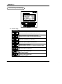
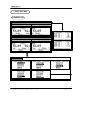
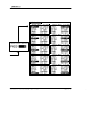
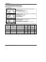
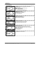
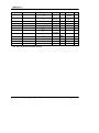
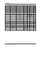
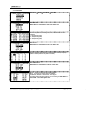
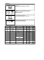
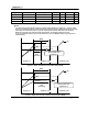
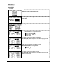
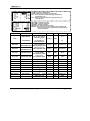
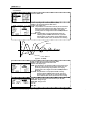
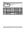
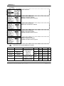
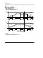
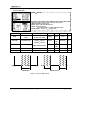
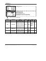
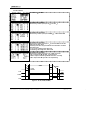
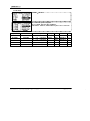
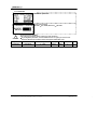
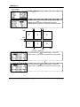
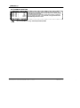
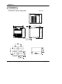
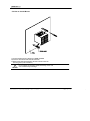
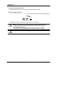
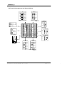
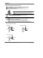
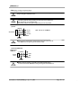
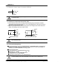
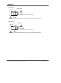
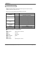
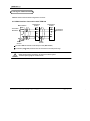
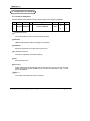
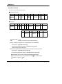
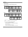
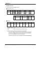
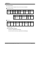
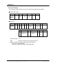
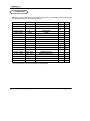
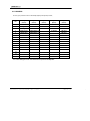
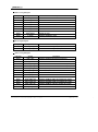
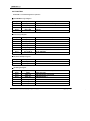
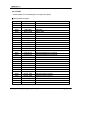
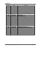
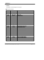
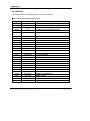
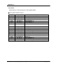
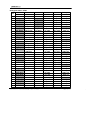
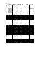
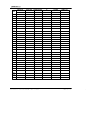
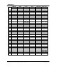
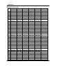
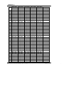
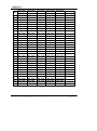
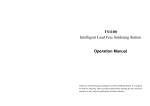
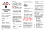
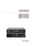
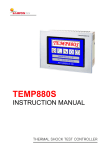
TEMI 300
INSTRUCTION MANUAL
TEMPERATURE HUMIDITY
PROGRAMMABLE CONTROLLER
Contents (
: User s Guide)
1. Safety Guide
4
2. Control Keys and Display
6
3. Basic Flow Map
7
4. Setting Up Parameter in Each Group
9
4.1 FIX Mode
9
4.2 PROG Run Screen
10
4.3 MAIN Screen Operation & Setting
12
4.3.1 Function
12
4.3.2 PROGRAM
15
4.3.3 RESERVE
18
4.3.4 GRAPH
19
4.4 SETUP Screen
20
4.4.1 INPUT
20
4.4.2 OUTPUT
22
4.4.3 ON/OFF
24
4.4.4 Inner Signal(IS)
26
4.4.5 ALARM
27
4.4.6 DO CONFIG
29
4.4.7 BIAS
32
4.4.8 DI NAME
34
4.4.9 PASSWORD
35
4.4.10 PID SET
36
4.5 TROUBLE SHOOTING
38
5. Installation
39
5.1 Dimension & Panel Cutting Size
39
5.2 How to Install Mount
40
5.3 Power Cable Specification
41
5.4 Terminal Specification
41
5.5 Terminal Arrangement and External Wiring
42
5.6 Grounding and Power Cable Connection
43
5.7 Analog Input Connection
43
5.8 Analog Output Connection
44
5.9 External Contact Output Connection(RELAY)
45
5.10 External Contact Input Connection(DI)
45
5.11 Use an Auxiliary Relay
45
Table 1 : Alarm Type
28
Figure 1 : Overshoot Suppressing by Fuzzy Function
12
12
17
17
22
25
26
28
29
32
36
Figure 2 : Ex. SLOPE Setting
Figure 3 : WAIT - Ex. Wait Function Release Within WTM
Figure 4 : WAIT - Ex. PV can t enter the wait zone within WTM
Figure 5 : AT GAIN
Figure 6 : Ex. ON/OFF MODE
Figure 7 : Ex. Inner Signal Zone
Figure 8 : Alarm Operation
Figure 9 : Ex. UP, SOAK, DOWN
Figure 10 : Ex. Piece Bias Formula
Figure 11 : PID Group
Contents (
: Communication User s Guide)
1. Communication Overview
47
2. Wiring for Communication
48
48
2.1 RS485 Interface Connection with TEMI 300
3. Configuration of Command
3.1 Consist of Command
3.2 Type of Command
3.3 Error Response
3.4 RSD Command
3.5 RRD Command
3.6 WSD Command
3.7 WRD Command
3.8 STD Command
3.9 CLD Command
4. D-REGISTER
4.1 PROCESS
4.2 FUNCTION
4.3 RESERVATION
4.4 IS/ALARM
4.5 PID
4.6 OUTPUT
4.7 INPUT
4.8 PROGRAM
4.9 ON/OFF
Enclosure D-Register
49
49
50
50
51
52
53
54
55
56
57
58
60
62
63
64
65
67
68
69
70
1. Safety Guide
The following safety symbols are used in this manual
(A) If this symbol is marked on the product, the operator must investigate the explanation given in this
manual to protect injury or death to personnel or damage to instrument.
(1) For Production : it should be marked when operator must refer the explanation in the
manual to avoid loss of life or damage to instrument.
!
CAUTION (2) For Instruction Manual : it marks to avoid operator s loss of life and injury that may result
comes from Electric Shock.
(B) Protective Ground Terminal
It marks the terminal must be connected to Ground prior to operating the equipment.
(C) It marks additional Information on the operation and features of the product.
?
NOTE
(D) It marks for further information on the current topic and pages
!
Precautions on this instruction Manual
!
Regarding Safety and Unauthorized Modification
CAUTION (1) This Manual should be passed on the end User and keep a suitable place for operator to
study and check the function of the product.
(2) Operator should carefully study, understand how to operate this product before
(3) This manual is describing the functions of the product. We, Samwontech, does not warrant
that the functions will suit a particular purpose.
(4) Under absolutely no circumstance may the contents of this manual in part or in whole be
transcribed or copied without permission.
(5) All contents of this manual has been made to ensure accuracy in the preparation, However,
should any errors or omissions come to the attention of the user, feel free to contact our
sales representatives or our sales office
CAUTION
!
CAUTION
(1) In order to protect this product and the system controlled by it against damage and ensure
its safe use, make certain that all of the safety instructions and precautions in this manual
are strictly adhered to.
(2) We, Samwontech, are not guarantee safety if the products are not handled according to
this instruction manuals
(3) If separate protection or safety circuits are to be installed for this product or the system
which is controlled by this product, ensure that such circuits are installed external to the
product.
(4) Don t try to make modifications or additions internal to the product. It may becomes
electric shock, burn or out of order.
(5) In case of replacement parts or consumables of the product, must call to our sales office.
(6) Protect this product from moisture. It may becomes out of order.
(7) Protect any kind of shock and vibration to the product. It may becomes product defects
and out of order
Regarding an exemption from responsibility
(1) Samwontech co. Ltd does not make any warranties regarding the product except Warranty
conditions those mentioned in this manual.
(2) We assumes no liability to any party for any loss or damage, direct or indirect, caused by
the use or any unpredictable defect of the product.
!
CAUTION
!
CAUTION
!
CAUTION
Regarding the production Quality Assurance.
(1) The guaranteed period of the production quality assurance is (1) one year after end user
buy it and it will be free to fix defected product under regular usage described
by this manual.
(2) It will be charged to fix defected product after warranty period. This charge will announced
by our actual cost to be calculated during the fixing time.
(3) It will be charging even if within warranty period as following events.
(3.1) Defect by operator and user s default.(forget password, production initialize)
(3.2) Natural disaster.(fire, water flow etc)
(3.3) Additional shift after 1st installed.
(3.4) Improperly repaired, or altered, modified in anyway.
(3.5) Power failure in unstable power condition.
(4) Feel free to contact our sales office whenever it need to make A/S.
Environmental precautions for installation.
(1) Be sure to operate the controller installed on a panel to prevent electric shock.
(2) To install the controller, do select a location where;
No one may accidentally touch terminal.
Mechanical vibrations are minimal.
No corrosive gas is prevent.
Temperature fluctuation is minimal.
Temperature can be maintained. (50
below / 10
over)
No direct heat radiation is present.
No magnetic disturbances are caused
No water is splashed.
No flammable materials are around.
No wind blows. (prevent Dust with salt)
No ultraviolet rays are present.
Pollution Degree 2
Installation Category II
Do not block openings
If the equipment is used in a manner not specified by the manufacturer,
the protection provided by the equipment may be impaired.
A switch or circuit-breaker acting as the disconnect device shall be included in the
application or the building installation
Precautions of Controller Mounting.
Keep the input circuit wiring as far as possible away from power and ground circuit.
Keep the controllers in 10 ~ 50 / 20 % ~ 90 % RH,
Warming up needed to use controller when temperature is below 10 in advance.
Do not mount front panel facing downward.
To prevent electric shock, be sure to turn off and the source circuit breaker before wiring.
The power consumptions are 100-240VAC, 50/60Hz, 15VAmax and operate without power
switching in advance.
No work in wet hands ( it caused electric shock)
Follow operation by precaution in the manual to avoid fire, electric shock, loss of life etc.
Requested to follow mounting and operation methods just indicated in this manual.
Refer the way of grounding connection, however, keep away for grounding to Gas pipe,
water pipe, lightening rod etc.
Be sure not to power connection before finishing of wiring between each contact point.
Not close and wrapping the heat hole in back case of controller.
2. Control Keys and Display
Control Keys
Key
Contents
Run / Stop controller (Pressing the key at least 3 sec.)
Switching between running and main menu page
Change the up level page on the parameter setting page
Switches to next page on the same level
Switches to previous page on the same level
Change to page on the menu
Switching between parameters or registering parameter settings
Move left / right on the parameter setting page
Shifting position to modify value
Decrease the value of parameters
Change to other available items
Move between GROUP
Increase the value of parameters
Change to other available items
Move between GROUP
3. Basic Flow Map
POWER ON
FIX MODE
TEMP & HUMI
TEMP Only
PROG MODE
TEMP & HUMI
TEMP Only
MAIN MENU
SETUP MENU
4. Setting Up Parameter in Each Group
4.1 FIX Mode
FIX Mode is controlling Temperature & Humidity with fixed SP
FIX STOP : Stop state
SP : Set point (Setting by SET key)
READY : Ready to running
Start running by RUN/STOP key
FIX running 1st screen
FIX RUNNING : Fix running state
PROCESS TIME : Running time
T : State of ON/OFF
IS : State of Inner Signal
FIX running 2nd screen
PV : Process value of temperature & humidity
MV : Manipulate value
RUN PID NUMBER : Running PID Number
(Display TEMP, HUMI AUTO TUNING when the auto tuning)
Symbol
Parameter
Display
Unit
Default
Edit
T.SP
TEMP SP
T.EU(0.0
Range
100.0%)
Always
T.EU
T.EU
(0.0%)
O
H.SP
HUMI SP
H.EU(0.0
100.0%)
When HUMI
OPER=ON
H.EU
H.EU
(0.0%)
O
P.TM
PROCESS TIME
00H00M
99H59M
Always
TIME
00H00M
X
T.MV
TEMP MV
0.0
100.0
Always
%
0.0%
X
H.MV
HUMI MV
0.0
100.0
When HUMI
OPER=ON
%
0.0%
X
R.PID
RUN PID NUMBER
Always
ABS
1
6
X
4.2 PROG Mode
PROG Mode is controlling Temperature & Humidity with
programmed data
PTNO : Set pattern No.(Set with SET key)
SEGNO : Start segment No.
READY : Ready to running
Start running by RUN/STOP key
PROG running 1st screen
PROG RUNNING : Prog running state
PROCESS TIME : Running time
RPT : Repeat pattern No.
PROG running 2nd screen
R.PID : Running PID No.(Figure3)
RM.TM : Remaind running time
PROG running 3rd screen
When HOLD ON, display held PT and SEG
When HOLD OFF, display running state
PROG running 4th screen
HOLD : HOLD ON or HOLD OFF with presents SP
STEP : Stop to present segment then step to next segment
DOWN : Going down zone
SOAK : Gong stable zone
UP : Going up zone
PATTERN END : Finished running
Symbol
Parameter
Display
Unit
Default
Edit
T.SP
TEMP SP
T.EU(0.0
100.0%)
Always
T.EU
T.EU
(0.0%)
X
H.SP
HUMI SP
H.EU(0.0
100.0%)
When HUMI
OPER=ON
H.EU
H.EU
(0.0%)
X
PTNO
PATTERN NUMBER
10
Always
ABS
0
O*note
SEGNO
SEGMENT NUMBER
100(00)
Always
ABS
0
X
P.TM
PROCESS TIME
Always
TIME
00H00M
X
RPT
PATTERN REPEAT
999
Always
ABS
0
X
T.MV
TEMP MV
100.0
Always
%
0.0%
X
100.0
When HUMI
OPER=ON
%
0.0%
X
X
X
H.MV
HUMI MV
Range
0
0
00H00M
0
0.0
0.0
99H59M
R.PID
RUN PID NUMBER
1
RM.TM
REMAIN TIME
00
HOLD
HOLD
OFF, ON
Always
ABS
OFF
O
STEP
STEP
OFF, ON
Always
ABS
OFF
O
*note : Edit is impossible while PROG operating
6
Always
ABS
99
Always
TIME
X
X
4.3 MAIN Screen Operation & Setting
4.3.1 FUNCTION
MENU KEY
FUNCTION
SET KEY
SUB SET setting
MAIN MENU FUNCTION SUB SET SET KEY
SUB SET1, SUB SET2 (PAGE UP/DOWN KEY)
OPER MODE : FIX / PROG
PWR MODE : State mode after power failure
Can be recognized over 3 sec. power failure
If power on within 3 sec. It is automatically running
with HOT mode
STOP : After power failure, go to STOP state
COLD : After power failure, go to RUN on fix running or
go to SEG1 on program running.
HOT : After power failure, running by previous data before
power failure.
KEY LOCK : Set key in possible / impossible
ON : Lock(Key in impossible)
OFF : Unlock(Key in possible)
BUZZER : Set buzzer sound ON/OFF
FUZZY : Set FUZZY ON/Off(Fuzzy : Overshoot suppressing function)
FIX OP TM : Set FIX Operation time ON/OFF
It is reserving function within 9999 hours and fix
running is finishing after set the time
TEMP(HUMI) SLOP : Set the slop for TSP, it is increase/decrease
to the target temp/humi gradually
Change SP
PV : FUZZY OFF
SP
SP=100
Temp gap 60
PV : FUZZY ON
60 /1min.
Rate up
=60/1=60( /min)
SP=40
Upping time 1min.
(Figure 1 : Overshoot suppressing function by FUZZY)
(Figure 2 : Ex. SLOPE setting)
Communication set
FUNCTION
MAIN MENU
COMM SET
SET KEY
HUMI OPER
SET KEY
PROT : Protocol
BPS : Speed (Bit per sec)
PRTY : Parity
S.BIT : Stop bit
D.LEN : Data length
ADDR : Address
RP.TM : Response time
Humi Oper
MAIN MENU
FUNCTION
HUMI OPER : ON
2-LOOP (Temperature/Humidity)
1-LOOP (Temperature)
OFF
AT TUNING set
FUNCTION
AT TUNING
SET KEY
MAIN MENU
AT TUNING is available on FIX RUN state only
Available on FIX RUN MODE only
AUTO TUNING with SP on FIX MODE only then after auto tuning the
value of tuning is saved on the correspond PID number
Symbol
Parameter
Range
Display
Unit
Default
Edit
OPER MODE
OPERATION MODE
PROG, FIX
Always
ABS
PROG
O
PWR MODE
POWER MODE
STOP, COLD, HOT
Always
ABS
STOP
O
KEY LOCK
KEY LOCK
OFF, ON
Always
ABS
OFF
O
BUZZER
BUZZER
OFF, ON
Always
ABS
ON
O
FUZZY
FUZZY
OFF, ON
Always
ABS
OFF
O
FIX OP TM.HR
FIX OP TIME(HOUR)
0
9999
Always
ABS
0
O
FIX OP TM.MIN
FIX OP TIME(MIN)
59
Always
ABS
0
O
FIX OP TM
FIX OP TIME
OFF, ON
Always
ABS
OFF
O
TEMP SLOP
TEMP SLOPE
T.EUS(0.0 100.0%)
/MIN
Always
T.EUS
/MIN
T.EUS(0.0%)
/MINUTE
O
HUMI SLOP
HUMI SLOPE
H.EUS(0.0 100.0%)
/MIN
Always
H.EUS
/MIN
H.EUS(0.0%)
/MINUTE
O
PROT
PROTOCOL
PCL0 (PC LINK),
PCL1 (PC with SUM)
Always
ABS
PCL0
O
0
BPS
BAUD RATE
600, 1200, 2400,
4800, 9600
Always
ABS
9600
O
PRTY
PARITY
NONE, EVEN, ODD
Always
ABS
NONE
O
S.BIT
STOP BIT
1, 2
Always
ABS
1
O
D.LEN
DATA LENGTH
7, 8
Always
ABS
8
O
ADDR
ADDRESS
Always
ABS
1
O
RP.TM
RESPONSE TIME
Always
ABS
0
O
HUMI OPER
HUMI OPER
ON, OFF
Always
ABS
ON
O
TEMP.AT
TEMP AUTO
TUNING
OFF, ON
On FIX
MODE
ABS
OFF
O
OFF, ON
On FIX
MODE
ABS
OFF
O
HUMI.AT
HUMI AUTO TUNING
1
99 (Max. 31unit)
0
10
4.3.2 PROGRAM
MENU KEY
MAIN
PROGRAM
EDIT SEG set
MAIN MENU
PROGRAM
SET KEY
EDIT SEG
SET KEY
Set the temperature, humidity, time, TS1, TS2 and TS3 for each
segment
1 : TS1(Time Signal1)
2 : TS2(Time Signal2)
3 : TS3(Time Signal3)
EDIT PT set
MAIN MENU
PROGRAM
EDIT PTN
SET KEY
Set the segment of the top/end, repeat (number of time) and jump
pattern number(wished link pattern number)
EDIT TIME SG set
PROGRAM
MAIN MENU
TIME SG
SET KEY
NO 0, 1 : These are only for ON or OFF function
NO 2 9 : These are only for time for ON/OFF
In the view, ON/OFF is selected for Time Signal
For define output by these setting, go and setting on MAIN MENU
PROGRAM EDIT SEG
SET KEY
WAIT SET set
PROGRAM
MAIN MENU
WAIT SET
SET KEY
TEMP ZONE : The range of temperature for waiting zone
HUMI ZONE : The range of humidity for waiting zone
WAIT TIME : Time for wait
WAIT USE : Use / Not use
Clear all of the patterns & segments
PROGRAM
ALL DEL
MAIN MENU
SET KEY
PT A.CLR : Clear all of the patterns
SEG A.CLR : Clear all of the segments
Symbol
Parameter
SG
SEGMENT NUMBER
Range
TEMP
TEMP SP
T.EU(0.0
HUMI
HUMI SP
H.EU(0.0
HH.MM
HOUR.MINUTE
-00.01(OFF)
1
TIME SIGNAL1
0(OFF)
2
TIME SIGNAL2
0(OFF)
3
TIME SIGNAL3
0(OFF)
PT
PATTERN NUMBER
01
TOP
START SEGMENT
1
01
Display
Unit
Default
Always
ABS
01
X
100.0%)
Always
T.EU
T.EU
(0.0%)
O
100.0%)
Always
H.EU
H.EU
(0.0%)
O
99.59
Always
ABS
-00.01(OFF)
O
9
Always
ABS
0(OFF)
O
9
Always
ABS
0(OFF)
O
9
Always
ABS
0(OFF)
O
10
Always
ABS
01
X
100
Always
ABS
0
O
Always
ABS
0
O
Always
ABS
1
O
Always
ABS
0
O
100(01,02,
,99,00)
TOP END
Edit
END
END SEGMENT
RPT
REPEAT SEGMENT
0(0= )
JP
JUMP PATTERN
0
TEMP ZONE
TEMP WAIT ZONE
T.EUS(0.0
100.0%)
Always
T.EUS
T.EUS
(0.0%)
O
HUMI ZONE
HUMI WAIT ZONE
H.EUS(0.0
100.0%)
Always
H.EUS
H.EUS
(0.0%)
O
999
10
Symbol
Parameter
WAIT TIME
WAIT TIME(HH.MM)
Range
Display
Unit
Default
Edit
Always
ABS
0.00
WAIT USE
WAIT USE
O
ON, OFF
Always
ABS
OFF
PT A.CLR
O
ALL PATTERNS DELETE
OFF, ON
Always
ABS
OFF
SEG A.CLR
O
ALL SEGMENTS DELETE
OFF, ON
Always
ABS
OFF
O
0.00
99.59
Wait
The wait function holds off the transition of segment until deviation is cleared up. The use of this
function is enabled by defining a wait zone that is a deviation range to determine the follow-up of PV
data input, and a wait time, which is a period of waiting time until PV data enters the wait zone.
When PV input enters the wait zone within the wait time, the operation shifts to the next.
If not, the shift takes place as soon as the wait time is over, The WTM should be set for prevent to
infinite waiting
WTM
SP
WZ
WZ
PV
The time on release waiting,
Running with next
segment(n+1)
Running
Wait
(Time stop)
Segment_n
Segment_(n+1)
Segment_(n+2)
(Figure 3 : WAIT - Ex. Wait Function Release Within WTM)
WTM
SP
WZ
WZ
PV
Running
Wait
(Time stop)
Segment_n
Segment_(n+1)
(Figure 4 : WAIT - Ex. PV can
The time on release waiting,
Running with next
segment(n+1)
Segment_(n+2)
t enter the wait zone within WTM)
4.3.3 RESERVE
RESERVE set
MAIN
MENU KEY
RESERVE
SET KEY
NOW : Display present year, month, date and time which is set on
SET DATE area
RUN DATE : Set reserved starting year, month, date and time
SET DATE : Set present year, month, date and time
RESERVE : Use/not use
Symbol
Parameter
Range
Display
Unit
Default
Y
YEAR
0
99
Always
ABS
1
M
MONTH
1
12
Always
ABS
1
D
DAY
1
31
Always
ABS
1
1
H
HOUR
0
23
Always
ABS
M
MINUTE
0
59
Always
ABS
1
RESERVE
RESERVE SET
Always
ABS
OFF
OFF, ON
Edit
O
(Except
Now
date)
X
4.3.4 GRAPH
GRAPH set
MENU KEY
MAIN
GRAPH
SET KEY
Display segment on pattern by graph for temperature & humidity
PTN : Set the pattern No. for wished see
SEG : Set the segment No. for display starting
Symbol
Parameter
Range
Display
Unit
Default
Edit
PTN
PATTERN NUMBER
1
10
Always
ABS
Set PT on
MAIN
O
SEG
SEGMENT
NUMBER
1
99
Always
ABS
Set SEG on
PT
X
T.SP
TEMP SP
100.0%)
Always
T.EU
X
X
100.0%)
HUMI OPER
= ON
H.EU
X
X
H.SP
HUMI SP
T.EU(0.0
H.EU(0.0
4.4 SETUP
4.4.1 INPUT
SETUP set.
MENU KEY
MAIN
SETUP
SET KEY
Illuminate No.
SET KEY
INPUT
SET KEY
Password with UP, DOWN, SHIFT KEY
SET KEY
TYPE : Set sensor type for temperature (PT-1, PT-2 or DCV)
Resolution of PT-1 is higher than PT-2's
RNG.HIGH/LOW : Rang of using temperature
PT-1 : -50.00 150.00
PT-2 : -100.0 200
DCV : 1 5V
It is shown, sensor type is DCV for temperature
SCL.HIGH(LOW) : Set the input range scale when input type is DCV
200.0
SCALE : -100.0
TYPE : Set sensor type for humidity (PT or DCV)
RNG.HIGH(LOW) : Rang of using Humidity
PT : -10.0 110.0%
DCV : 1 5V
It is shown, sensor type is DCV for humidity
SCL.HIGH(LOW) : Set the input range scale when input type is DCV
SCALE : 0.0
100.0%
T.BIAS : Set bias for temperature
H.BIAS : Set bias for humidity high-frequency
T.FL : Set for protect any effect from high frequency to
temperature input
H.FL : Set for protect any effect from high frequency to
humidity input
DRY TEMP : Temp of dry probe.
WET TEMP : Temp of wet probe.
HUMIDITY : Relative humidity.
WET ADJUST : Adjust temp of wet part.
ADJUST : Using when the temp of dry/wet part are RTD TYPE
Temp of dry part and wet part are being same temp as
select this button.
Symbol
Parameter
Range
TEMP SENSOR
PT_1(-50.00 150.00)
PT_2(-100.0 200.0)
DCV(1.000 5.000)
TYPE
Display
Unit
Always
ABS
Default
Edit
PT_1
O
HUMI SENSOR
PT(-10.0 110.0)
DCV(1.000 5.000)
RNG.HIGH
TEMP RANGE HIGH
HUMI RANGE HIGH
T.EU(0.0 100.0%)
RNG.LOW<RNG.HIGH
Always
T.EU
H.EU
T.EU(100.0%)
H.EU(100.0%)
O
RNG.LOW
TEMP RANGE LOW
HUMI RANGE LOW
H.EU(0.0 100.0%)
RNG.LOW<RNG.HIGH
Always
T.EU
H.EU
T.EU(0.0%)
H.EU(0.0%)
O
SCL.HIGH
TEMP SCALE HIGH
HUMI SCALE HIGH
-100.0
200.0
SCL.LOW<SCL.HIGH
TYPE =
DCV
ABS
200.0
100.0%
O
SCL.LOW
TEMP SCALE LOW
HUMI SCALE LOW
0.0
100.0%
SCL.LOW<SCL.HIGH
TYPE =
DCV
ABS
-100.0
0.0%
O
T.EUS(-100
Always
T.EUS
T.EUS(0.0%)
O
Always
ABS
0 SEC
O
Always
H.EUS
H.EUS(0.0%)
O
Always
ABS
0 SEC
O
100%)
PT
T.BIAS
TEMP BIAS
T.FL
TEMP FILTER
0
H.BIAS
HUMI BIAS
H.EUS(-20
H.FL
HUMI FILTER
0
DRY TEMP
DRY TEMP
T.EU(-5.0
105.0%)
Always
T.EU
X
X
WET TEMP
WET TEMP
W.EU(0.0
100.0%)
Always
W.EU
X
X
HUMIDITY
HUMIDITY
H.EU(0.0
100.0%)
Always
H.EU
X
X
WET ADJUST
WET ADJUST
H.EUS(-100.0
Always
H.EUS
H.EUS(0.0%)
O
ADJUST
ADJUST
Always
ABS
NONE
O
120s
20%)
120s
100.0%)
NONE, EXE, CLR
4.4.2 OUTPUT
OUTPUT
SET KEY
TYPE : Output type for control temperature (SSR)
DIRECT : Set reverse/forward for PID control
CYCLE : Set output cycle
ARW : The parameter to set deviation width to prevent overshoot.
When the control output reaches High-Limited value, for
preventing Overshoot by integral action, It is stoping
ordinary action for integrals and shift for ARW(Anti-Reset
Wind-Up)
AT GAIN : The parameter to set proportional PID control by
obtaining AUTO TUNING. Reduce AT-G, Cycle time
became rapid. Increase AT-G, control status became
more stable. Smaller value, will become more hunting
Gain < 1
Gain = 1
Gain > 1
(Figure 5 : AT GAIN)
TYPE : Output type for control temperature (SSR)
DIRECT : Set reverse/forward for PID control
CYCLE : Set output cycle
ARW : The parameter to set deviation width to prevent overshoot.
When the control output reaches High-Limited value, for
preventing Overshoot by integral action, It is stoping
ordinary action for integrals and shift for ARW(Anti-Reset
Wind-Up).
AT GAIN : The parameter to set proportional PID control by
obtaining AUTO TUNING. Reduce AT-G, Cycle time
became rapid. Increase AT-G, control status became
more stable. Smaller value, will become more hunting
KIND : Set type of temperature retransmission (PV, SP, MV)
RNG.HIGH : Range of high
RNG.LOW : Range of low
PV : PV
SP : SP
MV : MV
KIND : Set type of humidity retransmission (PV, SP, MV)
RNG.HIGH : Range of high
RNG.LOW : Range of low
PV : PV
SP : SP
MV : MV
Symbol
Parameter
Range
Display
Unit
Default
Edit
DIRECT
TEMP DIRECT
HUMI DIRECT
REVERSE, FORWARD
Always
ABS
REVERSE
O
CYCLE
TEMP CYCLE
HUMI CYCLE
1
Always
ABS
1
O
ARW
ANTI RESET
Wind-Up Select
0.0, 50.0
Always
ABS
0.0
O
0.1
300
200.0
AT GAIN
AT GAIN
10.0
Always
ABS
1.0
O
KIND
RETRANSMISSION
PV, SP, MV
Always
ABS
PV
O
RNG.HIGH
TEMP RANGE HIGH
HUMI RANGE HIGH
T.EU(0.0
100.0%)
RNG.LOW<RNG.HIGH
PV, SP
T.EU
H.EU
T.EU(100.0%)
H.EU(100.0%)
O
RNG.LOW
TEMP RANGE LOW
HUMI RANGE LOW
H.EU(0.0
100.0%)
RNG.LOW<RNG.HIGH
PV, SP
T.EU
H.EU
T.EU(0.0%)
H.EU(0.0%)
O
4.4.3 ON/OFF
ON/OFF
SET KEY
ON/OFF mode for temperature
HIGH.SP : Set low SP on ON/OFF
HIGH.DIFF : Deviation value for high zone
ON/OFF mode for temperature
MIDDLE.SP : Set middle SP on ON/OFF
ON/OFF mode for temperature
LOW.SP : Set low SP on ON/OFF
LOW.DIFF : Deviation value for low zone
ON/OFF mode for humidity
HIGH.SP : Set high SP on ON/OFF
LOW.DIFF : Deviation value for high zone
?
NOTE
HIGH.SP must be set before MIDDLE.SP or LOW.SP
Symbol
Parameter
Range
Display
Unit
Default
Edit
LOW.SP
LOW SP
T.EU(0.0 100.0%)
H.EU(0.0 100.0%)
Always
T.EU
H.EU
T.EU(0.0%)
H.EU(0.0%)
O
MIDDLE.SP
MIDDLE SP
Always
T.EU
H.EU
T.EU(0.0%)
H.EU(0.0%)
O
T.EU(0.0%)
H.EU(0.0%)
O
RL LOW.SP
<MIDDLE.SP
HIGH.SP
HIGH SP
Always
T.EU
H.EU
10.0%)
10.0%)
Always
T.EUS
H.EUS
T.EUS(0.0%)
H.EUS(0.0%)
O
10.0%)
10.0%)
Always
T.EUS
H.EUS
T.EUS(0.0%)
H.EUS(0.0%)
O
<HIGH.SP RH
HIGH.DIFF
HIGH DIFFERENCE
T.EUS(0.0
H.EUS(0.0
LOW.DIFF
LOW DIFFERENCE
T.EUS(0.0
H.EUS(0.0
1. T1
T3, H1 (ON after set time, the set time adapted on first ON state at running)
NPV < LSP(LOW.SP)
Output : OFF
NPV > HSP(HIGH.SP)
Output : OFF
LSP NPV < MSP(MIDDLE.SP)
NPV NSP-LD(LOW.DIFF)
Output : ON
NPV < NSP-LD
Output : OFF
MSP < NPV < HSP,
NPV < NSP +HD(HIGH.DIFF)
Output : OFF
NPV NSP + HD
Output : ON
MSP
NPV
NSP
LD=3
LSP
ON
Set time
ON
OFF
ON
OFF
ON
OFF
HSP
NSP
HD=3
MSP
NPV
ON
ON
OFF
ON
OFF
Set time
(Figure 6 : ON/OFF MODE)
2. T4 output
T4 is turning on after set delay time after T3 turned on
T4 is turning off together when T3 turn off
ON
OFF
OFF
4.4.4 Inner Signal(IS)
INNER
SET KEY
KIND : Set type of humidity retransmission (PV, SP, MV)
RNG.HIGH(LOW) : Range for IS
BAND : Direct of IS band (IN.B/OUT.B)
DELAY. TM : IS delay time
IS1 connected with 1ST REF, 2ND REF output
INNER SIGNAL : There are 1
6 pages of IS
Symbol
Parameter
Range
KIND
INNER SIGNAL
KIND
T.TSP, T.PV, T.SP
H.TSP, H.PV, H.SP
RNG.HIGH
IS RANGE HIGH
T.EU(0.0
100.0%)
H.EU(0.0
100.0%)
RNG.LOW
IS RANGE LOW
BAND
BAND DIRECT
DELAY.TM
DELAY TIME
RL(
,%) RNG.LOW
IS run
Unit
Default
Edit
Always
ABS
T.SP
O
EU(0.0%)
O
EU(0.0%)
O
Always
T.EU
H.EU
T.EU
RNG.LOW<RNG.HIGH
Always
IN.B, OUT.B
Always
ABS
IN.B
O
Always
ABS
00.00
O
00.00
RNG.HIGH
Display
RH(
99.59 MM.SS
,%)
RL(
,%) RNG.LOW
H.EU
RNG.HIGH
IS run
A)BAND=IN.B
IS run
B)BAND=OUT.B
(Figure 7 : Ex. Inner Signal Zone)
RH(
,%)
4.4.5 ALARM
ALARM
SET KEY
ITEM : Set item of alarm
KIND : Set type of alarm
POINT : Set alarm point
HYS. : Set hysteresis for alarm
DELAY.TM : Set the delay time for alarm output
ALARM SIGNAL : There are 1
4 pages of alarm
?
NOTE
Alarm is working on even STOP state
Symbol
Parameter
Range
Display
Unit
Default
Edit
ITEM
ALARM ITEM
TEMP, HUMI
Display
ABS
TEMP
O
Display
ABS
AH.F, AL.F, DH.F, DL.F
DH.R, DL.R, DO.F, DI.F
KIND
ALARM KIND
AH.R, AL.R, AH.FS
AL.FS, DH, FS, DL.FS
DH.RS, DL.RS, DO.FS
ALARM 1, 3
AH.F
ALARM 2, 4
AL.F
O
DI.FS, AH.RS, AL.RS
POINT
ALARM POINT
HYS.
ALARM
HYSTERESIS
DELAY.TM
DELAY TIME
T.EU(-100.0
100.0%)
H.EU(-100.0
100.0%)
T.EUS(0.0
100.0%)
H.EUS(0.0
100.0%)
00.00
99.59 M.S
Display
Display
Display
T.EU
H.EU
T.EUS
H.EUS
ABS
EU(100.0%)
O
EUS(0.5%)
O
00.00
O
(Table 1 : Alarm Type)
No.
Alarm Type
1
2
3
4
5
6
7
8
9
10
11
12
13
14
15
16
17
18
19
20
PV Upper-Limit
PV Lower-Limit
Deviation Upper-Limit
Deviation Lower-Limit
Deviation Upper-Limit
Deviation Lower-Limit
Deviation Upper & Lower-Limit
Deviation Upper & Lower-Limit Range
PV Upper-Limit
PV Lower-Limit
PV Upper-Limit
PV Lower-Limit
Deviation Upper-Limit
Deviation Lower-Limit
Deviation Upper-Limit
Deviation Lower-Limit
Deviation Upper & Lower-Limit
Deviation Upper & Lower-Limit Range
PV Upper-Limit
PV Lower-Limit
Output Direct
For
Rev
O
O
O
O
O
O
O
O
O
O
O
O
O
O
O
O
O
O
O
O
Standby
On
Off
O
O
O
O
O
O
O
O
O
O
O
O
O
O
O
O
O
O
O
O
Display Data
AH.F
AL.F
DH.F
DL.F
DH.R
DL.R
DO.F
DI.F
AH.R
AL.R
AH.FS
AL.FS
DH.FS
DL.FS
DH.RS
DL.RS
DO.FS
DI.FS
AH.RS
AL.RS
ON
PV Upper
Limit
ON
DB
PV
Deviation
Upper Limit
OFF
ALM
DEV
SP
ON
PV lower
Limit
PV
Deviation
Lower Limit
OFF
DEV
SP
ON
Within
Deviation
Upper and
Lower Limit
OFF
ALM
DB
OFF
+
DB
OFF
ALM
DB
DEV=0
SP
ON
DEV
-
ALM
ON
DB
DEV
-
OFF
ON
DB
ALM
Deviation
Upper and
Lower Limit
DB
OFF
+
ON
DB
DEV=0
ALM
ALM
SP
ALM
(Fig 8 : Alarm Operation)
OFF
+
+
4.4.6 DO CONFIG
DO CONFIG
SET KEY
DO CONFIG set (1st page)
Set the relay number (1~12) for IS1
6 and TS1
DO CONFIG set (2nd page)
Set the relay number (1~12) for ALARM1
3
4, T.RUN and H.RUN
DO CONFIG set (3rd page)
Set the relay number (1~12) for T1 T4, and H1.RUN also set the
delay time for each items
The delay time effect only first ON time and next ON is not effect
from delay time
T1, T2, T3, H1 : Working after delay time
T4 : Working after delay time, after T3 ON
DO CONFIG set (3rd page)
Set the relay number (1~12) for T.UP, T.SOK, and T.DN
T.UP : Output until X [X=TSP - set temperture]
T.SOK : Output until X min [X=SOAK zone time - set time]
T.DN : Output until X [X=T.SP - set temperature]
UP
SOAK
T.UP
T.SOK
DOWN
T.SOK
set time
T.UP
set time
ON
T.DN
set time
ON
ON
T.DN
(Figure 9 : Ex. UP, SOAK, DOWN)
DO CONFIG set (5th page)
Set the relay number (1~12) for H.UP, H.SOK, and H.DN
H.UP : Output until X% [X=TSP - set humidity]
H.SOK : Output until X min [X=SOAK zone time - set time]
H.DN : Output until X% [X=T.SP - set humidity]
DO CONFIG set (6th page)
DRAIN : Output on the zone that humidity is not used
ERROR : Output in set time when DI2 DI4 is occur
PTEND : Output in set time when program finish
1_REF, 2_REF : Output after set time when IS1 is working
It is useful for Refrigerator 1, 2
Symbol
Parameter
Display
Unit
Default
Edit
IS1
INNER SIGNAL1
0
120 (0 : OUTPUT OFF)
Range
Always
ABS
0
O
IS2
INNER SIGNAL2
0
120 (0 : OUTPUT OFF)
Always
ABS
0
O
IS3
INNER SIGNAL3
0
120 (0 : OUTPUT OFF)
Always
ABS
0
O
IS4
INNER SIGNAL4
0
120 (0 : OUTPUT OFF)
Always
ABS
0
O
IS5
INNER SIGNAL5
0
120 (0 : OUTPUT OFF)
Always
ABS
0
O
IS6
INNER SIGNAL6
0
120 (0 : OUTPUT OFF)
Always
ABS
0
O
TS1
TIME SIGNAL1
0
120 (0 : OUTPUT OFF)
Always
ABS
0
O
TS2
TIME SIGNAL2
0
120 (0 : OUTPUT OFF)
Always
ABS
0
O
TS3
TIME SIGNAL3
0
120 (0 : OUTPUT OFF)
Always
ABS
0
O
AL1
ALARM SIGNAL1
0
120 (0 : OUTPUT OFF)
Always
ABS
0
O
AL2
ALARM SIGNAL2
0
120 (0 : OUTPUT OFF)
Always
ABS
0
O
AL3
ALARM SIGNAL3
0
120 (0 : OUTPUT OFF)
Always
ABS
0
O
AL4
ALARM SIGNAL4
0
120 (0 : OUTPUT OFF)
Always
ABS
0
O
T.RUN
TEMP RUN
0
120 (0 : OUTPUT OFF)
Always
ABS
0
O
H.RUN
HUMI RUN
0
120 (0 : OUTPUT OFF)
Always
ABS
0
O
T1
T1 SIGNAL
0
120 (0 : OUTPUT OFF)
Always
ABS
0
O
T1 PARA
T1 SIGNAL PARA
0.00
Always
ABS
00.00
O
T2
T2 SIGNAL
120 (0 : OUTPUT OFF)
Always
ABS
0
O
T2 PARA
T2 SIGNAL PARA
0.00
Always
ABS
00.00
O
T3
T3 SIGNAL
120 (0 : OUTPUT OFF)
Always
ABS
0
O
T3 PARA
T3 SIGNAL PARA
0.00
Always
ABS
00.00
O
T4
T4 SIGNAL
120 (0 : OUTPUT OFF)
Always
ABS
0
O
T4 PARA
T4 SIGNAL PARA
0.00
Always
ABS
00.00
O
H1
H1 SIGNAL
120 (0 : OUTPUT OFF)
Always
ABS
0
O
H1 PARA
H1 SIGNAL PARA
0.00
Always
ABS
00.00
O
0
0
0
0
99.59 MM.SS
99.59 MM.SS
99.59 MM.SS
99.59 MM.SS
99.59 MM.SS
Symbol
Parameter
T.UP
TEMP UP SIGNAL
T.UP PARA
TEMP UP PARA
T.SOK
TEMP SOAK SIGNAL 0
T.SOK PARA
TEMP SOAK PARA
T.DN
TEMP DOWN SIGNAL
T.DN PARA
TEMP DOWN PARA
H.UP
HUMI UP SIGNAL
H.UP PARA
HUMI UP PARA
H.SOK
HUMI SOAK SIGNAL
H.SOK PARA
HUMI SOAK PARA
H.DN
HUMI DOWN PARA
DRAIN
DRAIN SIGNAL
DRAIN PARA
DRAIN PARA
ERROR
ERROR SIGNAL
ERROR PARA
ERROR PARA
PTEND
PTEND SIGNAL
PTEND PARA
PTEND PARA
0
FIRST REF. PARA
2_REF
SECOND REFERENCE
SIGNAL
2_REF PARA
SECOND REF. PARA
Unit
Default
Edit
Always
ABS
0
O
T.EUS(0.0
Always
T.EUS
T.EUS
(0.0%)
O
Always
ABS
0
O
999 MIN
Always
ABS
0
O
120 (0 : OUTPUT OFF)
Always
ABS
0
O
Always
T.EUS
T.EUS
(0.0%)
O
Always
ABS
0
O
Always
H.EUS
H.EUS
(0.0%)
O
0
O
Always
ABS
999 MIN
Always
ABS
0
O
120 (0 : OUTPUT OFF)
Always
ABS
0
O
Always
H.EUS
H.EUS
(0.0%)
O
Always
ABS
0
O
999 MIN
Always
ABS
0
O
120 (0 : OUTPUT OFF)
Always
ABS
0
O
999 MIN
Always
ABS
0
O
120 (0 : OUTPUT OFF)
Always
ABS
0
O
999 MIN
Always
ABS
0
O
120 (0 : OUTPUT OFF)
H.EUS(0.0
0
0
0
Always
ABS
0
O
999 SEC
Always
ABS
0
O
120 (0 : OUTPUT OFF)
Always
ABS
0
O
Always
ABS
0
O
0
0
100.0%)
120 (0 : OUTPUT OFF)
0
0
100.0%)
120 (0 : OUTPUT OFF)
0
0
100.0%)
120 (0 : OUTPUT OFF)
H.EUS(0.0
0
100.0%)
120 (0 : OUTPUT OFF)
T.EUS(0.0
0
FIRST REFERENCE
0
SIGNAL
1_REF PARA
Display
120 (0 : OUTPUT OFF)
0
HUMI DOWN SIGNAL 0
H.DN PARA
1_REF
Range
0
0
999 MIN
4.4.7 BIAS SET
BIAS SET
SET KEY
Set bias for dry temperature
P : Point (Boundary point)
D : Bias value
d
Actual
Temperature
c
P=RH
D=d
P=P2
D=c
b
P=P1
D=b
a
RL
P=RL
D=a
Temperature
after Bias
P1
(Figure 10 : Ex. Piece Bias Formula)
Set bias for wet humidity
P : Point (Boundary point)
D : Bias value
Set bias for relative humidity
P : Point (Boundary point)
D : Bias value
P2
RH
Symbol
DP.RL
DP.P1
DP.P2
DP.PH
DD.RL
DD.P1
DD.P2
DD.RH
DRY TEMP
WP.RL
WP.P1
WP.P2
WP.RH
WD.RL
WD.P1
WD.P2
WD.RH
W
RP.RL
RP.P1
RP.P2
RP.RH
RD.RL
RD.P1
RD.P2
RD.RH
RH
Parameter
TEMP REFERENCE
BIAS RL
TEMP REFERENCE
BIAS POINT1
TEMP REFERENCE
BIAS POINT2
TEMP REFERENCE
BIAS RH
TEMP BIAS VALUE
OF RL
TEMP BIAS VAUE
OF POINT1
TEMP BIAS VALUE
OF POINT2
TEMP BIAS VALUE
OF RH
DRY TEMP
WET TEMP REF.
BIAS RL
WET TEMP REF.
BIAS POINT1
WET TEMP REF.
BIAS POINT2
WET TEMP REF.
BIAS RH
WET TEMP BIAS
VALUE OF RL
WET TEMP BIAS
VAUE OF POINT1
WET TEMP BIAS
VAUE OF POINT2
WET TEMP BIAS
VALUE OF RH
WET TEMP
HUMIDITY REF.
BIAS RL
HUMIDITY REF.
BIAS POINT1
HUMIDITY REF.
BIAS POINT2
HUMIDITY REF.
BIAS RH
HUMIDITY BIAS
VALUE OF RL
HUMIDITY BIAS
VAUE OF POINT1
HUMIDITY BIAS
VALUE OF POINT2
HUMIDITY BIAS
VALUE OF RH
HUMIDITY
Range
T.EU(0.0
100.0%)
Display
Unit
Default
Edit
Always
T.EU
T.EU
(0.0%)
O
T.EU
T.EU
(100.0%)
O
T.EU
T.EU
(100.0%)
O
Always
T.EU
T.EU
(100.0%)
O
Always
T.EUS
T.EUS(0.0%)
O
Always
T.EUS
T.EUS(0.0%)
O
Always
T.EUS
T.EUS(0.0%)
O
Always
T.EUS
T.EUS(0.0%)
O
Always
T.EU
X
X
Always
W.EU
W.EU(0.0%)
O
Always
W.EU
W.EU
(100.0%)
O
W.EU
W.EU
(100.0%)
O
W.EU
W.EU
(100.0%)
O
Always
RL DP.RL<DP.P1
<DP.P2<DP.RH RH
T.EUS(-10.0
T.EU(0.0
Always
10.0%)
100.0%)
W.EU(0.0
100.0%)
RL WP.RL<WP.P1
<WP.P2<WP.RH RH
Always
Always
W.EUS(-10.0
W.EU(0.0
H.EU(0.0
Always
W.EUS W.EUS(0.0%)
O
Always
W.EUS W.EUS(0.0%)
O
Always
W.EUS W.EUS(0.0%)
O
Always
W.EUS W.EUS(0.0%)
O
10.0%)
100.0%)
100.0%)
Always
W.EU
X
X
Always
H.EU
H.EU(0.0%)
O
Always
H.EU
H.EU
(100.0%)
O
H.EU
H.EU
(100.0%)
O
Always
H.EU
H.EU
(100.0%)
O
Always
H.EUS
H.EUS(0.0%)
O
Always
H.EUS
H.EUS(0.0%)
O
Always
H.EUS
H.EUS(0.0%)
O
Always
H.EUS
H.EUS(0.0%)
O
Always
H.EU
X
X
RL RP.RL<RP.P1
<RP.P2<RP.RH RH
H.EUS(-10.0
H.EU(0.0
Always
10.0%)
100.0%)
4.4.8 DI NAME
DI NAME
SET KEY
DI1 : RUN/STOP
Not changeable
DI2, 3, 4 NAME : SET KEY
UP, DOWN key
TOG GROUP : PAGE UP, PAGE DOWN key when name is illuminate
Symbol
Parameter
Range
Display
Unit
Default
DI1 NAME
DI1 NAME
RUN/STOP
Always
ABS
RUN/STOP
Edit
X
DI2 NAME
DI2 NAME
0
9, A
Z, Symbols
Always
ABS
ERROR 02
O
DI3 NAME
DI3 NAME
0
9, A
Z, Symbols
Always
ABS
ERROR 03
O
DI4 NAME
DI4 NAME
0
9, A
Z, Symbols
Always
ABS
ERROR 04
O
TOG GROUP
TOG GROUP
0
9, A
Z, Symbols
Always
ABS
ABCD
X
4.4.9 PASSWORD
PASSWORD
SET KEY
Set the new password
SET KEY
UP, DOWN, SHIFT key
!
CAUTION
Symbol
PASSWORD
SET KEY
Default password is 0(ZERO)
After changing password, please confirm your new password
If you forget the password, connect Samwontech or our agency for reset service
All of the data that you set before will be changed to default after reset
Parameter
PASSWORD
SETTING
Range
0
9999
Display
Unit
Default
Edit
Always
ABS
0
O
4.4.10 PID SET
PID SET
SET KEY
TEMP.RP1, RP2 : Boundary value on temperature span for PID
zone
HUMI.RP : Boundary value on humidity span for PID zone
TEMP, HUMI.HYS : Hysteresis for temperature/humidity PID ZONE
T.HYS
T.HYS
HUMI
2
4
6
1
3
5
H.RP
H.HYS
RL
T.RP1
T.RP2
RH
TEMP
(Figure 11 : PID Group)
T.P/T,I/T.D/H.P/H.I/H.D : Temperature/Humidity P, I, D value for
PID 1
T(H)OH, T(H)OL : High/low value for temperature/humidity for MV
T.P/T,I/T.D/H.P/H.I/H.D : Temperature/Humidity P, I, D value for
PID 6
T(H)OH, T(H)OL : High/low value for temperature/humidity for MV
Symbol
Parameter
TEMP.RP1
TEMP REFERENCE1
TEMP.RP2
TEMP REFERENCE2
HUMI.RP
HUMI REFERENCE
Range
0.1
Display
Unit
Default
Display
ABS
33.3
O
Display
ABS
66.7
O
Display
H.EU
50.0%
O
T.EUS
T.EUS
(0.3%)
O
Display
H.EUS
H.EUS
(0.3%)
O
999.9
Display
ABS
5.0
O
RP2-1digit
RP1+1digit
RL+1digit
RH-1digit
T.EUS(0.0
TEMP.HYS
T.REF HYSTERESIS
HUMI.HYS
H.REF
HYSTERESIS
T.P
PROPORTIONAL
BAND
0.1
99.9
10.0%)
H.EUS(0.0
10.0%)
Display
Edit
T.I
TEMP INTEGRAL
0
6000
Display
ABS
120
O
T.D
DERIVATIVE TIME
0
6000
Display
ABS
30
O
TOH
TEMP OUTPUT
LIMIT HIGH
T.OL+1digit
Display
ABS
100.0
O
T.OL
TEMP OUTPUT
LIMIT LOW
T.OH-1digit
Display
ABS
0.0
O
H.P
PROPORTIONAL
BAND
0.1
999.9
Display
ABS
5.0
O
H.I
HUMI INTEGRAL
0
6000
Display
ABS
120
O
H.D
DERIVATIVE TIME
0
6000
Display
ABS
30
O
HOH
HUMI OUTPUT
LIMIT HIGH
0.0
100.0
Display
ABS
100.0
O
HOL
HUMI OUTPUT
LIMIT LOW
0.0
100.0
Display
ABS
0.0
O
0.0
100.0
4.5 TROUBLE SHOOTING
If the system, which this controller (NOVA series) adapted, has
troubles (if you used DI2~DI4), the page appear also display WARN
at the item state as picture
You must solve the error before reusing the controller, otherwise
you are reach error again. The controller is being the STOP mode
automatically when error occur
?
NOTE
Ref 4.4.8 DI NAME for change TROUBLE(DI ERROR) NAME
5. Installation
5.1 Dimension & Panel Cutting Size
91.6
(Unit : mm)
96
91.6
99.6
1mm~10mm
(PANEL Thickness)
N : Total unit
107.5
11.4
96
5.2 How to install Mount
1) Cut the mounting panel as Section 5.1 PANEL CUTTING
2) Insert the unit from its back terminal board side
3) Attach the left and right brackets to the unit to fix the unit to the
mounting panel. (Use screwdriver)
!
CAUTION
Do not tighten the mounting screw excessively, or the unit
case or bracket may be damage
5.3 Power Cable Specification
Applicable power source cable : Vinyl insulation cable KSC 3304 0.9~2.0
5.4 Terminal Specification
Please use-tightening torque with insulating sleeve for M3.5 screws as shown in the following Figure:
3.0 or
more
Note: When the screw is connected, its torque does not exceed 0.8 N m.
!
CAUTION
!
CAUTION
CAUTION
Before carrying out wiring, turn off the power to the controller and check that the
cables to be connected are not alive with a tester or the like because there is a
possibility of electric shock
The controller must be wired directly from circuit breaker output on inside of
temperature & humidity Chamber for avoid damage of controller or chamber
Avoid unused terminal for install, it might make damage to system or out of order
5.5 Terminal Arrangement and External Wiring
DO
RELAY
41
DO1
31 RLY1
42
DO2
32 RLY2
43
DO3
33 RLY3
44
DO4
34 RLY4
45
COM
35 COM
Capacity :
Less then 24VDC 50mA
Capacity : 250V AC 1A
30V DC 1A
RS485
RTX+ 1
11
OUT1(+) SSR
12
OUT2(+) SSR
11
41
31
1
13
COM(-)
12
42
32
2
SG
13
43
33
3
MAX:9600bps
14
44
34
4
15
45
35
5
16
46
36
6
14
AOUT1(+)
15
AOUT1(-)
16
AOUT2(+)
17
47
37
7
17
AOUT2(-)
18
48
38
8
RET 4~20mA DC
19
49
39
9
20
50
40
10
POWER
18
19
20
N
GND
DI
RELAY
46 DI1
36 RLY5
47 DI2
37 RLY6
48 DI3
38 RLY7
49 DI4
39 RLY8
50 COM
40 COM
Capacity : 250V AC 1A
30V DC 1A
3
INPUT 2
RTD
DCV
5
A
6
+b
7
-B
INPUT 1
RTD
DCV
L
100~240V AC 50/60Hz
RTX- 2
8
A
9
+b
10
-B
5.6 Grounding and Power Cable Connection
Use a cable 2
or more thick for grounding with class 3 grounding (grounding
resistance a 100 or less) or higher. Do not extend the grounding cable over 20m
Ground from the ground terminal with a one-point contact
Do not wire between ground terminals
Use appropriate cables equivalent to vinyl insulation cable(KSC 3304) or more
L
N
!
FG
CAUTION
Class 3
Ground
Ground FRAME GROUND (FG) exactly
For power source wiring, keep the L, N correctly otherwise it
might make damage to system or broken the controller
Before starting analog input wiring, be sure to turn off the system
otherwise you might get an electrical shock
!
CAUTION
When connection, do not mix up the input polarity
Connecting with the wrong polarity can cause the unit to malfunction
For input wiring, use a shielded cable
Ground the shield at one point and grounding circuits as possible
Sensor input line must have avoid power source cable for protect noise
Use the cable that does not have any resistance difference and cable resistance
!
CAUTION
5.7 Analog Input Connection
(A) RTD INPUT
(B) DC VOLTAGE INPUT
SHIELD
A
SHIELD
b
RTD
INPUT
B
SHIELD
+
-
R
INPUT
TEMI300
INPUT
TEMI300
Class 3
Ground
(C) DC CURRENT INPUT
Class 3
Ground
-
TEMI300
Class 3
Ground
DCmA
+
V
5-8
!
Before starting analog output wiring, be sure to turn off the system or
else you will get an electrical shock
CAUTION
!
CAUTION
When connection, do not mix up the input polarity
Connecting with the wrong polarity can cause the unit to malfunction
For input wiring, use a shielded cable
Ground the shield at one point and grounding circuits as possible
(A) SSR
SHIELD
ACTUATOR
+
OUT1 +
+
OUT2 +
-
SSR : 12V DC min, 600
min
OUT1,2 TEMI300
Class 3
Ground
!
Before starting ACTUATOR install/uninstall wiring, be sure to turn off
the TEMI 300 or else you will get an electrical shock
CAUTION
(B) RETRANSMISSION
4 20mA DC,
600 max
SHIELD
+
Control
Valve
Class 3
Ground
!
CAUTION
RET+
RETTEMI300
Before starting receiver( or recorder, etc) install/uninstall wiring,
be sure to turn off the TEMI 300 or else you will get an electrical shock
5.9 External Contact Output Connection (RELAY)
RLY_NO
COM
TEMI300
Before starting analog input wiring, be sure to turn off the system otherwise you might get
an electrical shock
5.10 External Contact Input Connection (DI)
▶ For the external contact, use a no-voltage contact (including relay contact) that can operate
appropriately under the terminal voltage for a close contact(approximate.. 5V) and the current for
a opened contact (approximate 1mA)
▶When using an open collector, select one with the 2V or less voltage for the closed contact, and
100µA or less leakage current for the open contact
DI_1
+5V
DI_1
DI_2
DI_2
DI_COM
DI_COM
TEMI300
RELAY contact input
!
TEMI300
TRANSISTOR contact input
Before starting analog input wiring, be sure to turn off the system otherwise you might
get an electrical shock
CAUTION
5.11 Use an Auxiliary Relay
If you INDUCTANCE(L) load like as AUXILIARY RELAY or SOLENOIDE VALVE, it might make go
to wrong or out of order relay, please make sure insert to parallel circuit with CR FILTER(AC) or
DIODE(DC) by SURGE SUPPRESSOR of avoiding sparks
Recommend CR FILTER
Sung Ho Electronics : BSE104R120 25V (0.1 +120 )
Hana Parts Co. : HN2EAC
Songmi Electric Co., Ltd : CR UNIT 953, 955 etc
Jiwol Electric Co., Ltd : SKV, SKVB etc
Shinyoung Communication Co., Ltd : CR-CFS, CR-U etc
!
CAUTION
If contact capacity is over owns specification, use auxiliary relay for ON/OFF load
(A) DC RELAY
Out DC power
Machine
!
CAUTION
R
!
CAUTION
DIODE
(Connect Relay Coil socket directly)
RELAY
(Use what a rated Relay Coil is must be less than contact point capacity)
(B) AC RELAY
Out DC power
Machine
!
CAUTION
R
CR FILTER
(Connect Relay Coil socket directly)
!
CAUTION
RELAY
(Use what a rated Relay Coil is must be less than contact point capacity)
1. Communication Overview
TEMI550 is designed to establish a communication between upper-level computer and display
via RS485 communication interface up to 31set
As below, there are some parameters when the TEMI 300 communicates.
Parameter
PROTOCOL
TRANSMISSION RATE(BPS)
PARITY
DATA LENGTH
Value
Description
0
Basic Protocol
1
Basic Protocol + Check Sum
4
9600 bps
3
4800 bps
2
2400 bps
1
1200 bps
0
None Parity
1
Even Parity
2
Odd Parity
8
8 bits
7
7 bits
ADDRESS
1 ~ 99
Address
RESPONSE TIME
0 ~ 10
Processing time + Response*10msec
Default parameter of communication
PROTOCOL
: 1(Basic Protocol + Check Sum)
BPS
: 4(9600 bps)
PARITY
: 0(None Parity)
DATA LENGTH
: 8(8 bits)
ADDRESS
:1
RESPONSE
: 0(Processing time + 10 msec)
2. wiring for Communication
TEMI 300 communication terminal arrangement is as below
2.1 RS485 Interface Connection with TEMI 300
Master Station
Termination
Resistance
RTX+
Samwontech
product
RTX+
Samwontech
product
RTX+
RTX-
RTX-
RTX-
SG
SG
SG
Termination
Resistance
SHIELD
Class 3
Ground
Class 3
Ground
The slave TEMI 300 could be connected up to 31set (MULTIDROP)
Termination (200
!
CAUTION
1/4W) resistance must be connected on the both part of edge
Before starting analog input wiring, be sure to turn off the system
otherwise you might get an electrical shock
3. Configuration of Command
3.1 Consist of Command
It is basic communication command structure between upper-level computer and TEMI 300
S
T
ADDRESS COMMAND
,
DATA by COMMAND
X
C
L
R
F
SUM
Command start of text
This code indicates the start of a command string with 0x02
ADDRESS
TEMI 300 communication address to identify the instruments
COMMAND
Specify the command from an upper device. (See 3.2~3.9)
',' (Separation character)
Character for separating command and data by ','
Data
Data by Command rule
Check Sum
Display bottom 2-byte by Hexadecimal what the Sum with Ascii code from the next character
of STX to the before character of SUM and only used when the PROTOCOL is type 1 + Check
Sum on the TEMI 300
,
CR, LF
This control code indicates the end of a command
3.2 Communication Commands
There are two kinds of commands, Self-information and Read/Write commands in the TEMI 300
Self-information command
Command
Process
AMI
Model name & Version
Read/Write Command
Command
Process
RSD
Reading D-Register orderly
RRD
Reading D-Register Random
WSD
Writing D-Register orderly
WRD
Writing D-Register Random
STD
Registration Random data of D-Register
CLD
Call D-Register of STD
Each command can read/write up to 32 D-Register and the all of the STD/CLD data
will be reset when the power off, so the data should be resisted again
3.3 Error Response
The message when the communication error with TEMI 300
Byte
1
2
2
2
2
S
Command
element
T
Address
NG
X
SUM is only using when the PROTOCOL is '1'
Number of
word(2)
1
1
C
L
R
F
SUM
3.4 RSD Command
This command for reading D-Register orderly
Transmission format
Byte
1
2
3
1
2
1
4
2
Addr
RSD
,
Parame
ter
number
,
D-Reg.NO.
SUM
S
Command
element
T
X
1
1
C
L
R
F
Response
Byte
1
2
3
1
2
1
4
1
4
1
...
,
OK
,
dddd-1
,
dddd-2
,
...
S
Command
element
T
Addr RSD
X
1
,
4
1
dddd-(n-1)
,
4
dddd-(n)
2
1
1
C
L
R
F
SUM
- Parameter number : 1 ~ 32
- dddd
: Indicates a character string in hexadecimal format
Ex) When reading the D-Register from Temp PV(D0001) to Temp SP(D0002)
- Transmission : [stx]01RSD,02,0001[cr][lf]
- Transmission (Include Check Sum) : [stx]01RSD,02,0001C5[cr][lf]
([stx] = 0x02, [cr] = 0x0d, [lf] = 0x0a)
Ex) The receiving data value are PV=50.0, SP=30.0, these data is receiving as blows,
- Transmission : [stx]01RSD,OK,01F4,012C[cr][lf]
- Transmission (Include Check Sum) : [stx]01RSD,OK,01F4,012C19[cr][lf]
How to display and convert for receiving hexadecimal format PV data
Convert decimal format : 01F4 (hexadecimal format)
Result X 0.1 : 500 * 0.1
50.0
500 (decimal format)
3.5 RRD Command
This command for reading D-Register random
Transmission Format
Byte
1
2
3
1
2
1
4
1
4
1
...
,
Para
meter
numb
er
,
D-Reg.No1
,
D-Reg.No2
,
...
S
Command
element
T
Addr RRD
X
1
4
,
1
D-Reg.No(n-1)
4
,
2
D-Reg.No(n)
1
1
C
L
R
F
SUM
Response
Byte
1
2
3
1
2
1
4
1
4
1
...
,
OK
,
dddd-1
,
dddd-2
,
...
1
1
C
L
R
F
S
Command
element
T
Addr RRD
X
1
4
1
4
2
,
dddd-(n-1)
,
dddd-(n)
SUM
- Parameter number : 1 ~ 32
- dddd
: Indicates a character string in hexadecimal format
Ex) When reading the D-Register from PV(D0001), SP(D0002)
- Transmission : [stx]01RRD,02,0001,0002[cr][lf]
- Transmission (Include Check Sum) : [stx]01RRD,02,0001,0002B2[cr][lf]
D0001 = 50.0, D0002 = 30.0
- Transmission : [stx]01RRD,OK,01F4,012C[cr][lf]
- Transmission (Include Check Sum) : [stx]01RRD,OK,01F4,012C18[cr][lf]
3.6 WSD Command
This command for writing D-Register orderly
Transmission Format
Byte
1
2
3
1
2
1
4
1
4
1
...
,
Para
meter
numb
er
,
D-Reg.No1
,
D-Reg.No2
,
...
S
Command
element
T
Addr WSD
X
1
4
,
D-Reg.No(n-1)
1
,
4
2
D-Reg.No(n)
1
1
C
L
R
F
SUM
Response
Byte
1
2
3
1
2
2
S
Command
element
T
Addr
WSD
,
OK
1
1
C
L
R
F
SUM
X
- Parameter number : 1 ~ 32
- dddd
: Indicates a character string in hexadecimal format
Ex) When reading the D-Register from Temp SP(D0102), Humi SP(D0103)
- Temp SP set : 50.0
Delete decimal point (500)
hexadecimal format(0x01F4)
- Humi SP set : 80.0
Delete decimal point (800)
hexadecimal format(0x0320)
- Transmission : [stx]01WSD,02,0102,01F4,0320[cr][lf]
- Transmission (Include Check Sum) : [stx]01WSD,02,0102,01F4,0320C4[cr][lf]
3.7 WRD Command
This command for writing D-Register random
Transmission Format
Byte
1
2
3
1
2
1
4
1
4
1
...
,
Para
meter
numb
er
,
D-Reg.No1
,
D-Reg.No2
,
...
S
Command
element
T
Addr WRD
X
1
4
,
D-Reg.No(n-1)
1
,
4
2
D-Reg.No(n)
1
1
C
L
R
F
SUM
Response
Byte
1
2
3
1
2
2
S
Command
element
T
Addr
WRD
,
OK
1
1
C
L
R
F
SUM
X
- Parameter number : 1 ~ 32
- dddd
: Indicates a character string in hexadecimal format
Ex) When fix running, writing on Temp SP(D0102), Temp slope(D0106)
- Temp SP set : 50.0
- Temp slope set : 0.5
Delete decimal point (500)
Delete decimal point (5)
hexadecimal format(0x01F4)
hexadecimal format(0x0005)
- Transmission : [stx]01WRD,02,0102,01F4,0106,0005[cr][lf]
- Transmission (Include Check Sum) : [stx]01WRD,02,0102,01F4,0106,0005B5[cr][lf]
3.8 STD Command
This command is register D-register which you want to using at the TEMI 300
Transmission Format
Byte
1
2
3
1
2
1
4
1
4
1
...
,
Para
meter
numb
er
,
D-Reg.No1
,
D-Reg.No2
,
...
S
Command
element
T
Addr STD
X
1
4
,
D-Reg.No(n-1)
1
,
4
2
D-Reg.No(n)
1
1
C
L
R
F
SUM
Response
Byte
1
2
3
1
2
2
S
Command
element
T
Addr
STD
,
OK
1
1
C
L
R
F
SUM
X
- Parameter number : 1 ~ 32
Ex) For Regist PV(D0001), SP(D0002)
- Transmission : [stx]01STD,02,0001,0002[cr][lf]
- Transmission (Include Check Sum) : [stx]01STD,02,0001,0002B5[cr][lf]
3.9 CLD Command
This command is reading D-register, which was resisted by STD Command at the TEMI 300
Transmission Format
Byte
1
2
3
2
Addr
CLD
SUM
S
Command
element
T
X
1
1
C
L
R
F
Response
Byte
1
2
3
1
2
1
4
1
4
1
...
,
OK
,
dddd-1
,
dddd-2
,
...
S
Command
element
T
Addr CLD
X
1
,
4
dddd-(n-1)
1
,
4
dddd-(n)
2
: Indicates a character string in hexadecimal format
Ex) When the reading the D-Register that regist on STD Command
- Transmission : [stx]01CLD[cr][lf]
- Transmission (Include Check Sum) : [stx]01CLD34[cr][lf]
1
L
R
F
SUM
- Parameter number : 1 ~ 32
- dddd
1
C
4. D-REGISTER
D-Register is group of data which can using with communication all of TEMI 300s condition. Each group
has 100 registers and these are classified as follows;
D-Register Range
Group
Description
D0001 ~ D0099
PROCESS
BASIC PROCESS DISPLAY
D0100 ~ D0199
FUNCTION
OPERATION INFO DISPLAY
D0200 ~ D0299
RESERVATION
TIME & RESERVATION
D0300 ~ D0399
IS
INNER SIGNAL
D0400 ~ D0499
ALARM
ALARM
D0500 ~ D0599
TEMP_PID
TEMP P.I.D
D0600 ~ D0699
HUMI_PID
HUMI P.I.D
D0700 ~ D0799
COMM
COMMUNICATION
D0800 ~ D0899
OUTPUT
CONTROL OUTPUT
D0900 ~ D0999
IINPUT
INPUT
D1000 ~ D1099
PROGRAM
PROGRAM PATTERN
D1100 ~ D1199
PROG_INFO1
SEGMENT TEMP SP
D1200 ~ D1299
PROG_INFO2
SEGMENT HUMI SP
D1300 ~ D1399
PROG_INFO3
SEGMENT TIME SET
D1400 ~ D1499
PROG_INFO4
SEGMENT TIME SIGNAL1
D1500 ~ D1599
PROG_INFO5
SEGMENT TIME SIGNAL2
D1600 ~ D1699
PROG_INFO6
SEGMENT WAIT
D1700 ~ D1799
ON/OFF
ON/OFF SIGNAL
Each D-Registers are consisted hexadecimal 4charater(2-Byte)
Read
Write
4.1 PROCESS
Process group has basic data. It has Bit Map (Display data by Bit) as follow;
Bit
0
NOW_STS
IS_STS
TS_STS
AL_STS
(D0010)
(D0012)
(D0013)
(D0014)
UO_STS
(D0016)
RESET
INNER SIGNAL 1 TIME SIGNAL 1
ALARM 1
RELAY 1
1
FIX_RUN
INNER SIGNAL 2 TIME SIGNAL 2
ALARM 2
RELAY 2
2
PROG_RUN
INNER SIGNAL 3
ALARM 3
RELAY 3
3
PROG_HOLD
INNER SIGNAL 4
ALARM 4
RELAY 4
4
PROG_WAIT
INNER SIGNAL 5
RELAY 5
5
TEMP AT
INNER SIGNAL 6
RELAY 6
6
HUMI AT
7
RELAY 7
RELAY 8
8
RELAY 9
9
RELAY 10
10
RELAY 11
11
RELAY 12
12
13
14
15
It is consist D-Register which has usable data except above Bit Map INFO
Share running D-Register
D-Register
Symbol
D0001
TEMP_NPV
PRESENT TEMP PV
Description
D0002
TEMP_NSP
PRESENT TEMP SP
D0003
WET_NPV
PRESENT WEB VERB TEMP PV
D0004
WET_NSP
PRESENT WEB VERB TEMP SP
D0005
HUMI_NPV
PRESENT HUMI PV
D0006
HUMI_NSP
PRESENT HUMI SP
D0007
TEMP_MVOUT
TEMP MV OUTPUT
D0008
HUMI_MVOUT
HUMI MV OUTPUT
D0009
C_PIDNO
PRESENT RUNNING P.I.D NO.
FIX running D-Register
D-Register
Symbol
D0020
PROC_TIME_H
FIX RUNNING PROCESS_TIME(HOUR)
Description
D0021
PROC_TIME_M
FIX RUNNING PROCESS_TIME(MIN)
Share running D-Register
D-Register
Symbol
D0025
RUN_PTNO
Description
PRESENT RUNNING PROGRAM PATTERN NO.
D0026
RUN_SEGNO
D0027
REMAIN_TIME_H
PRESENT RUNNING SEGMENT NO.
PRESENT RUNNING SEGMENT REMAIN TIME (HOUR)
D0028
REMAIN_TIME_M
PRESENT RUNNING SEGMENT REMAIN TIME (MIN)
D0029
WAIT_TIME_H
WAIT TIME(HOUR)
D0030
WAIT_TIME_M
WAIT TIME(MIN)
D0031
NOW_PT_RPT
PRESENT RUNNING PATTERN REPEAT NO. OF TIME
D0032
TOTAL_PT_RPT
D0035
PREV_TEMP_TSP
PREVIOUS SEGMENT TEMP TSP (TARGET SET POINT)
D0036
NOW_TEMP_TSP
PRESENT SEGMENT TEMP TSP (TARGET SET POINT)
D0037
PREV_HUMI_TSP
PREVIOUS SEGMENT HUMI TSP (TARGET SET POINT)
D0038
NOW_HUMI_TSP
PRESENT SEGMENT HUMI TSP (TARGET SET POINT)
D0039
NOW_SEG_TIME
PRESENT SEGMENT SET TIME
SET PATTERN REPEAT NO. OF TIME
4.2 FUNCTION
FUNCTION is consisted D-Register for operation
PROGRAM Running D-Register
D-Register
Symbol
D0100
SET_PTNO
Description
D0122
TEMP_WAIT_ZONE
Temp wait zone
D0123
HUMI_WAIT_ZONE
Humi wait zone
D0124
WAIT_TIME
Program pattern number for running
Wait time
FIX running D-Register
D-Register
Symbol
D0102
FIX_TEMP_SP
Description
SET TEMP SP ON FIX RUNNING
D0103
FIX_HUMI_SP
SET HUMI SP ON FIX RUNNING
D0106
TEMP_SLOPE
SET TEMP SLOPE SP ON FIX RUNNING
D0107
HUMI_SLOPE
SET HUMI SLOPE SP ON FIX RUNNING
D0110
FIX_OPTM_SELL
D0111
FIX_OPTM_H
FIX OP TIME (HOUR)
D0112
FIX_OPTM_M
FIX OP TIME (MIN)
ON/OFF FOR FIX OP TIME(0 : OFF, 1 : ON)
AT(AUTO TUNING) D-Register
D-Register
Symbol
D0113
TEMP_TUNE
TEMP AT
Description
D0114
HUMI_TUNE
HUMI AT
PID Setting D-Register
D-Register
Symbol
D0108
FUZZY
Description
D0115
TEMP_RHY
TEMP REFERENCE HYSTERESIS
D0116
TEMP_RP1
TEMP REFERENCE 1
D0117
TEMP_RP2
TEMP REFERENCE 2
D0118
HUMI_RP
D0120
HUMI_RHY
FUZZY FUNCTION
HUMI REFERENCE
HUMI REFERENCE HYSTERESIS
Operation D-Register
D-Register
D0101
D0104
D0105
Symbol
STATUS_MODE
OPMODE
PWRMODE
State
Value
RUN
1
PROG/FIX RUN
Description
HOLD
2
HOLD ON/OFF
STEP
3
SEGMENT STEP
STOP
4
PROG/FIX STOP
PROG
0
PROG MODE
FIX
1
FIX MODE
COLD
0
COLD MODE
HOT
1
HOT MODE
For PROG RUN's (or FIX RUN) through communication,
TEMI 300 must be STOP(PROG STOP/FIX STOP)
Ex) TEMI 300 should be PROG STOP(D0104 = 0001, D0101 = 0004)
for switching FIX RUN TO PROG RUN
4.3 RESERVATION
RESERVATION group is consisted confirm time, setting & reservation time D-Register
Setting Time D-Register
D-Register
Symbol
D0201
NOW_YEAR
D0202
NOW_MONTH
D0203
NOW_DAY
D0204
NOW_HOUR
D0205
NOW_MIN
D0206
RUN_YEAR
D0207
RUN_MONTH
D0208
RUN_DAY
D0209
RUN_HOUR
D0210
RUN_MIN
D0211
SET_YEAR
D0212
SET_MONTH
D0213
SET_DAY
D0214
SET_HOUR
D0215
SET_MIN
Description
Read
PRESENT TIME (YEAR)
O
PRESENT TIME (MONTH)
O
PRESENT TIME (DAY)
O
PRESENT TIME (HOUR)
O
PRESENT TIME (MIN)
O
RESERVE TIME (YEAR)
O
O
RESERVE TIME (MONTH)
O
O
RESERVE TIME (DAY)
O
O
RESERVE TIME (HOUR)
O
O
RESERVE TIME (MIN)
O
O
PRESENT TIME (YEAR)
O
PRESENT TIME (MONTH)
O
PRESENT TIME (DAY)
O
PRESENT TIME (HOUR)
O
PRESENT TIME (MIN)
O
Reservation ON/OFF
D-Register
D0200
Symbol
RESERVE
Write
State
Value
OFF
0
Reserve Off
Description
ON
1
Reserve On
4.4 IS/ALARM
IS & ALARM group is consisted Inner D-Register for Signal & Alarm setting
Setting IS D-Register
D-Register
Symbol
D0305
IS1_BAND
IS1 RANGE DIRECTION
Description
D0306
IS1_KIND
IS1 RUNNING ITEM
D0307
IS1_HIGH
IS1 RANGE HIGH
D0308
IS1_LOW
IS1 RANGE LOW
D0309
IS1_DELAY_TM
IS1 DELAY TIME
.
.
.
.
.
.
D0330
IS6_BAND
IS6 RANGE DIRECTION
D0331
IS6_KIND
IS6 RUNNING ITEM
D0332
IS6_HIGH
IS6 RANGE HIGH
D0333
IS6_LOW
IS6 RANGE LOW
D0334
IS6_DELAY_TM
IS6 DELAY TIME
.
.
.
Setting ALARM D-Register
D-Register
Symbol
D0400
AL1_ITEM
Description
ALARM 1 ADAPT POINT
...
...
D0403
AL4_ITEM
...
ALARM 4 ADAPT POINT
D0405
AL1_KIND
ALARM 1 ITEM
...
...
D0408
AL4_KIND
D0410
AL1_POINT
...
...
D0413
AL4_POINT
D0415
AL1_HYS
...
...
D0418
AL4_HYS
ALARM 4 HYSTERESIS
D0420
AL1_DELAY_TM
ALARM 1 DELAY TIME
...
...
D0423
AL4_DELAY_TM
...
ALARM 4 ITEM
ALARM 1 POINT
...
ALARM 4 POINT
ALARM 1 HYSTERESIS
...
...
ALARM 4 DELAY TIME
4.5 PID
PID GROUP is consisted D-Register for setting PID
Setting PID D-Register
D-Register
Symbol
Description
D0500
TEMP_PB1
PROPORTIONAL OPERATION TIME FOR TEMP PID1 CONTROL
D0501
TEMP_TI1
INTEGRATION TIME FOR TEMP PID1 CONTROL
D0502
TEMP_TD1
DERIVATION TIME FOR TEMP PID1 CONTROL
D0503
TEMP_OH1
THE HIGH RANGE OF TEMP PID 1
D0504
TEMP_OL1
THE LOW RANGE OF TEMP PID 1
D0505
TEMP_MR1
MANUAL SET VALUE APPLY TO TEMP PID1
.
.
.
.
.
.
.
.
.
D0530
TEMP_PB6
PROPORTIONAL OPERATION TIME FOR TEMP PID6 CONTROL
D0531
TEMP_TI6
INTEGRATION TIME FOR TEMP PID 6 CONTROL
D0532
TEMP_TD6
DERIVATION TIME FOR TEMP PID 6 CONTROL
D0533
TEMP_OH6
THE HIGH RANGE OF TEMP PID 6
D0534
TEMP_OL6
THE LOW RANGE OF TEMP PID 6
D0535
TEMP_MR6
MANUAL SET VALUE APPLY TO TEMP PID 6
D0500
HUMI_PB1
PROPORTIONAL OPERATION TIME FOR TEMP PID 1 CONTROL
D0601
HUMI_TI1
INTEGRATION TIME FOR TEMP PID 1 CONTROL
D0602
HUMI_TD1
DERIVATION TIME FOR TEMP PID 1 CONTROL
D0603
HUMI_OH1
THE HIGH RANGE OF TEMP PID 1
D0604
HUMI_OL1
THE LOW RANGE OF TEMP PID 1
D0605
HUMI_MR1
MANUAL SET VALUE APPLY TO TEMP PID 1
.
.
.
.
.
.
.
.
.
D0630
HUMI_PB6
PROPORTIONAL OPERATION TIME FOR TEMP PID 6 CONTROL
D0631
HUMI_TI6
INTEGRATION TIME FOR TEMP PID 6 CONTROL
D0632
HUMI_TD6
DERIVATION TIME FOR TEMP PID 6 CONTROL
D0633
HUMI_OH6
THE HIGH RANGE OF TEMP PID 6
D0634
HUMI_OL6
THE LOW RANGE OF TEMP PID 6
D0635
HUMI_MR6
MANUAL SET VALUE APPLY TO TEMP PID 6
4.6 OUTPUT
OUTPUT GROUP is consisted D-Register for setting Control Output
Setting OUTPUT D-Register
D-Register
Symbol
D0800
TEMP_OT
TEMP OUTPUT TYPE
Description
D0801
TEMP_DR
TEMP DIRECTION
D0802
TEMP_CT
TEMP CYCLE
D0803
TEMP_ARW
D0806
TEMP_ATGAIN
TEMP AT GAIN
D0807
TEMP_ATGAIN
HUMI AT GAIN
D0810
HUMI_OT
HUMI OUTPUT TYPE
D0811
HUMI_DR
HUMI DIRECTION
D0812
HUMI_CT
HUMI CYCLE
D0813
HUMI_ARW
D0816
TEMP_RET_KIND
D0817
TEMP_RET_RL
TEMP RETRANSMISSION LOW RANGE
D0818
TEMP_RET_RH
TEMP RETRANSMISSION HIGH RANGE
D0821
HUMI_RET_KIND
D0822
HUMI_RET_RL
HUMI RETRANSMISSION LOW RANGE
D0823
HUMI_RET_RH
HUMI RETRANSMISSION HIGH RANGE
D0840
DOCON_IS1
...
...
D0845
DOCON_IS6
INNER SIGNAL6 CONTACT OUTPUT
D0846
DOCON_TS1
TIME SIGNAL1 CONTACT OUTPUT
D0847
DOCON_TS2
TIME SIGNAL2 CONTACT OUTPUT
D0848
DOCON_AL1
ALARM SIGNAL1 CONTACT OUTPUT
...
...
D0851
DOCON_AL4
D0852
DOCON_TRUN
TEMP RUN CONTACT OUTPUT
D0853
DOCON_HRUN
HUMI RUN CONTACT OUTPUT
D0854
DOCON_T1
...
...
D0857
DOCON_T4
TEMP ARW
HUMI ARW
TEMP RETRANSMISSION TYPE
HUMI OUTPUT TYPE
INNER SIGNAL1 CONTACT OUTPUT
...
...
ALARM SIGNAL4 CONTACT OUTPUT
T1 SIGNAL1 CONTACT OUTPUT
...
T4 SIGNAL4 CONTACT OUTPUT
D-Register
Symbol
D0858
DOCON_H1
Description
D0859
DOCON_T1TM
...
...
D0862
DOCON_T4TM
T4 SIGNAL TIME
D0863
DOCON_H1TM
H1 SIGNAL TIME
D0864
DOCON_TUP
TEMP UP SIGNAL CONTACT OUTPUT
D0865
DOCON_TSK
TEMP SOAK SIGNAL CONTACT OUTPUT
D0866
DOCON_TDN
TEMP DOWN SIGNAL CONTACT OUTPUT
D0867
DOCON_TUP_P
TEMP UP SIGNAL
D0868
DOCON_TSK_P
TEMP SOAK SIGNAL TIME
D0869
DOCON_TDN_P
TEMP DOWN SIGNAL
D0870
DOCON_HUP
HUMI UP SIGNAL CONTACT OUTPUT
D0871
DOCON_HSK
HUMI SOAK SIGNAL CONTACT OUTPUT
D0872
DOCON_HDN
HUMI DOWN SIGNAL CONTACT OUTPUT
D0873
DOCON_HUP_P
D0874
DOCON_HSK_P
HUMI SOAK SIGNAL TIME
D0875
DOCON_HDN_P
HUMI DOWN SIGNAL
D0876
DOCON_DRAIN
DRAIIN SIGNAL CONTACT OUTPUT
D0877
DOCON_ERR
ERROR SIGNAL CONTACT OUTPUT
D0878
DOCON_PTEND
PTEND SIGNAL CONTACT OUTPUT
D0879
DOCON_1REF
FIRST REFERENCE SIGNAL CONTACT OUTPUT
D0880
DOCON_2REF
SECOND REFERENCE SIGNAL CONTACT OUTPUT
D0881
DOCON_DRAIN_P
DRAIIN SIGNAL TIME
D0882
DOCON_ERR_P
ERROR SIGNAL TIME
D0883
DOCON_PTEND_P
PTEND SIGNAL TIME
D0884
DOCON_1REF_P
FIRST REFERENCE SIGNAL TIME
D0885
DOCON_2REF_P
SECOND REFERENCE SIGNAL TIME
H1 SIGNAL CONTACT OUTPUT
T1 SIGNAL TIME
...
HUMI UP SIGNAL
4.7 INPUT
INPUT GROUP is consisted D-Register for setting Input
Setting INPUT D-Register
D-Register
Symbol
D0900
TEMP_IN
TEMP INPUT TYPE
Description
D0901
TEMP_RH
TEMP HIGH RANGE
D0902
TEMP_RL
TEMP LOW RANGE
D0904
TEMP_FILTER
D0905
TEMP_SH
TEMP HIGH SCALE
D0906
TEMP_SL
TEMP LOW SCALE
D0908
HUMI_SH
HUMI HIGH SCALE
D0909
HUMI_SL
HUMI LOW SCALE
D0910
HUMI_IN
HUMI INPUT TYPE
D0911
HUMI_RH
HUMI HIGH RANGE
D0912
HUMI_RL
HUMI LOW RANGE
D0914
HUMI_FILTER
D0940
DP_RL
TEMP REFERENCE BIAS RL
D0941
DP_P1
TEMP REFERENCE BIAS POINT1
D0942
DP_P2
TEMP REFERENCE BIAS POINT2
D0943
DP_RH
TEMP REFERENCE BIAS RH
D0944
DD_RL
TEMP BIAS VALUE OF RL
D0945
DD_P1
TEMP BIAS VALUE OF POINT1
D0946
DD_P2
TEMP BIAS VALUE OF POINT2
D0947
DD_RH
TEMP BIAS VALUE OF RH
D0950
WP_RL
WET TEMP REFERENCE BIAS RL
D0951
WP_RH
WET TEMP REFERENCE BIAS RH
D0952
WD_RL
WET TEMP BIAS VALUE OF RL
D0953
WD_RH
WET TEMP BIAS VALUE OF RH
D0960
RP_RL
HUMIDITY REFERENCE BIAS RL
D0961
RP_RH
HUMIDITY REFERENCE BIAS RH
D0962
RD_RL
HUMIDITY BIAS VALUE OF RL
D0963
RD_RH
HUMIDITY BIAS VALUE OF RH
TEMP FILTER
HUMI FILTER
4.8 PROGRAM
PROGRAM GROUP is consisted D-Register for setting Program Pattern
Setting PROGRAM PATTERN setting D-Register
D-Register
Symbol
Description
D1000
PT_SS1
PATTERN 1 START SEGMENT NO.
D1001
PT_ES1
PATTERN 1 END SEGMENT NO.
D1002
PT_RPT1
D1003
PT_JP1
.
.
.
.
.
.
D1090
PT_SS10
PATTERN 10 START SEGMENT NO.
D1091
PT_ES10
PATTERN 10 END SEGMENT NO.
D1092
PT_RPT10
D1093
PT_JP10
D1100
SEG_TSP1
...
...
D1199
SEG_TSP100
D1200
SEG_HSP1
...
...
D1299
SEG_HSP100
D1300
SEG_TM1
...
...
D1399
SEG_TM100
D1400
SEG_TS11
...
...
D1499
SEG_TS1100
D1500
SEG_TS21
...
...
D1599
SEG_TS2100
D1600
SEG_WT1
...
...
D1699
SEG_WT100
PATTERN 1 REPEAT NO. OF TIME
PATTERN NO AFTER RUNNING PATTERN 1
.
.
.
PATTERN 10 REPEAT NO. OF TIME
PATTERN NO AFTER RUNNING PATTERN 10
PATTERN 1 TEMP SP
...
PATTERN 100 TEMP SP
PATTERN 1 HUMI SP
...
PATTERN 100 HUMI SP
SEGMENT 1 TIME
...
SEGMENT 100 TIME
SEGMENT 1 TIME SIGNAL 1
...
SEGMENT 100 TIME SIGNAL 1
SEGMENT 1 TIME SIGNAL 2
...
SEGMENT 100 TIME SIGNAL 2
SEGMENT 1 WAIT
...
SEGMENT 100 WAIT
4.9 ON/OFF
ON/OFF GROUP is consisted D-Register for setting ON/OFF SIGNAL
Setting ON/OFF SIGNAL D-Register
D-Register
Symbol
D1700
ONF_LOWSP_T1
LOW SP_T1
Description
D1701
ONF_MIDSP_T1
MIDDLE SP_T1
D1702
ONF_HIGHSP_T1
D1703
ONF_DIFH_T1
HIGH DIFFERENCE_T1
D1704
ONF_DIFL_T1
LOW DIFFERENCE_T1
.
.
.
.
.
.
D1720
ONF_LOWSP_T3
LOW SP_T3
D1721
ONF_MIDSP_T3
MIDDLE SP_T3
D1722
ONF_HIGHSP_T3
D1723
ONF_DIFH_T3
HIGH DIFFERENCE_T3
D1724
ONF_DIFL_T3
LOW DIFFERENCE_T3
D1730
ONF_LOWSP_H1
LOW SP_H1
D1731
ONF_MIDSP_H1
MIDDLE SP_H1
D1732
ONF_HIGHSP_H1
D1733
ONF_DIFH_H1
HIGH DIFFERENCE_H1
D1734
ONF_DIFL_H1
LOW DIFFERENCE_H1
HIGH SP_T1
.
.
.
HIGH SP_T3
HIGH SP_H1
D-Register 0000
NO
0599
PROCESS
FUNCTION
RESERVATION
IS
ALARM
0
100
200
300
400
500
SET_PTNO
RESERVE
AL1_ITEM
TEMP_PB1
0
TEMP_PID
1
TEMP_NPV
STATUS_MODE
NOW_YEAR
AL2_ITEM
TEMP_TI1
2
TEMP_NSP
FIX_TEMP_SP
NOW_MONTH
AL3_ITEM
TEMP_TD1
3
WET_NPV
FIX_HUMI_SP
NOW_DAY
AL4_ITEM
TEMP_OH1
4
WET_NSP
OP_MODE
NOW_HOUR
5
HUMI_NPV
PWR_MODE
NOW_MIN
IS1_BAND
AL1_KIND
TEMP_MR1
6
HUMI_NSP
TEMP_SLOPE
RUN_YEAR
IS1_KIND
AL2_KIND
TEMP_PB2
7
TEMP_MVOUT
HUMI_SLOPE
RUN_MONTH
IS1_HIGH
AL3_KIND
TEMP_TI2
8
HUMI_MVOUT
FUZZY
RUN_DAY
IS1_LOW
AL4_KIND
TEMP_TD2
9
C_PIDNO
10
NOW_STS
11
TEMP_OL1
RUN_HOUR
IS1_DELAY_TM
FIX_OPTM_SELL
RUN_MIN
IS2_BAND
AL1_POINT
TEMP_OH2
TEMP_OL2
FIX_OPTM_H
SET_YEAR
IS2_KIND
AL2_POINT
TEMP_MR2
TEMP_PB3
12
IS_STS
FIX_OPTM_M
SET_MONTH
IS2_HIGH
AL3_POINT
13
TS_STS
TEMP_TUNE
SET_DAY
IS2_LOW
AL4_POINT
14
AL_STS
HUMI_TUNE
SET_HOUR
IS2_DELAY_TM
15
SYS_ERR_STS
TEMP_RHY
SET_MIN
IS3_BAND
AL1_HYS
16
UO_STS
TEMP_RP1
IS3_KIND
AL2_HYS
TEMP_OL3
TEMP_RP2
IS3_HIGH
AL3_HYS
TEMP_MR3
IS3_LOW
AL4_HYS
TEMP_PB4
17
18
DI_DATA
19
ADERR_STS
20
PROC_TIME_H
21
PROC_TIME_M
HUMI_RP
TEMP_TI3
TEMP_TD3
IS3_DELAY_TM
TEMP_OH3
TEMP_TI4
HUMI_RHY
IS4_BAND
AL1_DELAY_TM
TEMP_TD4
IS4_KIND
AL2_DELAY_TM
TEMP_OH4
22
TEMP_WAIT_ZONE
IS4_HIGH
AL3_DELAY_TM
TEMP_OL4
23
HUMI_WAIT_ZONE
IS4_LOW
AL4_DELAY_TM
TEMP_MR4
WAIT_TIME
IS4_DELAY_TM
24
TEMP_PB5
25
RUN_PTNO
IS5_BAND
TEMP_TI5
26
RUN_SEGNO
IS5_KIND
TEMP_TD5
27
REMAIN_TIME_H
IS5_HIGH
TEMP_OH5
28
REMAIN_TIME_M
IS5_LOW
TEMP_OL5
29
WAIT_TIME_H
IS5_DELAY_TM
TEMP_MR5
30
WAIT_TIME_M
IS6_BAND
TEMP_PB6
31
NOW_PT_RPT
IS6_KIND
TEMP_TI6
32
TOTAL_PT_RPT
IS6_HIGH
TEMP_TD6
IS6_LOW
TEMP_OH6
33
NO
PROCESS
FUNCTION
RESERVATION
IS
ALARM
0
100
200
300
400
34
IS6_DELAY_TM
35
PREV_TEMP_TSP
36
NOW_TEMP_TSP
37
PREV_HUMI_TSP
38
NOW_HUMI_TSP
39
NOW_SEG_TIME
40
41
42
43
44
45
46
47
48
49
50
51
52
53
54
55
56
57
58
59
60
61
62
63
64
65
66
67
68
TEMP_PID
500
TEMP_OL6
TEMP_MR6
NO
69
70
71
72
73
74
75
76
77
78
79
80
81
82
83
84
85
86
87
88
89
90
91
92
93
94
95
96
97
98
99
PROCESS
FUNCTION
RESERVATION
IS
ALARM
TEMP_PID
0
100
200
300
400
500
D-Register 0600
1199
HUMI_PID
COMM
OUTPUT
INPUT
PROGRAM
600
700
800
900
1000
1100
HUMI_PB1
PROTOCOL
TEMP_OT
TEMP_IN
PT_SS1
SEG_TSP1
1
HUMI_TI1
BAUD_RATE
TEMP_DR
TEMP_RH
PT_ES1
SEG_TSP2
2
HUMI_TD1
PARITY
TEMP_CT
TEMP_RL
PT_RPT1
SEG_TSP3
3
HUMI_OH1
STOP_BIT
TEMP_ARW
TEMP_BIAS
PT_JP1
SEG_TSP4
4
HUMI_OL1
DATA_LENGTH
TEMP_SH
SEG_TSP5
5
HUMI_MR1
ADDRESS
TEMP_SL
SEG_TSP6
6
HUMI_PB2
RESPONSE
7
HUMI_TI2
8
HUMI_TD2
HUMI_IN
SEG_TSP9
9
HUMI_OH2
HUMI_RH
SEG_TSP10
NO
0
PROG_INFO1
TEMP_ATGAIN TEMP_FILTER
SEG_TSP7
HUMI_ATGAIN
SEG_TSP8
10
HUMI_OL2
HUMI_OT
HUMI_RL
PT_SS2
SEG_TSP11
11
HUMI_MR2
HUMI_DR
HUMI_BIAS
PT_ES2
SEG_TSP12
12
HUMI_PB3
HUMI_CT
HUMI_SH
PT_RPT2
SEG_TSP13
13
HUMI_TI3
HUMI_ARW
HUMI_SL
PT_JP2
SEG_TSP14
14
HUMI_TD3
HUMI_FILTER
SEG_TSP15
15
HUMI_OH3
TEMP_LIMIT_H
SEG_TSP16
16
HUMI_OL3
TEMP_RET_KIND TEMP_LIMIT_L
SEG_TSP17
17
HUMI_MR3
TEMP_RET_RL
SEG_TSP18
18
HUMI_PB4
TEMP_RET_RH
SEG_TSP19
19
HUMI_TI4
20
HUMI_TD4
21
HUMI_OH4
22
SEG_TSP20
PT_SS3
SEG_TSP21
HUMI_RET_KIND
PT_ES3
SEG_TSP22
HUMI_OL4
HUMI_RET_RH
PT_RPT3
SEG_TSP23
23
HUMI_MR4
HUMI_RET_RL
PT_JP3
SEG_TSP24
24
HUMI_PB5
SEG_TSP25
25
HUMI_TI5
SEG_TSP26
26
HUMI_TD5
SEG_TSP27
27
HUMI_OH5
SEG_TSP28
28
HUMI_OL5
SEG_TSP29
29
HUMI_MR5
30
HUMI_PB6
PT_SS4
SEG_TSP31
31
HUMI_TI6
PT_ES4
SEG_TSP32
32
HUMI_TD6
PT_RPT4
SEG_TSP33
33
HUMI_OH6
PT_JP4
SEG_TSP34
SEG_TSP30
NO
HUMI_PID
COMM
OUTPUT
INPUT
PROGRAM
600
700
800
900
1000
PROG_INFO1
1100
34
HUMI_OL6
SEG_TSP35
35
HUMI_MR6
SEG_TSP36
36
SEG_TSP37
37
SEG_TSP38
38
SEG_TSP39
39
SEG_TSP40
40
COCON_IS1
DP_RL
PT_SS5
SEG_TSP41
41
COCON_IS2
DP_P1
PT_ES5
SEGT_TSP42
42
COCON_IS3
DP_P2
PT_RPT5
SEG_TSP43
43
COCON_IS4
DP_RH
PT_JP5
SEG_TSP44
44
COCON_IS5
DD_RL
SEG_TSP45
45
COCON_IS6
DD_P1
SEG_TSP46
46
COCON_TS1
DD_P2
SEG_TSP47
47
COCON_TS2
DD_RH
SEG_TSP48
48
COCON_AL1
49
COCON_AL2
50
COCON_AL3
WP_RL
PT_SS6
SEG_TSP51
51
COCON_AL4
WP_RH
PT_ES6
SEG_TSP52
52
COCON_TRUN
WD_RL
PT_RPT6
SEG_TSP53
53
COCON_HRUN
WD_RH
PT_JP6
SEG_TSP54
54
COCON_T1
SEG_TSP55
55
COCON_T2
SEG_TSP56
56
COCON_T3
SEG_TSP57
57
COCON_T4
SEG_TSP58
58
COCON_H1
SEG_TSP59
59
COCON_T1TM
60
COCON_T2TM
RP_RL
PT_SS7
SEG_TSP61
61
COCON_T3TM
RP_RH
PT_ES7
SEG_TSP62
62
COCON_T4TM
RD_RL
PT_RPT7
SEG_TSP63
63
COCON_H1TM
RD_RH
PT_JP7
SEG_TSP64
64
COCON_TUP
SEG_TSP65
65
COCON_TSK
SEG_TSP66
66
COCON_TDN
SEG_TSP67
67
COCON_TUP_P
SEG_TSP68
68
COCON_TSK_P
SEG_TSP69
SEG_TSP49
SEG_TSP50
SEG_TSP60
NO
HUMI_PID
COMM
OUTPUT
INPUT
PROGRAM
600
700
800
900
1000
PROG_INFO1
1100
69
DOCON_TDN_P
SEG_TSP70
70
DOCON_HUP
PT_SS8
SEG_TSP71
71
DOCON_HSK
PT_ES8
SEG_TSP72
72
DOCON_HDN
PT_RPT8
SEG_TSP73
73
DOCON_HUP_P
PT_JP8
SEG_TSP74
74
DOCON_HSK_P
SEG_TSP75
75
DOCON_HDN_P
SEG_TSP76
76
DOCON_DRAIN
SEG_TSP77
77
DOCON_ERR
SEG_TSP78
78
DOCON_PTEND
SEG_TSP79
79
DOCON_1REF
80
DOCON_2REF
PT_SS9
SEG_TSP81
81
DOCON_DRAIN_P
PT_ES9
SEG_TSP82
82
DOCON__ERR_P
PT_RPT9
SEG_TSP83
83
DOCON_PTEND_P
PT_JP9
SEG_TSP84
84
DOCON_1REF_P
SEG_TSP85
85
DOCON_2REF_P
SEG_TSP86
SEG_TSP80
86
SEG_TSP87
87
SEG_TSP88
88
SEG_TSP89
89
SEG_TSP90
90
PT_SS10
SEG_TSP91
91
PT_ES10
SEG_TSP92
92
PT_RPT10
SEG_TSP93
93
PT_JP10
SEG_TSP94
94
SEG_TSP95
95
SEG_TSP96
96
SEG_TSP97
97
SEG_TSP98
98
SEG_TSP99
99
SEG_TSP100
D-Register 1200
1799
PROG_INFO2
PROG_INFO3
PROG_INFO4
PROG_INFO5
PROG_INFO6
1200
1300
1400
1500
1600
1700
0
SEG_HSP1
SEG_TM1
SEG_TS11
SEG_TS21
SEG_WT1
ONF_LOWSP_T1
1
SEG_HSP2
SEG_TM2
SEG_TS12
SEG_TS22
SEG_WT2
ONF_MIDSP_T1
2
SEG_HSP3
SEG_TM3
SEG_TS13
SEG_TS23
SEG_WT3
ONF_HIGHSP_T1
3
SEG_HSP4
SEG_TM4
SEG_TS14
SEG_TS24
SEG_WT4
ONF_DIFH_T1
4
SEG_HSP5
SEG_TM5
SEG_TS15
SEG_TS25
SEG_WT5
ONF_DIFL_T1
5
SEG_HSP6
SEG_TM6
SEG_TS16
SEG_TS26
SEG_WT6
6
SEG_HSP7
SEG_TM7
SEG_TS17
SEG_TS27
SEG_WT7
7
SEG_HSP8
SEG_TM8
SEG_TS18
SEG_TS28
SEG_WT8
8
SEG_HSP9
SEG_TM9
SEG_TS19
SEG_TS29
SEG_WT9
9
SEG_HSP10
SEG_TM10
SEG_TS110
SEG_TS210
SEG_WT10
10
SEG_HSP11
SEG_TM11
SEG_TS111
SEG_TS211
SEG_WT11
11
SEG_HSP12
SEG_TM12
SEG_TS112
SEG_TS212
SEG_WT12
ONF_MIDSP_T2
12
SEG_HSP13
SEG_TM13
SEG_TS113
SEG_TS213
SEG_WT13
ONF_HIGHSP_T2
13
SEG_HSP14
SEG_TM14
SEG_TS114
SEG_TS214
SEG_WT14
ONF_DIFH_T2
14
SEG_HSP15
SEG_TM15
SEG_TS115
SEG_TS215
SEG_WT15
ONF_DIFL_T2
15
SEG_HSP16
SEG_TM16
SEG_TS116
SEG_TS216
SEG_WT16
16
SEG_HSP17
SEG_TM17
SEG_TS117
SEG_TS217
SEG_WT17
17
SEG_HSP18
SEG_TM18
SEG_TS118
SEG_TS218
SEG_WT18
18
SEG_HSP19
SEG_TM19
SEG_TS119
SEG_TS219
SEG_WT19
19
SEG_HSP20
SEG_TM20
SEG_TS120
SEG_TS220
SEG_WT20
20
SEG_HSP21
SEG_TM21
SEG_TS121
SEG_TS221
SEG_WT21
21
SEG_HSP22
SEG_TM22
SEG_TS122
SEG_TS222
SEG_WT22
ONF_MIDSP_T3
22
SEG_HSP23
SEG_TM23
SEG_TS123
SEG_TS223
SEG_WT23
ONF_HIGHSP_T3
23
SEG_HSP24
SEG_TM24
SEG_TS124
SEG_TS224
SEG_WT24
ONF_DIFH_T3
24
SEG_HSP25
SEG_TM25
SEG_TS125
SEG_TS225
SEG_WT25
ONF_DIFL_T3
25
SEG_HSP26
SEG_TM26
SEG_TS126
SEG_TS226
SEG_WT26
26
SEG_HSP27
SEG_TM27
SEG_TS127
SEG_TS227
SEG_WT27
27
SEG_HSP28
SEG_TM28
SEG_TS128
SEG_TS228
SEG_WT28
28
SEG_HSP29
SEG_TM29
SEG_TS129
SEG_TS229
SEG_WT29
29
SEG_HSP30
SEG_TM30
SEG_TS130
SEG_TS230
SEG_WT30
30
SEG_HSP31
SEG_TM31
SEG_TS131
SEG_TS231
SEG_WT31
31
SEG_HSP32
SEG_TM32
SEG_TS132
SEG_TS232
SEG_WT32
ONF_MIDSP_H1
32
SEG_HSP33
SEG_TM33
SEG_TS133
SEG_TS233
SEG_WT33
ONF_HIGHSP_H1
33
SEG_HSP34
SEG_TM34
SEG_TS134
SEG_TS234
SEG_WT34
ONF_DIFH_H1
NO
ON/OFF
ONF_LOWSP_T2
ONF_LOWSP_T3
ONF_LOWSP_H1
PROG_INFO2
PROG_INFO3
PROG_INFO4
PROG_INFO5
1200
1300
1400
1500
1600
1700
34
SEG_HSP35
SEG_TM35
SEG_TS135
SEG_TS235
SEG_WT35
ONF_DIFL_H1
35
SEG_HSP36
SEG_TM36
SEG_TS136
SEG_TS236
SEG_WT36
36
SEG_HSP37
SEG_TM37
SEG_TS137
SEG_TS237
SEG_WT37
37
SEG_HSP38
SEG_TM38
SEG_TS138
SEG_TS238
SEG_WT38
38
SEG_HSP39
SEG_TM39
SEG_TS139
SEG_TS239
SEG_WT39
39
SEG_HSP40
SEG_TM40
SEG_TS140
SEG_TS240
SEG_WT40
40
SEG_HSP41
SEG_TM41
SEG_TS141
SEG_TS241
SEG_WT41
41
SEG_HSP42
SEG_TM42
SEG_TS142
SEG_TS242
SEG_WT42
42
SEG_HSP43
SEG_TM43
SEG_TS143
SEG_TS243
SEG_WT43
43
SEG_HSP44
SEG_TM44
SEG_TS144
SEG_TS244
SEG_WT44
44
SEG_HSP45
SEG_TM45
SEG_TS145
SEG_TS245
SEG_WT45
45
SEG_HSP46
SEG_TM46
SEG_TS146
SEG_TS246
SEG_WT46
46
SEG_HSP47
SEG_TM47
SEG_TS147
SEG_TS247
SEG_WT47
47
SEG_HSP48
SEG_TM48
SEG_TS148
SEG_TS248
SEG_WT48
48
SEG_HSP49
SEG_TM49
SEG_TS149
SEG_TS249
SEG_WT49
49
SEG_HSP50
SEG_TM50
SEG_TS150
SEG_TS250
SEG_WT50
50
SEG_HSP51
SEG_TM51
SEG_TS151
SEG_TS251
SEG_WT51
51
SEG_HSP52
SEG_TM52
SEG_TS152
SEG_TS252
SEG_WT52
52
SEG_HSP53
SEG_TM53
SEG_TS153
SEG_TS253
SEG_WT53
53
SEG_HSP54
SEG_TM54
SEG_TS154
SEG_TS254
SEG_WT54
54
SEG_HSP55
SEG_TM55
SEG_TS155
SEG_TS255
SEG_WT55
55
SEG_HSP56
SEG_TM56
SEG_TS156
SEG_TS256
SEG_WT56
56
SEG_HSP57
SEG_TM57
SEG_TS157
SEG_TS257
SEG_WT57
57
SEG_HSP58
SEG_TM58
SEG_TS158
SEG_TS258
SEG_WT58
58
SEG_HSP59
SEG_TM59
SEG_TS159
SEG_TS259
SEG_WT59
59
SEG_HSP60
SEG_TM60
SEG_TS160
SEG_TS260
SEG_WT60
60
SEG_HSP61
SEG_TM61
SEG_TS161
SEG_TS261
SEG_WT61
61
SEG_HSP62
SEG_TM62
SEG_TS162
SEG_TS262
SEG_WT62
62
SEG_HSP63
SEG_TM63
SEG_TS163
SEG_TS263
SEG_WT63
63
SEG_HSP64
SEG_TM64
SEG_TS164
SEG_TS264
SEG_WT64
64
SEG_HSP65
SEG_TM65
SEG_TS165
SEG_TS265
SEG_WT65
65
SEG_HSP66
SEG_TM66
SEG_TS166
SEG_TS266
SEG_WT66
66
SEG_HSP67
SEG_TM67
SEG_TS167
SEG_TS267
SEG_WT67
67
SEG_HSP68
SEG_TM68
SEG_TS168
SEG_TS268
SEG_WT68
68
SEG_HSP69
SEG_TM69
SEG_TS169
SEG_TS269
SEG_WT69
NO
PROG_INFO6
PROG_INFO2
PROG_INFO3
PROG_INFO4
PROG_INFO5
1200
1300
1400
1500
1600
69
SEG_HSP70
SEG_TM70
SEG_TS170
SEG_TS270
SEG_WT70
70
SEG_HSP71
SEG_TM71
SEG_TS171
SEG_TS271
SEG_WT71
71
SEG_HSP72
SEG_TM72
SEG_TS172
SEG_TS272
SEG_WT72
72
SEG_HSP73
SEG_TM73
SEG_TS173
SEG_TS273
SEG_WT73
73
SEG_HSP74
SEG_TM74
SEG_TS174
SEG_TS274
SEG_WT74
74
SEG_HSP75
SEG_TM75
SEG_TS175
SEG_TS275
SEG_WT75
75
SEG_HSP76
SEG_TM76
SEG_TS176
SEG_TS276
SEG_WT76
76
SEG_HSP77
SEG_TM77
SEG_TS177
SEG_TS277
SEG_WT77
77
SEG_HSP78
SEG_TM78
SEG_TS178
SEG_TS278
SEG_WT78
78
SEG_HSP79
SEG_TM79
SEG_TS179
SEG_TS279
SEG_WT79
79
SEG_HSP80
SEG_TM80
SEG_TS180
SEG_TS280
SEG_WT80
80
SEG_HSP81
SEG_TM81
SEG_TS181
SEG_TS281
SEG_WT81
81
SEG_HSP82
SEG_TM82
SEG_TS182
SEG_TS282
SEG_WT82
82
SEG_HSP83
SEG_TM83
SEG_TS183
SEG_TS283
SEG_WT83
83
SEG_HSP84
SEG_TM84
SEG_TS184
SEG_TS284
SEG_WT84
84
SEG_HSP85
SEG_TM85
SEG_TS185
SEG_TS285
SEG_WT85
85
SEG_HSP86
SEG_TM86
SEG_TS186
SEG_TS286
SEG_WT86
86
SEG_HSP87
SEG_TM87
SEG_TS187
SEG_TS287
SEG_WT87
87
SEG_HSP88
SEG_TM88
SEG_TS188
SEG_TS288
SEG_WT88
88
SEG_HSP89
SEG_TM89
SEG_TS189
SEG_TS289
SEG_WT89
89
SEG_HSP90
SEG_TM90
SEG_TS190
SEG_TS290
SEG_WT90
90
SEG_HSP91
SEG_TM91
SEG_TS191
SEG_TS291
SEG_WT91
91
SEG_HSP92
SEG_TM92
SEG_TS192
SEG_TS292
SEG_WT92
92
SEG_HSP93
SEG_TM93
SEG_TS193
SEG_TS293
SEG_WT93
93
SEG_HSP94
SEG_TM94
SEG_TS194
SEG_TS294
SEG_WT94
94
SEG_HSP95
SEG_TM95
SEG_TS195
SEG_TS295
SEG_WT95
95
SEG_HSP96
SEG_TM96
SEG_TS196
SEG_TS296
SEG_WT96
96
SEG_HSP97
SEG_TM97
SEG_TS197
SEG_TS297
SEG_WT97
97
SEG_HSP98
SEG_TM98
SEG_TS198
SEG_TS298
SEG_WT98
98
SEG_HSP99
SEG_TM99
SEG_TS199
SEG_TS299
SEG_WT99
99
SEG_HSP100
SEG_TM100
SEG_TS1100
SEG_TS2100
SEG_WT100
NO
PROG_INFO6
1700
SAMWONTECH CO., LTD.
Further information contact Samwontech
202-703, Buchon Techno-park,
Yakdae-dong, Wonmi-gu, Buchon,
Gyeonggi-do, Korea 420-773
TEL: +82-32-326-9120, 9121
FAX: +82-32-326-9119
http:// www.samwontech.com
E-mail: [email protected]
The contents of this document are subject to change without prior notice.
2003 Samwontech Co., Ltd.
All Rights Reserved. Copyright
Printed in Korea : Nov. 2003(A)
CIS