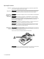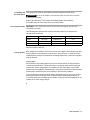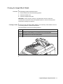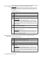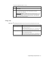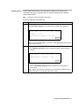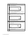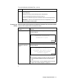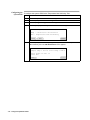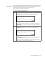
1
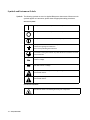
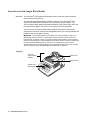
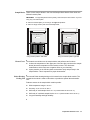
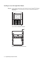
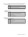
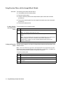
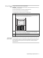
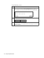
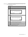
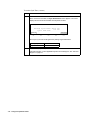
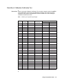
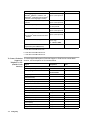
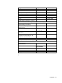
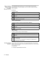
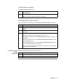
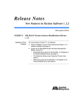
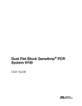
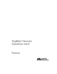
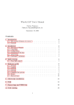
GeneAmp® PCR System 9700
Auto-Lid Dual 384 Sample Block Module
User’s Manual
© Copyright 2006, 2010 Applied Biosystems. All rights reserved.
Information in this document is subject to change without notice. Applied Biosystems assumes no responsibility for any errors that may appear in this
document.
APPLIED BIOSYSTEMS DISCLAIMS ALL WARRANTIES WITH RESPECT TO THIS DOCUMENT, EXPRESSED OR IMPLIED, INCLUDING
BUT NOT LIMITED TO THOSE OF MERCHANTABILITY OR FITNESS FOR A PARTICULAR PURPOSE. IN NO EVENT SHALL APPLIED
BIOSYSTEMS BE LIABLE, WHETHER IN CONTRACT, TORT, WARRANTY, OR UNDER ANY STATUTE OR ON ANY OTHER BASIS FOR
SPECIAL, INCIDENTAL, INDIRECT, PUNITIVE, MULTIPLE OR CONSEQUENTIAL DAMAGES IN CONNECTION WITH OR ARISING
FROM THIS DOCUMENT, INCLUDING BUT NOT LIMITED TO THE USE THEREOF.
NOTICE TO PURCHASER: LIMITED LICENSE
The combination of the GeneAmp® PCR System 9700 Sample Block Module with a GeneAmp® PCR System 9700 Base Unit is licensed under US
patents for thermal cycler apparatus and counterpart patent claims in other countries. No other rights are conveyed expressly, by implication, or by
estoppel. Further information on purchasing licenses may be obtained by contacting the Director of Licensing, Applied Biosystems, 850 Lincoln
Centre Drive, Foster City, California 94404, USA.
TRADEMARKS:
AB (Design), Applied Biosystems, and MicroAmp are registered trademarks, Applera, Celera Genomics, and BigDye is a trademark of
Applied Biosystems or its subsidiaries in the U.S. and/or certain other countries.
AmpErase, AmpliTaq, AmpliTaq Gold, EnviroAmp, GeneAmp, and TaqMan are registered trademarks of Roche Molecular Systems, Inc.
Microsoft, Windows, and Windows NT are trademarks of Microsoft Corporation.
All other trademarks are the sole property of their respective owners.
Part Number 4310838 Rev. D
06/2010
Contents
1 Safety Information
Overview . . . . . . . . . . . . . . . . . . . . . . . . . . . . . . . . . . . . . . . . . . . . . . . . . . . . . . . . . . . . . . . . . . 1-1
Symbols and Instrument Labels . . . . . . . . . . . . . . . . . . . . . . . . . . . . . . . . . . . . . . . . . . . . . . . . . 1-2
Operating Precautions . . . . . . . . . . . . . . . . . . . . . . . . . . . . . . . . . . . . . . . . . . . . . . . . . . . . . . . . 1-4
Safety . . . . . . . . . . . . . . . . . . . . . . . . . . . . . . . . . . . . . . . . . . . . . . . . . . . . . . . . . . . . . . . . . . . . . 1-8
2 Sample Block Module Overview
Overview . . . . . . . . . . . . . . . . . . . . . . . . . . . . . . . . . . . . . . . . . . . . . . . . . . . . . . . . . . . . . . . . . . 2-1
About the Auto-Lid Sample Block Module . . . . . . . . . . . . . . . . . . . . . . . . . . . . . . . . . . . . . . . . 2-2
Modules, Accessories, and Disposables. . . . . . . . . . . . . . . . . . . . . . . . . . . . . . . . . . . . . . . . . . . 2-4
3 Using/Maintaining the Sample Block Module
Overview . . . . . . . . . . . . . . . . . . . . . . . . . . . . . . . . . . . . . . . . . . . . . . . . . . . . . . . . . . . . . . . . . . 3-1
Installing the Auto-Lid Sample Block Module . . . . . . . . . . . . . . . . . . . . . . . . . . . . . . . . . . . . . 3-2
Using Reaction Plates with the Sample Block Module . . . . . . . . . . . . . . . . . . . . . . . . . . . . . . . 3-4
Cleaning the Sample Block Module. . . . . . . . . . . . . . . . . . . . . . . . . . . . . . . . . . . . . . . . . . . . . . 3-7
Fixing a Jam . . . . . . . . . . . . . . . . . . . . . . . . . . . . . . . . . . . . . . . . . . . . . . . . . . . . . . . . . . . . . . . . 3-9
4 Testing the Sample Block Module
Overview . . . . . . . . . . . . . . . . . . . . . . . . . . . . . . . . . . . . . . . . . . . . . . . . . . . . . . . . . . . . . . . . . . 4-1
Running the Calibration Verification Test . . . . . . . . . . . . . . . . . . . . . . . . . . . . . . . . . . . . . . . . . 4-2
Running the Temperature Non-Uniformity Test . . . . . . . . . . . . . . . . . . . . . . . . . . . . . . . . . . . . 4-8
Running System Performance Diagnostics . . . . . . . . . . . . . . . . . . . . . . . . . . . . . . . . . . . . . . . 4-15
Data Sheet: Calibration Verification Test . . . . . . . . . . . . . . . . . . . . . . . . . . . . . . . . . . . . . . . . . 4-19
Data Sheet: Temperature Non-Uniformity Test . . . . . . . . . . . . . . . . . . . . . . . . . . . . . . . . . . . . 4-20
A Getting Help
Overview . . . . . . . . . . . . . . . . . . . . . . . . . . . . . . . . . . . . . . . . . . . . . . . . . . . . . . . . . . . . . . . . . .A-1
Technical Support . . . . . . . . . . . . . . . . . . . . . . . . . . . . . . . . . . . . . . . . . . . . . . . . . . . . . . . . . . . .A-2
Index
i
Safety Information
1
Overview
About This Chapter This chapter provides information to help you safely operate the GeneAmp® PCR
System 9700 and the Auto-Lid Sample Block Module.
IMPORTANT Read this chapter before you install the system 9700 and the Auto-Lid Sample
Block Module.
In This Chapter The following topics are covered in this chapter:
Topic
Symbols and Instrument Labels
See Page
1-2
Operating Precautions
1-4
Safety
1-8
Safety Information 1-1
Symbols and Instrument Labels
Symbols The following symbols are used on Applied Biosystems instruments. Whenever such
symbols appear on instruments, please observe appropriate safety procedures.
Electrical Symbols
This symbol indicates the on position of the main power switch.
This symbol indicates the off position of the main power switch.
This symbol indicates the on/off position of a push-push main power switch.
This symbol indicates that a terminal may be connected to another
instrument’s signal ground reference.
This is not a protected ground terminal.
This symbol indicates that this is a protected ground terminal that must be
connected to earth ground before any other electrical connections are made
to the instrument.
~
~
This symbol indicates that this terminal either receives or delivers alternating
current or voltage.
This symbol indicates that this terminal either receives or delivers alternating
and direct current or voltage.
This symbol indicates the presence of high voltage and warns the user to
proceed with caution.
This symbol alerts you to consult the manual for further information and to
proceed with caution.
Non-electrical Symbols
This symbol illustrates a heater hazard. Proceed with caution when working
around these areas to avoid being burned by hot components.
1-2 Safety Information
Instrument Labels The following instrument labels are on the system 9700 with the Auto-Lid Sample
Block Module installed.
! WARNING Disconnect supply cord before opening. Grounding circuit
continuity is vital for safe operation of equipment. Never operate equipment
with grounding conductor disconnected.
AVERTISSEMENT: Debrancher le cordon d’alimentation avant d’ouvrir la
continuite des masses est essentielle.
Pour un fonctionnement sans danger. Ne jamais utiliser l’equipment si le fil
de terre n’est pas raccorde.
\
! WARNING HOT SURFACE. Use care when working around this area to
avoid being burned by hot components.
Attention. Surface chaude.
Safety Information 1-3
Operating Precautions
Overview The following precautions should be taken whenever you operate the system 9700
with the Auto-Lid Sample Block Module installed.
General Use
! CAUTION The instrument should be used according to the instructions provided in this
manual. If used otherwise, the protection provided by this instrument may be impaired.
Environment, ! CAUTION This instrument is designed for indoor use and for altitudes not exceeding 2000
Humidity, and meters.
Temperature ! CAUTION Do not operate in a Cold Room or a refrigerated area. The system 9700 will
operate safely when the ambient temperature is 5 °C to 40 °C (41 °F to 104 °F). The system
9700 will meet performance specifications when the ambient temperature is 15 °C to 30 °C and
the ambient relative humidity is 20 to 80%. These specifications have been calculated for
altitudes between 0 and 2000 meters.
! CAUTION This instrument is not designed for operation in an explosive environment. Do
not place the instrument close to potentially explosive materials or objects.
! CAUTION This instrument is not designed for operation with the heated cover retracted
when running at 4 °C. If the heated cover is retracted and the instrument runs at 4 °C, water
condensation may be excessive in the sample block area.
Sample Block ! WARNING PHYSICAL INJURY HAZARD. To protect yourself against burns, do not open the
Module heated cover or touch the sample block module when the word Hot displays on the screen. This
indicates a sample block temperature above 50 °C.
The hot areas for the Auto-Lid Sample Block Module are shown below.
STOP
F1
F2
F4
2
5
ENTE
R
GR1759
F3
1
4
7
3
8
F5
6
0
9
POWE
R
CE
! CAUTION To protect your samples and to guarantee the best temperature uniformity, keep
the heated cover closed at all times, except when loading or unloading samples.
1-4 Safety Information
Grounding and The system 9700 must be grounded for protection against electrical shock.
Electrical Safety ! WARNING Do not use an adapter to a two-terminal outlet, since this does not provide
positive ground protection.
Refer to the GeneAmp® PCR System 9700 Base Module User’s Manual
(P/N 0993-6247) for more information on electrical safety.
Power Requirements IMPORTANT You must be able to disconnect the main power supply to the instrument
immediately if necessary.
The following table specifies the electrical operating range for the instrument in
various parts of the world:
Location
Voltage (VAC)
Frequency
Amperage (A) Nominal
Japan
100 ±10%
50/60 Hz ±1%
3.16
USA/Canada
120 ±10%
50/60 Hz ±1%
4.20
EC
230 ±10%
50/60 Hz ±1%
3.14
Maximum power is 860 VA.
Voltage Quality Line voltage must be within ±10% of the nominal value. High or low voltages may have
adverse effects on the electronic components of the instrument. In areas where the
supplied power is subject to fluctuations exceeding these limits, a power line regulator
may be required.
Voltage Spikes
Short-duration, high-voltage spikes often cause random failures in microprocessor
controlled instrumentation. These spikes can be caused by other devices using the
same power source (refrigerators, air conditioners, and centrifuges) or by outside
influences such as lightning. A dedicated line and ground between the instrument and
building main electrical service are necessary to prevent such problems.
If your environment contains devices that are electrically noisy or you are in an area
with frequent electrical storms, a line conditioner with a recommended capacity of
2.0 VA will enhance the reliability of your system. This may be lower depending on the
conditioner or power supply design.
Safety Information 1-5
Physical Weight
Specifications
Sample Block Module
10 kg (22 lb)
Base Module
8.6 kg (19 lb)
Dimensions (footprint with sample block installed):
Height
26.0 cm (10 in.)
Width
28.0 cm (11 in.)
Depth
46.5 cm (19.5 in.)
Lifting the The combined weight of the base module and sample block module exceed 18 kg
Instrument (41 lb). Lifting or moving the assembled unit should be done with caution.
When lifting or moving a heavy object:
Step
Action
1
Assess the load and pathway of the lift and carry.
2
Ensure that the instrument can be gripped comfortably and securely.
3
Bring the load as close to the body as possible.
4
Keep the head and shoulders up and the upper body erect as the lift begins.
5
Lift with the legs by bending and straightening the knees.
! CAUTION If a direction change is necessary, don't twist and lift. Instead, move
the feet (pivot) .
6
Don't jerk. Lift and move smoothly and slowly.
7
If two or more individuals are involved in the lift, communicate your moves and
intentions.
8
Set the object down smoothly, again using your legs to support the weight. Make
sure fingers and other appendages are free of the object’s weight as it is put down.
0
Pollution Category The installation category (overvoltage category) for this instrument is II, and it is
classified as portable equipment. The instrument has a pollution degree rating of 2,
and may be installed in an environment that has nonconductive pollutants only.
Instrument Storage The system 9700 must be stored at a temperature between –20 °C and 60 °C
(–4 °F and 140 °F) at altitudes ranging from 0–12,000 meters above sea level.
IMPORTANT The system 9700 is guaranteed to meet performance specifications only when
the ambient temperature is 15–30 °C and the ambient relative humidity is 20–80% (between
altitudes of 0 and 2000 meters).
1-6 Safety Information
Communautes
Europeennes (CE)
Compliance
\
For our European customers, any product marked with the CE label meets
the European EMC directive 89/336/EEC and the Low Voltage Directive
72/23/EEC. This product meets Class A emission limits.
Routine Before using any cleaning or decontamination method except those recommended in
Maintenance for the manual, the user should check with Applied Biosystems to ensure that the
Safe Operation proposed method will not damage the equipment.
Maintain your instrument in good working order. In the event that the instrument has
been subjected to adverse environmental conditions (such as fire, flood, earthquake,
etc.), a service inspection of the instrument should be made to ensure safe operation.
Safety Information 1-7
Safety
Documentation User Five user attention words appear in the text of all Applied Biosystems user
Attention Words documentation. Each word implies a particular level of observation or action as
described below.
Note
Calls attention to useful information.
IMPORTANT Indicates information that is necessary for proper instrument operation.
! CAUTION Cautions the user that a potentially hazardous situation could occur, causing
injury to the user or damage to the instrument if this information is ignored.
! WARNING Warns the user that serious physical injury or death to the user or other
persons could result if these precautions are not taken.
! DANGER Indicates an imminently hazardous situation that if not avoided will result in
death or serious injury.
Chemical Hazard ! WARNING CHEMICAL HAZARD. Some of the chemicals used with Applied Biosystems
Warning instruments and protocols are potentially hazardous and can cause injury, illness, or death.
♦
Read and understand the material safety data sheets (MSDSs) provided by the
chemical manufacturer before you store, handle, or work with any chemicals or
hazardous materials.
♦
Minimize contact with chemicals. Wear appropriate personal protective equipment
when handling chemicals (e.g., safety glasses, gloves, or protective clothing). For
additional safety guidelines, consult the MSDS.
♦
Minimize the inhalation of chemicals. Do not leave chemical containers open. Use
only with adequate ventilation (e.g., fume hood). For additional safety guidelines,
consult the MSDS.
♦
Check regularly for chemical leaks or spills. If a leak or spill occurs, follow the
manufacturer’s cleanup procedures as recommended on the MSDS.
♦
Comply with all local, state/provincial, or national laws and regulations related to
chemical storage, handling, and disposal.
\
Chemical Waste ! WARNING CHEMICAL WASTE HAZARD. Wastes produced by Applied Biosystems
Hazard Warning instruments are potentially hazardous and can cause injury, illness, or death.
1-8 Safety Information
♦
Read and understand the material safety data sheets (MSDSs) provided by the
manufacturers of the chemicals in the waste container before you store, handle, or
dispose of chemical waste.
♦
Handle chemical wastes in a fume hood.
♦
Minimize contact with chemicals. Wear appropriate personal protective equipment
when handling chemicals (e.g., safety glasses, gloves, or protective clothing). For
additional safety guidelines, consult the MSDS.
♦
Minimize the inhalation of chemicals. Do not leave chemical containers open. Use
only with adequate ventilation (e.g., fume hood). For additional safety guidelines,
consult the MSDS.
♦
After emptying the waste container, seal it with the cap provided.
♦
Dispose of the contents of the waste tray and waste bottle in accordance with
good laboratory practices and local, state/provincial, or national environmental
and health regulations.
About MSDSs Some of the chemicals used with this instrument may be listed as hazardous by their
manufacturer. When hazards exist, warnings are prominently displayed on the labels
of all chemicals.
Chemical manufacturers supply a current MSDS before or with shipments of
hazardous chemicals to new customers and with the first shipment of a hazardous
chemical after an MSDS update. MSDSs provide you with the safety information you
need to store, handle, transport, and dispose of the chemicals safely.
We strongly recommend that you replace the appropriate MSDS in your files each
time you receive a new MSDS packaged with a hazardous chemical.
! WARNING CHEMICAL HAZARD. Be sure to familiarize yourself with the MSDSs
before using reagents or solvents.
Ordering MSDSs You can order free additional copies of MSDSs for chemicals manufactured or
distributed by Applied Biosystems using the contact information below.
To order documents by automated telephone service:
1
From the U.S. or Canada, dial 1.800.487.6809, or from outside the U.S. and Canada,
dial 1.858.712.0317.
2
Follow the voice instructions to order documents (for delivery by fax).
Note
There is a limit of five documents per fax request.
To order documents by telephone:
In the U.S.
Dial 1.800.345.5224, and press 1.
♦ To order in English, dial 1.800.668.6913 and press 1, then 2, then 1
In Canada
♦ To order in French, dial 1.800.668.6913 and press 2, then 2, then 1
From any other
country
See the specific region under “To Contact Technical Support by
Telephone or Fax (Outside North America)” .
To view, download, or order documents through the Applied Biosystems web site:
Step
Action
1
Go to http://www.appliedbiosystems.com
2
Click SERVICES & SUPPORT at the top of the page, click Documents on Demand,
then click MSDS.
3
Click MSDS Index, search through the list for the chemical of interest to you, then
click on the MSDS document number for that chemical to open a pdf of the MSDS.
For chemicals not manufactured or distributed by Applied Biosystems, call the
chemical manufacturer.
Safety Information 1-9
Instrument Safety Safety labels are located on the instrument. Each safety label has three parts:
Labels ♦ A signal word panel, which implies a particular level of observation or action (e.g.,
CAUTION or WARNING). If a safety label encompasses multiple hazards, the
signal word corresponding to the greatest hazard is used.
♦
A message panel, which explains the hazard and any user action required.
♦
A safety alert symbol, which indicates a potential personal safety hazard. See
“Symbols and Instrument Labels” on page 1-2 for an explanation of all the safety
alert symbols.
About Waste As the generator of potentially hazardous waste, it is your responsibility to perform the
Disposal actions listed below.
♦
Characterize (by analysis if necessary) the waste generated by the particular
applications, reagents, and substrates used in your laboratory.
♦
Ensure the health and safety of all personnel in your laboratory.
♦
Ensure that the instrument waste is stored, transferred, transported, and disposed
of according to all local, state/provincial, or national regulations.
Note Radioactive or biohazardous materials may require special handling, and disposal
limitations may apply.
Before Operating the Ensure that everyone involved with the operation of the instrument has:
Instrument ♦ Received instruction in general safety practices for laboratories
♦
Received instruction in specific safety practices for the instrument
♦
Read and understood all related MSDSs
! CAUTION Avoid using this instrument in a manner not specified by Applied Biosystems.
Although the instrument has been designed to protect the user, this protection can be impaired
if the instrument is used improperly.
1-10 Safety Information
Sample Block Module
Overview
2
Overview
About This Chapter This chapter provides an overview of the Auto-Lid Sample Block Module.
In This Chapter The following topics are covered in this chapter:
Topic
See Page
About the Auto-Lid Sample Block Module
2-2
Modules, Accessories, and Disposables
2-4
Sample Block Module Overview 2-1
About the Auto-Lid Sample Block Module
Overview The GeneAmp® PCR System 9700 amplifies nucleic acids using the polymerase
chain reaction (PCR) process.
The Auto-Lid Sample Block Module attaches to the top of the GeneAmp® PCR
System 9700 Base Module and allows you to perform up to 768 reactions. The
Auto-Lid Sample Block Module also adds automation to the system 9700, which can
help increase throughput. See “Auto-Lid” on page 2-4 for more information.
You can remove the Auto-Lid Sample Block Module and replace it with another
sample block module as needed. Interchangeability allows you to change sample well
formats as well as throughput capacity.
IMPORTANT Interchanging sample block modules may require a firmware change. If the
sample block module is placed on a base module running an earlier software version, the
instrument will not operate correctly. To upgrade the base module software, use the PCMCIA
(Personal Computer Memory Card International Association) interface card that is shipped with
the Auto-Lid Sample Block Module. For instructions on upgrading the software, see the
GeneAmp PCR System 9700 Base Module User’s Manual (P/N 0993-6247) or see “To Reach
Technical Support Through the Applied Biosystems Web Site” on page A-6.
Diagram
Auto-Lid
Sample Block
Module
Heated cover
Sample blocks
STOP
F1
F2
F3
1
4
ENTE
5
3
8
R
F5
6
0
9
CE
2-2 Sample Block Module Overview
F4
2
7
GR1759
System 9700
Base Module
POWE
R
Sample Blocks There are two sample blocks in the Auto-Lid Sample Block Module. Each holds one
384-well reaction plate.
IMPORTANT The right sample block is the primary control block, the left is a slave. If you are
using only one reaction plate:
♦ Place the reaction plate you are using in the right sample block.
♦ Place an empty reaction plate in the left sample block.
CAUTION - MOVING PART
CAUTION - MOVING PART
B
A
D
C
F
E
H
G
J
I
L
K
N
M
P
O
GR1761
9 10 11 12 13 14 15 16 17 18 19 20 21 22 23 24
9 10 11 12 13 14 15 16 17 18 19 20 21 22 23 24
8
9 10 11 12 13 14 15 16 17 18 19 20 21 22 23 24
8
7
8
7
6
7
6
5
6
5
4
5
4
3
4
3
2
3
2
1
2
1
1
GR1760
B
A
D
C
F
E
H
G
J
I
L
K
N
M
P
O
B
A
D
C
F
E
H
G
J
I
L
K
N
M
P
O
Using reaction plates in both sides
Using one reaction plate in right side
Heated Cover The heated cover slides over the sample blocks and performs two functions:
♦
It raises the temperature of the upper part of the tube (the part above the sample
blocks) above the temperature of the reaction mixture. This eliminates
condensation, which may have a negative effect on your chemistry.
♦
It puts pressure on the reaction plates to seat them firmly and precisely in the
sample blocks. This is important for proper heat transfer.
Peltier Heating/ The internal Peltier heating/cooling unit is housed in the sample block module. The
Cooling Unit sample block module is made of aluminum to provide the optimal thermal transfer
rate.
Platinum sensors in the sample block module provide:
♦
Wide temperature range: 4–99.9 °C
♦
Accuracy: ±0.25 °C from 35–100 °C
♦
Uniformity of each sample block: ±0.5 °C (measured after 30 sec at 95 °C)
♦
Uniformity of combined sample blocks: ±0.75 °C (measured after 30 sec at 95 °C)
♦
Long-term stability and high reliability
Sample Block Module Overview 2-3
Auto-Lid The auto-lid automatically closes the heated cover over the reaction plates at the start
of a PCR run and then opens the heated cover when the run is completed.
If you have access to an automatic arm, the auto-lid can also be programmed to:
♦
Place the reaction plates on the sample block
♦
Remove the reaction plates from the sample block
If you do not have access to an automatic tick arm, the reaction plates can be placed
and removed manually.
Modules, Accessories, and Disposables
Overview The modules listed below are available for the GeneAmp PCR System 9700 Base
Module. The accessories and disposables are for use with the Auto-Lid Sample Block
Module.
Ordering Order modules, accessories, and disposables from Applied Biosystems by part
number. See the tables below.
Modules
Part Number
96-Well Sample Block Module
N805-0251
96-Well Gold Sample Block Module
4314443
96-Well Aluminum Sample Block Module
4314445
Dual 384-Well Sample Block Module
N805-0400
Auto-Lid Dual 384 Sample Block Module
4312904
0.5-mL 60-Well Sample Block Module
4309131
Accessories
Part Number
Tool, 384-Well Plate Extraction
T-6273
Dual 384-Well Sample Block Module Temperature Verification Kit
4308354
Note
This kit is also used for the Auto-Lid Sample Block Module.
Disposables
Part Number
MicroAmp®
384-Well Reaction Plates (Box of 50)
4305505
MicroAmp®
Clear Adhesive Films (Pack of 100)
4306311
2-4 Sample Block Module Overview
Using/Maintaining the
Sample Block Module 3
Overview
About This Chapter This chapter describes how to use and maintain the Auto-Lid Sample Block Module.
In This Chapter The following topics are covered in this chapter:
Topic
See Page
Installing the Auto-Lid Sample Block Module
3-2
Using Reaction Plates with the Sample Block Module
3-4
Cleaning the Sample Block Module
3-7
Fixing a Jam
3-9
Using/Maintaining the Sample Block Module 3-1
Installing the Auto-Lid Sample Block Module
Diagrams A lever behind the sample block module releases it from the GeneAmp® PCR System
9700 Base Module. The top and bottom of the Auto-Lid Sample Block Module are
shown below.
CAUTION - MOVING PART
1
1
2
2
3
3
4
4
5
5
6
6
7
7
8
8
9 10 11 12 13 14 15 16 17 18 19 20 21 22 23 24
9 10 11 12 13 14 15 16 17 18 19 20 21 22 23 24
GR1760
A
C
B
E
D
G
F
I
H
K
J
M
L
O
N
P
B
A
D
C
E
G
F
I
H
K
J
M
L
O
N
P
Top view, Auto-Lid Sample Block Module
GR1762
Lever
Bottom view, Auto-Lid Sample Block Module
3-2 Using/Maintaining the Sample Block Module
Installing the Sample To install the sample block module into the GeneAmp PCR System 9700 Base
Block Module Module:
Step
Action
1
Pull the lever out from the sample block module.
2
Place the sample block module onto the base module, then push the sample
block module back to seat the electrical connections.
3
Push the lever into the base module to secure the sample block module.
Note
If the sample block module is not seated correctly, the instrument cannot be turned on.
Installing the To install the communication card and cable into the GeneAmp PCR System 9700
Communication Base Module:
Card and Cable
Step
Action
1
Insert the communication card into the slot at the rear of the right side of the
instrument (the label on the card face should be facing you).
2
Insert the connector end of the communication cable (very short cable) into the
communication card.
3
Insert the other end of the cable (plug type) into the receptacle on the sample
block module labeled I/O Port.
Installing the Power To install the power line cords into the sample block module and the GeneAmp PCR
Line Cords and System 9700 Base Module:
Powering Up
Step
Action
1
Plug one end of the power line cord into the sample block module receptacle and
the other end into an outlet.
2
Plug the very short jumper cable into the sample block module and the other into
the base module.
3
Flip the power switch located on the sample block module near the plug
receptacle and press the power button located on the front of the instrument.
Using/Maintaining the Sample Block Module 3-3
Using Reaction Plates with the Sample Block Module
Overview The following procedures describe how to:
♦
Load samples into the reaction plates
♦
Seal the reaction plates
♦
Place the reaction plates into the sample blocks (both manual and automatic
procedures)
♦
Remove the reaction plates from the sample blocks (both manual and automatic
procedures)
♦
Remove the adhesive films
Loading Samples To load samples into the reaction plates:
into the Reaction
Step
Action
Plates
1
Pipette the samples into the reaction plate wells.
Note
2
The sample volume range is 5–20 µL.
Seal the reaction plates with adhesive films. See “Sealing the Reaction Plates”
below.
Note Do not use mineral oil or glycerine in the sample blocks or as a vapor barrier
over the samples in the wells. The adhesive films prevent evaporation or
contamination. In addition, the Auto-Lid Sample Block Module’s heated cover
prevents condensation.
Sealing the Reaction Seal the reaction plates for the Auto-Lid Sample Block Module with MicroAmp® Clear
Plates Adhesive Films.
Note Do not use mineral oil or glycerine in the sample blocks or as a vapor barrier over the
samples in the wells. The adhesive films prevent evaporation or contamination. In addition, the
Auto-Lid Sample Block Module’s heated cover prevents condensation.
To seal the reaction plate:
Step
Action
1
Remove the paper backing from the adhesive film.
2
Place the adhesive side of the film onto the reaction plate.
3
Smooth down the adhesive film, working from the center of the reaction plate toward
the edges.
4
After the reaction plates have been sealed, place them into the sample blocks.
3-4 Using/Maintaining the Sample Block Module
Placing the Reaction Placing the Reaction Plates Into the Sample Blocks
Plates IMPORTANT The right sample block is the primary control block and the left is a slave. If you
are using only one reaction plate:
♦ Place the reaction plate you are using in the right sample block.
♦ Place an empty reaction plate in the left sample block.
To manually place the reaction plates in the sample blocks:
Step
1
Action
Place a 384-well reaction plate into the right sample block. Make sure the well
numbered A1 points toward the upper right corner of the sample block module, as
shown below. This orients the reaction plate for proper fit.
CAUTION - MOVING PART
A
C
B
E
D
G
F
H
J
I
L
K
N
M
P
O
1
2
3
4
5
6
7
9 10 11 12 13 14 15 16 17 18 19 20 21 22 23 24
GR1761
8
2
If you are using a second reaction plate, place it in the left sample block. Make sure
the well numbered A1 points toward the upper right corner of the sample block
module. This orients the reaction plate for proper fit.
3
Press the red button located near the right sample block to close the heated cover.
4
Process the samples as usual.
Removing the The 384-well plates can be removed by hand or with the assistance of the robotic arm.
Reaction Plates
The Plate Ejection system is a unique feature that allows for easy access by a robot
arm to remove each 384-well plate from the sample block, following cycling and
opening of the lid.
Using/Maintaining the Sample Block Module 3-5
Removing the To remove adhesive film:
Adhesive Film
Step
1
Action
Hold one corner of the adhesive film and pull it back across the reaction plate.
IMPORTANT Hold the reaction plate firmly down while pulling back the adhesive
film. This will help keep sample at the bottom of the wells. If the reaction plate is
tilted or jostled, the sample may have to be centrifuged.
3-6 Using/Maintaining the Sample Block Module
Cleaning the Sample Block Module
Overview The following procedures describe how to:
♦
Put the heated cover into the cleaning position
♦
Clean the heated cover
♦
Clean the sample block wells
IMPORTANT Before using any cleaning or decontamination method, except those
recommended in this manual, check with Applied Biosystems to ensure that the proposed
method will not damage the equipment.
Cleaning Position To clean the Auto-Lid Sample Block Module, you must first put the heated cover into
the cleaning position. Follow the steps below.
To put the heated cover into the cleaning position:
Step
Action
1
Make sure the heated cover is in the rear position. If it is not, press and release the
red button to automatically move the heated cover to the rear position.
2
The heated cover is now in the correct position.
3
Lift the front of the heated cover. The cleaning position is shown below.
Using/Maintaining the Sample Block Module 3-7
Cleaning the Heated Clean the heated cover once a month, or more frequently if needed.
Cover ! WARNING During instrument operation, the temperature of the heated cover can be as
high as 108 °C, and the temperature of the sample block module can be as high as 100 °C.
Before performing this procedure, wait until the heated cover and sample block module reach
room temperature.
To clean the heated cover:
Step
Action
1
Put the heated cover into the cleaning position. See “Cleaning Position” on
page 3-7.
2
Turn off the instrument.
3
Wait 20–30 minutes for the heated cover to cool down.
4
Soak a cotton swab or clean cloth with pure isopropanol and gently wipe the bottom
of the heated cover.
! WARNING CHEMICAL HAZARD. Isopropanol is a flammable liquid and
vapor. It may cause eye, skin, and upper respiratory tract irritation. Prolonged or
repeated contact may dry skin and cause irritation. It may cause central nervous
system effects such as drowsiness, dizziness, and headache, etc. Please read the
MSDS, and follow the handling instructions. Wear appropriate protective eyewear,
clothing, and gloves.
5
Remove any remaining isopropanol from the heated cover with a clean cloth and
return the cover to its normal position.
6
If the heated cover becomes contaminated with amplified DNA:
a. Wipe the heated cover with a clean cloth or cotton swab soaked in 10% bleach.
b. Wipe with a clean, damp cloth.
! WARNING CHEMICAL HAZARD. Sodium hypochlorite (bleach) is a liquid
disinfectant that can be corrosive to the skin and can cause skin depigmentation.
Please read the MSDS, and follow the handling instructions. Wear appropriate
protective eyewear, clothing, and gloves.
Cleaning the Sample Clean the sample block wells once a month, or more frequently if needed.
Block Wells
To clean the sample block wells:
Step
Action
1
Let the system 9700 cool to the idle setpoint (25°C).
2
Put the heated cover into the cleaning position. See “Cleaning Position” on
page 3-7.
3
Turn off the instrument.
4
Remove the reaction plates from the sample block module and set them aside.
5
Soak a cotton swab in pure isopropanol and clean the sample block wells
thoroughly.
! WARNING CHEMICAL HAZARD. Isopropanol is a flammable liquid and
vapor. It may cause eye, skin, and upper respiratory tract irritation. Prolonged or
repeated contact may dry skin and cause irritation. It may cause central nervous
system effects such as drowsiness, dizziness, and headache, etc. Please read the
MSDS, and follow the handling instructions. Wear appropriate protective eyewear,
clothing, and gloves.
3-8 Using/Maintaining the Sample Block Module
To clean the sample block wells:
Step
(continued)
Action
6
Remove any remaining isopropanol from the heated cover before reloading the
reaction plates.
7
If the sample block wells become contaminated with amplified DNA:
a. Clean the wells thoroughly with a cotton swab soaked in 10% bleach.
b. Wipe with a clean, damp cloth.
! WARNING CHEMICAL HAZARD. Sodium hypochlorite (bleach) is a liquid
disinfectant that can be corrosive to the skin and can cause skin depigmentation.
Please read the MSDS, and follow the handling instructions. Wear appropriate
protective eyewear, clothing, and gloves.
Fixing a Jam
About Jams The following table describes how to fix a jam that is causing the auto-lid to stop:
If the auto-lid jams...
Then...
while closing,
the auto-lid will automatically retract to the open position.
♦ Find the jam and clear it.
♦ Press the red button and hold for 1 sec. The heated cover
returns to the open position and the instrument is reset.
while opening,
the auto-lid will stop moving and remain in place.
♦ Try to find the jam and clear it.
♦ Press the red button and hold for 1 sec. The heated cover
returns to the open position and the instrument is reset.
Using/Maintaining the Sample Block Module 3-9
Testing the Sample Block
Module
4
Overview
About This Chapter This chapter describes how to perform tests that verify that your Auto-Lid Sample
Block Module is functioning properly.
In This Chapter The following topics are covered in this chapter:
Topic
See Page
Running the Calibration Verification Test
4-2
Running the Temperature Non-Uniformity Test
4-8
Running System Performance Diagnostics
4-15
Data Sheet: Calibration Verification Test
4-19
Data Sheet: Temperature Non-Uniformity Test
4-20
Testing the Sample Block Module 4-1
Running the Calibration Verification Test
Overview Use this test to verify the temperature calibration of your GeneAmp® PCR System
9700 Auto-Lid Sample Block Module.
The Calibration Verification Test consists of several subprocedures, which must be
done in order:
Subprocedure
See Page
Setting Up the 20-µL Probe Assembly
4-3
Configuring the System 9700
4-4
Running the Test
4-5
Evaluating the Results
4-7
! WARNING PHYSICAL INJURY HAZARD. Hot Surface. Use care when working around
the heated cover and sample block to avoid being burned by hot components.
Equipment Required This test requires the Dual 384-Well Sample Block Module Temperature Verification
Kit (P/N 4308354).
Note
This kit is also used for the Auto-Lid Sample Block Module.
Your kit includes:
♦
Light mineral oil
♦
Two 384-Well Temperature Verification Plates
♦
20-µL Probe Assembly
♦
Digital thermometer with 9V battery installed
4-2 Testing the Sample Block Module
Setting Up the 20-µL To set up the 20-µL Probe Assembly:
Probe Assembly
Step
Action
1
Make sure the heated cover is in the rear position. If it is not, press and release the
red button to automatically move the heated cover to the rear position.
2
Place both 384-Well Temperature Verification Plates on the sample blocks.
The plate labeled L1–L6 is for the left sample block. The plate labeled R1–R6 is for
the right sample block. Position the plates so the angled corners face away from
you.
Note The plates are used as a guide to help you locate the probes within the
sample blocks.
3
Use the stick end of a cotton swab to coat well R3 with mineral oil.
Note
The wells are too small for the swab end.
4
Place the 20-µL Probe Assembly into well R3.
5
Thread the probe wire through the channels in the 384-Well Temperature
Verification Plate to prevent damage to the probe and lead wires.
6
Make sure the probe is connected to the digital thermometer.
7
Press and release the red button to automatically close the heated cover.
IMPORTANT Seat the probe properly. If the probe wire is crushed when the
heated cover closes, the probe may be damaged.
8
Turn on the digital thermometer.
Note Refer to the instructions included with your Temperature Verification Kit for
a detailed description on operating the digital thermometer.
Testing the Sample Block Module 4-3
Configuring the To configure the system 9700 for the Calibration Verification Test:
System 9700
Step
Action
1
Turn on the system 9700. The main menu appears.
2
Press F4 (Util). The Utilities screen appears.
3
Press F1 (Diag). The Diagnostics screen appears.
4
Press F3 (TmpVer). The Temperature Verification screen appears.
Temperature Verification
Temp - Calibration Verification
TNU - Temperature Non-Uniformity
5
Temp
TNU
F1
F2
Exit
F3
F4
F5
Press F1 (Temp) to automatically configure the system 9700 for the Calibration
Verification Test. The Calibration Verification screen appears.
Calibration Verification
Block temp = xx.x°C Cover temp = xxx°C
Place probe in well R3
Press Run
Run
F1
4-4 Testing the Sample Block Module
Cancel
F2
F3
F4
F5
Running the Test Use the digital thermometer to take temperature readings of the sample well
connected to the 20-µL Probe Assembly. You will take a reading at two different
setpoint temperatures.
Note
If necessary, press F5 (Cancel) to exit the test.
To run the Calibration Verification Test:
Step
1
Action
Press F1 (Run). This starts the Calibration Verification Test.
The Calibration Verification screen appears with a setpoint value displayed.
Calibration Verification
Block temp = xx.x°C Cover temp = xxx°C
Setpoint is 85°C
Cover must be within 1°C of 105°C
Cancel
F1
F2
F3
F4
F5
Note The cover must be within 1 °C of 105 °C. It may take several minutes for the
system 9700 to ramp up.
2
During calibration:
a. The Calibration Verification screen counts down the time until the setpoint is
reached.
Calibration Verification
Block temp = xx.x°C Cover temp = xxx°C
Stabilizing at setpoint... x:xx
Cancel
F1
F2
F3
F4
F5
b. When the Stabilizing at setpoint value decrements to 0, read the digital
thermometer.
Note Refer to the instructions included with your Temperature Verification Kit for a
detailed description on operating the digital thermometer.
Testing the Sample Block Module 4-5
To run the Calibration Verification Test:
Step
3
(continued)
Action
Using the numeric keys, type the value displayed on the digital thermometer in the
Enter actual block temperature field.
Calibration Verification
Block temp = xx.x°C Cover temp = xxx°C
Enter actual block temperature xx.x
Cancel
F1
F2
F3
F4
F5
Note The digital thermometer displays a four-digit value; round this off to three
digits before typing it in the Calibration Verification screen.
Note To keep a permanent record of the test, record this value on the Calibration
Verification Test Data Sheet (page 4-19).
4
Press Enter. The system 9700 automatically begins the second reading (45 °C
setpoint). The Calibration Verification screen appears with the setpoint value
displayed.
Calibration Verification
Block temp = xx.x°C Cover temp = xxx°C
Setpoint is 45°C
Cover must be within 1°C of 105°C
Cancel
F1
Note
F2
F3
F4
F5
The cover must be within 1 °C of 105 °C.
5
Repeat step 2 and step 3 for the second reading.
6
The system 9700 evaluates the calibration of the sample block temperature for the
setpoint values you entered and displays the results. A summary screen appears at
the conclusion of the test.
Calibration Verification
Actual temperature at 85 °C
Actual temperature at 45 °C
xx.x
xx.x
Cancel
Accept
F1
F2
F3
F4
F5
If you entered values on the Calibration Verification Test Data Sheet, compare those
values with the actual test results.
7
4-6 Testing the Sample Block Module
Press F1 (Accept). To interpret the results, see “Evaluating the Results” on
page 4-7.
To run the Calibration Verification Test:
Step
8
(continued)
Action
When you have completed all measurements, be sure to:
♦ Press F5 (Exit).
♦ Remove the 20-µL Probe Assembly from the sample blocks.
♦ Turn off the digital thermometer and clean off the oil.
♦ Remove the 384-Well Temperature Verification Plates from the sample blocks.
IMPORTANT Make sure the sample blocks are at room temperature (~25 °C)
before removing the reaction plates.
Evaluating the When the system 9700 completes the Calibration Verification Test, one of two screens
Results appears. See the table below to evaluate the results.
If the sample block
module...
is properly calibrated,
Then the...
Calibration Verification screen appears with the following
message displayed:
Calibration Verification
Calibration is good
Exit
F1
does not pass the
Calibration Verification
Test,
F2
F3
F4
F5
Calibration Verification screen appears with the following
message displayed:
Calibration Verification
Instrument may require service.
Contact Applied Biosystems
Technical Support.
Exit
F1
F2
F3
F4
F5
♦ If the test fails, repeat the procedure to make sure the meter
was not misread and that errors were not made entering
data.
♦ If the test fails again, contact Applied Biosystems Technical
Support. See “Technical Support” on page A-2.
Testing the Sample Block Module 4-7
Running the Temperature Non-Uniformity Test
Overview Use this test to verify the temperature uniformity of the GeneAmp PCR System 9700
Auto-Lid Sample Block Module.
The Temperature Non-Uniformity Test consists of several subprocedures, which must
be done in order:
Subprocedure
See Page
Setting Up the 20-µL Probe Assembly
4-9
Configuring the System 9700
4-10
Running the Test
4-11
Evaluating the Results
4-14
! WARNING PHYSICAL INJURY HAZARD. Hot Surface. Use care when working around
the heated cover and sample block to avoid being burned by hot components.
Equipment Required This test requires the Dual 384-Well Sample Block Module Temperature Verification
Kit (P/N 4308354).
Note
This kit is also used for the Auto-Lid Sample Block Module.
Your kit includes:
♦
Light mineral oil
♦
Two 384-Well Temperature Verification Plates
♦
20-µL Probe Assembly
♦
Digital thermometer with 9V battery installed
4-8 Testing the Sample Block Module
Setting Up the 20-µL To set up the 20-µL Probe Assembly:
Probe Assembly
Step
Action
1
Make sure the heated cover is in the rear position. If it is not, press and release the
red button to automatically move the heated cover to the rear position.
2
Place both 384-Well Temperature Verification Plates on the sample blocks.
The plate labeled L1–L6 is for the left sample block. The plate labeled R1–R6 is for
the right sample block. Position the plates so the angled corners face away from
you.
Note The plates are used as a guide to help you locate the probes within the
sample blocks.
3
Use the stick end of a cotton swab to coat wells L1–L6 and R1–R6 with mineral oil.
Note
4
The wells are too small for the swab end.
Place the 20-µL Probe Assembly into well L1.
Note As the test progresses, you will move the 20-µL Probe Assembly to each of
the test wells (L1–L6 and R1–R6).
5
Thread the probe wire through the channels in the 384-Well Temperature
Verification Plate to prevent damage to the probe and lead wires.
6
Make sure the probe is connected to the digital thermometer.
7
Press and release the red button to automatically close the heated cover.
IMPORTANT Seat the probe properly. If the probe wire is crushed when the
heated cover closes, the probe may be damaged.
8
Turn on the digital thermometer.
Note Refer to the instructions included with your Temperature Verification Kit for a
detailed description on operating the digital thermometer.
Testing the Sample Block Module 4-9
Configuring the To configure the system 9700 for the Temperature Non-Uniformity Test:
System 9700
Step
Action
1
Turn on the system 9700. The main menu appears.
2
Press F4 (Util). The Utilities screen appears.
3
Press F1 (Diag). The Diagnostics screen appears.
4
Press F3 (TmpVer). The Temperature Verification screen appears.
Temperature Verification
Temp - Calibration Verification
TNU - Temperature Non-Uniformity
5
Temp
TNU
F1
F2
Exit
F3
F4
F5
Press F2 (TNU) to automatically configure the system 9700 for the Temperature
Non-Uniformity Test. The TNU Performance screen appears.
TNU Performance
Sample temp = xx.x°C Cover temp = xxx°C
Place Probe in well L1
Press Run
Run
F1
4-10 Testing the Sample Block Module
Cancel
F2
F3
F4
F5
Running the Test The Temperature Non-Uniformity Test uses the 20-µL Probe Assembly to test the
temperature uniformity of six different wells in each sample block.
Note
If necessary, press F5 (Cancel) to exit the test.
To run the Temperature Non-Uniformity Test:
Step
1
Action
Press F1 (Run). This starts the Temperature Non-Uniformity Test.
The TNU Performance screen appears with the setpoint value displayed.
TNU Performance
Sample temp = xx.x°C Cover temp = xxx°C
Setpoint is 94°C
Sample must be within 1.0°C of setpoint
Cancel
F1
F2
F3
F4
F5
Note The sample blocks must be within 1.0 °C of the setpoint. In addition, the
cover must be within 1 °C of 105 °C. It may take several minutes for the system
9700 to ramp up.
2
Take a temperature reading.
a. The TNU Performance screen counts down the time until the setpoint is
stabilized.
TNU Performance
Sample temp = xx.x°C Cover temp = xxx°C
Stabilizing at setpoint... x:xx
Cancel
F1
F2
F3
F4
F5
b. When the Stabilizing at setpoint value decrements to zero, read the digital
thermometer.
Note Refer to the instructions included with your Temperature Verification Kit for a
detailed description on operating the digital thermometer.
Testing the Sample Block Module 4-11
To run the Temperature Non-Uniformity Test:
Step
3
(continued)
Action
Using the numeric keys, type the value displayed on the digital thermometer in the
Enter actual block temperature field.
TNU Performance
Sample temp = xx.x°C Cover temp = xxx°C
Enter actual block temperature 00.0
Cancel
F1
F2
F3
F4
F5
Note The digital thermometer displays a four-digit value; round this off to three
digits before typing it in the TNU Performance screen.
Note To keep a permanent record of the test, record this value on the
Temperature Non-Uniformity Test Data Sheet (page 4-20).
4
Press Enter. The system 9700 automatically begins the second reading (37 °C
setpoint). The TNU Performance screen appears with the setpoint value displayed.
TNU Performance
Sample temp = xx.x°C Cover temp = xxx°C
Setpoint is 37°C
Sample must be within 1.0°C of setpoint
Cancel
F1
Note
F2
F3
F4
F5
The sample blocks must be within 1.0 °C of the setpoint.
5
Repeat step 2 and step 3 for the second reading.
6
Press Enter. The TNU Performance screen appears with the following prompt:
TNU Performance
Sample temp = xx.x°C Cover temp = xxx°C
Place probe in well xx
Press Run
Run
F1
4-12 Testing the Sample Block Module
Cancel
F2
F3
F4
F5
To run the Temperature Non-Uniformity Test:
Step
7
8
(continued)
Action
Press and release the red button to automatically open the heated cover. Repeat
step 4 through step 7 of “Setting Up the 20-µL Probe Assembly” on page 4-9 and
step 1 through step 6 of this procedure. Complete these steps for all 12 wells to be
tested:
Left Sample Block
Right Sample Block
L1
R1
L2
R2
L3
R3
L4
R4
L5
R5
L6
R6
The system 9700 evaluates the uniformity of the sample block temperature for the
setpoint values you entered and displays the results. A summary screen appears at
the conclusion of the test.
Well
L1
L2
L3
L4
Accept
F1
94 °C
xx.x
xx.x
xx.x
xx.x
37 °C
xx.x
xx.x
xx.x
xx.x
F2
Well
L5
L6
R1
R2
More
F3
94 °C
xx.x
xx.x
xx.x
xx.x
37 °C
xx.x
xx.x
xx.x
xx.x
Cancel
F4
F5
If you entered values on the Temperature Non-Uniformity Test Data Sheet, compare
those values with the actual test results.
9
Press F1 (Accept). To interpret the results, see “Evaluating the Results” on
page 4-14.
10
When you have completed all measurements, be sure to:
♦ Press F5 (Cancel).
♦ Remove the 20-µL Probe Assembly from the sample blocks.
♦ Turn off the digital thermometer and clean off the oil.
♦ Remove the 384-Well Temperature Verification Plates from the sample blocks.
IMPORTANT Make sure the sample blocks are at room temperature (~25 °C)
before removing the reaction plates.
Testing the Sample Block Module 4-13
Evaluating the When the system 9700 completes the Temperature Non-Uniformity Test, the TNU
Results Performance screen appears. See the table below to evaluate the results.
If the...
Then...
Temperature of the
sample block wells is
uniform,
Pass appears after each setpoint temperature.
TNU Performance
TNU at 94°C is xx.xx - Pass
TNU at 37°C is xx.xx - Pass
Cancel
F1
Temperature variation of
the sample block wells
exceeds performance
specifications,
F2
F3
F4
F5
Fail appears after the setpoint temperature(s) for which the test
failed.
TNU Performance
TNU at 94°C is xx.xx - Fail
TNU at 37°C is xx.xx - Fail
Cancel
F1
F2
F3
F4
F5
♦ If the test fails, repeat the procedure to make sure the meter
was not misread and that errors were not made entering
data.
♦ If the test fails again, contact Applied Biosystems Technical
Support. See “Technical Support” on page A-2.
4-14 Testing the Sample Block Module
Running System Performance Diagnostics
Overview After you have configured the GeneAmp PCR System 9700, conduct the System
Performance Diagnostics to verify the integrity of the cooling and heating system.
There are two System Performance Diagnostics:
♦
Rate Test
♦
Cycle Test
Equipment Required These diagnostics require:
♦
Two MicroAmp® 384-Well Reaction Plates
Running the Rate Use the Rate Test to verify that the Peltier units are operating correctly. The test takes
Test approximately 10 minutes to run.
To run the Rate Test:
Step
Action
1
Turn on the system 9700. The main menu appears.
2
Press F4 (Util). The Utilities screen appears.
3
Press F1 (Diag). The Diagnostics screen appears.
4
Press F2 (System). The System Performance screen appears.
System Performance
Rate - Cool and Heat Rate Test
Cycle - Cycle Performance Test
5
Rate
Cycle
F1
F2
Exit
F3
F4
F5
Press F1 (Rate) from the System Performance screen. A Warning message
appears.
WARNING!!!
Install the Appropriate Empty
Consumables into the Sample Block.
Refer to System Performance Section
of Block User Manual.
Cancel
Cont
F1
6
F2
F3
F4
F5
Note
You will install the MicroAmp 384-Well Reaction Plates.
Note
Make sure the reaction plates are sealed with the adhesive film.
Place empty MicroAmp 384-Well Reaction Plates in the sample blocks. Press and
release the red button to automatically close the heated cover.
7
After you have installed the reaction plates, press F1 (Cont). The instrument runs
through a series of tests in which the sample blocks are stabilized at 35 °C, 94 °C,
and 4 °C.
Testing the Sample Block Module 4-15
To run the Rate Test:
Step
8
(continued)
Action
View the test results.
At the conclusion of the test, the Cool and Heat Rate Test screen appears. The
screen displays the test results and indicates whether the test passed or failed.
Cool and Heat Rate Test
Pass
Heating rate: x.xx °C/s
Cooling rate: x.xx °C/s
Cancel
Print
F1
9
10
F2
F3
F4
F5
Check your Rate Test results against the passing ranges listed below.
Heating Rate
> 1.0 °C /second
Cooling Rate
> –1.4 °C /second
If the test fails, repeat the procedure once.
If the test fails again, contact Applied Biosystems Technical Support. See “Technical
Support” on page A-2.
4-16 Testing the Sample Block Module
Running the Cycle Use the Cycle Test to verify that the PCR cycling function operates properly. This test
Test takes approximately 15 minutes to run.
To run the Cycle Test:
Step
Action
1
Turn on the system 9700. The main menu appears.
2
Press F4 (Util). The Utilities screen appears.
3
Press F1 (Diag). The Diagnostics screen appears.
4
Press F2 (System). The System Performance screen appears.
System Performance
Rate - Cool and Heat Rate Test
Cycle - Cycle Performance Test
5
Rate
Cycle
F1
F2
Exit
F3
F4
F5
Press F2 (Cycle) from the System Performance screen. A Warning message
appears.
WARNING!!!
Install the Appropriate Empty
Consumables into the Sample Block.
Cancel
Cont
F1
Note
F2
F3
F4
F5
You will install the MicroAmp 384-Well Reaction Plates.
6
Place empty MicroAmp 384-Well Reaction Plates in the sample blocks. Press and
release the red button to automatically close the heated cover.
7
After you have installed the reaction plates, press F1 (Cont). The Cycle Test
executes a two-temperature PCR cycling protocol, then measures and reports the
average cycle time and the cycle-to-cycle variation.
IMPORTANT Pressing Pause during the Cycle Test may generate false test results. Rerun
the Cycle Test if Pause was pressed during the test.
Testing the Sample Block Module 4-17
To run the Cycle Test:
Step
8
(continued)
Action
View the test results.
At the conclusion of the test, the Cycle Performance screen appears. The screen
displays the test results and whether the test passed or failed.
Cycle Performance
Pass
Average Cycle Time: xxx.x sec
x.x sec
Cycle Time STD:
Print
F1
Cancel
F2
F3
F4
F5
Check your Cycle Test results against the passing ranges listed below.
9
Average Cycle Time
≤ 140 seconds
Cycle Time STD
< 5 seconds
If the test fails, repeat the procedure once.
If the test fails again, contact Applied Biosystems Technical Support. See “Technical
Support” on page A-2.
4-18 Testing the Sample Block Module
Data Sheet: Calibration Verification Test
Instructions When running the Calibration Verification Test, record the setpoint values for well R3
on this data sheet. At the end of the Calibration Verification Test, check the values
displayed on the system 9700 against the values recorded here. This will help you
maintain accurate test records.
Note
If desired, you may photocopy this page.
.
Date
Tested By Probe Serial No.
Thermometer
Serial No.
Setpoint Value: Well R3
85 °C
45 °C
Testing the Sample Block Module 4-19
Data Sheet: Temperature Non-Uniformity Test
Instructions When running the Temperature Non-Uniformity Test, record the setpoint values for
wells L1–L6 and R1–R6 on this data sheet. At the end of the Temperature
Non-Uniformity Test, check the values displayed on the system 9700 against the
values recorded here. This will help you maintain accurate test records.
Note
If desired, you may photocopy this page.
Date
Tested By
Probe Serial No.
Thermometer Serial No.
Setpoint Value
L1
L2
L3
L4
L5
L6
R1
R2
R3
R4
R5
R6
4-20 Testing the Sample Block Module
94 °C
37 °C
Getting Help
A
Overview
About this Appendix This appendix describes how to get technical help from Applied Biosystems.
Getting Help A-1
Technical Support
Contacting You can contact Applied Biosystems for technical support:
Technical Support ♦ By e-mail
♦
By telephone or fax
♦
Through the Applied Biosystems web site
You can order Applied Biosystems user documents, MSDSs, certificates of analysis,
and other related documents 24 hours a day. In addition, you can download
documents in PDF format from the Applied Biosystems web site. (Please see the
section “To Obtain Technical Documents” following the telephone information below)
To Contact Technical You can contact Applied Biosystems Technical Support by e-mail for help in the
Support by E-Mail following product areas:
Product/Product Area
E-mail address
Genetic Analysis (DNA Sequencing)
[email protected]
Sequence Detection Systems (Real-Time
PCR) and PCR
[email protected]
Protein Sequencing, Peptide, and DNA
Synthesis
[email protected]
♦ Biochromatography (BioCAD®,
SPRINT™, VISION™, and INTEGRAL®
Workstations and POROS® Perfusion
Chromatography Products)
[email protected]
♦ Expedite™ 8900 Nucleic Acid Synthesis
Systems
♦ MassGenotyping Solution 1™ (MGS1)
Systems
♦ PNA Custom and Synthesis
♦ Pioneer™ Peptide Synthesizers
♦ Proteomics Solution 1™ (PS1) Systems
♦ ICAT™ Reagent
♦ FMATä 8100 HTS Systems
♦ Marinerä ESI-TOF Mass Spectrometry
Workstations
♦ Voyagerä MALDI-TOF Biospectrometry
Workstations
♦ CytoFluor® 4000 Fluorescence Plate
Reader
A-2 Getting Help
LC/MS
(Applied Biosystems/MDS Sciex)
[email protected]
Chemiluminescence (Tropix)
[email protected]
To Contact Technical
Support by
Telephone or Fax
(North America)
To contact Applied Biosystems Technical Support in North America, use the telephone
or fax numbers in the table below.
Note To schedule a service call for other support needs, or in case of an emergency, dial
1.800.831.6844, then press 1.
Product/Product Area
Telephone
Fax
1.800.831.6844,
then press 8a
1.650.638.5981
DNA Synthesis
1.800.831.6844,
press 2, then press 1a
1.650.638.5981
Fluorescent DNA Sequencing
1.800.831.6844,
press 2, then press 2a
1.650.638.5981
Fluorescent Fragment Analysis
(including GeneScan® applications)
1.800.831.6844,
press 2, then press 3a
1.650.638.5981
Integrated Thermal Cyclers (ABI PRISM®
877 and Catalyst 800 instruments)
1.800.831.6844,
press 2, then press 4a
1.650.638.5981
ABI PRISM® 3100 Genetic Analyzer
1.800.831.6844,
press 2, then press 6a
1.650.638.5981
Peptide Synthesis
(433 and 43x Systems)
1.800.831.6844,
press 3, then press 1a
1.650.638.5981
Protein Sequencing
(Procise® Protein Sequencing Systems)
1.800.831.6844,
press 3, then press 2a
1.650.638.5981
Sequence Detection Systems
(Real-Time PCR) and PCR
1.800.762.4001,
then press:
1.240.453.4613
ABI
PRISM ®
3700 DNA Analyzer
1 for PCRa
2 for TaqMan®
applications and
Sequence Detection
Systems including ABI
Prism‚ 7700, 7900,
and 5700a
6 for the 6700
Automated Sample
Prep Systema
or
1.800.831.6844, then
press 5a
♦ Marinerä ESI-TOF Mass
Spectrometry Workstations
1.800.899.5858,
press 1, then press 3b
1.508.383.7855
♦ Voyagerä MALDI-TOF
Biospectrometry Workstations
♦ MassGenotyping Solution 1ä (MGS1)
Systems
♦ Proteomics Solution 1ä (PS1)
Systems
♦ ICATä Reagent
Getting Help A-3
Product/Product Area
Telephone
Fax
Biochromatography
(BioCAD®, SPRINT ä, VISIONä, and
INTEGRAL® Workstations and POROS®
Perfusion Chromatography Products)
1.800.899.5858,
press 1, then press 4b
1.508.383.7855
Expediteä 8900 Nucleic Acid Synthesis
Systems
1.800.899.5858,
press 1, then press 5b
1.508.383.7855
Pioneerä Peptide Synthesizers
1.800.899.5858, press
1, then press 5b
1.508.383.7855
PNA Custom and Synthesis
1.800.899.5858,
press 1, then press 5b
1.508.383.7855
♦ FMATä 8100 HTS Systems
1.800.899.5858,
press 1, then press 6b
1.508.383.7855
Chemiluminescence (Tropix)
1.800.542.2369
(U.S. only),
or 1.781.271.0045c
1.781.275.8581
LC/MS
(Applied Biosystems/MDS Sciex)
1.800.952.4716
1.508.383.7899
♦ CytoFluor® 4000 Fluorescence Plate
Reader
a. 5:30 AM to 5:00 PM Pacific time.
b. 8:00 AM to 6:00 PM Eastern time.
c. 9:00 AM to 5:00 PM Eastern time.
To Contact Technical To contact Applied Biosystems Technical Support or Field Service outside North
Support by America, use the telephone or fax numbers below.
Telephone or Fax
Telephone
Fax
(Outside North Region
Eastern Asia, China, Oceania
America)
Australia (Scoresby, Victoria)
61 3 9730 8600
61 3 9730 8799
China (Beijing)
86 10 64106608 or
86 800 8100497
86 10 64106617
Hong Kong
852 2756 6928
852 2756 6968
India (New Delhi)
91 11 653 3743/3744
91 11 653 3138
Korea (Seoul)
82 2 593 6470/6471
82 2 593 6472
Malaysia (Petaling Jaya)
60 3 79588268
60 3 79549043
Singapore
65 896 2168
65 896 2147
Taiwan (Taipei Hsien)
886 2 2358 2838
886 2 2358 2839
Thailand (Bangkok)
66 2 719 6405
66 2 319 9788
Europe
A-4 Getting Help
Austria (Wien)
43 (0)1 867 35 75 0
43 (0)1 867 35 75 11
Belgium
32 (0)2 532 4484
32 (0)2 582 1886
Denmark (Naerum)
45 45 58 60 00
45 45 58 60 01
Finland (Espoo)
358 (0)9 251 24 250
358 (0)9 251 24 243
France (Paris)
33 (0)1 69 59 85 85
33 (0)1 69 59 85 00
Germany (Weiterstadt)
49 (0)6150 101 0
49 (0)6150 101 101
Italy (Milano)
39 (0)39 83891
39 (0)39 838 9492
Region
Telephone
Fax
Norway (Oslo)
47 23 12 06 05
47 23 12 05 75
Portugal (Lisboa)
351.(0)22.605.33.14
351.(0)22.605.33.15
Spain (Tres Cantos)
34.(0)91.806.1210
34.(0)91.806.12.06
Sweden (Stockholm)
46 (0)8 619 4400
46 (0)8 619 4401
Switzerland (Rotkreuz)
41 (0)41 799 7777
41 (0)41 790 0676
The Netherlands (Nieuwerkerk a/d
IJssel)
31 (0)180 392400
31 (0)180 392409 or
31 (0)180 392499
United Kingdom (Warrington, Cheshire)
44 (0)1925 825650
44 (0)1925 282502
European Managed Territories (EMT)
Africa, English speaking
(Johannesburg, South Africa)
27 11 478 0411
27 11 478 0349
Africa, French speaking
(Paris, France)
33 1 69 59 85 11
33 1 69 59 85 00
India (New Delhi)
91 11 653 3743
91 11 653 3138
91 11 653 3744
Poland, Lithuania, Latvia, and Estonia
(Warszawa)
48 22 866 40 10
48 22 866 40 20
For all other EMT countries not listed
(Central and southeast Europe, CIS,
Middle East, and West Asia)
44 1925 282481
44 1925 282509
Japan
Japan (Hacchobori, Chuo-Ku, Tokyo)
81 3 5566 6230
81 3 5566 6507
Latin America
Caribbean countries, Mexico, and
Central America
52 55 35 3610
52 55 66 2308
Brazil
0 800 704 9004 or
55 11 5070 9654
55 11 5070 9694/95
Argentina
800 666 0096
55 11 5070 9694/95
Chile
1230 020 9102
55 11 5070 9694/95
Uruguay
0004 055 654
55 11 5070 9694/95
Getting Help A-5
To Reach Technical At the Applied Biosystems web site, you can search through frequently asked
Support Through questions (FAQs) or a solution database, or you can submit a question directly to
the Applied Technical Support.
Biosystems Web Site
Search FAQs
To search for FAQs:
Step
Action
1
Go to http://www.appliedbiosystems.com
2
Click SERVICES & SUPPORT at the top of the page, then click Frequently Asked
Questions.
3
Click you geographic region for the product area of interest.
4
Follow the instructions under the Frequently Asked Questions section (1) to display a
list of FAQs for your area of interest.
Search the Solution Database
To search for solutions to problems using the Solution Database:
Step
Action
1
Go to http://www.appliedbiosystems.com
2
Click SERVICES & SUPPORT at the top of the page, then click Frequently Asked
Questions.
3
Follow the instructions under the Search the Solution Database section (2) to find a
solution to your problem.
Submit a Question
To submit a question directly to Technical Support:
1
Go to http://www.appliedbiosystems.com
2
Click SERVICES & SUPPORT at the top of the page, then click Frequently Asked
Questions.
3
In the Personal Assistance – E-Mail Support section (3), click Ask Us RIGHT NOW.
4
In the displayed form, enter the requested information and your question, then click
Ask Us RIGHT NOW.
Within 24 to 48 hours, you will receive an e-mail reply to your question from an
Applied Biosystems technical expert.
To Obtain Technical You can obtain technical documents, such as Applied Biosystems user documents,
Documents MSDSs, certificates of analysis, and other related documents for free, 24 hours a day.
You can obtain documents:
A-6 Getting Help
♦
By telephone
♦
Through the Applied Biosystems web site
Ordering Documents by Telephone
To order documents by telephone:
1
From the U.S. or Canada, dial 1.800.487.6809, or from outside the U.S. and Canada,
dial 1.858.712.0317.
2
Follow the voice instructions to order documents (for delivery by fax).
Note
There is a limit of five documents per fax request.
Obtaining Documents Through the Web Site
To view, download, or order documents through the Applied Biosystems web site:
Step
Action
1
Go to http://www.appliedbiosystems.com
2
Click SERVICES & SUPPORT at the top of the page, then click Documents on
Demand.
3
In the search form, enter and select search criteria, then click Search at the bottom
of the page.
4
In the results screen, do any of the following:
♦ Click the pdf icon to view a PDF version of the document.
♦ Right-click the pdf icon, then select Save Target As to download a copy of the
PDF file.
♦ Select the Fax check box, then click Deliver Selected Documents Now to have the
document faxed to you.
♦ Select the Email check box, then click Deliver Selected Documents Now to have
the document (PDF format) e-mailed to you.
Note There is a limit of five documents per fax request, but no limit on the number
of documents per e-mail request.
To Obtain Customer To obtain Applied Biosystems training information:
Training
Step
Action
Information
1
Go to http://www.appliedbiosystems.com
2
Click SERVICES & SUPPORT at the top of the page, then click Training.
Getting Help A-7
Index
Numerics
20-µL Probe Assembly, setting up
Calibration Verification Test 4-3
Temperature Non-Uniformity Test
96-Well Sample Block Module
part number 2-4
E
electrical symbols 1-2
e-mail, address for technical support A-2
4-9
A
adhesive films
part number 2-4
removing 3-6
sealing the reactions plates with 3-4
C
Calibration Verification Test 4-2 to 4-7
20-µL Probe Assembly, setting up 4-3
data sheet 4-19
evaluating the results 4-7
required equipment 4-2
running the test 4-5, 4-7
cleaning the sample block module 3-7 to 3-9
Communautes Europeennes (CE) Compliance 1-7
cooling
information 2-3
verifying cooling system 4-15
customer support. See technical support A-2
Cycle Test, running 4-17 to 4-18
D
data sheets
Calibration Verification Test 4-19
Temperature Non-Uniformity Test 4-20
diagnostics 4-15 to 4-18
Cycle Test, running 4-17 to 4-18
Rate Test, running 4-15 to 4-16
diagrams, sample block module
attached to 9700 Base Module 2-2
cleaning position 3-7
top and bottom views 3-2
digital thermometer 4-3, 4-9
Calibration Verification Test 4-2
Temperature Non-Uniformity Test 4-8
DNA contamination
heated cover 3-8
sample block wells 3-9
Documents on Demand A-6
Dual 384-Well Sample Block Module
part number 2-4
Dual 384-Well Sample Block Module Temperature
Verification Kit
part number 2-4
F
Field Service in North America, contacting A-3
G
grounding and electrical safety 1-5
H
heated cover
about 2-3
cleaning 3-8
DNA contamination 3-8
heating and cooling, information 2-3
I
installing the sample block module 3-3
instrument labels 1-3
interchangeability
sample block modules 2-2
Internet address
customer training information A-7
Documents on Demand A-6
J
jams, fixing 3-9
L
loading samples 3-4
M
maintenance, routine 1-7
MicroAmp 384-Well Reaction Plates
part number 2-4
MicroAmp Clear Adhesive Films
part number 2-4
MSDSs 1-9
N
non-electrical symbols 1-2
O
operating precautions 1-4 to 1-7
ordering parts 2-4
P
parts, ordering
modules, accessories, and disposables 2-4
Index-1
PCR cycling function, testing 4-17 to 4-18
Peltier unit
heating/cooling unit 2-3
verifying running correctly 4-15
performance tests 4-15 to 4-18
Cycle Test, running 4-17 to 4-18
Rate Test, running 4-15 to 4-16
placing the reaction plates 3-5
pollution category 1-6
R
Rate Test, running 4-15 to 4-16
reaction plates
loading samples into 3-4
manually loading into the sample blocks 3-5
manually removing from the sample blocks 3-5
part number 2-4
removing adhesive films from 3-6
sealing 3-4
using with the sample block module 3-4, 3-6
S
safety 1-1 to 1-10
sample block modules
interchanging 2-2
sample blocks
about 2-3
cleaning the wells 3-8
DNA contamination in wells 3-9
manually loading reaction plates into 3-5
manually removing reaction plates from 3-5
verifying calibration 4-2 to 4-7
verifying temperature uniformity 4-8 to 4-14
samples, loading into the reaction plates 3-4
sealing the reaction plates 3-4
specifications, physical 1-6
storing instrument 1-6
symbols
Communautes Europeennes (CE) Compliance 1-7
electrical 1-2
non-electrical 1-2
system performance tests
Cycle Test, running 4-17 to 4-18
Rate Test, running 4-15 to 4-16
T
technical support A-2 to A-7
e-mail address A-2
Internet address A-6
regional sales offices A-4 to A-5
telephone/fax (North America) A-3, A-4
Temperature Non-Uniformity Test 4-8 to 4-14
data sheet 4-20
evaluating the results 4-14
required equipment 4-8
running the test 4-11 to 4-13
tests
Index-2
Calibration Verification Test 4-2 to 4-7
Cycle Test 4-17 to 4-18
Rate Test 4-15 to 4-16
Temperature Non-Uniformity Test 4-8 to 4-14
TmpVer soft key 4-4, 4-10
Tool, 384-Well Plate Extraction
part number 2-4
training
obtaining information A-7
V
voltage quality 1-5
Worldwide Sales and Support
Applied Biosystems vast distribution and
service network, composed of highly trained
support and applications personnel,
reaches 150 countries on six continents.
For sales office locations and technical support,
please call our local office or refer to our
Web site at www.appliedbiosystems.com.
Applied Biosystems is committed to
providing the world’s leading technology
and information for life scientists.
Headquarters
850 Lincoln Centre Drive
Foster City, CA 94404 USA
Phone: +1 650.638.5800
Toll Free (In North America): +1 800.345.5224
Fax: +1 650.638.5884
06/2010
www.appliedbiosystems.com
Part Number 4310838 Rev. D