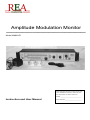
1
Amplitude Modulation Monitor
_______________
Model AMM-HF1
Enter the complete Model Number and
Serial Number which are located on the rear
of the Modulation Monitor cabinet. Retain
this information for future reference.
Model:____________________________
Instruction and User Manual
Serial Number:______________________
Thank You for purchasing the REA AMM-HF1 Modulation Monitor ! Before
use, please read this instruction manual, and in particular read the safety
information and precautions contained in the following pages to ensure safe
use of your new Modulation Monitor.
Important Use and Safety Information
Cautions:
1. To prevent fire or shock, do not expose this unit to rain, water or moisture.
2. Unit must be operated in a properly ventilated environment. The ambient
temperature must not exceed 80 degrees Fahrenheit.
3. Do not block the unit’s ventilation openings.
4. Do not place the unit on or above other equipment that generates heat.
5. This equipment must only be connected to the power supply / transformer that is
supplied. Use of any other power supply or transformer can result in a fire, shock
or other safety hazard, and will invalidate the unit’s warrantee.
6. Do not attempt to service or modify the power supply / transformer. The power
supply / transformer is designed to operate from a 120V AC, 60hZ source only.
7. Important: Do not expose the power supply / transformer to water or rain or
moisture. It the power supply / transformer is damaged in any way, do not use.
Refer servicing to qualified service personnel.
8. Do not exceed the power rating of the RF pickup unit. Exceeding the power
rating of the pickup can result in damage to the pickup unit and the modulation
monitor itself, excessive heat, and possible fire hazard.
9. Observe RF Safety Rules. This equipment is designed to be installed and used
by licensed and trained personnel who understand RF Safety, grounding and
other safety issues involving RF radiation, shielding, grounding, and lightening
protection.
10.The peak power rating of the RF pickup unit is 6.25 x the carrier power rating
(150% positive modulation). Do not exceed the peak power rating of the RF
pickup units.
Important Notice Regarding Product Use and Applications
This equipment is designed to provide a reasonable indication of modulation of
standard Amplitude Modulated equipment, and considerable efforts have been made
with respect to accuracy. However, this equipment has NOT been certified by the FCC
or any other agency as to its accuracy, and therefore this equipment cannot be used to
provide absolute indications or measurement of modulation as may be required by the
FCC or any other regulatory agency for proper or safe transmitter operation.
Page 1.
Note: This equipment is not intended for use where loss of life or property is a
possibility.
Changes in Product Appearance and Specifications
Radio Engineering Associates Inc. reserves the right to make changes in product
specifications, features and performance without notice. The pictures shown in this
manual and in advertising materials may differ somewhat from the actual product, due
to availability of parts and materials, and changes in manufacturing.
Technical Specifications
RF Frequency Range:
Standard R.E.A. Pickup Units: 1-30mHz
Other RF Pickup units are available
Number of Inputs for Pickup Units:
5
Input Connector from RF Pickup, on Monitor: (5) 1/8 inch stereo mini phone jack
RF Pickup Unit RF Input Connector Type:
SO239, High Impedance
RF Pickup Unit Output Connector:
1/8 inch stereo mini phone jack
Demodulated Carrier DC Input Voltage:
4V to 12V max (surge protected)
Measurement Accuracy:
Modulation Meter Range – Positive:
Modulation Meter Range – Negative:
Negative Peak Flasher Adjustment Range:
+/- 2.5% at 100% Modulation
0 – 150%
0 – 100%
85 – 100%
Audio Outputs:
2; 1/4 inch stereo phone on front
1/8 inch stereo mini phone on back
Maximum Audio Output Voltage:
Headphone Jack Impedance:
Demodulated Audio Frequency Response:
6V Peak to Peak, 100% modulation
20 Ohms
20 – 20,000 Hz +/- 1.5dB @ 95% Mod.
Power Requirements:
Power Supply Specifications:
120VAC 50 / 60 Hz, 10 W
16VAC 1 Amp UL listed wall transformer
Cabinet Size (without rack ears attached):
Mounting Options:
Operating Environmental Temp Range:
17w x 3.5h x 4.5d (2 RU in height)
19 inch rack mount or tabletop
33 deg. F. to 95 deg. F.
Page 2.
Contents
Important Use and Safety Information __________________________ 1
Cautions:
__________________________________________________________________________ 1
Important Notice Regarding Product Use and Applications
__________________ 1
Changes in Product Appearance and Specifications ___________________________
2
Technical Specifications _____________________________________ 2
Installing the Modulation Monitor _____________________________ 4
Rack Mount Installation__________________________________________________________
4
Table Top Installation ____________________________________________________________
4
Connecting the Power Supply ____________________________________________________
4
Connecting RF Pickup Cables to the Monitor __________________________________
5
Connecting the Audio Output ____________________________________________________
5
Connecting the RF Pickup Unit to the Transmission Line _____________________
5
Building RF Pickup Units Directly Into Transmitters _________________________
6
Connecting Other RF Pickup Devices to the Modulation Monitor____________
6
Using the Modulation Monitor ________________________________ 7
Setting the Carrier Level _________________________________________________________
Adjusting the Peak Flasher
7
______________________________________________________ 8
Reading the Peak Percentage Modulation Meters______________________________
8
Is the Modulation “In Phase” and Why is this Important? ____________________
9
Listening to Modulation in Headphones ________________________________________
9
The Function of the “Audio Phase” Switch
___________________________________ 10
AM Transmitter Problems & What They Mean _________________ 11
Negative Carrier Shift ___________________________________________________________
11
Causes of Carrier Shift __________________________________________________________
11
Audio Distortion _________________________________________________________________
11
Audio Frequency Response
_____________________________________________________ 12
Audio Response and Signal Bandwidth ________________________________________
12
Appendix A - Custom Pickup & Input Devices___________________ 14
Page 3.
Installing the Modulation Monitor
Before beginning the installation, inspect all parts to ensure no damage occurred
during shipping and handling. Inspect the power supply / transformer to ensure there
are no cracks or other damage. Note: The control knobs may have a protective piece
of plastic covering the brushed aluminum decorative center. Remove this plastic
covering before use.
Rack Mount Installation
To install your monitor in a standard 19-inch rack, attach the two rack ears supplied
with the unit to the sides of the monitor case, one on each side, with four (4) #8
machine screws (supplied with the rack ears). Mount the unit in the rack using
hardware that is proper for the rack, and be sure to allow at least 1 inch of space
above and below the monitor’s cabinet for ventilation. Do not place the unit above
other equipment that will generate heat.
Table Top Installation
For table top installation, attach the 4 protective feet (supplied) to the bottom of the
unit, one in each corner about ¼ inch from the edges of the bottom panel. Do not
place the unit atop other equipment that will generate heat. Ensure that the ventilation
holes are not blocked or covered in any way and that air may freely circulate above
and below the unit. Keep the unit away from the edges of tables, benches, etc. and
run all interconnecting cables such that the unit cannot be pulled off the table or bench,
falling and causing injury.
Connecting the Power Supply
Connect the cable from the power supply to the
connector on the back of the monitor cabinet labeled
“Power In 16VAC, 1A”. Make sure the plug is
inserted all the way into the socket and fits snugly.
The power supply should be plugged into a 120VAC,
60Hz outlet. Warning: do not use any power supply
other than the one supplied by R.E.A. with this unit.
Keep this and all electrical equipment away from children, pets and water. After
connecting the power supply, turn the monitor’s power switch on, and ensure that the
green power on indicator light is illuminated.
Page 4.
Installing the Modulation Monitor (con’t)
Connecting RF Pickup Cables to
the Monitor
Connect one end of the RF pickup cable
(1/8 inch mini phone stereo cable) to one
of the inputs on the back of the monitor
cabinet, and run the other end of the cable
to the RF pickup unit.
Connecting the Audio Output
The monitor has two audio outputs; a ¼ inch stereo headphone jack, located on the
front of the unit, and a 1/8 inch stereo mini phone jack located on the back of the unit.
The outputs are in parallel, and may be used
simultaneously.
The audio outputs will provide voltage (in excess of 3
volts) and will easily drive low impedance stereo
headphones. Caution: running the audio level too high
into headphones can cause permanent hearing loss
and/or damage the headphones. Insure that the audio
level control is turned all the way counterclockwise
before connecting any audio devices or headphones.
Either of the audio outputs may be connected to headphones, or to an external audio
amplifier system.
Connecting the RF Pickup Unit to the Transmission Line
The RF pickup unit is connected in line with the output of the transmitter (or in line with
the antenna system) using a “T” connector. The “T” connector allows the RF Pickup
Unit to “tap” the transmitter output. The pickup unit consumes very little power and
does NOT terminate the line in any way – it is essentially an open circuit.
Make sure all RF connections are tight to prevent RF leakage and other problems from
occurring. NEVER use an RF pickup unit with its cover removed.
Page 5.
Installing the Modulation Monitor (con’t)
Connect the output of the RF pickup unit to one
of the inputs on the Modulation Monitor using the
cable supplied.
Note: Do not exceed the power and frequency
specifications of the RF pickup unit.
Shown is an RF pickup unit connected between
two pieces of transmission line.
Building RF Pickup Units Directly Into Transmitters
The RF pickup unit is very simple, and it may be desirable to build an RF pickup unit
directly into an existing or new transmitter. Schematic diagrams for RF pickup units
are included at the end of this manual in appendix A.
Connecting Other RF Pickup Devices to the Modulation Monitor
Radio Engineering Associates offers additional RF Pickup Devices such as an off-air
pickup unit that does not require a direct connection to the transmitter or antenna
feedline. Check the Radio Engineering web site at www.radioassociates.com for more
information.
Page 6.
Using the Modulation Monitor
Using the Input Select switch on the front of the monitor, select the input to which the
RF pickup is connected, set the “Set Carrier Level” control to the mid point (pointer
pointing up), and operate the transmitter.
Setting the Carrier Level
If everything is connected properly, and the transmitter is
producing enough power for the particular RF pickup unit, you
should be able to adjust the “Set Carrier Level” control and
observe that at least one LED on the Carrier Level indicator
illuminates. Adjust the “Set Carrier Level” control until the two
LEDs in the center of the Carrier Level indicator both light. When
the two center LEDs are illuminated, the monitor will yield the
most accurate readings.
If you are unable to bring the carrier level up to the point where the two center LEDs
are illuminated, the cause is probably one of the following:
1. The wrong input is selected -> Select the correct input.
2. There is insufficient RF energy for the RF pickup unit in use -> Use a lower
power RF pickup unit
3. The RF pickup unit is improperly connected -> Check the connections and
cables.
4. The RF pickup unit is defective -> Repair or replace the RF pickup unit.
Note: The carrier level should always be set so the two LEDs in the center of the
Carrier Level indicator are both lit whenever possible. The accuracy of the Percentage
Modulation meters will be affected if the carrier level is low or high. For each LED
above or below the two center LEDs, the accuracy of the Percentage Modulation
meters will be affected approximately 2% to 2.5% - the negative modulation meter
reading lower if the carrier level is set below the center calibration point, and higher if
set above the calibration point. The accuracy of the peak flasher is only slightly
affected, unless the carrier level is way out of adjustment.
If the Carrier Level varies under transmitter modulation, you may have a problem with
“carrier shift”. See the section “AM Transmitter Problems” for more about carrier shift,
how it affects the monitor, and what you can do about it. Very low audio frequency
modulation will cause the carrier level to “bounce”. This is normal, and is not generally
a problem
Page 7.
Using the Modulation Monitor (con’t)
For smaller amounts of negative carrier shift, you may be able set the “Set Carrier
Level” very slightly higher, while maintaining the center LED set point. For larger
amounts of negative carrier shift, you may have to set the carrier level a little high,
knowing the carrier will drop under modulation.
Adjusting the Peak Flasher
The monitor is equipped with an adjustable negative peak flasher. The peak flasher
will light whenever the negative modulation reaches or exceeds the modulation
percentage selected by the peak flasher control. Set the peak flasher control for the
desired negative modulation value. If the control is set to 100%, the peak flasher will
only flash when the transmitter is overmodulated.
It is generally recommended that the peak flasher (and the transmitter modulation) be
set no higher than about 95% negative modulation. Most receivers are unable to
properly demodulate an AM signal that is truly modulated more than about 95% in the
negative direction, and the signal will sound distorted even when the transmitted signal
is clean.
Reading the Peak Percentage Modulation Meters
The monitor displays the actual peak percentage of modulation on the Peak Percent
Modulation LED meters. The meters also show the relative VU of the audio, where 0
VU is equal to 100% modulation. The meters respond instantly to changes in
modulation, showing you exactly what your modulation level is at all times.
The modulation meters also feature
a peak hold function, where the
most recent high peak will be shown
as a single illuminated LED. The
peak hold LED will stay illuminated
for approximately ½ second, and
then extinguish. Sometimes, the peak hold LED will “slide backwards” one LED before
extinguishing. This is normal, and will occur when the peak modulation level indicated
on the meter was barely attained.
Page 8.
Using the Modulation Monitor (con’t)
Is the Modulation “In Phase” and Why is this Important?
With AM, it is possible to modulate more heavily in the positive direction than the
negative direction. You can only modulate the transmitter 100% in the negative
direction (the carrier is cut off at this point – you cannot go “below 0”), however it is
theoretically possible to modulate hundreds of percent in the positive direction. From a
practical standpoint, the difference between the positive and negative modulation
percentage in low distortion systems is usually under 50%. If negative peak limiting (or
clipping) is employed, the positive modulation can be consistently very high.
When a difference exists between the positive and negative modulation, the
modulation is said to be Asymmetrical. Virtually all complex waveforms such as voice
and music are asymmetrical to some extent. The human voice, when reproduced
through a good microphone and audio system can be extremely asymmetrical, as can
some musical instruments. This natural asymmetry is brought about by the various
harmonics and overtones in the audio waveform, as they add or subtract. Clipping or
limiting, when properly applied, can enhance this natural asymmetry. When
misapplied, the results can be detrimental to signal quality.
The modulation is said to be “in phase” when an asymmetrical waveform is fed to an
AM transmitter such that the positive modulation is greater than the negative
modulation. When the modulation is in phase, it is possible to achieve a greater
voltage swing, and more total modulation of the transmitter. This will result in more
real audio power applied to the carrier, and the modulated signal will actually be louder
- sometimes considerably so, than if the modulation were out of phase.
Note: many transmitters are incapable of heavy positive modulation. Considerably
more audio power is required to modulate a carrier to 150% positive than to100%
positive.
Listening to Modulation in Headphones
One of the important features of the modulation monitor is the headphone output. This
allows you to listen to the transmitter’s modulation directly, through a low distortion,
wideband system. Caution: running the audio level too high into headphones can
cause permanent hearing loss. Always be careful when using headphones that the
audio level is not too high.
Page 9.
Using the Modulation Monitor (con’t)
The Function of the “Audio Phase” Switch (located next to the
headphone jack)
The audio phase switch reverses the phase of the audio output from the monitor by
180 degrees. This function is useful when you
are listening to the monitor’s audio output in
headphones while you are speaking into a
microphone. The sounds that you hear as a
result of bone conduction and direct transmission
of your voice to your ears will add to, or subtract
from, the audio produced by the headphones
themselves, and this will alter the sound you
actually hear.
Depending on the quality of the transmitter,
microphone and headphones, there can be a
dramatic difference in the quality of sound that you hear between one phase and the
other. There is no “correct” phase for the audio output. It is simply a matter of what
sounds better to you in your headphones. The sound on the air, and all other
modulation monitor functions are unaffected.
Page 10
.
AM Transmitter Problems & What They Mean
It is possible that the modulation monitor revealed one or more problems in your
transmitter or audio system. Take heart, all is not lost !! Many problems are easily
correctable, others require more work.
Negative Carrier Shift
Negative carrier shift (sometimes inaccurately referred to as “downward modulation”) is
a very common problem with older transmitters, or with transmitters that were not
specifically designed to prevent it. Negative carrier shift means the average carrier
level – the transmitter’s average RF output - “drops” under modulation. A small
amount of carrier shift is virtually unavoidable, and most transmitters will exhibit some
level of carrier shift, usually negative. The modulation monitor will tolerate a 2% or 3%
carrier shift without indicating a change in carrier level.
If the carrier shift is more than about 2% or 3%, the carrier level indicator will show a
drop of one or more LEDs below the center set point. Sometimes, it is simply a matter
of adjusting the carrier level to the “high side” of the center range. If the carrier shift is
significant, you may need to adjust the modulation monitor “Set Carrier Level” control
such that the unmodulated carrier level is above the center set point of the Carrier
Level meter, knowing the carrier level will fall under modulation.
Changes in carrier level caused by carrier shift will have a small impact on the
accuracy of the Percent Modulation meters – but should still be accurate to plus or
minus 5% to 10%, depending on how far out of range the carrier level varies. The
accuracy of the Peak Flasher is affected very little, unless the carrier level is way out of
range.
Causes of Carrier Shift
Most carrier shift problems can be traced to poor power supply regulation. If the DC
voltage supplying the final RF amplifier drops, this will almost certainly result in a
negative carrier shift. Some other causes are nonlinearity in the modulated RF
amplifier, positive peak clipping in linear amplifiers, ALC problems (occurs in modern
transmitters operating on AM) and severe audio distortion.
Audio Distortion
The modulation monitor will allow you to hear almost everything that is occurring within
your transmitter with respect to modulation. Unless you are working with an AM
broadcast transmitter, or other high fidelity system, you may hear distortion on the
Page 11
.
AM Transmitter Problems (con’t)
signal when listening in headphones.
A minor amount of audio distortion may or may not be noticeable on standard
receivers, even though you may be able to hear it in headphones connected to the
modulation monitor. Of course, you should make every effort to minimize audio
distortion if for no other reason, distortion makes the transmitted signal occupy more
bandwidth than is necessary.
It should be pointed out, that clipping (or anything that modifies the audio waveform on
a cycle by cycle basis) is creating distortion. This is often done on purpose, and by
design, to make the signal “louder”, or enhance communication effectiveness under
adverse conditions.
Audio Frequency Response
Frequency response is the measure of an audio system’s ability to pass a wide range
of audio frequencies. The audio range is considered to be around 20 to 20,000 Hz
(cycles per second). Some very good audio systems have a frequency response from
10 to 50,000 Hz, or better. When monitoring your audio in headphones, it will become
apparent (assuming you use a good pair of headphones) as to whether your
transmitter, audio system and microphone all have good frequency response. You can
also measure the frequency response of your system using an audio signal generator,
and observing the modulation on the modulation monitor.
Whether a system has good or poor frequency response is somewhat subjective –
subject to the design objectives of the transmitter and audio system, and the goals of
the operator. A system designed for voice communications effectiveness might be
considered to have a good frequency response if it is flat from 200 to 5000Hz. In fact,
such a system may not be flat by design – having a rising characteristic to enhance
communication effectiveness. On the other hand, a system designed for high fidelity
reproduction of voice and/or music would want to have a significantly wider response,
particularly at the low audio frequencies.
Audio Response and Signal Bandwidth
The occupied bandwidth of an AM signal is directly related to the audio modulating
frequencies and the audio power at these frequencies. The higher the modulating
frequency and the higher the level of modulation at these high frequencies, the wider
will be the bandwidth of the signal.
Page 12
.
AM Transmitter Problems (con’t)
Devices such as audio clippers can greatly increase the bandwidth of a modulated
signal because clippers generate harmonics of the clipped audio frequencies. If the
modulation system has good high frequency response, these harmonics will modulate
the transmitter and cause the overall signal to be wider than necessary. Often, a sharp
high frequency filter is employed to control the bandwidth of the modulated signal.
Overmodulation of the transmitter in the NEGATIVE direction will also cause severe
harmonics to be generated. These harmonics are generally not filtered, except by the
RF tank circuit, and badly overmodulated signals can be extremely wide, occupying
many times more bandwidth than would otherwise be used. These spurious emissions
are often referred to as “splatter”.
Page 13
.
Appendix A - Custom Pickup & Input Devices
The Modulation Monitor input takes an RF filtered, DC offset, demodulated signal. The
DC comes from the rectification and detection of the carrier, and the modulation is
relative to the DC level. The modulation monitor will operate on DC (carrier) levels of
between 4 volts and 12 volts. The peak modulated voltage must not exceed 30 volts.
Any device that meets these requirements can be used to feed signal to the
modulation monitor for display. The monitor can also be used as a peak reading VU
meter, assuming the proper interface were used.
The schematic diagram
shows an RF pickup that
will work with an RF carrier
power of between 50 and
500 watts, assuming a 50
ohm load.
The resistor R-atten combined with resistance of R1 in parallel with the load
represented by the resistor loaded detector diodes (about 1900 ohms combined
resistance) forms a voltage divider. The resistor R-atten should always be at least
1500 ohms, which will allow detection of as little as a 1 watt carrier across 50 ohms.
No more than 10 or 12 volts of RF (at carrier) across resistor R1 should be needed,
and a good design value is about 7 volts peak of RF. If the peak RF voltage, at the
highest percentage of positive modulation attainable by the transmitter appearing
across resistor R1 is too high, you may damage the two diodes D-Detector and D-Prot.
In the example RF pickup circuit shown above, at 350 watts, the RF voltage across a
50 ohm terminated line will be around 132 volts. The voltage divider formed by the 24k
R-atten, and the 1900 ohm equivalent load will yield around 10 volts across R1. Here
are some R-atten values for various high power levels that will yield between about 5
to about 12 V across R1. Note: R-atten should be a metal film, precision, low
temperature coefficient resistor.
400 to 2500 watts
200 to 1000 watts
55k 4W
37k 4W
R-atten can be calculated as follows:
If you need to build a custom pickup unit, and have questions, contact Radio
Engineering Associates technical support.
Page 14
.
Limited Warranty
Radio Engineering Associates Inc warrants this product, except as set forth below, ONLY TO THE ORIGINAL
PURCHASER AT RETAIL to be free from defective materials and workmanship from the date of original retail
purchase for a period of: 1 year for parts and 180 days for labor (“The Warranty Period”)
This Limited Warranty is valid ONLY IN THE FIFTY (50) UNITED STATES AND THE DISTRICT OF COLUMBIA.
What is Covered:
If, during The Warranty Period, this product is found to be defective, Radio Engineering Associates Inc will repair or
replace defective parts at no charge to the original owner. Such repair and replacement services shall be rendered
by Radio Engineering Associates Inc during normal business hours or by an authorized service facility during their
normal business hours. Parts used for replacement are warranted only for the remainder of The Warranty Period.
How to Obtain Warranty Service:
To obtain service under this Warranty, the owner must contact Radio Engineering Associates Inc during regular
business hours at the customer support telephone or email address stating the problem. If, after further investigation
the problem is found to be in our unit, the unit must be returned to Radio Engineering Associates Inc or an authorized
service center or facility with a copy of the original bill of sale, insured and packaged in a suitable manner to prevent
damage. The original packing materials are preferred.
What is Not Covered:
This limited warranty provided by Radio Engineering Associates Inc does not cover:
1. Products which have been subject to abuse, accident, alteration, modification, tampering, negligence,
misuse, faulty installation, lack of reasonable care, or if repaired or serviced by anyone other than Radio
Engineering Associates Inc or an authorized service facility authorized by Radio Engineering Associates Inc
to render such service.
2. Products which have been subject to overload, damaged as a result of electrical discharge or surge, or
products that have been operated from other than the original power source.
3. Initial installation and installation and removal for repair.
4. Operational adjustments covered in the Owner’s Manual, calibration, and normal maintenance.
5. Damage that occurs in shipment, damage that occurs due to acts of God, and cosmetic damage.
6. Cables and interconnecting wires.
7. Accessories and connectors.
There are no other warranties except as listed above.
THE DURATION OF ANY IMPLIED WARRANTIES INCLUDING THE IMPLIED WARRANTY OF
MERCHANTABILITY, IS LIMITED OT THE DURATION OF THE EXPRESS WARRANTY HEREIN.
Radio Engineering Associates Inc SHALL NOT BE LIABLE FOR THE LOSS OF USE OF THE PRODUCT,
INCONVENIENCE, LOSS OR ANY OTHER DAMAGES, WHETHER DIRECT, INCIDENTAL OR CONSEQUENTAL
RESULTING FROM THE USE FO THIS PRODUCT, OR ARISING OUT FO ANY BREACH OF THIS WARRANTY.
ALL EXPRESS AND IMPLIED WARRANTIES, INCLUDING THE WARRANTIES OF MERCHANTABILITY AND
FITNESS FOR A PARTICULAR PURPOSE, ARE LIMITED TO THE WARRANTY PERIOD SET FORTH ABOVE.
Some states do not allow the exclusion of incidental or consequential damages or limitations on how long an implied
warranty lasts, so these limitation or exclusions may not apply to you. This warranty gives you specific legal rights
and you may also have other rights which vary from state to state.
Radio Engineering Associates Inc
79 Tyler Road
Townsend, MA 01469
Page 15
.