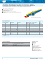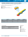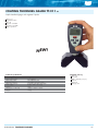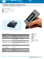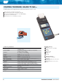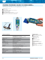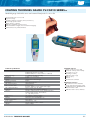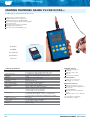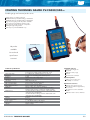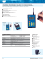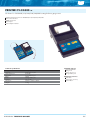
1
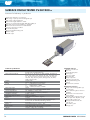
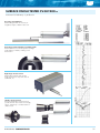
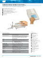
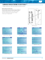
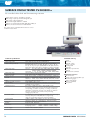
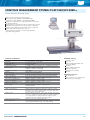
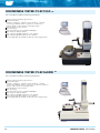
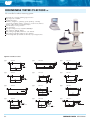
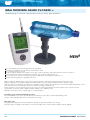
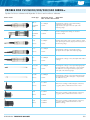
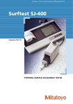
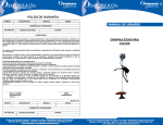
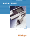
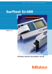
SURFACE FINISH TESTER CV-R190 TM
Simple to operate, high quality universal surface finish tester
Simple but high quality universal roughness tester with excellent price/
quality rating
Tester for use in laboratory or production environment
Multiple styli available;
standard delivery with long and short stylus
Additional roughness parameters available on request
Conforms to international standards ISO, DIN, ASME, JIS
Technical specifications
Measuring System
Measurement parameter
Measurable roughness range
Cut off (L)
Evaluation length (LN)
Filter
Measuring length
Resolution
Indication error
Tracing speed
Stylus
Stylus force
Stylus 1 (standard)
Stylus 2
Worktable
Rotation range
Inclination range
X - Y range
Unit height:
Tracer unit
Tracer height from granite surface
Inclination
Dimensions
Granite base
Column height
Control box
Power supply
Skidless method using inductive pick-up with
interchangeable stylus
Ra; Rz; Rt; Rp; Rv; Rq; RSm; RmaxD; Material ratio curve
Ra 0.01~10um
0.08mm; 0.25mm; 0.8mm; 2.5mm
1L; 2L; 3L; 4L; 5L
Horizontal 60mm (vertical 0,6mm / 600um)
0,001um
Not greater than 6% ±0,004um
0,5mm/sec
R= 2um
0.7mN
For roughness test on plane and round surfaces and in
bores from 10mm diameter, max bore depth= 18mm
For roughness test on plane surfaces, and in bores from 4mm
diameter, max. bore depth= 15mm
360°C
±10°C
15mm
115mm
Min:100mm - max:380mm
±10°C
Standard delivery
Main unit
Tracer unit including 2 styli
Granite base including column
Universal worktable
Control box and drive box
Standard roughness plate
V-block large
(90mm x 60mm x 40mm 45°)
from 4mm - 60mm
V-block small
(40mm x 30mm x 20mm 45°)
from 2mm - 20mm incl. magnetic
surface
PCI i/o controller including
software and wires
CV Instruments certificate
Installation & user manual
Optional accessories
Various styli for different applications
Additional roughness parameters
Optional
Pentium 4 english workstation with
hardware and software pre installed
630mm x 400mm x 100mm
500mm
360mm x 100mm x 80mm
220V 50Hz
B-PROGRAM SURFACE FINISH
73
SURFACE FINISH TESTER CV-SE1200 TM
Instrument for laboratory or production
Instrument for laboratory or production
Wide range of pick-ups with interchangeable styli
Wide range of finish parameters
Measurement length 0.08mm to 25mm
Conforms to international standards ISO, DIN, ASME, JIS
Right angle measurement available for crankshaft
Waviness measurement based on ISO standard
Preset of 9 measuring conditions
Internal thermal printer
Quick rechargeable battery pack
Statistics output
RS-232C output
Technical specifications
Measuring system
Measurement parameter
Display
Filter
Cut-off
Measuring length
Evalutation length
Vertical magnification
Horizontal magnification
Straightness accuracy
Measuring range/resolution
Stylus/skid
Force
Function
Data output
Printer
Power Supply
Weight
74
Skidless/Skidded method using inductive (LVDT)
Pick-Up with interchangeable styli
Ra, Rz, tp, Sm, Rt, Rp, Rv, Pc, HSC, Ra/RMS, RmaxD, R3Z,
Rmax, RSm, Rmr(c), Rdc, Rsk, Rku, Rk, Mr1, Mr2, Rpk, Rvk,
A1, A2, Pa, Pz, Pp, Pv, Pq, RSm, Pmr(c), Pdc, Pt, Pak, Pku,
Wa, Wz, Wp, Wv, Wq, Wsm, Wmr(c), Wdc, Wt, BAC,
ADC, P/R/W profile
Graphic LCD
Gauss, 2RC, ISO13565-1 (DIN4776)
λc
0.08, 0.25, 0.8, 2.5, R+W
λs
ISO3274(96) / ISO97
λc-λf 0.08-0.8, 0.25-0.5, 0.8-8mm
25mm
λc x 1, 2, 3, 4, 5 / arbitrary 0.08mm~16mm
50~100000 (11 steps) / Auto
1~1000 (10 steps), 25mm/λc, 50mm/λc
0.8µm / 10mm
520µm / 0.008µm
R5µm Diamond / R40mm Sapphire
4.0 mN
9 Measuring condition memory, Multi standard analysis,
Profile invert, 99 data SPC, PC linking software
RS-232C
Internal thermal printer, 8dots / 1mm
Ni-H battery pack, 6 hours continuous operation,
100 - 240 Volts with AC adapter
Amplifier 1.8kg, Drive unit 0.7kg
Standard delivery
Amplifier controller unit
Drive unit
Internal thermal printer
Printer paper
Nose piece ANA
Stylus arm AA5
Pick-up body PU-A
Calibration specimen Ra
Rechargeable battery pack
Manual
CV Instruments certificate
Optional accessories
Pick-ups with interchangeable styli,
see next pages
UKAS certified roughness reference
standards
Attachment for roll measurement
FT-22 (>60mm)
Extended cable, length 2m drive unit
can be apart from amplifier (3.5m)
RS-232 cable, length 1.5m
Carrying handle for back side
controller unit
Spare battery pack
Carrying case
SURFACE FINISH B-PROGRAM
SURFACE FINISH TESTER CV-SE1200 TM
Instrument for laboratory or production
Accuracy of straightness
CV-SE1200 guarantees the accuracy of
straightness 0.8µm /100mm in drive unit
Correcting rounded profile to straight profile
CV-SE1200 will correct rounded profile to straight
profile and then calculate, enabling correct
measurement
Right angle measurement
CV-SE1200 can attach slider at right
angles and measure components such as
crankshafts, etc.
Skidless measurement
Both skid and skidless measurements are
possible and can also measure short length,
narrow, small, deep or rounded surface in
skidless mode
B-PROGRAM SURFACE FINISH
75
SURFACE FINISH TESTER CV-SE1700A
TM
Compact multi-function surface finish and form measuring instrument
Instrument for laboratory or production use
Surface roughness, waviness, straightness and form
Wide range of pick-ups with interchangeable styli
Wide range of roughness parameters
Measurement length 0.08mm to 30mm
Conforms to international standards ISO, DIN, ASME, JIS
Waviness measurement based on ISO standard
Quick rechargeable battery pack
Statistics output
RS-232C output
Technical specifications
Measuring system
Measurement parameter
Display
Filter
Profile
Cut-off
Measuring length
Evalutation length
Vertical magnification
Horizontal magnification
Straightness accuracy
Measuring range/resolution
Stylus/skid
Force
Function
Memory
Data output
Power Supply
Weight
76
Skidless/Skidded method using inductive (LVDT) Pick-Up.
with interchangeable styli
Ra, Rz, tp, Sm, Rt, Rp, Rv, Pc, HSC, Ra/RMS, RmaxD, R3Z,
Rmax, RSm, Rmr(c), Rdc, Rsk, Rku, Rk, Mr1, Mr2, Rpk, Rvk,
A1, A2, Pa, Pz, Pp, Pv, Pq, RSm, Pmr(c), Pdc, Pt, Pak, Pku,
Wa, Wz, Wp, Wv, Wq, Wsm, Wmr(c), Wdc, Wt, BAC,
ADC, P/R/W profile
Touch screen LCD
Gauss, 2RC, ISO13565-1 (DIN4776), special Gauss
Un-filtered, filtered (roughness), filtered (centre-line) waviness
λc
0.08, 0.25, 0.8, 2.5, R+W
λs
ISO3274(96) / ISO97
λc-λf 0.08-0.8, 0.25-0.5, 0.8-8mm
30mm
λc x 1, 2, 3, 4, 5 / arbitraty 0.08~16mm
50~100000 (11 steps) / Auto
1~1000 (10 steps), 25mm/λlc, 50mm/λc
0.3µm / 30mm
800µm / 0.0005µm
R2µm Diamond / R40mm Sapphire
0.7mN
Leveling support, Multi standard analysis, Touch panel,
99 data SPC, PC linking software
2 sets of data (optional: 16 sets of measurement conditions)
RS-232C
Ni-H battery pack, 100 - 240 V with AC adapter
Amplifier 4.5kg, Drive unit 0.9kg
Standard delivery
Amplifier controller unit
Drive unit
Calibration specimen Ra
Nose piece ANA
Stylus arm AA2
Pick-up body PU-A2
Manual
CV Instruments certificate
Optional accessories
Pick-ups with interchangeable styli,
see next pages
Memory card for storage of 16 sets
of measuring conditions
UKAS certified roughness
reference standards
Attachment for roll
measurement FT-22 (>60mm)
Extension cable, length 2m
Drive unit can be apart from
amplifier (3.5m)
RS-232 cable, length 1.5m
Carrying handle for back side
controller unit
Battery pack for reserve
purpose
Carrying case
SURFACE FINISH B-PROGRAM
SURFACE FINISH TESTER CV-SE1700A
TM
Compact multi-function surface finish and form measuring instrument
Display and touch control panel
The unique display and touch control panel is very user friendly, even
without an instruction manual. The opening of individual windows by
touching the panel makes selection of all measurement conditions,
parameters and data required for records a simple operation.
No instruction manual required, simply open a “window”
and select, input or change the data.
Chart data outputs
Real time profile recording
Measurement display
Real time rec.
Display of all measuring conditions
Parameter selection
Magnification settings
Cut-off/Filter settings
Probe
Mode selection
B-PROGRAM SURFACE FINISH
77
SURFACE FINISH TESTER CV-SE3500 TM
PC controlled surface finish and form measuring instrument
Surface finish, waviness, straightness and form
Wide range of pick-ups with interchangeable styli
Wide range of finish parameters
Measurement length 0.08mm to 100mm
Conforms to international standards ISO, DIN, ASME, JIS
Waviness measurement based on ISO standard
This system can be upgraded with functions for contour
and form measurement
Technical specifications
Measuring system
Measurement parameter
Measuring range
Measuring range
Evaluation length
Traverse speed
Cut off
Filter
Sampling number/resolution
Auto levelling
Auxiliary function
Bed with column
Leveling stand
Drive unit
Pick up
Dimensions
Power supply
78
Stylus method using inductive (LVDT) pick-up
Ra (Ra75), Rq, Ry, Rmax, Rt, Rz, Rz5, Rz3, R3z, R3zmax,
RzmaxD, RzD, Sk, Ku, Pc, HSC, PPI, Rpm, Sι, Sm, S, Rp, Rv,
θa, θq, Δa, Δq, λa, λq, K, tp,BC,ADC, FFT, Rk, Rpk, Rvk, Mr1,
Mr2, Wca, Wcm, Wea, Wem, Straightness, Gap, Coordinates
Vertical
50, 100, 200, 500, 1000, 2000, 5000, 10000,
20000, 50000, 100000, 200000, 500000,
Horizontal 1, 2, 5, 10, 100, 200, 500, 1000, 2000, 5000
Vertical: 600 um, Horizontal: 100mm
0.25, 0.8, 2.5, 8, 25, 80mm/λc x 1, 2, 3, 4, 5
0.05, 0.1, 0.2, 0.5, 1, 2mm/sec at measuring, 5, 10mm/sec
Finish
0.08, 0.25, 0.8, 2.5, 8mm and un-filtered
Waviness fι 0.8, 2.5, 8, 25mm fh 0.08, 0.25, 0.8, 2.5mm
Gaussian/2CR/Special Gaussian
Max 32000 points/16 bit
Least square method, 2 points method, R curve correction,
quadratic curve correction
Recording of deliberate layout, chart template, mean
processing, statistical processing, discontinued measurement,
recomputing, resistration of pick-up, recording of comments,
calibration of automatic sensitivity, unit changeover between
mm/inch, automatic measurement, notch processing,
changing of profile size
Bed 600mm x 315mm, maximum load 70kg, auto down stop
accuracy ±0.2µm at x100,000 (when using a skid),
range of up and down movement of pick-up 250mm
160mm x 50mm, with V-Shape groove (to the measuring
direction), rotation ±3°, vertical tilt ±3°, Y-axis feed ±3mm
Straightness accuracy 0.2µm/100mm3
R2µm, 0.7mN, Diamond
Measurement section 600mm x 400mm x 593mm, 80kg,
Computing section
900mm x 600mm x 520mm, 30kg
AC90~120V, 50/60Hz, 800VA
Standard delivery
Pick-up
Drive unit
Bed with column
Remote controller
Leveling stand
Controller
Calibration specimen Ra
Manual
CV Instruments certificate
Optional accessories
PC with monitor
Pick-ups with interchangeable styli,
see following pages
UKAS certified finish
reference standards
Laser printer
SURFACE FINISH B-PROGRAM
SURFACE FINISH PICK-UPS
D-series for CV-SE3500 (not exchangeable)
Finish pick-ups
High dynamic performance type
Type:
General use
Radius
Force
Range
PU-DA5/PUDA5S
Normal bore
5µm
4mN
600µm
Type:
Knife edge
Radius
PU-DC5/PU-DC5S
Very small wires
5µm
4mN
600µm
Type:
Bottom of hole
Radius
Force
Range
PU-DE10/PU-DE10S
and groove
10µm
16mN
600µm
Screw thread
Radius
Force
Range
10µm
4mN
600µm
Force
Range
Size
Size
Size
(PU-DF10: Kow Mag.)
Type:
PU-DH10/PU-DH10S
Type:
Low meas. force
Radius
Force
Range
PU-DJ2/PU-DJ2S
softer materials
2µm
0.7mN
600µm
(PU-DJ2U: Low force)
Type:
Long bore
Radius
Force
Range
10µm
10mN
1200µm
Type:
Twin-skid swiveling
Radius
Force
Range
(PU-DB5F: All posture)
for wavy surface
5µm
4mN
600µm
Type:
Crank shaft
Radius
Force
Range
PU-DD5/PU-DD5S
between flanks
5µm
4mN
600µm
Type:
Curve surface
Radius
Force
Range
PU-DG5/PU-DG5S
bottom of groove
5µm
4mN
600µm
Type:
Small bore
Radius
Force
Range
5µm
4mN
600µm
Radius
Force
Range
5µm
4mN
600µm
Radius
Force
Range
800µm
4mN
600µm
PU-DI5/PU-DI5S
Corner end
PU-DK5/PU-DK5S
Type:
Size
(0.3mN)
PU-DQ10/PU-DQ10S
Type:
Size
Waviness
PU-DW800/PU-DW800S
B-PROGRAM SURFACE FINISH
Size
Size
Size
Size
Size
Size
Size
79
SURFACE FINISH PICK-UPS
A-series for CV-SE1200 and CV-SE1700A and CV-SE3500 (exchangeable)
Pick-up body
Type:
Type:
PU-A (normal force)
PU-A2 (low force)
Stylus arms
Type:
Pick-up body not including stylus arm and nose piece (CV-SE1200)
Pick-up body not including stylus arm and nose piece (CV-SE1700)
( ) = low force to be used with body PU-A2
AA2
(CV-SE1700)
2µm
4mN (0.7mN)
ANA/ANH
600µm
General use
Normal bore
Type:
Type:
Radius:
Force:
Nose pc:
Range:
Use:
AC5
5µm
4mN (0.7mN)
ANA/ANH
600µm
Knife edge
Very small wire
Type:
Radius:
Force:
Nose pc:
Range:
Use:
AG5
5µm
4mN (0.7mN)
ANG/ANH
600µm
Curve surface
Deep groves
Type:
Radius:
Force:
Nose pc:
Range:
Use:
AI5
5µm
4mN (0.7mN)
ANH
600µm
Small bore
Type:
Radius:
Force:
Nose pc:
Range:
Use:
AL10
5µm
8mN (5mN)
ANL/ANH
1200µm
Long bore
Type:
ANA
R40mmxR2mm
Skid
General use
Type:
ANG
R0.5mm Skid
Curve/Groove
Type:
ANH
Skidless
measurement
without Skid
Type:
ANK
R40mm Skid
Corner end
Type:
ANL
R40mmxR2mm
Skid
Long bore
Radius:
Force:
Nose pc:
Range:
Use:
Radius:
Force:
Nose pc:
Range:
Use:
AA5
(CV-SE1200)
5µm
4mN (0.7mN)
ANA/ANH
600µm
General use
Normal bore
Nose pieces
80
SURFACE FINISH B-PROGRAM
CONTOUR MEASUREMENT SYSTEM CV-EF150E/EF150ED TM
Contour and form measuring system
High-end contour and form measuring system
Pick up/down range 200mm manual (CV-EF150E)
Pick up/down range 200mm motorized (CV-EF150ED)
Digital error compensation to compensate stylus arc movement
45° tilting mechanism
Synchronization control between pick-up movement and recorder
Selectable measuring direction to save workpiece setting time
Thickness and comparative measurements can be easily done
Perfect safety and warning functions such as:
stylus slowdown mechanism, overload stopping function,
upper-limit warning buzzer
Technical specifications
Accuracy
Measuring range
Resolution
Display magnification
Drive speed
Straightness accuracy
Pick up
Measuring force
Traceable angle
Measuring direction
Pick up/down range
Dimensions measuring part
Dimensions amplifier
Dimensions PC and printer part
Operation conditions
Power supply
Data correct functions
Analysis items
Measuring support functions
Auxiliary functions
Z : 0.1%/5mm, X : 0.2%/5mm
Z: 50mm, X:100mm
0.1µm in X axis
1 to 200x in both Z and X axis (up to 2.000 times optional)
0.02mm to 5mm/s at measuring,
0.02mm to 10mm/s at returning
1µm/100mm
Stylus R25µm, tungsten carbide
10mN to 30mN (adjustable)
Ascend: 77 degrees (smooth surface), descend: 87 degrees
Both upward and downward, both forward and backward
200mm manual (EF-150ED: 200mm motorized)
640mm x 685mm x 315mm, 70kg
436mm x 387mm x 150mm, 10kg
650mm x 500mm x 550mm, 30kg for reference
10°C to 30°C / 80% or less
AC100V 50/60Hz 500VA including 300VA
for PC and printer
Standard delivery
Bed with column
Drive unit
Pick-up (standard PU/FG25 with
stylus arm SB-609)
Amplifier
Contour analysing software
Calibration specimen
CV Instruments certificate
Manual
Optional accessories
PC with monitor
Contour pick-up series and styli and
stylus arms (see next pages)
Alignment function (data point movement, rotation, reverse),
linkage function, stylus curvature radius correction, stylus arm
arc error correction, best fit function
Element analysis (point, line, circle, peak, through, cross point,
cross line, contact point), scaler analysis (coodination distance,
cross angle, distance, radius), ball screw analysis, master
comparison analysis, inspherical surface analysis
Macro function, auto measuring function
Free layout edit, vibrator, measuring range limitation, overload
stop, up/downward measuring, over scale warning
B-PROGRAM SURFACE FINISH
81
PICK-UPS FOR CONTOUR MEASUREMENT
For series CV-EF150E/CV-EF150ED
Stylus arms
Type:
Chisel type
SB-609
Type:
Small hole type
SB-7, 8, 9, 10
Type:
Axe type
SB-1A,4
Type:
Small hole B- type
SB-11,12
Optional:
clamping / protection nose
Type:
Conical type
SB-2A,17,5,18
Type:
Narrow groove type
SB-13,14
Type:
Knife-edge type
SB-3A,6
Type:
Crank type
SB-15A,18
Stylus forms
Type:
S-1B
S-4
Standard styli
H=29mm
H=50mm
Type:
S-1B
S-4
Standard styli
H=29mm
H=50mm
Type:
Styli for narrow
groove
(styli for holes)
H=22.5mm
H=30mm
Type:
S-7
S-8
S-9
S-10
S-11
S-12
Styli for small
H=2mm,
H=3.5mm,
H=5.6mm,
H=8.5mm,
H=13mm,
H=21.5mm,
S-13
S-44
82
Type:
S-3B
S-6
holes
R0.2mm
R0.2mm
R0.5mm
R0.5mm
R0.5mm
R0.5mm
Type:
Knife-edge
styli
H=29mm
H=50mm
Standard offset
styli
S-609
SURFACE FINISH B-PROGRAM
STYLI AND STYLUS ARMS FOR CONTOUR MEASUREMENT
For series CV-EF150E/EF150ED
Item
PU-FG25
Sensor
Measuring range
Measuring force
Stylus traceable angle
Differential transformer
50mm
10 to 30mN (1 gf to 3 gf) when horizontal
Ascend: 77° (smooth surface),
Descend 87°
Vibrator, overload protector, upper limit alarm
Auxiliary function
Applied pick-ups
Type
Name
SB-1A (SA-1A)
SB-2A (SA-2A)
SB-3A (SA-3A)
SB-4A (SA-4A)
SB-609 (SA-609)
SB-5 (SA-5)
SB-6 (SA-6)
SB-7 (SA-7)
Standard stylus arm
Conical stylus arm
Knife stylus arm
Standard stylus arm for large step
Standard offset stylus arm
Conical stylus arm for large step
Knife stylus arm for large step
2.5 stylus arm
B-1 (A-1)
B-1 (A-1)
B-1 (A-1)
B-2 (A-2)
B-609 (A-609)
B-2 (A-2)
B-2 (A-2)
B-3 (A-3)
Combination
Stylus
Measurement
depth
S-1A
21 (20)
S-2A (S-17A) 21 (20)
S-3A
21 (20)
S-4
42 (40)
S-609
42 (40)
S-5 (S-18)
42 (40)
S-6
42 (40)
S-7
0.4
SB-8 (SA-8)
4 stylus arm
B-4 (A-4)
S-8
1
0.025
Carbide
SB-9 (SA-9)
6.3 stylus arm
B-5 (A-5)
S-9
1.6
0.025
Carbide
SB-10 (SA-10)
10 stylus arm
B-6 (A-6)
S-10
2.5
0.025
Carbide
SB-11 (SA-11)
16 stylus arm
B-7 (A-7)
S-11
5
0.025
Carbide
SB-12 (SA-12)
25 stylus arm
B-8 (A-8)
S-12
13.5
0.025
Carbide
SB-13 (SA-13)
Stylus arm for narrow grooves
B-9 (A-9)
S-13
12.5
0.025
Carbide
SB-14 (SA-14)
Stylus arm for narrow grooves B-10 (A-10)
S-14
20
0.025
Carbide
S-1A
S-4
21 (20)
42 (40)
0.025
0.025
Carbide
Carbide
Arm
SB-15A (SA-15A) Crank stylus arm
SB-16 (SA-16)
Crank stylus arm
B-PROGRAM SURFACE FINISH
B-11 (A-11)
B-12 (A-12)
Specifications
R(mm) Material
Others
0.025
0.025
0.025
0.025
0.025
0.025
0.025
0.025
Carbide
Sapphire (carbide)
Carbide
Carbide
Carbide
Sapphire (carbide)
Carbide
Carbide more
CV-EF150 series standard
CV-EF150 series standard
Hole diameter ø 2.5mm
or more
Hole diameter ø 4mm
or more
Hole diameter ø 6.3mm
or more
Hole diameter ø 10mm
or more
Hole diameter ø 16mm
or more
Hole diameter ø 25mm
or more
Groove width 4.5mm
or more
Groove width 4.5mm
or more
83
ROUNDNESS TESTER CV-EC1550
TM
PC controlled roundness measuring instrument
Manual centering and tilting support function
Geometrical features:
Roundness, straightness, cylindricity, spiral cylindricity, co-axiality,
concentricity, parallelism, flatness, squareness, circular runout,
thickness deviation, radius deviation, knife-edge analysis
Powerfull data processing software
Static air bearing
Very high rotating accuracy of (0.04+0.0006H)µm
Max. workpiece diameter 368mm
Max. probing height (OD): 420mm for outer diameter
Max. probing height (ID): 270mm for inner diameter
12 interchangeable styli available for all kinds of special applications
ROUNDNESS TESTER CV-EC1600W
TM
PC controlled roundness measuring instrument
Manual centering and tilting support function
Geometrical features:
Roundness, straightness, cylindricity, spiral cylindricity, co-axiality,
concentricity, parallelism, flatness, squareness, circular runout, thickness
deviation, radius deviation, knife-edge analysis
Powerfull data processing software
Static air bearing
Very high rotating accuracy of (0.04+0.0005H)µm
Max. workpiece diameter 368mm
Max. probing height (OD): 545mm for outer diameter
Max. probing height (ID): 320mm for inner diameter
12 interchangeable styli available for all kinds of special applications
84
SURFACE FINISH B-PROGRAM
ROUNDNESS TESTER CV-EC1550/CV-EC1600W
TM
PC controlled roundness measuring instrument
Technical specifications
Turntable
Rotating method
Rotating accuracy
Rotating speed
Table size
Centering adjustment range
Leveling adjustment range
Min. angle indication
Max. workpiece load
Max. workpiece diameter
Column unit
Straightness
Parallelism
Vertical travel
Travelling speed
Max. probing height (OD)
Max. probing height (ID)
Radial arm unit
Radial travel
Pick up unit
Measuring force
Measuring range
Stylus
Analysis unit
Measuring magnification
Digital filter
Roundness
2CR
Gaussian
Straightness
2CR
Gaussian
Determination method
Geometrical features
Static air bearing
(0.04+0.0006H)µm H: Probing height (mm) (CV-EC1550)
(0.04+0.0005H)µm H: Probing height (mm) (CV-EC1600W)
1 to 10rpm (adjustable)
160mm (CV-EC1550),
180mm (CV-EC1600W)
±2mm
±1.0°
0.1
20kg
368mm
Standard delivery
Measuring unit
Standard probe
Controller
Programm software
Optional accessories
PC with monitor
Interchangeable styli for different
applications:
Ask for separate overview
Chucks ø 0.8 ~ 56mm used for
clamping small diameter workpieces
Reference hemisphere for checking
accuracy
Printer
0.6µm/100mm (1.2µm/250mm) (CV-EC1550)
0.4µm/100mm (0.8µm/300mm) (CV-EC1600W)
0.75µm/100mm (1.5µm/200mm) (CV-EC1550)
0.5µm/100mm (1.0µm/200mm) (CV-EC1600W)
250mm (CV-EC1550), 300mm (CV-EC1600W)
0.5, 1, 2, 5mm/s at measuring
420mm (CV-EC1550) for outer diameter,
545mm (CV-EC1600W) for outer diameter
270mm (CV-EC1550) for inner diameter,
320mm (CV-EC1600W) for inner diameter
130mm (CV-EC1550),
160mm (CV-EC1600W)
100mN or less (adjustable)
1800µm
Radius 0.8mm, Tungsten carbide
100, 200, 500, 1.000, 2.000, 5.000, 10.000, 20.000, 50.000X
N15, N50, N150, N500, N15-500, non-filter
D15, D50, D150, D500, D15-500, non-filter
fh0.025, 0.08, 0.25, 0.8, 2.5, 8mm, non-filter
fh0.025, 0.08, 0.25, 0.8, 2.5, 8mm, non-filter
MZC, LSC, MCC, MIC
Roundness, flatness, cylindricity, co-axiality, concentricity, runout,
squareness, straightness, parallelism, thickness deviation
Utilities
Power supply
AC100V-220V, ±10%, 50/60Hz
Analysis unit
Air supply
Air pressure
4.5 to 9.9kgf/cm² (440 to 970KPa), dry air
4 to 5kgf/cm² (390 to 490KPa), 30Nl/min
Analysis unit
Measuring unit
Amplifier
PC and printer
590mm x 332mm x 918mm, 130kg (WxDxH)
406mm x 342mm x 270mm, 20kg (WxDxH)
Local supply
Operating environment
10°C to 30°C, RH 80% or less
B-PROGRAM SURFACE FINISH
85
ROUNDNESS TESTER CV-EC1800
TM
PC controlled roundness measuring system
Motorized auto centering and tilting support function
Large stage size of 230mm
Geometrical features:
Roundness, straightness, cylindricity, spiral cylindricity, co-axiality,
concentricity, parallelism, flatness, squareness, circular runout, thickness
deviation, radius deviation, knife-edge analysis
Powerfull data processing software
Static air bearing
Very high rotating accuracy of (0.04+0.0006H)µm
Max. workpiece diameter 368mm
Max. probing height (OD): 545mm for outer diameter
Max. probing height (ID): 320mm for inner diameter
12 interchangeable styli available for all kinds of special applications
Styli for roundness testers
Type:
SA-148
Type:
SA-149
Type:
SA-151
Type:
SA-152
Type:
SA-154
Type:
SA-155
Type:
SA-156
Type:
SA-157
Type:
SA-158
Type:
SA-159
Type:
SA-160
Type:
SA-161
86
SURFACE FINISH B-PROGRAM
ROUNDNESS TESTER CV-EC1800
TM
PC controlled roundness measuring system
Technical specifications
Stage
Rotating method
Rotating accuracy
Rotating speed
Stage size
Centering adjustment range
Leveling adjustment range
Max. workpiece load
Max. workpiece diameter
Porus static air bearing / stage rotation
(0.04+0.0006H)µm
H: Height from stage (mm)
1 to 6rpm
230mm dia
±5mm (Motorized)
±1° (Motorized)
25kg
368mm
Column unit
Straightness
Parallelism
Vertical travel
Travelling speed
Max. measuring height
Radial arm unit
0.4µm/100mm (1µm/300mm)
0.7µm/100mm (1.5µm/200mm)
300mm
0.5, 1 and 2mm/s at measuring, 5mm/sec at positioning
545mm for outer, 320mm for inner
Radial travel: 160mm
Pick up unit
Measuring force
Measuring range
Stylus
100mN or less (adjustable)
1800µm
Radius 0.8mm, Tungsten carbide
Analysis unit
Measuring magnification
Digital filter
Roundness
2CR
Gaussian
Straightness
2CR
Gaussian
Determination method
Analysis items
Standard delivery
Measuring unit
Standard probe
Controller
Programm software
Optional accessories
PC with monitor
Interchangeable styli for different
applications:
Ask for separate overview
Chucks ø 0.8 ~ 56mm used for
clamping small diameter workpieces
Reference hemisphere for checking
accuracy
Printer
100, 200, 500, 1K, 2K, 5K, 10K, 20K, 50K
N15, N50, N150, N500, N15-500, non-filter
D15, D50, D150, D500, D15-500, non-filter
fh0.025, 0.08, 0.25, 0.8, 2.5, 8mm, non-filter
fh0.025, 0.08, 0.25, 0.8, 2.5, 8mm, non-filter
MZC, LSC, MCC, MIC
Roundness, flatness, cylindericity, co-axiality, concentricity,
run-out, squareness, straightness, parallelism,
thickness deviation
Utilities
Power Supply
Air pressure at bearing
Air Supply
AC100V, ±10%, 50/60Hz, 1KVA
4 to 5kgf/cm²G (390 to 490KPa), 30Nl/min
4.5 to 9.9kgf/cm²G (440 to 970KPa), Dry air
Dimensions
Measuring unit
Amplifier
PC and printer
600mm x 400mm x 910mm (WxDxH), 150kg
406mm x 342mm x 270mm (WxDxH), 20kg
Local supply
Operating environment
10°C to 30°C, RH 80% or less
B-PROGRAM SURFACE FINISH
87
ROUNDNESS TESTER CV-EC2500
TM
PC controlled roundness measuring system
Motorized auto centering and tilting support function
Large stage size of 260mm
Safety function on pick-up
Geometrical features:
Roundness, straightness, cylindricity, spiral cylindricity, co-axiality,
concentricity, parallelism, flatness, squareness, circular runout, thickness
deviation, radius deviation, knife-edge analysis
Powerfull data processing software
Static air bearing
Very high rotating accuracy of (0.02+0.0003H)µm
Max. workpiece diameter 450mm
Max. probing height (OD): 570mm for outer diameter
Max. probing height (ID): 420mm for inner diameter
12 interchangeable styli available for all kinds of special applications
Option
Measuring direction (IN/OUT) auto exchanger
Radial arm straightness guarantee
(straightness 0.5µm/100mm, squareness 1µm/100mm)
Styli for series roundness testers
Type:
SA-148
Type:
SA-149
Type:
SA-151
Type:
SA-152
Type:
SA-154
Type:
SA-155
Type:
SA-156
Type:
SA-157
Type:
SA-158
Type:
SA-159
Type:
SA-160
Type:
SA-161
88
SURFACE FINISH B-PROGRAM
ROUNDNESS TESTER CV-EC2500
TM
PC controlled roundness measuring system
Technical specifications
Stage
Rotating method
Rotating accuracy
Rotating speed
Stage size
Centering adjustment range
Leveling adjustment range
Max. workpiece load
Max. workpiece diameter
Porus static air bearing / stage rotation
(0.02+0.0003H)µm
H: Height from stage (mm)
1 to 10rpm
260mm dia
±5mm (Motorized)
±2° (Motorized)
30kg
450mm
Column unit
Straightness
Parallelism
Vertical travel
Travelling speed
Max. measuring height
Radial arm unit
0.15µm/100mm (0.4µm/300mm)
0.8µm/200mm
400mm
0.5, 1, 2 and 5mm/s at measuring, 20mm/sec at positioning
570mm for outer, 420mm for inner
Radial travel: 180mm
Pick up unit
Measuring force
Measuring range
Stylus
100mN or less (adjustable)
1800µm
Radius 0.8mm, Tungsten carbide
Analysis unit
Measuring magnification
Digital filter
Roundness
2CR
Gaussian
Straightness
2CR
Gaussian
Determination method
Analysis items
Standard delivery
Measuring unit
Standard probe
Controller
Programm software
Optional accessories
PC with monitor
Interchangeable styli for different
applications:
Ask for separate overview
Chucks ø 0.8 ~ 56mm used for
clamping small diameter workpieces
Reference hemisphere for checking
accuracy
Printer
100, 200, 500, 1K, 2K, 5K, 10K, 20K, 50K, 100K
N15, N50, N150, N500, N15-500, non-filter
D15, D50, D150, D500, D15-500, non-filter
fh0.025, 0.08, 0.25, 0.8, 2.5, 8mm, non-filter
fh0.025, 0.08, 0.25, 0.8, 2.5, 8mm, non-filter
MZC, LSC, MCC, MIC
Roundness, flatness, cylindericity, co-axiality, concentricity,
run-out, squareness, straightness, parallelism, thickness deviation
Utilities
Power Supply
Air pressure at bearing
Air Supply
AC100V, ±10%, 50/60Hz, 1KVA
4 to 5kgf/cm²G (390 to 490KPa), 30Nl/min
4.5 to 9.9kgf/cm²G (440 to 970KPa), Dry air
Dimensions
Measuring unit
Amplifier
PC and printer
930mm x 590mm x 1660mm (WxDxH), 550kg
406mm x 342mm x 270mm (WxDxH), 20kg
Local supply
Operating environment
10°C to 30°C, RH 80% or less
B-PROGRAM SURFACE FINISH
89
HARDNESS TESTERS - DUROMETERS - SURFACE FINISH TESTERS
CONTOUR MEASUREMENT - COATING THICKNESS GAUGES
ULTRASONIC THICKNESS GAUGES - WALL THICKNESS GAUGES
VIBRATION METERS - MICROSCOPES - PROFILE PROJECTORS
visit www.cvinstruments.com
COATING THICKNESS GAUGE “STYLOTEST” TM
Dry film pull-off gauge for steel substrates CV-CG100
Measurement of paint coatings on steel
Designed as a pen with a pocket clip
Magnetic attraction principle featuring a permanent magnet
Patented HOLD mechanism for last reading
For open and recessed measuring areas
Coloured zones for quick go/no-go quality assessment
No power supply or batteries required
Technical specifications
Measuring range
Application
Principle
Accuracy
Min. measuring area
Standards
Ambient temperature
Dimensions
Weight
25-700 microns or 1-28mm
Paint coatings on steel substrates
Magnetic attraction
±10% of reading
25mm diameter
Conforms to DIN-EN-ISO2178
-10°C …80°C
150mm length, diameter 10mm
Approx. 150g
B-PROGRAM THICKNESS GAUGES
Standard delivery
Stylotest gauge
Manual
CV Instruments certificate
Optional accessories
Coating thickness standards
91
COATING THICKNESS GAUGE CV-CG120 A-SERIES TM
Fast and reliable analogue measurements on steel substrates model CV-CG120 series
Highest accuracy with simplest operation
Several models with ergonomic design
No calibration necessary
All gauges without power or battery
One point measurement with a non-wearing probe
A robust metal case and system resistant to mechanical shocks, acids
and solvents
Also non-automatic models available
Type 5 = standard version
Type 6 = automatic version
Min.
base
Version
Range
Application
Tolerance
Minimum
surface
Min. curvature radius
of the sample
5G
6G
0... 100µm
Electroplating and the
paint coatings on steel**
±1µm or 5% of the reading
ø 20mm
5mm convex/25mm concave
0.5mm
5F
6F
0... 1000µm
Paint on steel**
±5µm or 5% of the reading
ø 30mm
8mm convex/25mm concave
0.5mm
6 S3
0.2... 3mm
Enamel, plastic,
±5% of the reading
ø 30mm
15mm convex/25mm concave
1.0mm
6 S5
0.5... 5mm
and rubber
±5% of the reading
ø 50mm
15mm convex/25mm concave
1.0mm
6 S10
2.5... 10mm
on steel *
±5% of the reading
ø 50mm
15mm convex/25mm concave
2.0mm
6 NiFe50
0... 50µm
±(2µm + 8% of the reading)
ø 20mm
10mm convex/25mm concave
0.5mm
Electroplated nickel
on steel
thickness
** steel ST 33 to ST 60
*** special
Technical specifications
Standards
Ambient temperature
Dimensions
Weight
DIN-EN-ISO2178, DIN50982, ASTM B499, E376,
D1186, G12, B530, BS5411, ISO2361
-20°C …100°C
Gauge 215mm x 55mm x 29mm
Approx. 450gr
Standard delivery
CV-CG120
Plastic case
Neck cord
Manual
CV Instruments certificate
Optional accessories
Gauges for specific applications
Leather case for safe transport
of the gauge on a belt
Coating thickness standards
Wet film gauge for measuring the
thickness of wet coatings
92
THICKNESS GAUGES B-PROGRAM
COATING THICKNESS GAUGE CV-CG130 D-SERIES TM
Ready-to-test analogue tester with lever system for direct load application CV-CG130 series
New generation digital patented coating thickness gauges (“7 Series”)
featuring higher accuracy and easy digital display reading
4 models available
No calibration necessary
All gauges with battery
One point measurement with a non-wearing probe
A robust heavy case and system resistant to mechanical shocks,
acids and solvents
Range
Tolerance
Accuracy
Min. measuring contact
Min. radius convex/concave
Min. substrate thickness
CV-CG130 G7
0-300µm
2µm ±3%
0.5µm
20mm
5mm/25mm
0.5mm
CV-CG130 F7
0mm-1.5mm
5µm ±3%
1µm
30mm
8mm/25mm
0.5mm
Technical specifications
Standards
Ambient temperature
Dimensions
Weight
DIN-EN-ISO2178, DIN50982, ASTM B499, E376,
D1186, G12, B530, BS5411, ISO2361
-10°C …50°C
Gauge 210mm x 58mm x 32mm
Approx. 400gr
CV-CG130 S5 7
0.5mm-5.0mm
±4%
5µm
50mm
15mm/25mm
1mm
CV-CG130 S15 7
3.0mm-15.0mm
±4%
20µm
100mm
100mm/150mm
7mm
Standard delivery
CV-CG130
Plastic case
Neck cord
Manual
Batteries
CV Instruments certificate
Optional accessories
4 gauges for specific applications
Leather case for safe transport
of the gauge on a belt
Coating thickness standards
Wet film gauge for measuring the
thickness of wet coatings
B-PROGRAM THICKNESS GAUGES
93
COATING THICKNESS GAUGE TT-210
TM
Handheld gauge with ingrated FN probe
Easy to use
Integrated probe FN
Automatic substrate recognition
Automatic calculation: Mean/Max/Min/No./S.Dev
Upper-lower limit setting and sound alarm
Data output RS-232 to printer TA-220S or PC
Storage function for 500 measuring results
Measurement modes: continuous/single
Battery operated
NEW!
Technical specifications
Operating principle
Measurement range
Measuring system
Minimum resolution
Measuring accuracy
Statistics
Power supply
Display
Dimensions
Weight
94
Magnetic induction/eddy current
0µm to 1250µm
Selectable mm/inch
0.1µm (coating thickness <100µm)
F: ±(3%H+1µm)
N: ±(3%H+1.5µm)
H = nominal value
Average (MEAN), MAX., MIN.,
number of measurements (NO.), standard deviation (S.Dev)
Battery AAA 1.5V (2 pcs)
LCD with back-light
110mm x 50mm x 23mm
100gr
Standard delivery
Main unit
Calibration foil set
AAA 1.5V battery (2 pcs)
Manual
Certificate
Carrying case
Optional
Printer TA-220S with cable
THICKNESS GAUGES B-PROGRAM
COATING THICKNESS GAUGE TT-211
TM
Simple handheld gauge with ingrated F probe
Easy to use
Integrated probe F
Auto off
Mm/inch selectable
Resolution selectable
Battery operated
NEW!
Technical specifications
Operating principle
Measurement range
Measuring system
Minimum resolution
Measuring accuracy
Power supply
Display
Dimensions (L x W x H)
Weight
Magnetic induction
0 to 1250µm
Selectable mm/inch
Selectable 1µm, 5µm, 10µm
F:±(3%H+1µm) H=normal value
Battery AAA 1.5V (2 pcs)
LCD
100mm x 50mm x 23mm
100gr
B-PROGRAM THICKNESS GAUGES
Standard delivery
Main unit
Zero plate
AAA 1.5V battery (2 pcs)
Manual
Certificate
Carrying case
95
COATING THICKNESS GAUGE TT-220 TM
Handheld gauge with integrated F-probe for steel substrates
Integrated probe: NO CABLES !
Any non-magnetic coating on ferrous substrates
Continuous or single measurement modes
Statistics
Real time or batch printing with TA-220 printer
Rechargeable batteries
Printer TA-220
Technical specifications
Operating principle
Application
Measuring range
Minimum resolution
Magnetic induction
Any non-magnetic coating on ferrous substrates
0µm- 1250µm
0.1µm (coating thickness <10µm)
Measuring accuracy
Zero-point calibration ±(3%H+1µm)µm
Two-point calibration
±(1%~3%H+1µm)µm
(H= nominal value)
Average (MEAN), maximum (MAX), minimum (MIN),
number of measurements (NO), standard deviation (S.DEV.)
Real time printing or batch printing on TA-220
Continuous measurement (CONTINUE) and single
measurement (SINGLE)
Automatic switch off
Statistics
Features
Sample
Min. radius workpiece
Min. measuring area
Min. sample thickness
Convex 1.5mm, concave 9mm
7mm diameter
0.5mm
Operating temperature
Power supply
Dimensions
Weight
0°C - 40°C
NiMH batteries, 3.6V
150mm x 53mm x 22mm
150gr
96
Standard delivery
Main unit
Charger
Calibration foil set
Carrying case
Pocket case
Certificate
Manual
Optional accessories
Printer TA-220 with cable
Certified calibration foils
THICKNESS GAUGES B-PROGRAM
COATING THICKNESS GAUGE TT-230 TM
Handheld gauge with integrated N-probe for non-ferrous substrates
Integrated probe: NO CABLES !
Continuous or single measurement modes
Statistics
Real time or batch printing with TA-220 printer
Rechargeable batteries
Printer TA-220
Technical specifications
Operating principle
Application
Measuring range
Minimum resolution
Eddy current
Insulating coatings on non-ferrous substraten
0 - 1250µm
0.1µm (coating thickness <10µm)
Accuracy
Zero-point calibration ±(3%H+1µm)µm
Two-point calibration
±(1%~3%H+1µm)µm
(H= nominal value)
Average (MEAN), maximum (MAX), minimum (MIN),
number of measurements (NO), standard deviation (S.DEV.)
Real time printing or batch printing on TA-220
Continuous measurement (CONTINUE) and single
measurement (SINGLE)
Automatic switch off
Statistics
Features
Sample
Min. radius workpiece
Min. measuring area
Min. sample thickness
Convex 1.5mm, concave 9mm
7mm diameter
0.5mm
Operating temperature
Power supply
Dimensions
Weight
0°C - 40°C
NiMH batteries, 3.6V
150mm x 53mm x 22mm
150gr
B-PROGRAM THICKNESS GAUGES
Standard delivery
Main unit
Charger
Calibration foil set
Carrying case
Pocket case
Manual
Certificate
Optional accessories
Printer TA-220 with cable
Certified calibration foils
97
COATING THICKNESS GAUGE TT-260 TM
Portable gauge with integral printer and external probes series F or N
Robust design with removable integral printer
Large measuring range with several probes available
Direct testing mode and block statistics mode (APPL/BATCH)
Direct print out of statistical values
Data transmission to pc with Dataview software
Technical specifications
Measuring range
Probes available
Tolerance
Resolution
Display
Operation language
Standards
Min. measuring area
Min. curvature radius
Min. substrate thickness
Calibration
Statistics
Data memory
Limits
Interface
Operating temperature
Power supply
Dimensions
Weight
98
0µm - 1250µm with standard probe F1, N1
(10.000µm max)
Several probes available for F (ferrous; on steel/iron)
and N (non-ferrous metals)
F1: ±(1µm + 3% of reading)
N1: ±(1.5µm + 3% of reading)
0.1µm
Alphanumeric with 4 large digits
English
Conforms to DIN, ISO, ASTM, BS
ø5mm (standard probe N1), ø7mm (standard probe F1)
Convex: 3mm, concave: 50mm
Type F: 0.5mm, type N: 0.3mm
Factory setting, zero and foil calibration
Number of measurements, mean, standard deviation,
maximum and minimum of maximum 3000 readings
5 blocks of 99 readings can be stored for later reference
Adjustable with acoustic alarm
RS-232
0°C - 40°C
NiMH rechargeable batteries, 1.25V (4 pcs)
270mm x 86mm x 47mm
530gr
Standard delivery
Main unit
Probe (F or N series selectable)
Charger
Zero plate
Calibration foils
Carrying case
Manual
Certificate
Optional accessories
Several probes for different
applications
PC software Dataview for online and
data transfer
Certified calibration foils in various
thickness
THICKNESS GAUGES B-PROGRAM
HARDNESS TESTERS - DUROMETERS - SURFACE FINISH TESTERS
CONTOUR MEASUREMENT - COATING THICKNESS GAUGES
ULTRASONIC THICKNESS GAUGES - WALL THICKNESS GAUGES
VIBRATION METERS - MICROSCOPES - PROFILE PROJECTORS
visit www.cvinstruments.com
COATING THICKNESS GAUGE CV-CG200 SERIES TM
Handheld gauge CV-CG200 series with integrated probe F or N or FN
Integrated probe F or N or FN
Ergonomic design
Automatic substrate recognition (ferrous/non-ferrous)
User friendly operation menu
Online statistics on display
Calibration standards stored in housing
Manual available in English, French or German language
Data transmission by infrared interface and RS-232C
Integrated probe
Calibration foils inside
Technical specifications
Models with integrated probe
Models with external probe
Measuring range
Tolerance
Resolution
Display
Operating language
Standards
Min. measuring area
Min. curvature radius
Min. substrate thickness
Calibration
Statistics
Data memory
Limits
Interface
Ambient temperature
Power supply
Dimensions
Weight
100
CV-CG200F (ferrous; on steel/iron)
CV-CG200N (non-ferrous metals),
CV-CG200FN (ferrous and non-ferrous combined)
Same as above but now model CV-CG210
0 - 2000µm (µm/mills selectable)
±(2µm + 3% of reading)
0.1µm
Alphanumeric with back-light
English
DIN, ISO, ASTM, BS
20mm diameter
Convex: 5mm,
Concave: 60mm in centre, 35mm at the edges
Type F: 0.5mm, type N: 50µm
Factory setting, zero and foil calibration
Number of measurements, mean, standard deviation,
maximum and minimum; block statistics
(5….30) data per block
90 readings or 45 block values
Adjustable with acoustic alarm
RS-232C (to printer CV-CG300 or pc)
0°C - 50°C
2AA batteries, 1.5V
Gauge 160mm x 35mm x 40mm
Approx. 200gr
Standard delivery
Gauge + probe (F or N or FN)
Soft pouch with strip and wriststrap
Zero plate (one or two
according to model)
Calibration foils (2 pcs)
Batteries (2pcs)
Manual
CV Instruments certificate
Optional accessories
PC software for online and data
transfer
Interface cable for standard PC
Portable data printer CV-CG300 with
interface cable
Calibration foils in various thickness
THICKNESS GAUGES B-PROGRAM
COATING THICKNESS GAUGE CV-CG210 SERIES TM
Handheld gauge CV-CG210 series with external fixed probe F or N or FN
Fixed external probe F or N or FN
Ergonomic design
Automatic substrate recognition (ferrous/non-ferrous)
User friendly operation menu
Online statistics on display
Calibration standards stored in housing
Manual available in English, French or German language
Data transmission by infrared interface
Technical specifications
Models available
Measuring range
Tolerance
Resolution
Display
Operating language
Standards
Min. measuring area
Min. curvature radius
Min. substrate thickness
Calibration
Statistics
Data memory
Limits
Interface
Ambient temperature
Power supply
Dimensions
Weight
CV-CG210F (ferrous; on steel/iron),
CV-CG210N (non-ferrous metals),
CV-CG210FN (ferrous and non-ferrous combined)
0 - 2000µm (µm/mills selectable)
±(2µm + 3% of reading)
0.1µm
Alphanumeric with back-light
English
DIN, ISO, ASTM, BS
20mm diameter
Convex: 5mm,
Concave: 60mm in centre, 35mm at the edges
Type F: 0.5mm, type N: 50µm
Factory setting, zero and foil calibration
Number of measurements, mean, standard deviation,
maximum and minimum; block statistics
(5….30) data per block
90 readings or 45 block values
Adjustable with acoustic alarm
Infrared to printer CV-CG300 or pc
0°C - 50°C
2AA batteries, 1.5V
Gauge 160mm x 35mm x 40mm
Approx. 200gr
B-PROGRAM THICKNESS GAUGES
Standard delivery
Gauge + probe (F or N or FN)
Soft pouch with strip and wriststrap
Zero plate (one or two
according to model)
Calibration foils (2 pcs)
Batteries (2pcs)
Manual
CV Instruments certificate
Optional accessories
PC software for online and data
transfer with infrared interface cable
Portable data printer CV-CG300 with
infrared interface cable
Calibration foils in various thickness
101
COATING THICKNESS GAUGE CV-CG310/320 TM
Portable gauge with external probes series
Robust design, top quality instrument
CV-CG310 memory for 1 reading only
CV-CG320 memory for 10.000 readings
Large measuring range with 20 probes available
Direct testing mode
Large memory with statistics computation
Coating-through-coating feature
Data output to printer CV-CG300 or pc
CV-CG300 printer
20 probes
available
See technical
specification
overview !
Technical specifications
Models available
Measuring range
Tolerance
Resolution
Display
Operation language
Standards
Min. measuring area
Min. curvature radius
Min. substrate thickness
Calibration
Statistics
Data memory
Interface
Ambient temperature
Power supply
Dimensions
Weight
102
20 probes available for F (ferrous; on steel/iron),
N (non-ferrous metals) and FN (combined), see list
0 - 1600µm with standard probe F1.6 or N1.6
±(1µm + 1% of reading) with standard probes
0.1µm
Alphanumeric with 4 large digits
English
DIN, ISO, ASTM, BS
5mm x 5mm (with standard probe)
Convex: 3mm, concave: 50mm
Type F: 0.5mm, type N: 50µm
Factory setting, zero and foil calibration
Number of measurements, mean, standard deviation,
maximum and minimum of maximum
10.000 readings (only CV-CG320)
1 individual reading (CV-CG310)
10.000 individual readings, 1 batch only (CV-CG320)
See next page for models with extended memory capacity
RS-232
0°C - 50°C
1 x 9V alkaline battery, AC adapter
Gauge 150mm x 82mm x 35mm
Approx. 270gr
Standard delivery
Gauge excluding probe
Zero plate
Calibration foils (2 pcs)
Manual
CV Instruments certificate
Optional probes
Probes (F or N or FN series
selectable), see overview
Optional accessories
Carrying case with accessories
20 probes for different applications,
see overview
Printer CV-CG300
PC software for online and data
transfer
Calibration foils in various thickness
See next page for models with
extended memory capacity
THICKNESS GAUGES B-PROGRAM
COATING THICKNESS GAUGE CV-CG330/340 TM
Portable gauge with external probes series
Robust design, top quality instrument
CV-CG330 memory 10.000 readings, 100 batches
CV-CG340 memory 10.000 readings, 500 batches
Large measuring range with 20 probes available
Direct testing mode and block statistics mode
Large memory with block statistics computation
Coating-through-coating feature
Data output to printer CV-CG300 or pc
CV-CG300 printer
20 probes
available
See technical
specification
overview !
Technical specifications
Models available
Measuring range
Tolerance
Resolution
Display
Operation language
Standards
Min. measuring area
Min. curvature radius
Min. substrate thickness
Calibration
Statistics
Data memory
Limits
Interface
Ambient temperature
Power supply
Dimensions
Weight
20 probes available for F (ferrous; on steel/iron),
N (non-ferrous metals) and FN (combined), see list
0 - 1600µm with standard probe F1.6 or N1.6
±(1µm + 1% of reading) with standard probes
0.1µm
Alphanumeric with 4 large digits
English
DIN, ISO, ASTM, BS
5mm x 5mm (with standard probe)
Convex: 3mm, concave: 50mm
Type F: 0.5mm, type N: 50µm
Factory setting, zero and foil calibration
Number of measurements, mean, standard deviation,
maximum and minimum of maximum 10.000 readings
10.000 individual readings and max. 100 batches with
individual values (CV-CG330)
10.000 individual readings and max. 500 batches with
individual values (CV-CG340)
Adjustable with acoustic alarm
RS-232
0°C - 50°C
1 x 9V alkaline battery, AC adapter
Gauge 150mm x 82mm x 35mm
Approx. 270gr
B-PROGRAM THICKNESS GAUGES
Standard delivery
Gauge excluding probe
Zero plate
Calibration foils (2 pcs)
Manual
CV Instruments certificate
Optional probes
Probes (F or N or FN series
selectable) see overview
Optional accessories
Carrying case with accessories
20 probes for different applications,
see overview
PC software for online and data
transfer
Calibration foils in various thickness
103
COATING THICKNESS GAUGE CV-CG250/250B
TM
Basic model portable gauge with external probe / statistics & output optional
Fixed external probe F or N or FN
Ergonomic design
Automatic substrate recognition (ferrous/non-ferrous)
User friendly operation menu
Display with black-light
Calibration standards stored in housing
Language selectable English, French or German
Model CV-CG250 only:
Online statistics on display
Data transmission by RS-232
Data output to printer CV-CG300 (with cable) or pc
CV-CG250B
CV-CG300 printer
Basic version
without
statistics,
no output
Technical specifications
Range
Accuracy
Min. radius
Min. measuring contact
Min. substrate thickness
Display
Unit
Calibration
Statistics
Interface
Power supply
Dimensions
104
Type F (ferrous)
0...3000µm / 120 mils
Type N (non-ferrous)
0...2000µm / 80 mils
Type FN (ferrous/non-ferrous) 0...2000µm / 80 mils
± 2µm (0.08 mils) or 4% of the value
5mm (0.2 inch) convex and 25mm (1 inch) concave
ø 20mm (0.8inch)
0.5mm (20 mils)
Alphanumerical with 4 digits (11mm/0.44inch)
µm - mils to choice
Standard, 1-point, 2-point
X average, standard dev., n (max. 9999), min, max
RS-232 C
2 alkaline batteries (for over 10.000 readings)
Gauge:
64mm x 115mm x 25mm
Probe:
15mm dia. x 62mm (0.6inch x 2.5inch)
Standard delivery
Gauge + probe
(F or N or FN)
Zero plate (one or
two according to model)
Calibration foils (2 pcs.)
Batteries (2 pcs)
RS-232-C
(model CV-CG250 only)
Manual
CV Instruments certificate
Optional accessories
Portable data printer
CV-CG300 with
interface cable
Calibration foils in various
thickness
Soft pouch with strip and
wriststrap
THICKNESS GAUGES B-PROGRAM
PRINTER CV-CG300
TM
CV Printer for CV-CG250/310/320/330/340/600 coating thickness gauge series
Reliable and fast mini-printer for CV-CG250/310/320/330/340/600
Prints numerical values
EPSON print head
RS-232 input
Power adapter included
Technical specifications
Display
Functions
Data transmission
Print head
Paper
Power
Charger
Dimensions
Weight
4 digit lcd
Paper feed, on/off
RS-232C
5 x 7 matrix Epson
50mm
Storage battery 5V
5V / 2.4A
85mm x 152mm x 48mm
0.5kg
B-PROGRAM THICKNESS GAUGES
Standard delivery
Printer CV-CG300
Charger 5V
Printer rolls (2 pcs)
Storage battery 5V
Optional accessories
Data cable
Printer paper (set of 5)
Printer ribbon
105
WALL THICKNESS GAUGE CV-CG500
TM
Handheld gauge for wall and coating thickness testing of metals, glass and plastics
NEW!
New: Considerably improved measuring properties through SIDSP !
Non-destructive wall thickness measurement up to 4mm and/or 10mm
Up to 20 measurements per second
For all non-magnetic materials such as plastics, wood, glass, ceramics, glass fiber, carbon fiber laminates, non-ferrous metals, etc.
For hollow parts and containers of all kinds such as bottles, cans, injection moulding products, etc.
Also for plastic sheets, automotive body parts, glass panes, SMC plastics other large-sized components, etc.
Complete measuring technique is integrated in the sensor
With this totally new SIDSP procedure, all necessary measuring signals are created and completely processed in the sensor itself.
Only the completely processed digital readings are transferred to the base unit for display, statistical evaluation and data storage.
Unlike the commonly used analogue procedures, the new SIDSP procedure excludes any error influences on the measuring data during transfer over the
probe cable. The result is a measuring accuracy and constancy of readings, unmatched so far.
Further innovations to increase measuring accuracy: the new process technology manufacture the reference balls used to results an increased
reproducibility of over 0.5% and the calibration method enabling up to 5 calibration points.
Calibration can be done over the complete range or over defined ranges.
Innovative menu control and data filing system
The new CV-CG500 is very easy to opearate. The menu-controlled user surface offers a user-friendly data filing system
similar to common PC applications and a contextsensitive on-line help.
Data processing
The gauge features display of minimum and maximum readings, an offset mode (related to the set value),
automatic storage of readings into the statistics as well as visual display of the continuously taken readings (real-time diagram).
106
THICKNESS GAUGES B-PROGRAM
WALL THICKNESS GAUGE CV-CG500
TM
Handheld gauge for wall and coating thickness testing of metals, glass and plastics
Technical specifications
Measuring principle
Measuring rate
Number of readings memorized
in the statistics
Magneto-static
Up to 20 readings per second
1, 2, 5, 10, 20 readings/sec to choice
Measuring range FH4 probe
0...1.5mm with 1.5mm reference ball
0...2.5mm with 2.5mm reference ball
0...4.0mm with 4.0mm reference ball
Measuring range FH10 probe
Low range sensitivity
Measuring tolerance of FH4 probe
Measuring tolerance of FH 10 probe
Calibration modes
Display
Measuring units
Data memory
Statistical evaluation
Languages
Interface
Operating temperature
Storing temperature
Dimensions and weight of gauge
Dimensions and weight ofFH4 probe
Dimensions and weight of FH10 probe
Dimensions of plastics carrying case
Power supply
0...2.5mm with 2.5mm reference ball
0...4.0mm with 4.0mm reference ball
0...10.0mm with 6.0mm reference ball
0.1µm
0...1.5mm :
0...2.5mm :
0...4.0mm :
0...2.5mm :
0...4.0mm :
0...10.0mm
± (5µm + 1 % of reading)
± (5µm + 1 % of reading)
± (10µm + 1 % of reading)
± (5µm + 1 % of reading)
± (10µm + 1 % of reading)
: ± (20µm + 1 % of reading)
Zero, 2-point, 3-point, 4-point and 5-point calibration
LCD 160x160 pixel with backlight
Metric (µm, mm), imperial (mils, inch)
100,000 readings
Numeric, trend and histogram
English, German, French
Cable, (RS232 TTL) and/or combination port for foot
switch, external contact, Infrared (IrDA 1.1)
-10°C ... +60°C
-20°C ... +80°C
153mm x 89mm x 32mm / 310 gr (batteries incl.)
17mm ø x 96mm / 90 gr
29,5mm ø x 125mm / 300 gr
365mm x 450mm x 140mm
4 x AA (LR06), power unit (90-240V~ / 48-62Hz)
*1.
Set of standards for 5 points calibration/FH-4 probe and ball diameter 4 mm.
1 Precision standard in approx. 0.43mm, 0.75mm, 1.3mm, 2.2mm and 3.6mm.
*2.
Set of standards for 5 points calibration/FH-10 probe and ball diameter 6 mm.
1 Precision standard in approx. 1.0mm, 1.7mm, 3.0mm, 5.2mm and 9.0mm.
B-PROGRAM THICKNESS GAUGES
Standard delivery
CV-CG500
Batteries AA LR06(4 pcs)
Instruction manual available in
German/English/French
Short manual
Carrying case
Magnetic screwdriver
Optional accessories
for CV-CG500
Portable printer CV-CG550
Probe FH4 including operating stand
Probe FH10 including operating
stand
Rubber protection case
Standard accessories
for probe FH4 *1
Calibration cap:
0.3mm, 1mm, 3mm
3 zero calibration standards:
ø1.5mm, ø2.5mm, ø4mm
Set of 100 balls ø1.5mm
Set of 100 balls ø2.5mm
Set of 50 balls ø4mm
Standard accessories
for probe FH10 *2
Calibration cap:
1mm, 3mm, 8mm
4 zero calibration standards:
ø2.5mm, ø4mm, ø6mm, ø9mm
Set of 100 balls ø2.5mm
Set of 50 balls ø4mm
Set of 25 balls ø6mm
Set of 10 balls ø9mm
107
PROBES FOR CV-CG310/320/330/340 SERIES TM
N-probes for non-ferrous substrates
Probe model
108
Probe type
Measuring range/
Application
Min. area for measurement
Extremely thin insulating coatings, e.g. paint or
anodising coatings on non-ferrous metal high resolution
(0.1µm) in the lower part of the measuring range
N 02
0-200µm
Non-ferrous
ø 2mm
N 08Cr
0-80µm
Non-ferrous
ø 5mm
N 1.6
0-1600µm
Non-ferrous
ø 5mm
N2
0-2000µm
Insulating coatings, e.g. paint, on non-ferrous
Non-ferrous
ø 2mm
NOT AVAILABLE!
N 1.6/90
0-1600µm
Non-ferrous
ø 5mm
N 2/90
0-2000µm
Non-ferrous
ø 5mm
N 10
0-10mm
Non-ferrous
ø 50mm
N 20
0-20mm
Non-ferrous
ø 70mm
N 100
0-100mm
Non-ferrous
ø 200mm
CN 02
10-200mm
Non-ferrous
ø 7mm
Extremely thin chrome coatings on copper, aluminium
or brass
thin insulating coatings, e.g. paint or anodising
coatings on non-ferrous metal high resolution (0.1µm) in
the lower part of the measuring range
Thin insulating coatings, e.g. paint or anodising
coatings on non-ferrous metal especially appropriate for
measurements in tubes and pipes or objects which are
difficult to access high resolution (0.1µm) in the lower
part of the measuring range
Insulating coatings, e.g. paint, on non-ferrous metal
especially appropriate for measurements in tubes and
pipes or objects which are difficult to access
Insulating coatings, e.g. rubber, plastics, glass, on
non-ferrous metal
Insulating coatings, e.g. rubber, plastics, glass, on
non-ferrous metal
Insulating coatings, e.g. rubber, plastics, glass,
compounds etc., on non-ferrous metal
Non-ferrous metal coatings, e.g. copper, on insulating
substrates
THICKNESS GAUGES B-PROGRAM
PROBES FOR CV-CG310/320/330/340 SERIES TM
F-probes for ferrous substrates and FN-probes for ferrous and non-ferrous substrates
Probe model
Probe type
FN 1.6
B-PROGRAM THICKNESS GAUGES
Measuring range/
Application
Min. area for measurement
0...1600µm
Combined
Probe
ø 5mm
FN 1.6 P
0...1600µm
Combined
Probe
ø 30mm
F 05
0...500µm
Ferrous
ø 3mm
F 1.6
0...1600µm
Ferrous
ø 5mm
F3
0...3000µm
Ferrous
ø 5mm
F 1.6/90
0...1600µm
Ferrous
ø 5mm
F 2/90
0...2000µm
Ferrous
ø 5mm
F 10
0...10mm
Ferrous
ø 20mm
F 20
0...20mm
Ferrous
ø 40mm
F 50
0...50mm
Ferrous
ø 300mm
Non-magnetic coatings on steel and insulating
coatings on non-ferrous metal
high resolution (0.1µm) in the lower part of the
measuring range
Powder coatings before baking on steel and
non-ferrous metal
Extremely thin metals, oxide or paint coatings on small
steel objects high resolution (0.1µm) in the lower part of
the measuring range
Non-magnetic coatings on steel high resolution
(0.1µm) in the lower part of the measuring range
Non-magnetic coatings on steel, thick paint and enamel
coatings
Non-magnetic coatings on steel especially appropriate
for measurements in tubes and pipes or objects which
are difficult to access high resolution (0.1µm) in the
lower part of the measuring range
Non-magnetic coatings on steel especially appropriate
for measurements in tubes and pipes or objects which
are difficult to access
Anticorrosive coatings in tanks and pipe construction,
e.g. glass, plastics, rubber and concrete on steel
Anticorrosive coatings in tanks and pipe construction,
e.g. glass, plastics, rubber and concrete on steel
Anticorrosive coatings in tanks and pipe construction,
e.g. glass, plastics, rubber andconcrete on steel
antinoise coatings
109