1
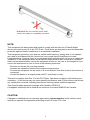
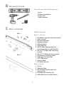
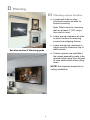
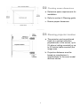
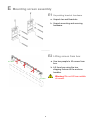
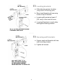
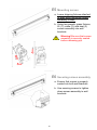
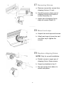
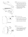
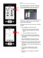
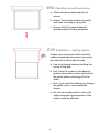
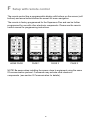
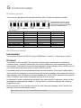
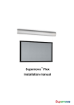
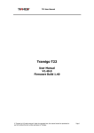
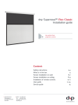
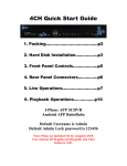
Supernova™ Flex
Installation manual
Contents
Page
Section
A Important Safety Instructions
3
B Required tools
5
C Box contents
5
D Planning
6
E Mounting screen assembly
8
F Setup with remote control
15
G Communication
17
H Planning guide
21
2
A Important Safety Instructions
Read these instructions.
Keep these instructions.
Heed all warnings.
Follow all instructions.
Do not use this apparatus near water.
Clean only with dry cloth.
Do not block any ventilation openings. Install in accordance with the manufacturer’s
instructions.
Do not defeat the safety purpose of the grounding-type plug. A grounding type plug
has two blades and a third grounding prong. The third prong is provided for your
safety. If the provided plug does not fit into your outlet, consult an electrician for
replacement of the obsolete outlet.
Protect the power cord from being walked on or pinched particularly at plugs,
convenience receptacles and the point where they exit from the apparatus.
Unplug this apparatus during lightning storms or when unused for long periods of time.
WARNING! To reduce the risk of fire or electric shock, do not expose this apparatus
to rain or moisture. Do not operate screen before it is installed on wall.
Follow all installation instructions. Incorrect installation can lead to severe
injury and/or permanent product damage and will invalidate the dnp warranty.
Be sure that the wall studs or other mounting fixtures are suitable for mounting the
screen and …
Be sure that the screen is mounted correctly and securely to the wall or the dnp
warranty will be invalidated.
If an extension cord or power strip is used as the disconnect device, the disconnect
device must remain readily operable.
The screen must be installed using a functional ground connection. Do not install
without a ground connection.
Do not pull or tug on screen when mounted on wall.
Do not restrict the screen from moving.
Do not scratch or bend screen material during handling.
Operate within specified temperature and humidity range (see section I).
Do not attempt to disassemble any part of the screen (electric shock hazard).
Do not permit children to play with screen controls.
Examine the screen for imbalance or signs of wear during operation. If needed, adjust
before operating.
3
WARNING! Do not connect power until
screen assembly is completely mounted.
NOTE:
This equipment has been tested and found to comply with the limits for a Class B digital
device, pursuant to part 15 of the FCC Rules. These limits are designed to provide reasonable
protection against harmful interference in a residential installation.
This equipment generates, uses and can radiate radio frequency energy and, if not installed
and used in accordance with the instructions, may cause harmful interference to radio
Communications. However, there is no guarantee that interference will not occur in a particular
installation. If this equipment does cause harmful interference to radio or television reception,
which can be determined by turning the equipment off and on, the user is encouraged to try to
correct the interference by one or more of the following measures:
- Reorient or relocate the receiving antenna.
- Increase the separation between the equipment and receiver.
- Connect the equipment into an outlet on a circuit different from that to which the receiver is
connected.
- Consult the dealer or an experienced radio/TV technician for help.
This device complies with Part 15 of the FCC Rules. Operation is subject to the following two
conditions: (1) this device may not cause harmful interference, and (2) this device must accept
any interference received, including interference that may cause undesired operation.
This Class B digital apparatus complies with Canadian ICES-003.
Cet appareil numérique de la classe B est conforme à la norme NMB-003 du Canada.
CAUTION:
Changes or modifications not expressly approved by dnp denmark as could void the user’s
authority to operate this equipment according to part 15 of the FCC rules.
4
B Required tools
You will need the following tools:
Level
Phillips screwdriver
Power drill
Tape measure
C Box contents
Check box for:
Box 1
Box 1 – Screen
1
1
1
1
3
2
2
4
2
2
2
1
1
1
Box 2
Installation manual (this document)
User manual
Screen assembly
Remote control
AAA batteries
Wall brackets
#8-32 Allen head screws for
securing screen to wall bracket
#8 x 2½” Phillips wall mounting
screws
#8 x 2½” Phillips leveling screws
Washers for leveling screw
End-caps for lower bar
3/32” Allen key
Power cable
IR cable with clip
Box 2 - Cover
1 Cover
2 Security clips
2 #8-32 Allen head screws for
security clip
2 Washers for security clip
2 End-plates for on-wall version
5
D Planning
D1 Planning screen location
a. Locate wall studs or other
structural member suitable for
bracket mounting.
Note: Select studs for mounting
that are at least 4” [101 mm] in
from end of cover.
b. Leave enough clearance at ends
to permit access for removing
screws from shipping fixtures.
c. Leave enough top clearance to
tighten security screws on top of
wall brackets.
See also section H Planning guide
d. Custom spacers are available if
the screen assembly needs to be
spaced further away from the wall
to clear obstructions when rolling
down.
NOTE! See separate manual for inceiling installation!
6
D2 Checking screen dimensions
a. Determine space requirements for
installation.
b. Refer to section H Planning guide
c. Ensure proper clearances.
_____
D3 Planning projector location
a. The projector can be positioned
freely on a vertical centerline,
perpendicular to the screen, up to
5% above (ceiling mounted) or up
to 5% below (table mounted) the
image area.
b. Projection distances must be
based on manufacturer’s
specifications for the exact model
and lens choice.
7
E Mounting screen assembly
E1 Unpacking bracket hardware
a. Unpack two wall brackets.
b. Unpack mounting and securing
hardware.
_____
E2 Lifting screen from box
a. Use two people to lift screen from
box.
LIFT HERE
b. Lift from box using the two
shipping fixtures at the ends as
handles.
LIFT HERE
8
Warning! Do not lift from middle
of screen.
E3 Leveling brackets
a. After planning screen location...
(using section H Planning guide)
b. Mount wall bracket with securing
screw at top of bracket.
c. Locate wall brackets at least 4”
[101 mm] in from end of cover.
d. Level wall brackets to each other
and tighten leveling screws.
____
E4 Securing wall brackets
a. Secure each wall bracket with two
wall mounting screws.
b. Tighten all screws.
9
E5 Mounting screen
a. Leave shipping fixtures attached
to ends while mounting screen
assembly to wall.
b. Using two people, grasp fixtures,
lift (1), rotate (2), and seat (3)
screen assembly into wall
brackets.
Warning! Be sure that screen
assembly is securely seated
before releasing grip.
3
1
2
_____
E6 Securing screen assembly
a. Ensure that screen is properly
seated into both wall brackets.
b. Use securing screws to tighten
down screen assembly to wall
brackets.
10
E7 Removing fixtures
1
2
a. Remove connection screws from
shipping fixtures (1) and …
b. Carefully remove lower part of
shipping fixtures from ends of
screen assembly (2).
3
c. Upper part of shipping fixture
stays on master frame (3)
_____
E8 Mount end-caps
a. Unpack two end-caps and screws.
b. Attach end-caps to lower bar and
use Allen key to tighten the
screws.
_____
E9 Replace shipping fixture
NOTE! Only for on-wall installation
a. Detach screws in upper par of
shipping fixture. Keep screws.
b. Unpack end-plates in box 2.
c. Re-use screws from above to
attach end-plates.
11
E10 Attaching security clips
a. Slide security clips into the cover
catches at the ends of the cover.
b. Be sure ends of security clips are
seated in the cover catches.
c. Loosely position security clips
near ends of cover.
_____
E11 Seating cover
a. Lift cover onto screen assembly.
b. Mate the catches on back of cover
to lip on top of screen assembly.
c. Rotate cover down until it stops.
_____
E12 Securing cover
a. Position security clips on outside
of screen assembly ends and …
b. Secure with #8-32 Allen head
screws and washers.
12
E13 Powering up (Plug in)
PRESS
to
BEGIN
Insert the plug of the IR receiver cable into
the mini-jack socket in the screen (located
next to the RS-232 socket). See below.
Place the infrared eye in the metal holder and
ensure good visible contact to the remote
control can be obtained.
Plug the power cord into the screen- and wall
sockets.
a. After plugging in the power cord,
• press the House symbol to go to the
“Home page” then press [SN Flex] to
begin
Then
PRESS
•
then press [UP] on the remote
b. The screen calibrates by automatically
moving down 3” [76 mm] and then to the
top position.
c. Press [DOWN] and the screen will roll
down to the factory set bottom position.
d. If the screen is not in the top position when
plugging in, Press [UP] & the screen will
move down 3” [76 mm] and slowly back up
to the top.
e. There will be a delay before screen
movement occurs after pressing the
button.
f. See section F for setting a new bottom
position.
13
E14 Checking smooth operation
a. Check extension and retraction of
screen.
b. Ensure that screen retracts smoothly
and does not snag on any parts.
c. Ensure that full screen extension
operates without hitting obstacles.
_____
E15 Aesthetics – hiding cables
Unless your screen has steel wires the
cables suspending the screen can easily
be coloured to blend with the wall.
a. Use a felt-tipped marker matching the
colour of the wall.
b. Hint: Drop the screen to the desired
position and make a colour test behind
the cover before colouring all of the
cable.
c. Hint: If you want the flexibility to change
the cable colour, use a washable
marker.
d. Do not use regular paint to colour the
cables because the movement of the
cables could be affected.
14
F Setup with remote control
The remote control has a programmable display with buttons on the screen (soft
buttons) and arrow buttons below the screen for menu navigation.
The remote is factory programmed for the Supernova Flex and can be further
programmed for use with other electronic components. Please see the remote
control manual for programming instructions.
MACRO
MENU
HOME PAGE
◄
►
◄
PAGE 1
►
PAGE 2
◄
►
PAGE 3
NOTE! Be aware when installing the screen close to equipment using the same
IR communication protocol. Commands may activate other electronic
components. (see section G Communication for details).
15
Setting a new bottom position
•
•
•
•
Press [ ] to go to “Home Page”
Then Press [Flex]
Press the right arrow button and shift to Page 2.
Press & hold [▲] or [▼] until screen is at desired position then press save.
Note: the screen will shift up and down slightly (10mm) to signify that it
read the command.
• Shift back to Page 1 and test setting with [UP] & [DOWN] keys.
Changing the Speed
Supernova Flex has three possible speed “Low, Medium and High”. The screen
will arrive set for the “Medium” speed. To set another speed:
•
•
•
•
Press [ ] to go to “Home Page”
Then Press [Flex]
Press the right arrow button and shift to Page 3.
Press the desired speed. Note: the screen will shift up and down slightly,
½” (10mm), to signify that it reads the command.
• Shift back to Page 1 and test setting with the [UP] & [DOWN] keys.
16
G Communication
IR remote control
The screen is operated by the standard protocol, RC5. Please see below for details:
The illustration shows a typical
pulse train of an RC5 message.
This example transmits command
0x35-53 to address 0x05-5.
Description
Full up
Full down
Raise
Lower
Save bottom position
Select low speed
Select medium speed
Select high speed
LCD remote
UP
DOWN
▲
▼
SAVE
LOW
MEDIUM
HIGH
RC5 address
0x1B - 27
0x1B - 27
0x1B - 27
0x1B - 27
0x1B - 27
0x1B - 27
0x1B - 27
0x1B - 27
RC5 command
0x15 - 21
0x16 - 22
0x17 - 23
0x18 - 24
0x19 - 25
0x1A - 26
0x1B - 27
0x1C - 28
RS-232 serial control
Introduction
The interface is based on RS-232 using 115200 Baud, 1 start bit, 1 stop bit and no parity.
Protocol
The protocol is line-oriented. The controller expects single command lines containing a
command word - optionally followed by one or more parameters, each separated by one or
more spaces. Command lines must be terminated by a single carriage return (ASCII code 13)
and may be optionally followed by a linefeed (ASCII code 10).
Command words as well as parameter words are case-sensitive. They may be abbreviated.
The controller will respond to command lines with a status message, which starts with a threedigit response code, followed by a human readable text, which further describes the response
code. In addition, some status messages may be sent at any time.
In response to some commands the controller may send multi-line responses, where the first
message line starts with the number 3. The last line of a multi-line response will contain a
single period only.
When powered up, the controller will send an initial welcome message, which includes the
firmware version and the serial number.
200 dnp Flex Vx.y.z #0123456789 ready
17
User commands
This section describes most common user commands in detail.
Items enclosed in square brackets are optional. Items enclosed in angle brackets are to be
replaced by specific values. For example, the command syntax for lowering the screen is:
d[own] <n>
Possible command lines are
down 100
do 50
d 200
Status messages are sent by the controller in response to a command line. Each message
line starts with a 3-digit code, where the first digit specifies the response type:
1xx - Informational status message
2xx - OK message (command accepted)
3xx - OK message, multi-line response will follow
4xx - Error message, the last two digits further specify the error
8xx - Controller is temporarily busy and unable to accept new commands
9xx - Special service information
b[ottom]
Moves the screen to the bottom position.
bottom
101 Moving to 2642
203 Screen stopped at 2647
d[own] <n>
Moves the screen down by <n> steps.
down 500
101 Moving to 494
203 Screen stopped at 488
h[elp]
Lists all available commands.
help
300 Command list follows
info
Shows system information
bottom
Moves to the bottom position
top
Moves to the top position
move <n>
Moves to absolute position <n>
up <n>
Moves up by n steps
down <n>
Moves down by n steps
set bottom
Sets current position as bottom position
set speed <s>
Sets the screen speed to s (1..100)
x
Halt (aborts current motion)
.
18
i[nfo]
Shows system information.
info
301 System settings follow
Firmware=0.3.6
Serial=0000000016
Bottom=2502
SpeedLimit=50
Position=2502
Speed=0
.
m[ove] <n>
Moves the screen to absolute position <n>.
move 2000
101 Moving to 2000
203 Screen stopped at 1994
move 2000
420 Already there
s[et] b[ottom]
Sets current position as bottom position.
move 2500
101 Moving to 2500
203 Screen stopped at 2502
set bottom
202 OK
800 Saving settings, please wait
801 Settings saved, ready again
s[et] s[peed] <s>
Sets maximum screen speed. <s> can be in the range of 1 to 100.
set
202
800
801
speed 50
OK
Saving settings, please wait
Settings saved, ready again
t[op]
Moves the screen to the top position.
top
101 Moving to 0
203 Screen stopped at -6
u[p] <n>
Moves the screen up by <n> steps.
up 2000
101 Moving to 0
203 Screen stopped at -6
19
x
Immediately stops current screen movement.
bottom
101 Moving to 2642
x
203 Screen stopped at 1034
12V-Trigger control
To operate the Supernova Flex through contact closures, a pluggable terminal block
connection is available. The terminal block has seven positions for wires.
For contact closure operation, the five terminals on the left side of the terminal block are used.
The operation of the screen through this port is as follows:
Label
Name
C
Common
Raise
Momentarily connect to common to raise the screen
incrementally. The screen will rise as long as this contact
remains shorted to common.
Lower
Momentarily connect to common to lower the screen
incrementally. The screen will lower as long as this contact
remains shorted to common.
Top
Momentarily connect to common to send the screen to the
preprogrammed top position. It is not necessary to continue
connecting to common after motion begins.
Bottom
Description
Common wire, shorted to others for control.
Momentarily connect to common to send the screen to the
preprogrammed bottom position. It is not necessary to
continue connecting to common after motion begins.
For 12-Volt trigger operation, the two terminals on the right side of the terminal block are used.
Applying 5V to 12V (AC or DC) to these two terminals will cause the screen to lower to the
bottom position; removal of the voltage will cause the screen to return to the top position.
Polarity is not important (either polarity works for DC voltage).
20
H Planning guide
Use below information and size specifications to determine the placement of the
screen and the wall brackets.
NOTE! See the Supernova Flex datasheet for screen specifications and
dimensions for your size of screen.
21
Certified to CAN/CSA std. C22.2 no. 60065
Conforms to UL std. 60065
3124639
22
www.dnp.dk
www.dnpscreens.us
23
Rev. 2.7b
dnp denmark as – Skruegangen 2 – DK – 2690 Karlslunde – Denmark – Tel: +45 46 16 51 00 – Fax: +45 46 16 52 00 – [email protected]
24