1
Instrument Control Software User’s Manual
SOAR Adaptive Module (SAM)
Revision 3.7.0, November 2013
Change Record
Version
Date
Description
3.5.1
July 22, 2013
Fix LASER Tab documentation
R.Cantarutti
3.6.0
September 11, 2013
Add SLCH Interlock Override control indicator
R.Cantarutti
3.7.0
November 28, 2013
Reorder/update sections 2.4 to 2.14. Update sections
2.15.2, 2.18, 2.10 and 4.1.1
R.Cantarutti
ii
Owner Name
Table of Contents
Chapter: 1 Getting Things Running...........................1
1.1 Starting the Instrument Control Software.......................................................................................1
1.2 Stopping the Instrument Control Software......................................................................................1
1.3 Environment Variable ICSOFT_HOME.........................................................................................1
1.4 Command Line Options..................................................................................................................1
Chapter: 2 GUI Reference...........................................3
2.1 MAIN > Menu Bar..........................................................................................................................3
2.1.1 MAIN > Menu Bar > AO-Loop Menu....................................................................................3
2.1.2 MAIN > Menu Bar > TT-Loop Menu.....................................................................................4
2.1.3 MAIN > Menu Bar > WFS Menu............................................................................................4
2.2 MAIN > General Status Pane..........................................................................................................4
2.2.1 MAIN > General Status > Comm-Links.................................................................................4
2.2.2 MAIN > General Status > Last Error Message Box................................................................4
2.3 MAIN > General Control Pane.......................................................................................................5
2.4 MAIN > Control Loops...................................................................................................................5
2.5 MAIN > Selector Mirror Pane.........................................................................................................5
2.6 MAIN > Loop Control Buttons.......................................................................................................5
2.7 MAIN > Events & Commands Box................................................................................................6
2.8 MAIN > Guide Probes Status Parameters Pane..............................................................................6
2.9 MAIN > WFS Status Pane..............................................................................................................7
2.10 MAIN> SOAR M3 Pane...............................................................................................................8
2.11 MAIN> LLT M3 Pane...................................................................................................................8
2.12 MAIN > Loop Parameters Pane....................................................................................................8
2.13 MAIN > SLCH Parameters...........................................................................................................8
2.14 MAIN > TCS Parameters..............................................................................................................9
2.15 MAIN > Operation Tab.................................................................................................................9
2.15.1 Scripts Controls...................................................................................................................10
2.15.2 Graphic View.......................................................................................................................10
2.16 MAIN>Catalogs Tab (DEPRECATED!).....................................................................................11
2.17 MAIN>Guide Probes Tab............................................................................................................12
2.18 MAIN> WFS / TURSIM Tab......................................................................................................14
2.19 MAIN > LLT / LASER Tab.........................................................................................................16
2.20 MAIN> ADC / TCS....................................................................................................................18
2.21 MAIN > Telemetry Tab...............................................................................................................19
2.22 MAIN>Maintenance...................................................................................................................19
2.22.1 MAIN > Maintenance > [RTC | AOM | LM | TCS] Manager.............................................19
2.22.2 MAIN > Maintenance > Sync [RTC | AOM]......................................................................20
Chapter: 3 Common Operations...............................21
3.1 Centering a Guide Probe...............................................................................................................21
iii
3.2 Parking a Guide Probe...................................................................................................................21
3.3 Guide Probe APD Activation........................................................................................................21
3.4 Guide Probe APD Bias Calibration...............................................................................................21
3.5 Using TURSIM.............................................................................................................................21
3.6 Adjusting TURSIM light source....................................................................................................22
3.7 Flattening the DM.........................................................................................................................22
3.8 Flattening the DM taking rotation into account............................................................................22
3.9 Recording a new Flatten DM file..................................................................................................22
3.10 Resetting the WFS.......................................................................................................................22
3.11 Tracking with the ADC................................................................................................................23
3.12 Selecting the output port..............................................................................................................23
3.13 Selecting a Guider Star From a User Defined Catalog...............................................................23
3.14 Selecting a Guide Star From the Yale Bright Star Catalog.........................................................23
3.15 Selecting a Guide Star Interactively Using GMAP.....................................................................24
3.15.1 NGS Mode...........................................................................................................................24
3.15.2 LGS Mode...........................................................................................................................24
Chapter: 4 Configuration Files and Macros.............27
4.1 Configuration Files........................................................................................................................27
4.1.1 icsoft.ini.................................................................................................................................28
4.1.2 soar_comms.ini......................................................................................................................29
4.1.3 viserver.ini.............................................................................................................................29
4.1.4 telemetry.ini...........................................................................................................................29
4.1.5 instruments.ini.......................................................................................................................30
4.1.6 lltfoc.ini..................................................................................................................................30
4.1.7 rgatedelay.ini..........................................................................................................................30
4.1.8 wfsfoc.ini...............................................................................................................................31
4.1.9 Dmflat_rot1.txt......................................................................................................................31
4.1.10 faults.ini...............................................................................................................................31
4.2 Macros...........................................................................................................................................32
4.3 Scripts............................................................................................................................................32
4.3.1 Coded Names.........................................................................................................................32
4.3.2 Instrument Initialization Scripts............................................................................................32
4.3.3 User defined scripts...............................................................................................................32
4.4 Catalog Files..................................................................................................................................32
4.4.1 User Guide Star Files.............................................................................................................32
4.4.2 stacklist.dat............................................................................................................................33
Chapter: 5 Log Files..................................................35
5.1 Type Alarm Events........................................................................................................................35
Chapter: 6 Acquisition Camera Software................37
6.1 User Interface................................................................................................................................37
6.1.1 Main GUI...............................................................................................................................37
6.1.2 Image Display........................................................................................................................37
iv
6.1.2.1Cross-Hair.......................................................................................................................37
6.1.2.2Pop-Up Menu..................................................................................................................37
6.2 Configuration File.........................................................................................................................37
Chapter: 7 Troubleshooting......................................39
7.1 Can't Find Guide Stars...................................................................................................................39
7.1.1 NGS Mode.............................................................................................................................39
7.2 Tweaking Quad-Sensor Offsets.....................................................................................................39
Chapter: 8 Glossary...................................................40
v
Chapter: 1 Getting Things Running
Chapter: 1
Getting Things Running
This user manual is intended to describe the use of the SAM Instrument Control Software(ICSOFT)
from a user's point of view. It is not a programming manual. For implementation details please read the
IC Software Programmer Manual (ICSPM).
1.1 Starting the Instrument Control Software
a) Turn on the instrument control computer an wait for the system to boot.
b) Log on as user ao
c) Open a shell window and invoke the instrument control application with the following
command:
% cd /home/ao/ICsoft/Bin
% labview ICsoft.vi -- <options>
d) Optionally you can press the button labeled ICSOFT in the task bar.
1.2 Stopping the Instrument Control Software
To stop the ICSOFT application click the EXIT button. A dialog box will prompt for confirmation.
Select YES.
1.3 Environment Variable ICSOFT_HOME
The location of the ICSOFT is defined by an environment variable included in the .cshrc file. Right
now this variable is pointed to the /home/ao/ICsoft directory. To check its value type at the command
prompt of your favorite terminal the following command
% setenv ICSOFT_HOME /home/ao/ICsoft
1.4 Command Line Options
The ICSOFT accepts a few command line options to customize its behavior. Valid options are listed
below
-aom The ICSOFT starts with the AOM manager disabled.
-lm
The ICSOFT starts with the LM manager disabled.
-rtc
The ICSOFT starts with the RTC manager disabled.
-tcs
The ICSOFT starts with the TCS manager disabled.
For example to start the ICSOFT with all outgoing connections turned off you would type
% ./samics ---aom -lm -rtc -tcs
1
ICSOFT User Manual 3.7.0, November 2013
Chapter: 2 GUI Reference
Chapter: 2
GUI Reference
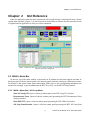
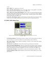
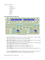
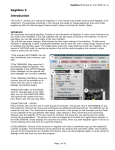
When the application starts the user is presented with a single window containing the most relevant
system status variables (Figure 1). If the boot process ended with no failures then the operational state
is signaled and the application is ready to receive commands.
Figure 1: Main GUI. The most relevant status variables are displayed. The actual user
interface may look a bit different.
2.1 MAIN > Menu Bar
At the very top of the main window is the menu bar. It includes several menu options and most of
them just open a Labview remote panel to the desired graphic interface running in a different processor.
For details on the actual remote panel functionality please refer to the corresponding subsystem user
manual. For example, to get information on the RTC Loop GUI, see the RTSOFT user manual.
2.1.1 MAIN > Menu Bar > AO-Loop Menu.
Show AO Loop GUI. Opens a Labview remote panel to the RTC Loop GUI window.
Reconstructor Error. Opens a Labview remote panel presenting the RTC Reconstructor Error
Analysis window.
Show DM GUI. Opens a Labview remote panel presenting the RTC DM GUI window.
AO Loop Data Recorder. Opens a Labview remote panel presenting the RTC AO Loop Data
3
ICSOFT User Manual 3.7.0, November 2013
Chapter: 2 GUI Reference
Recorder GUI window.
2.1.2 MAIN > Menu Bar > TT-Loop Menu
Show TT Loop GUI. Opens a Labview remote panel presenting the RTC TT GUI window.
TT Probes Flux. Opens a Labview remote panel presenting the RTC TT flux charts window.
Statistics. Opens a Labview remote panel presenting the RTC probes error signal GUI window.
TT Loop Data Recorder. Opens a Labview remote panel presenting the RTC TT loop data
recorder GUI window.
2.1.3 MAIN > Menu Bar > WFS Menu
Show WFS GUI. Opens a Labview remote panel presenting the RTC WFS GUI window.
Show WFS Display. Opens a Labview remote panel presenting the RTC WFS Display window.
Slopes Statistics. Opens a Labview remote panel presenting the RTC Slopes Statistics GUI
window.
Subapertures Flux and FWHM. Opens a Labview remote panel presenting the RTC
Subapertures Flux and FWHM GUI window.
Histogram. Opens a Labview remote panel presenting the RTC Frame Histogram GUI window.
Bias Calibration. Opens a Labview remote panel presenting the RTC Bias Calibration Tool
window.
Static Aberrations. Opens a Labview remote panel presenting the RTC Static Aberrations Tool
window.
2.2 MAIN > General Status Pane
2.2.1 MAIN > General Status > Comm-Links
The comm-link indicators uses a color code to represent the status of the connection: RED =
Problems, WHITE = No Conn, GREEN = OK.
Clients Indicator. Indicates the status of the connections to remote systems: AOM, LGSM,
RTC, and TCS.
Servers Indicator. Indicates the status of incoming connections to the ICS: SAMI and
VISITOR.
2.2.2 MAIN > General Status > Last Error Message Box
The box displays the last warning or error message produced by the system. When no warnings or
errors are present the box is solid green. When a warning message is produced the box goes yellow.
Finally when an error messages is produced the box goes red.
ICSOFT User Manual 3.7.0, November 2013
4
Chapter: 2 GUI Reference
The box stays red and displaying the error messages even if the fault condition is fixed. To refresh
the box contents and color press the Clear Alarms button (see section 2.3 below). To gather more
information based on the current condition of this box the user should always look at the instrument
diagram in the Operation Tab (see section 2.15.2 below) and at the faults table in the Maintenance Tab
(see section 2.21 below).
2.3 MAIN > General Control Pane
Clear Alarms Button. Clears the alarm signal. Note that if an error condition is still present in
the system, the alarm condition will be signaled again.
Maintenance Button. Currently DISABLED.
EXIT Button. Prompts the user to terminate the application.
2.4 MAIN > Control Loop Status Pane
SOAR M3 Loop LED Indicator. Indicates the M3 control loop status: open or closed. This
indicator goes ON when the guider probes tip tilt loop is closed. When a fault the word ERR! is
set.
SOAR Mount Loop LED Indicator. Indicates the Mount control loop status: open or closed .
This indicator goes ON when the SOAR mount loop is closed. When a fault the word ERR! is
set.
LLT M3 Loop LED Indicator. Indicates the Laser Launch Telescope (LLT) M3 control loop
status: open or closed. This indicator goes ON when the LLT M3 loop is closed. When a fault
the word ERR! is set.
DM Loop LED Indicator. Indicates the AO control loop status: open or closed. This indicator
goes ON when the AO loop is closed. When a fault the word ERR! is set.
Running Script LED Indicator. It turns ON to indicate that a LUA script is being executed.
2.5 MAIN > Selector Mirror Pane
Selector Mirror String Indicator. Shows the currently selected instrument: SAMI or VI. The
selected instrument defines the output selector mirror position. When the output selector
mechanism is active the indicator blinks. When a fault condition has been detected the indicator
background color turns red and the word ERR! appears.
2.6 MAIN > Control Loop Buttons Pane
SOAR M3 Loop Button Control. [Open | Close] the SOAR M3 mirror control loop.
Telescope, TT, Laser and AO parameters get automatically recorded into the log file.
SOAR Mount Loop Button Control. [Open | Close] the SOAR mount control loop. Telescope,
TT, Laser and AO parameters get automatically recorded into the log file.
Guide Stars Button Control. Use this button to select and show the Guide Probes Tab.
5
ICSOFT User Manual 3.7.0, November 2013
Chapter: 2 GUI Reference
Figure 2: Scripts can redirect their output to this box by using the LOG command.
LLT M3 Loop Button Control. [Open | Close] the LLT M3 mirror control loop. Telescope, TT,
Laser and AO parameters get automatically recorded into the log file.
AO Loop Button Control. [Open | Close] the AO control loop. Telescope, TT, Laser and AO
parameters get automatically recorded into the log file.
Laser Button Control. Use this button to select and show the LLT/Laser Tab.
OPEN ALL LOOPS Button Control. Use this button to execute the associated
OpenAllLoops.lua LUA script. The script will typically contain commands to open all the
control loops.
2.7 MAIN > Events & Commands Box
This box serves as an information window to display commands executed in the system, the result of
certain operations, events recorded by the ICS, etc. Scripts also can direct their output to this box by
using the LOG command (see section ).
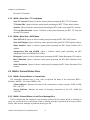
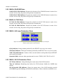
2.8 MAIN > Guide Probes Status Pane
Figure 3: During normal operation the Over Current LED has to be off. To clear an over current
condition use the Reset control in the Guide Probes Tab.
[GP1 | GP2] Flux [K-e/sec]. Shows the average total flux received by guide probe [1 | 2] in [KICSOFT User Manual 3.7.0, November 2013
6
Chapter: 2 GUI Reference
e/ sec]
[GP1 | GP2] X / Y. Centroid error in X and Y
[GP1 | GP2] HV LED Indicator. Shows if the high voltage is being applied to the APDs.
When a fault condition has been detected the word ERR! is set.
[GP1 | GP2] Over Current LED Indicator. Shows is the over current protection has been
activated. During normal operation this LED has to be off. To clear an over current condition
use the Reset control in the Guide Probes Tab (see section 2.16 below). When a fault condition
has been detected the word ERR! is set.
Lock [GP1 | GP2] Button Control. Use this button to lock the guide star on the probe. When
locked, the tilt error signal coming from the probe will be used for compensating the tilt.
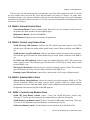
2.9 MAIN > WFS Status Pane
Figure 4: Uncheck the Residual Only check box to show the total aberrations for each mode
(residual + DM).
LGS Boolean Indicator. The indicator will show a picture of the artificial guide star whenever
the Lase diodes are on and the two shutters are opened. Nothing is shown otherwise.
WFS Spots Display. Picture indicator presenting a preview of the current WFS display,
updated every second.
WFS Flux [Ke-/sec] Indicator. Presents the average flux per sub-aperture in the WFS.
WFS Focus [mm] String Indicator. Shows the current WFS focus position in [mm]. When the
mechanism is moving it blinks. When the mechanism has been disabled the indicator turns grey.
When a fault had been detected the background color turns to red and the word ERR! is set.
Residual Only Check Box. Uncheck this box to show the total aberrations (residuals + DM)
Zernike Coefficients Table. Modal estimation of the first three Zernike Modes (tilt in x and y
plus defocus)
7
ICSOFT User Manual 3.7.0, November 2013
Chapter: 2 GUI Reference
2.10 MAIN> SOAR M3 Pane
SOAR M3 EL Slide Indicator. Presents the elevation of the SOAR M3 mirror in units of arc
seconds. In close loop, the pointer will typically sit around zero.
SOAR M3 AZ Slide Indicator. Presents the azimuth of the SOAR M3 mirror in units of arc
seconds. In close loop, the pointer will typically sit around zero.
2.11 MAIN> LLT M3 Pane
LLT M3 EL Slide Indicator. Presents the elevation of the LLT M3 mirror in units of arc
seconds. In close loop, the pointer will typically sit around zero.
LLT M3 AZ Slide Indicator. Presents the azimuth of the LLT M3 mirror in units of arc
seconds. In close loop, the pointer will typically sit around zero.
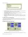
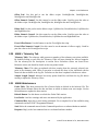
2.12 MAIN > AO Loop Parameters Pane
Figure 5: The RTSOFT produce estimates once every few seconds for r0, wind speed
and the variance of the corrected modes.
r0 [m] Indicator. Seeing estimate produced by the RTSOFT once every few seconds.
Wind [m/s] Indicator. Wind speed estimate produced by the RTSOFT once every few seconds.
VAR C.M.[rad2] Indicator. Variance of the corrected modes in rad2 produced by the RTSOFT
once every few seconds..
Operation Mode. Indicates what operation mode is active: TSNGS, NGS, TSLGS or LGS.
2.13 MAIN > SLCH Parameters Pane
SLCH State Indicator. String indicating the current state of the SLCH interlock.
Time [s] Indicator. Remaining time before the SCLH software forbids the LASER from
operate.
SLCH Override LED Indicator. Shows the current state of the SLCH interlock override
(OVERRIDE=green & blinking or ENGAGE=solid black). When a fault the word ERR! is set.
ICSOFT User Manual 3.7.0, November 2013
8
Chapter: 2 GUI Reference
2.14 MAIN > TCS Parameters Pane
MOUNT RA Indicator. String indicating the current mount RA coordinate in units of hours.
MOUNT DEC Indicator. String indicating the current mount Dec coordinate in units of
degrees.
MOUNT HA Indicator. String indicating the current mount HA coordinate in units of hours.
LST Indicator. String indicating the local sidereal time in units of hours.
MOUNT EL Indicator. String indicating the current mount elevation in units of degrees.
MOUNT AZ Indicator. String indicating the current mount azimuth in units of degrees.
Rotator Angle Indicator. String indicating the current rotator mechanical angle in units of
degrees.
SAM PA Indicator. String indicating the current SAM position angle in units of degrees.
SOAR M3 Position Indicator. String indicating the current SOAR M3 turret position
UT Indicator. String indicating the current universal time in units of hours.
F.OFFSET [X | Y] Indicators. String indicating the current field offset as reported back by
GMAP after an FO operation.
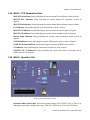
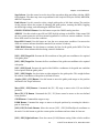
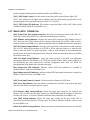
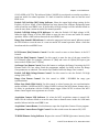
2.15 MAIN > Operation Tab
Figure 6: Clicking on a device picture (Guide Probes, DM, TURSIM, ADC, FP, WFS, Shutter and OSM) brings up
a pop-up menu with available actions.
Operation Mode Selector Box. Selects the operation mode: NGS, TSNGS, LGS or TSLGS, by
running the associated configuration script: NGS.lua, TSNGS.lua, LGS.lua and TSLGS.lua
9
ICSOFT User Manual 3.7.0, November 2013
Chapter: 2 GUI Reference
Set Operation Mode Button Control. Use this button to execute the script associated to the
selected operation mode.
Instrument Selector Box. Selects between dedicated science CCD and visitor instrument. The
box lists the instruments defined in the instrument.ini file (see section 4.1.5 below). When an
instrument is selected the script associated to that instrument in the configuration file is used to
set the SAM module.
Set Instrument Button Control. Use this button to execute the script associated to the selected
instrument.
LGS Configuration Combo Box. Use this drop down menu two select between three available
configurations: 7[Km], 10[Km] and 13[Km]. Each selection will run associated Lua script
LGS7KM.lua, LGS10KM.lua and LGS13KM.lua. Look for the scripts in the ICsoft/scripts
directory.
Set Distance Button Control. Use this button to execute the script associated to the LGS
configuration selected using the LGS Distance combo box.
2.15.1 Scripts Controls
The ICSOFT includes a LUA scripting engine. When a script is executed the output is presented at
the Events & Commands Box.
Scripts. Use this control to select a script from the scripts directory.
RUN. Execute the selected macro.
STOP. Abort the current macro execution.
Pause. Allows to pause and resume the execution of a macro.
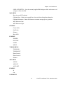
2.15.2 Graphic View
The user is presented with a graphic view showing the current instrument setup, including light path,
light sources and element positions. The display area of the picture control is context sensitive so when
the mouse pointer is placed over a certain device the correspondent label and information pane are
lighted.
Clicking on a device picture (Guide Probes, DM, TURSIM, ADC, FP, WFS, Shutter and OSM)
brings up a pop-up menu with available actions. When a device is not initialized or faulted its device
label blinks indicating its current state. The WFS label for example, blinks to indicate that a mechanism
(focus, reference beam arm/stage, f/10 adjustment) is ACTIVE. When a fault condition has been
detected in at least one of the mechanisms, besides blinking the label background color turns solid red
and the label text changes to ERR!
DM MENU
ROTFLAT – Flattens the DM based on a previously saved list of voltages including a
correction factor based on the current rotator angle.
ZERODM – Set all DM voltages to zero.
ICSOFT User Manual 3.7.0, November 2013
10
Chapter: 2 GUI Reference
SAVE AS FLATTEN - Save the currently applied DM voltages to disk as the new set of
voltages to flatten the DM.
WFS MENU
Reset (re-start WFS readout)
Calibrate Bias – Obtain an averaged bias to be used when doing bias subtraction.
Calibrate References – Reset all references to current average spot x-y position.
WFS Reference Arm
WFS Reference Light
GP MENU
Center Probe
Park Probe
Dimmer
Reset APD
ES MENU
ESOPEN
ESCLOSE
SLEEP
WAKE
TURSIM MENU
TURSIM IN
TURSIM OUT
Phase Screen 1
Phase Screen 2
Dimmer
ADC MENU
ADCIN
ADCOUT
AUTO SET
FP MENU
In
Out
USER MENU
11
ICSOFT User Manual 3.7.0, November 2013
Chapter: 2 GUI Reference
RECORD
DONE TARGET
SpotOffset
NoOffset
SLEEP
WAKE
2.16 MAIN>Guide Probes Tab
Figure 7: Turn the APD high voltage ON and the reset the over current condition to start using the guide probes.
Actual pane may differ a bit.
[GP1 | GP2] X [mm]. Shows the current X coordinate of guide probe [1 | 2] stage in [mm].
Blinks when moving. Solid red when fault. Grayed when disabled.
[GP1 | GP2] Y [mm]. Shows the current Y coordinate of guide probe [1 | 2] stage in [mm].
Blinks when moving. Solid red when fault. Grayed when disabled.
[GP1 | GP2] Z [mm]. Shows the current focus position for guide probe [1 | 2] in [mm]. Blinks
when moving. Solid red when fault. Grayed when disabled.
[GP1 | GP2] RA. Shows the current RA coordinate of guide probe [1 | 2].
[GP1 | GP2] Dec. Shows the current Dec coordinate of guide probe [1 | 2].
[GP1 | GP2] Epoch. Shows the epoch of the current RA/Dec coordinates of guide probe [1 | 2].
[L | R | U | D] Offset Buttons. Offset the guide probe position by a user defined step size. The
step size is defined by the value Step Selector control (small, medium, large).
ICSOFT User Manual 3.7.0, November 2013
12
Chapter: 2 GUI Reference
Step Selector. Use this control to set the size of the step when doing and offset with the LRUD
Offset buttons. The three step sizes are predefined in the icsoft.ini file by the SLOW, MEDIUM,
and FAST keywords.
Link Selector. Use this control to select a single guide probe or link their actions. The position
of this selector affects the actions of offsetting the guide probes, resetting the APDs, toggling
the APDs high voltage, and calibrating the APD bias levels.
GMAP CATALOGS Button. Use this button to open the GMAP catalog interface.
APD HV. Use this switch to turn ON and OFF the high voltage to the APDs. When turned ON
the over current protection will be activated regardless of a real over current condition. Use the
Reset APD control to clear that condition.
Reset APD Control. Use this button to clear the over current state condition. On success the
APD over current indicator should be turned off (see section 2.8 above).
TAKE BIAS Button. Use this button to estimate the bias for the guide probe APDs. The bias
calibration is then subtracted before doing centroid calculations.
[GP1 | GP2] Target RA. Presents the RA coordinate of the guide star candidate to be acquired
with guide probe.
[GP1 | GP2] Target Dec. Presents the Dec coordinate of the guide star candidate to be acquired
with probe.
[GP1 | GP2] Epoch. Presents the epoch of the RA/Dec coordinates of the guide star candidate
to be acquired with the guide probe.
[GP1 | GP2] Weight. Set the relative weight assigned to the guide probe. This weight defines
the relative contribution of the probe to the total tilt error.
Acquire [GS1 | GS2] Button. Use this button to move the guide probe stages to the position
indicated in the Target indicators.
Move [GP1 | GP2] Buttons. Commands the [P1 | P2] stage to move to the X,Y user defined
positions.
Move [F1 | F2] Button. Commands the [P1 | P2] focus control to move to the user defined
focus position.
STOP Button. Command the stages to stop.
PARK Button. Command the stages to move to the park position by executing the GP<N>
park.lua script.
[GP1| GP2] To Stack Buttons. Move the current [GP1 | GP2] RA/Dec/Epoch coordinates to
the stack. Use this button to grab the current probe coordinates and save them for later use.
[GP1 | GP2] Light Indicator. Show the current [0-100] dimmer setting. When a fault condition
13
ICSOFT User Manual 3.7.0, November 2013
Chapter: 2 GUI Reference
has been found the background is solid red and the word ERR! is set.
[GP1 | GP2] Light Control. Use this control to turn the guider probe reference light [ON |
OFF] . The intensity of the light can be adjusted from the guide probe pop-up menu in the
picture diagram in the Operation Tab (see section 2.15.2 above).
[GP1 | GP2] Light LED Indicator. The indicator reports the light is ON or OFF. When a fault
condition has been found the word ERR! is set.
2.17 MAIN> WFS / TURSIM Tab
WFS Frame Time [ms] Numeric Indicator. Shows the time between frames in the WFS. If a
WFS fault is detected in the RTC the indicator background turns solid red.
WFS Dimmer String Indicator. Reports the current WFS reference light intensity from [1100]. Note that this is NO indicator of the reference light being ON or OFF. When a fault it
turns red and the word ERR! is set. When the dimmer has been disabled the indicator turns gray.
WFS Ref. Beam String Indicator. Show the current position of the reference beam arm/stage
(IN or OUT). When the mechanism is ACTIVE or IN the indicator blinks to to warn the user
about a status not useful for normal operation. When a fault condition in the mechanism has
been detected the indicator background turns solid red. When the mechanism has been disabled
the indicator turns gray.
WFS F/10 [mm] String Indicator. Show the current position of the WFS f/10 adjustment
mechanism. When the mechanism is ACTIVE the indicator blinks. When a fault condition in
the mechanism has been detected the indicator background turns solid red. When the
mechanism has been disabled the indicator turns gray.
Bias Subtraction LED Indicator. Indicates wether WFS bias subtraction is enabled or
disabled. When a fault the word ERR! is set.
Bgnd Subtraction LED Indicator. Indicates wether WFS background subtraction is enabled or
disabled. When a fault the word ERR! is set.
WFS Focus [mm] Numeric Control. Use this control to change the WFS focus.
WFS Focus Move Button. Press this button to actually move the WFS focus stage to the value
entered in the WFS Focus [mm] numeric control.
LGS Distance [Km] String Indicator. Shows the range gate setting for the artificial star
distance. This is effectively the delay between the LASER pulse and the moment in which the
Pockels Cell is open. . If a fault is found the indicator turns red and the word ERR! is set.
Gate [Km] String Indicator. Shows the range gate setting for the gate width. This is
effectively the time the Pockels Cell stays open. If a fault is found the indicator turns red and
the word ERR! is set.
RGate Sync Mode String Indicator. Shows the current synchronization mode for the Pockels
ICSOFT User Manual 3.7.0, November 2013
14
Chapter: 2 GUI Reference
Cell (LASER or AUTO). The indicator blinks if LASER is not selected to warn the user about a
status not useful for normal operation. If a fault is found the indicator turns red and the word
ERR! is set.
Pockels Cell Set-Point [KV] String Indicator. Show the output high voltage setting for the
Pockels cell driver. When a fault condition has been detected the indicator background turns
solid red and the word ERR! is set. If the Pockels cell high voltage is off the indicator blinks to
warn the user about a status not useful for normal operation.
Pockels Cell High Voltage LED Indicator. Lit when the Pockels Cell high voltage is ON.
When the high voltage is off the LED blinks to warn the user of state non useful for normal
operation. When a fault has been detected the word ERR! is set.
Range Gate Armed LED Indicator. Lit when the range gate has been armed. When not armed
the LED blinks to warn the user of a state not useful for normal operation. When a fault has
been detected the word ERR! is set.
LGS Distance [Km] Numeric Control. Use this control to enter at what distance is the LLT
focused.
LGS Gate [Km] Numeric Control. Use this control to enter the size of the gate around the
LGS Distance value. For example, a distance of 7[Km] and a size of 0.3[Km] will open a gate
between the 6.85[Km] and 7.15[Km].
Set Range Gate Button Control. Press this button to configure the Range Gate using the LGS
Distance and LGS Gate values. Read the programmer manual for details on how the Range
Gate parameters are obtained. The control stays disabled while the Range Gate is armed.
Pockels Cell High Voltage Button Control. Use this control to turn the Pockel Cell high
voltage [ON | OFF] .
Range Gate Button Control. Use this control to ARM / DISARM the range gate
synchronization.
RGate Sync Mode Slide Switch. Use this control to select between the two synchronization
modes available: LASER and AUTO. When LASER is selected the WFS shutter actuates after a
fix delay in synchronism with the LASER output trigger. When AUTO is selected the WFS
shutter control signal auto-regenerates at a fix rate.
Acquisition Camera LED Indicator. Lit when the WFS acquisition camera is turned ON.
When ON the indicator blinks to warn the user about a thermal source inside the SAM main
module. When a fault the word ERR! is set.
Acquisition Camera Button. Use this button to open the Acquisition Camera Viewer program.
Acquisition Camera Power Toggle Control. Use this switch to turn the camera ON | OFF.
TURSIM Dimmer String Indicator. Reports the current TURSIM light source intensity from
15
ICSOFT User Manual 3.7.0, November 2013
Chapter: 2 GUI Reference
[1-100]. Note that this is NO indicator of the light source being ON or OFF. When a fault the
indicator background turns red and the word ERR! is set. When the dimmer is disabled the
indicators turns gray.
[L | R | U | D] Offset Buttons. Offset the guide probe position by a user defined step size. The
step size is defined by the value Step control.
2.18 MAIN > LLT / LASER Tab
M1 X [mm]. Shows the current X coordinate of LLT M1 in [mm].
M1 Y [mm]. Shows the current Y coordinate of LLT M1 in [mm].
[L | R | U | D] Offset Buttons. Offset the LLT M1 position by a user defined step size. The step
size is defined by the value in the Step control.
Step [mm]. Use this control to set the size of the step when doing and offset with the LRUD
offset buttons. The three step sizes are predefined in the icsoft.ini file by the M1SLOW,
M1MEDIUM, and M1FAST keywords.
M2 Focus [mm] Numeric and Slide Indicator. Shows the current focus position for M2 in
[mm].
M2 Focus [mm] Numeric Control. User defined focus position for M2 in [mm].
Move M2 Button. Commands the M2 focus control to move to the user defined focus position.
LLT Power LED Indicator. Show the current state of the LLT power. When ON the indicator
is solid green. When OFF indicator blinks to warn the user about a status non useful for normal
operation. When a fault condition had been detected, the indicator turns solid red.
ON Button. Turns the LLT power ON.
OFF Button. Turns the LLT power OFF.
LLT Shutter String Indicator. Show the current state of the environmental cover of the LLT.
When OPEN the indicator is solid blue. When CLOSED or MOVING the indicator blinks to
warn the user about a status non useful for normal operation. When a fault condition had been
detected, the indicator turns solid red.
OPEN Shutter Button. Commands the environmental cover to move to the OPEN position.
CLOSE Shutter Button. Commands the environmental cover to move to the CLOSE position.
Acquisition Mirror String Indicator. Show the current state of the acquisition mirror. When
OUT the indicator is solid blue. When IN or MOVING the indicator blinks to warn the user
about a status non useful for normal operation. When a fault condition had been detected, the
ICSOFT User Manual 3.7.0, November 2013
16
Chapter: 2 GUI Reference
indicator turns solid red.
IN Button. Commands the acquisition mirror to move to the IN position.
OUT Button. Commands the acquisition mirror to move to the OUT position.
PHM1-[X1 | Y1 | X2 | Y2]. Shows the Laser flux over the LLT M1 mirror. The photo-diodes
are evenly spaced in the border of the mirror.
PHM2. Shows the Laser flux in over the LLT M2 mirror.
Diode State String Indicator. Shows the current state of the LASER diode (ON, OFF,
STANDBY). When ON the indicator is solid blue. When in OFF or STANDBY state, the
indicator blinks to warn the user about a status non useful for normal operation. When a fault
condition had been detected, the indicator turns solid red.
Selector State String Indicator. Shows the current state of the LASER selector mechanism (IN
or OUT). When OUT the indicator is solid blue. When IN or moving the indicator blinks to
warn the user about a status non useful for normal operation. When a fault condition had been
detected, the indicator turns solid red. If the mechanism has been disabled the indicator turns
gray.
Power [WATT] Numerical Indicator. Total output power. When a fault condition has been
detected, the indicator turns solid red.
Chiller Temperature [C] Numerical Indicator. The chiller working temperature. When a fault
condition has been detected, the indicator turns solid red.
Box Temperature [C] Numerical Indicator. The temperature inside the LASER box. When
the temperature is out of its normal range of operation (25[C] ± 10%) the indicator turns red.
LASER Shutter LED Indicator. The indicator is solid green when the shutter is OPEN.
Otherwise it blinks to warn the user about a status non useful for normal operation. When a
fault the word ERR! is set.
LASER Safety Shutter LED Indicator. The indicator is solid green when the shutter is OPEN.
Otherwise it blinks to warn the user about a status non useful for normal operation. When a
fault the word ERR! is set.
Box Heater LED Indicator. The indicator is solid green when the heater is ON. Otherwise it
blinks to warn the user about a status non useful for normal operation. When a fault the word
ERR! is set.
LASER 220[V] LED Indicator. The indicator is solid green when power is on. Otherwise it
blinks to warn the user about a status non useful for normal operation. When a fault the word
ERR! is set.
Interlock LED Indicator. The indicator is solid red when the interlock is engaged and it blinks
to warn the user about a status non useful for normal operation. When a fault the word ERR! is
17
ICSOFT User Manual 3.7.0, November 2013
Chapter: 2 GUI Reference
set.
LASER Shutters Control. Open/Close the LASER
LaserShutterClose.lua and LaserShutterOpen.lua scripts.
shutter
by
running
the
LASER Diode Control. ON/OFF LASER diode.
LASER 220[V] Control. ON/OFF LASER power.
SLCH Interlock Control. Override/Engage the SLCH Interlock in the SLGSOFT (SDN-8401).
Override will last no longer than as specified in the SLCHWINDOW keyword in the icsoft.ini
file. A progress bar will be visible next to the push buttons indicating the time left before the
override window is over.
2.19 MAIN> ADC / TCS
Inner Indicator [deg]. The current inner element absolute position in [deg].
Outer Indicator [deg]. The current outer element absolute position in [deg].
ADC Compensation Control. Use this switch to turn the ADC compensation [ON | OFF]
Inner [deg] Numeric Control. Use this box to enter a target position angle in [deg] for the
inner element.
Outer [deg] Numeric Control. Use this box to enter a target position angle in [deg] for the
outer element.
SET Inner & Outer Button. This button commands the ADC inner and outer elements to the
target positions in the Inner and Outer input boxes.
STOP Button. Stop the ADC motion in both the inner and outer elements.
ADC Mode Radio Button. Use this radio button control to select if the inner and outer element
positions will be calculated using the zenith distance and rotator angle as informed by the TCS
or user defined values.
ZD [deg] Box. User defined Zenith distance in [deg].To be used when Manual Mode has been
selected.
Rotation [deg]. User defined rotator angle in [deg]. To be used when Manual Mode has been
selected.
SET ADC Button. Use this button to command the inner and outer elements of the ADC to
move to the position that will compensate for the given Zenith distance and rotation. Depending
on the mode selected [AUTO | MANUAL] the Zenith distance and rotation will be obtained
from the TCS or from user defined values.
ICSOFT User Manual 3.7.0, November 2013
18
Chapter: 2 GUI Reference
Offset Pad. Use this pad to run the dither scripts: NorthOffset.lua, SouthOffset.lua,
WestOffset.lua and EastOffset.lua.
Offset Numeric Control. Use this cotntrol to set the dither value. Useful to pass the value to
the dither scripts: NorthOffset.lua, SouthOffset.lua, WestOffset.lua and EastOffset.lua.
Dither Pad. Use this pad to run the dither scripts: UpDither.lua, DownDither.lua, LeftDither.lua
and RightDither.lua.
Dither Numeric Control. Use this cotntrol to set the dither value. Useful to pass the value to
the dither scripts: UpDither.lua, DownDither.lua, LeftDither.lua and RightDither.lua.
Focus Offset Button. Use this button to run the FocusOffset.lua script
Focus Offset Numeric Control. Use this control to set the amount of offset to apply. Useful to
pass the value to the FocusOffset.lua script.
2.20 MAIN > Telemetry Tab
Telemetry Table. The telemetry table presents a snapshot of the telemetry test-points available.
By double-clicking on each line, the Telemetry Chart will start plotting the selected testpoint.
See the telemetry.ini file description in section Error: Reference source not found Error:
Reference source not found for details on the test-points format.
Telemetry Chart. This chart get updated with data coming from the currently selected testpoint in the telemetry table. When a test-point is selected the chart is first initialized with the
historical data available in the log file. From then on the chart is updated with the new values.
Sample Length Control. Indicates how many points should be read from the log file before
starting to update the Telemetry Chart.
2.21 MAIN>Maintenance
Faults Table. This sheet presents the list of known faults as defined in the faults.ini file. The
column labeled Alarms shows the date and hour at which an alarm event was caught. Use the
Refresh button to update the sheet entries.
Refresh Button. Use this button to refresh the Faults Table entries.
Last Faults. Last five warnings and errors encountered by the application.
Command Box. Input box to enter string commands. For a complete list of the available string
commands read the ICSOFT Programmer Manual.
Send. Write the command entered in the Command input box to a software/hardware module.
Response. Reply to the last command sent to a software/hardware module.
19
ICSOFT User Manual 3.7.0, November 2013
Chapter: 2 GUI Reference
2.21.1 MAIN > Maintenance > [RTC | AOM | LM | TCS] Manager
Connected LED. Indicates that the manager is connected.
CLOSE. Use this button to close the manager window.
Name. This is the name of the server as declared in the soar_comms.ini file.
Address. This is the IP address of the server as declared in the soar_comms.ini file Port. This
the port in which the server listen to incoming connections as defined in the soar_comms.ini
file.
Fetch Status? Turn this switch ON to enable the continuous poll for status updates to the
server.
Update? Turn this switch ON to see the messages interchanged between the manager and the
server.
CLEAR. Press this button to clear the contents of the messages list.
Messages. When the Update? Option has been selected, this list box presents the messages
exchanged between the manager and the remote server.
2.21.2 MAIN > Maintenance > Sync [RTC | AOM]
By pressing this buttons the ICSOFT synchronize the remote application to the current local
parameters.
RTC
1. The operation mode is set to the ICSOFT operation mode: TSNGS, NGS, LGS or
TSLGS.
2. The Range Gate Delay is set using the LASER altitude set in the ICSOFT. The Delay is
calculated using the coefficients in the rgatedelay.ini file (see section 4.1.7)
AOM
1. The attached instrument setup script is executed (see section 4.1.5)
2. The WFS focus is adjusted depending on the current operation mode using the values in
the wfsfoc.ini file (see section 4.1.8). Note that this override focus adjustments done by
the instrument script.
3. The TURSIM injection arm is moved IN or OUT depending on the current operation
mode.
ICSOFT User Manual 3.7.0, November 2013
20
Chapter: 3 Common Operations
Chapter: 3
Common Operations
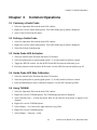
3.1 Centering a Guide Probe
1. Select the Operation Tab from the main GUI window.
2. Right click over the Guide Probe picture. The Guide Probe pop-up menu is displayed.
3. Select Center Probe from the menu.
3.2 Parking a Guide Probe
1. Select the Operation Tab from the main GUI window.
2. Right click over the Guide Probe picture. The Guide Probe pop-up menu is displayed.
3. Select Park Probe from the menu.
3.3 Guide Probe APD Activation
1. Select the Guide Probes Tab from the main GUI window.
2. Select the guide probe to operate (guide probe 1, 2 or both) with Link Selector control.
3. Toggle the APD HV control. See the APD HV and APD Overcurrent indicators go on.
4. Reset the protection with the Reset APD control. See the APD Overcurrent indicator go off.
3.4 Guide Probe APD Bias Calibration
1. Select the Guide Probes Tab from the main GUI window.
2. Select the guide probe to operate (guide probe 1, 2 or both) with Link Selector control.
3. Press the BIAS button to start a calibration sequence. See the RTC indicator go TBD.
3.5 Using TURSIM
1. Select the Operation Tab from the main GUI window.
2. Right click over the TURSIM picture. The TURSIM pop-up menu is displayed.
3. Select Injection Arm > In from the menu. Wait for the injection arm picture to appear in the
diagram.
4. Right click over the TURSIM picture.
5. Select Dimmer > On. Wait for the light indicator to go yellow.
6. Right click over the TURSIM picture.
7. Select Dimmer > Intensity > value.
21
ICSOFT User Manual 3.7.0, November 2013
Chapter: 3 Common Operations
8. Right click over the TURSIM picture.
9. Select Phase Screen [1|2] > In. Wait for the phase screen icon to move in.
10. Right click over the TURSIM picture.
11. Select Phase Screen > Speed > velocity. Wait for the velocity indicator to reach the desired
value.
3.6 Adjusting TURSIM light source
1. Select the WFS/ADC/TURSIM Tab from the main GUI window.
2. Use the [L|R|U|D] Offset Buttons (section Error: Reference source not found) to move the light
source while looking at the tilt residual (section 2.9).
3. Repeat until the tilt error is typically in the range [-0.1, 0.1]
3.7 Flattening the DM
1. Select the Operation Tab from the main GUI window.
2. Right click over the DM picture. The DM pop-up menu is displayed.
3. Select STATIC FLAT from the menu.
3.8 Flattening the DM taking rotation into account
1. Select the Operation Tab from the main GUI window.
2. Right click over the DM picture. The DM pop-up menu is displayed.
3. Select ROTFLAT from the menu.
3.9 Recording a new Flatten DM file
1. Close and open the loop on a suitable source. TURSIM will do.
2. Select the Operation Tab from the main GUI window.
3. Right click over the DM picture. The DM pop-up menu is displayed.
4. Select SAVE AS FLATTEN.
3.10 Resetting the WFS
1. Select the Operation Tab from the main GUI window.
2. Right click over the WFS picture. The WFS pop-up menu is displayed.
3. Select Reset WFS from the menu.
ICSOFT User Manual 3.7.0, November 2013
22
Chapter: 3 Common Operations
3.11 Tracking with the ADC
1. Select the Operation Tab from the main GUI window.
2. Right click over the ADC picture. The ADC pop-up menu is displayed.
3. Select In from the menu. Wait for the ADC icon to move in. The ADC state LED indicator
flashes indicating the motion is active.
4. Select the WFS/ADC/TURSIM Tab from the main GUI window.
5. Switch ON the ADC Compensation? Control.
3.12 Selecting the output port
1. Select the Operation Tab from the main GUI window.
2. Click on the Instrument selector box and select the instrument attached to the desired port.
3. Wait for the associated script to finish. The currently selected port is indicated by the Selector
Mirror indicator.
3.13 Selecting a Guider Star From a User Defined Catalog
1. Enter the name of the user catalog in the catalog input box, or use the browse button to select
the file.
2. Press the Load Catalog button to load the contents of the file into the guide stars table.
3. Click on the table line corresponding to the guide star candidate.
4. Press the Check [P1 | P2] button to make sure the coordinates of the guide star candidate are
within range of the current guide field. If the coordinates are not within range an information
message is showed at the Events & Commands list box.
5. Press Set [P1 |P2] to set the selected guide star coordinates as the target coordinates for the next
guide star acquisition. The coordinates are copied to the target [P1 | P2] indicators.
3.14 Selecting a Guide Star From the Yale Bright Star Catalog
The Yale Bright Star Catalog is available to peek a list of close by guide star candidates.
1. Select the radio button labeled “Yale Bright Star Catalog”
2. Select the source of the reference coordinates. Select “Telescope Coordinates” to use the current
RA/Dec coordinates of the telescope as informed by the TCS. Select “User Coordinates” to
manually enter the coordinates in the selected system (RA/Dec, Az/El, HA/Dec).
3. Press the “Closest Bright Stars” buttons. The guide stars table gets updated with a list of near by
stars.
4. Click on the table line corresponding to the guide star candidate.
5. Press the Check [P1 | P2] button to make sure the coordinates of the guide star candidate are
23
ICSOFT User Manual 3.7.0, November 2013
Chapter: 3 Common Operations
within range of the current guide field. If the coordinates are not within range an information
message is showed at the Events & Commands list box.
6. Press Set [P1 | P2] to set the selected guide star coordinates as the target coordinates for the next
guide star acquisition. The coordinates are copied to the target [P1 | P2] indicators.
3.15 Selecting a Guide Star Interactively Using GMAP
Guide star candidates can be interactively selected using the GMAP sky map. For details read the
GMAP User Manual.
3.15.1 NGS Mode
1. Point the telescope to the science field and put the natural guide star on the WFS. Use the WFS
acquisition camera to aid in that task.
2. If not already running GS3, this is a good time to launch the GS3 program either manually or
from the ICSOFT (Catalogs Tab).
3. Select the Skymap menu option from the File menu in the main GUI window. The skymap
windows shows up.
4. Press the Tel button in the sky-map window to grab the field coordinates. The window contents
get updated.
5. Press the PA button in the sky-map window to update the position angle. The window contents
get updated again.
6. Assuming that the natural guide star is now on the sky-map, right click on the star and press the
FC button to grab the offset between the mount and the center of the SAM field. The offsets are
sent automatically to the ICSOFT.
7. Press the Tel button in the sky-map window to refresh the screen and reflect the new field center
offsets.
8. Left click on a star inside the patrol field to select a guide star. A white circle around the star
signals that the star has been selected.
9. Press [P1|P2] button to send the coordinates of the selected star to the ICSOFT. The guide star
candidate coordinates are loaded into the target indicators in the Guide Probes Tab of the
ICSOFT main GUI window.
3.15.2 LGS Mode
1. Point the telescope to the science field and take a picture with SAMI.
2. “mscdisplay” the image. It is important to have the whole picture coordinates right. You can
check that by simply moving the cursor around and watch for the coordinates not resetting to
zero when changing detector.
3. Put the active focus on the SAMI GUI and press F3 to activate the interactive selection cursor.
ICSOFT User Manual 3.7.0, November 2013
24
Chapter: 3 Common Operations
4. Select a star by putting the cursor on top of a star and pressing “C”. The offset between the
SAM field center and the star is sent to the ICSOFT.
5. If not already running GS3, this is a good time to launch the GS3 program either manually or
from the ICSOFT (Catalogs Tab).
6. Select the Skymap menu option from the File menu in the main GUI window. The sky-map
windows shows up.
7. Press the Tel button in the sky-map window to grab the field coordinates. The window contents
get updated.
8. Press the PA button in the sky-map window to update the position angle. The window contents
get updated again.
9. Right click on the same star you just click on SAMI display and then press the FO button. This
will calculate the offset between the center of the field and mount coordinates taking into
account the offset reported by SAMI to the ICSOFT. The offset is sent automatically to the
ICSOFT.
10. Press the Tel button in the sky-map window to refresh the screen and reflect the new field center
offsets.
11. Left click on a star inside the patrol field to select a guide star. A white circle around the star
signals that the star has been selected.
12. Press [P1|P2] button to send the coordinates of the selected star to the ICSOFT. The guide star
candidate coordinates are loaded into the target indicators in the Guide Probes Tab of the
ICSOFT main GUI window.
25
ICSOFT User Manual 3.7.0, November 2013
Chapter: 3 Common Operations
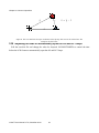
g
s
o = g − s
o
Figure 8: The cross mark the telescope coordinates in the sky-map. The circle is the selected star. The
triangle is the field center.
3.16 Adjusting the time to automatically open the AO and LLT loops
Edit the icsoft.ini file and change the value for keyword SLCHAUTOOPEN to control the time
before the LCH closure to automatically open the AO and LLT loops.
ICSOFT User Manual 3.7.0, November 2013
26
Chapter: 4 Configuration Files and Macros
Chapter: 4
Configuration Files and Macros
Configuration files provide a mean to set multiple system parameters to some predefined value.
Some of the parameters can be changed by the user during run-time, others will remain fixed and can
only be changed by editing the files and restarting the ICSOFT application. A detailed description of
the configuration files, macros, and their parameters follows.
icsoft.ini
instrument
.ini
telemetry
.ini
wfsfoc.ini
lltfoc.ini
sami.lua
stacklist.dat
faults.ini
soar
comms.ini
viserver.ini
hrcam.lua
btfi.lua
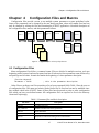
Figure 9: Configurationfiles and script dependencies
4.1 Configuration Files
Most configuration files follow a common format. Files are divided in multiple sections, each one
beginning with a keyword enclosed in square brackets. Each section lists a parameter name followed by
an equal sign and its value. A semicolon marks the beginning of a short parameter description.
[Section Keyword]
Parameter = Value
; this is the parameter description
Other files are ordinary text files containing a list of space separated fields. Table 1 lists the core set
of configuration files. The name and relative path of these files is fixed and can not be modified since
they arehard coded in the ICSOFT. Some of these files have keywords to point to other configuration
files which can have user defined names. All configuration files are expected to live in the directory
/home/ao/ICsoft/config.
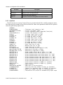
Table 1: Parameter files and their description.
File Name
Description
icsoft.ini
ICSOFT parameters
soar_comms.ini
SOAR communication library parameters
faults.ini
Faults definitions
instruments.ini
List of instruments and their location
lltfoc.ini
Polynomial coefficients relating focus to LGS distance.
27
ICSOFT User Manual 3.7.0, November 2013
Chapter: 4 Configuration Files and Macros
File Name
Description
rgatedelay.ini
Polynomial coefficients relating range gate delay to LGS distance.
telemetry.ini
Multiple sections describing test-point
viserver.ini
Labview remote panel definitions
wfsfoc.ini
Polynomial coefficients relating WFS focus and LGS distance.
4.1.1 icsoft.ini
The file has only one section: General. The user can hand edit this file to modify parameters values.
The following is an example of how this file looks like. Some of the parameters values will be replaced
when the application program exists.
[GENERAL]
FLENGTH=65666
INSTRUMENT=VISITOR
MODE=LGS
LGSDISTANCE=11.0
P1XUP=0
P1XDOWN=-50
P1YUP=50
P1YDOWN=-50
P2XUP=50
P2XDOWN=0
P2YUP=50
P2YDOWN=-50
SLOW=0.20
MEDIUM=0.30
FAST=10.00
LLTFLENGTH=1000
OBSLATITUDE=-30.238
OBSLONGITUDE=-70.734
OPOFFSETX=0.0
OPOFFSETY=0.0
GPOFFSETX=0.0
GPOFFSETY=0.0
GP1APDX=0.55
GP1APDY=0.10
GP2APDX=0.80
GP2APDY=0.30
SAMIFCX=1946
SAMIFCY=2077.6
SAMIROT=0
SAMISCALE=0.0453825
SLCHWINDOW=3600
SLCHRESET=1
SLCHSHUTLIM=5
SLCHAUTOOPEN=3
;
;
;
;
;
;
;
;
;
;
;
;
;
;
;
;
;
;
;
;
;
;
;
;
;
;
;
;
;
;
;
;
;
;
Telescope focal Length in [mm]
Current instrument label
Current operation mode [TSNGS,NGS,TSLGS,LGS]
Current LGS distance in [Km]
P1 stage right limit in [mm]
P1 stage left limit in [mm]
P1 stage up limit in [mm]
P1 stage down limit in [mm]
P2 stage right limit in [mm]
P2 stage left limit in [mm]
P2 stage up limit in [mm]
P2 stage down limit in [mm]
Short step size in [mm]
Medium step size in [mm]
Large step size in [mm]
Laser Telescope focal length in [mm]
Observatory Latitude in [deg]
Observatory Longitude in [deg]
Guide probes offset due to optics in x [mm]
Guide probes offset due to optics in y [mm]
Offset between mount and field-center in x [mm]
Offset between mount and field-center in y [mm]
Offset between encoder and quad sensor in x [mm]
Offset between encoder and quad sensor in y [mm]
Offset between encoder and quad sensor in x [mm]
Offset between encoder and quad sensor in y [mm]
Field center location in SAMI in x [pixels]
Field center location in SAMI in y [pixels]
SAMI rotation
SAMI scale in [arcsec/pixel]
SLCH override time window in units of [seconds]
Cadence for watchdog reset in SLGSOFT in [seconds]
Above this number the dome is considered open
Time before LCH closure to automatically open loops
ICSOFT User Manual 3.7.0, November 2013
28
Chapter: 4 Configuration Files and Macros
4.1.2 soar_comms.ini
The ICSOFT communication infrastructure is built upon the SOAR communication library (SCLN).
The SCLN is an implementation of a network communication layer that suites the interoperability
requirements of the SOAR telescope environment. Each section in the configuration file for this
software module defines a client-server pair with the corresponding listening port.
[CommLib]
Version=
[RTC]
IP_Server=
IP_Client=
IP_Port=
;Version for which this configuration is usable
;IP address of the server
;IP address of the client
;Remote port number
For more information on the SCLN and its protocol read the document “SOAR Communication
Library New” available at the SAM web site archive.
4.1.3 viserver.ini
The ICSOFT uses Labview remote panels to display some interfaces and charts. The remote panel
technology allows to open a GUI located in another computer as it has been opened locally. The
viserver.ini file includes multiple sections with information regarding the name and location of the
remote GUI. The ICSOFT invokes the remote panel using the section labels in this file.
[NAME]
VINAME=
ADDRESS=
PORT=
;
;
;
;
unique label identifying the remote panel.
name of the remote VI of the GUI
remote machine IP address
remote machine listening port
4.1.4 telemetry.ini
The ICSOFT use the telemetry.ini file to format the telemetry test-points and figure out the sampling
period for logging telemetry data. The file includes multiple sections, each one corresponding to a
different test-point. The ICSOFT hard wires the ID to the test-point to link it to a section.
[TESPOINT NUMBER]
ID=
Label=
Units=
Help=
Stime=
Min=
Max=
;
;
;
;
;
;
;
;
unique number for this section
unique number used as the test-point ID
string test-point name
test-point measurement units
brief test-point description
sampling time in [seconds]
minimum legal value for the test-point
maximum legal value for the test-point
The ICSOFT will save every Stime seconds the test-point value to the ICSOFT log file. The Label
and Units keyword will be used to format the telemetry table and charts (see section 2.20 above).
4.1.5 instruments.ini
The instrument.ini file is used to populate the Instrument Selector Box Control (see section 2.15
above). It include multiple sections, one for each instrument defining a label and a configuration macro.
29
ICSOFT User Manual 3.7.0, November 2013
Chapter: 4 Configuration Files and Macros
Right now the configuration macro selects the right FOLD2 mirror position for the instrument.
[INTRUMENT NUMBER]
ID=
Name=
Macro=
;
;
;
;
unique number for this section
unique number uses as the instrument ID
text string with the instrument name
instrument macro to configure SAM
For example, to add SAMI to the instrument.ini file edit the file defining an ID, then Name=”SAMI”
as the name, and finally Macro=sami.mc as the initialization macro.
4.1.6 lltfoc.ini
This is TBD but after conversations with RT he most probably will gave me a polynomial fit to the
function relating LGS distance in [Km] to LLT focus position in [mm]. The lltfoc.ini file includes a
single section with the coefficients of a 9th order polynomial. To use a lower order just set the upper
order coefficients to zero.
[GENERAL]
a0=2.0
a1=2.0
a2=0.0
a3=0.0
a4=0.0
a5=0.0
a6=0.0
a7=0.0
a8=0.0
a9=0.0
4.1.7 rgatedelay.ini
This is TBD but probably a polynomial fit will be used to relate the LGS distance in [Km] to the
range gate delay in [ns]. The rgatedelay.ini file includes a single section with the coefficients of a 9th
order polynomial. To use a lower order just set the upper order coefficients to zero.
[GENERAL]
a0=2.0
a1=2.0
a2=0.0
a3=0.0
a4=0.0
a5=0.0
a6=0.0
a7=0.0
a8=0.0
a9=0.0
4.1.8 wfsfoc.ini
This is TBD but after conversations with RT he most probably will gave me a polynomial fit to the
function relating LGS distance in [Km] to WFS focus position in [mm]. The wfsfoc.ini file includes two
sections; the GENERAL section includes the coefficients of a 9th order polynomial for the fit. To use a
lower order just set the upper order coefficients to zero.
ICSOFT User Manual 3.7.0, November 2013
30
Chapter: 4 Configuration Files and Macros
For example, the section labeled NGS, set the nominal WFS position in [mm] when under NGS and
TSNGS operation modes.
[GENERAL]
a0=2.0
a1=2.0
a2=0.0
a3=0.0
a4=0.0
a5=0.0
a6=0.0
a7=0.0
a8=0.0
a9=0.0
[NGS]
FOCUS= ; WFS focus under NGS mode in [mm]
4.1.9 Dmflat_rot1.txt
Text file containing the coefficients to adjust the flat DM voltages. The file is 60 lines long and each
line correspond to DM actuator line-number. Each line in turn contains three coefficient to calculate the
actuator voltage as
Voltate = P0 P1 cos ROT P2 sin ROT
(1)
Where ROT is the current Nasmyth rotator angle.
4.1.10 faults.ini
The ICSOFT logging and error handling infrastructure is built upon the FaultsLib software module.
The configuration file for that module defines error codes and their corresponding error messages.
[0]
ID=
What=
Help=
Limit=
LogAlways=
;Fault identification number
;The fault label
;Brief description of the fault
;Number of occurrences to raise an alarm
;TRUE or FALSE.
The error code assignment to a certain fault condition is hard coded in the software and the
configuration file makes possible to hand edit the error message content. If the Limit keyword is set
to -1, then fault condition gets ignored. If the LogAlways keyword is set to TRUE, then the event will
be logged independent of if there was an error or not.
4.2 Macros
The ICSOFT executes an initialization macro when it first starts. The macro is the AO software
initialization macro initics.mc. This macro is the last initialization done by the AO software before it
enters operational mode. So it is the appropriate place to set parameters or override some default
parameter values. Right now the initics.mc macro is empty.
31
ICSOFT User Manual 3.7.0, November 2013
Chapter: 4 Configuration Files and Macros
4.3 Scripts
4.3.1 Coded Names
4.3.2 Instrument Initialization Scripts
For each instrument to be used with SAM and initialization script is provided. The script name is
defined in the instrument.ini file and it is executed when an instrument gets selected using the
Instrument Selector Box (see section 2.15 above). Typically, this script will command the output
selector mirror to move to the position that will feed light to the instrument and will adjust the WFS
focus position if needed. An example follows depicting SAMI, the dedicated science CCD
% cat ICsoft/scripts/sami.lua
sam.command("LOG SAMI setup...")
-- Adjust WFS focus
sam.command("LOG Adjusting WFS focus")
sam.wait_until_end("AOM WFS FOCUS MOVE 80.3",15000)
-- Select SAMI port
sam.command("LOG Moving Output Selector Mirror Out")
sam.wait_until_end("AOM OUTSEL MOVE OUT",15000)
sam.command("LOG SAMI setup done")
Other commands can be included here as needed.
4.3.3 User defined scripts
User defined scripts should be placed in the ICsoft/scripts directory. They will be automatically
displayed in the scripts list box in the Operation Tab (see section 2.15.1 above).
ICSOFT User Manual 3.7.0, November 2013
32
Chapter: 5 Log Files
Chapter: 5
Log Files
When the ICSOFT first runs, it opens a regular text file to save log messages describing run-time
events. Events can be of several types including type alarm, type command, type status, and type
simple-event. For details on the implementation of the logging mechanism read the ICSPM.
The events and the conditions in which a log message is generated is hard-coded into the ICSOFT,
but certain flexibility exists when it comes to define error messages associated to error codes. A
configuration file called faults.ini (section 4.1.10 above) exists that serves as a look up table between
error codes and error messages. The logging engine, when given an error code, searches the right error
message and then produces the corresponding log message.
The actual log file can be found under directory /home/ao/ICsoft/logs which is typically a link to a
user defined directory. Each line in the log file starts with a time-stamp that includes date and time in
YYMMDD HH:MM:SS format. Then a label describes what type of event (alarm, status, etc.) the log
message refers to. A second label states the name of the “originator”, that is, the piece of software code
that produced the event. This second label is most useful for debug purposes. The line ends with the log
message describing the event. This last message does not follow a predefined format.
We use the system utility log rotate to manage the ICS log file. The configuration file is in
/etc/logrotate.d/icsoft.
% cat /etc/logrotate.d/icsoft
/home/ao/ICsoft/logs/*.log {
compress
daily
rotate 30
}
The above keeps the last thirty days logs in compressed format. The logrotate utility is executed
as a crontab job by the cron daemon on a daily basis (see /etc/cron.daily/ directory for logrotate).
We adjusted it to run at midday
% cat /etc/crontab
# run parts
01 * * * * root run_parts /etc/cron.hourly
00 12 * * * root run_parts /etc/cron.daily
22 12 * * 0 root run_parts /etc/cron.weekly
42 12 1 * * root run_parts /etc/cron.monthly
Note: The whatis database update has to be removed!!
5.1 Type Alarm Events
Events of type alarm produced by the ICSOFT can trigger the alarm flag. Each error code defined in
the faults.ini configuration file has an associated counter that keeps track of consecutive type alarm
events. When three alarm messages in a row for a given error code are detected, the global alarm flag is
33
ICSOFT User Manual 3.7.0, November 2013
Chapter: 5 Log Files
raised. The number of type alarm events in a row is actually configurable in the faults.ini configuration
file (see section 4.1.10 above).
ICSOFT User Manual 3.7.0, November 2013
34
Chapter: 6 Acquisition Camera Software
Chapter: 6
Acquisition Camera Software
6.1 User Interface
6.1.1 Main GUI
6.1.2 Image Display
6.1.2.1 Cross-Hair
A green cross-hair is available for helping defining a reference position (e.g. field stop position in
NGS mode and laser guide star in LGS mode).
When the program first starts the last stored position is used to draw the cross-hair. Left clicking in
the image display moves the cross-hair to the cursor position. Options for controlling the cross-hair
attributes are available via a pop-up menu.
6.1.2.2 Pop-Up Menu
By right-clicking in the image display area a pop-up menu is opened. The available options are
described below
Save to Disk. Use this option to save a snapshot to disk in FITS file format.
Force Mono.
Scale.
Lock Cross-Hair. When the cross-hair is locked left clicking in the image display does not
change its position.
Show Cross-Hair. Toggles between showing and hiding the cross-hair.
Cross-Hair Set. Record the current cross-hair position. The coordinates get saved to the
configuration file acqcam.ini.
Cross-Hair Recall. Re-position the cross-hair to the last recorded position. The software reads
the coordinates stored in the configuration file acqcam.ini.
Zoom Factor [10%-100%].
6.2 Configuration File
A single configuration file acqcam.ini is available. The file is in sub-directory bin-pc/x86/ under
directory /home/ao/Prosilica_GigE_SDK/.
[CROSS-HAIR]
XPOS=
YPOS=
35
ICSOFT User Manual 3.7.0, November 2013
Chapter: 7 Troubleshooting
Chapter: 7
Troubleshooting
7.1 Can't Find Guide Stars
7.1.1 NGS Mode
1. Check using the WFS Acquisition Camera that the natural guide star is in the WFS sensor.
2. Check using GMAP that the natural guide star is in the center of the field. If not use the FC
button to correct the field center offsets. Remember to press Tel to refresh the screen.
7.2 Tweaking Quad-Sensor Offsets
1. Lock the star using M3 and then manually move the guide probe making M3 follow until you
get the natural guide star right in the WFS.
2. Record the guide probe position
3. Now acquire the guide star using the Acquire GS button and record the guide probe position.
4. Subtract the recorded values to obtain the amount to add to the current quad-sensor offsets
5. Hand edit the icsoft.ini file to enter the new values.
6. Re-start the application to grab the new values.
37
ICSOFT User Manual 3.7.0, November 2013
Chapter: 8 Glossary
Chapter: 8
Glossary
AO
Adaptive Optics.
DM
Deformable Mirror.
DSP
Digital Signal Processing.
DAQ
Data Acquisition.
Effective Compensation
Maximum order compensation for a given reconstructor matrix.
FITS
Flexible Image Transport Format.
FWHM
Full Width at Half Max.
GLC
Ground Layer Compensation
G Matrix
Slopes in x and y are related to aberrations by the gradient matrix G.
G* Matrix
Inverse of the gradient matrix G.
H Matrix
Interaction matrix.
H* Matrix
Reconstructor matrix.
ICSOFT
Instrument Control Software. Supervisory control application that
handles the business logic of the SAM instrument.
Integrator
Digital controller. Measured residuals are added to the previous signal
with some gain.
Interaction Matrix
The relation between the WFS and the DM in an AO system is
characterized by the interaction matrix H.
Kolmogorov Law
The Kolmogorov model of the turbulence distortions prescribes the
specific form of the phase structure function for the optical wave.
LGS
Laser Guide Star
LLT
Laser Launch Telescope
Modal Coefficients
Zernike mode coefficients
Modal Reconstructor
Error signal delivered by the WFS is converted into modal amplitudes
by matrix G*. Amplitudes are weighted and transformed to voltages by
ICSOFT User Manual 3.7.0, November 2013
38
Chapter: 8 Glossary
matrix P*.
NGS
Natural Guide Star
Noise Propagation
Noise propagation is described by the covariancematrix of Zernike
noise coefficients.
Optimal G* Reconstructor
Optimal modal reconstructor. Takes into account the information on the
statistics of the input disturbance contained in the Noll covariance
matrix, and correlated centroid noise.
P Matrix
Aberrations are related to DM voltages by the projection matrix P.
P* Matrix
Inverse of the protection matrix P.
PXI
modular instrumentation standard based on CompactPCI developed by
National Instruments with enhancements for instrumentation
Reconstructor Matrix
Inverse of the interaction matrix H.
Regularization Parameter
Setting this parameter > 0 helps balancing the noise and input signal in
case when the noise is strong. The reconstructor with the right choice
of this parameter gives the smallest RMS wavefront error.
RTC
Real Time Computer
RTCORE
Real Time Core
RTSOFT
Real Time Software
RTSPM
Real Time Software Programmer Manual
SAM
SOAR Adaptive Module
Slope
Gradient averaged within the sub-aperture and expressed in units of
phase difference between the edges of sub-aperture.
Smith Predictor
Digital controller that counter acts the effect of delay in the loop.
SVD
Singular Value Decomposition
SVD Reconstructor
The interaction matrix is inverted using SVD. Singular values below
some threshold are set to zero.
TTP
Tip Tilt Probe
TURSIM
Turbulence Simulator
39
ICSOFT User Manual 3.7.0, November 2013
Chapter: 8 Glossary
WFS
Wavefront Sensor
WCoG Method
Weighted Center of Gravity. Improved center of gravity with different
weight to each pixel depending on their flux.
Zernike Coefficients
Input disturbance, correction and residuals are represented as
coefficients of Zernike modes.
ICSOFT User Manual 3.7.0, November 2013
40