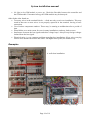
1
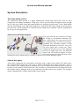
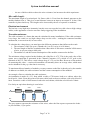
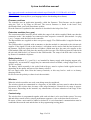
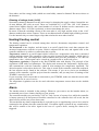
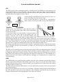
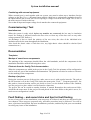
System installation manual
Installation Guide
Page 1 of 19
System installation manual
Table of contents
Table of contents
Table of contents
Preface – The intensions of this manual.
Disclaimer – when to contact us:
The manual.
System Description:
The smart-house system:
Smart-house principle diagram
Cable & bus signal:
Example of installation topologies:
Cable types:
Electrical environment
The cable resistance
Cable colors:
Installation
Things to consider when you are using the alarm:
Placing of components:
Placing of extension modules:
Cabinet build-up, terminal blocks etc.:
Connections in cabinets and wall/ceiling boxes:
Detailed connection diagrams:
i
Battery back-up
ii
Code Keypad
iii
1-10V control with external modules (power dimmers etc.)
iv
Heating control with SSR’s & Solenoid valves incl. power supply
v
Bus separator
vi
Wireless base unit
vii GSM Modem
Coding of modules
The use of the address coding unit ‘BGP-COD-BAT’ or ‘GAP1605’
The Controller
Electrical connection
Communication
Config Tool (also known as the Tool)
Firmware revisions
Extension modules (bus, gsm)
Battery backup
Wireless
Comissioning
Battery life
Light control
PIR (Passive Infrared Detector) usage
Dimming of energy loads
Page 2 of 19
1
2
4
4
4
5
5
5
5
6
6
7
7
8
9
9
9
9
9
9
9
9
9
10
10
10
10
10
10
10
11
11
11
11
12
12
12
12
12
13
13
13
13
System installation manual
Dimming of voltage loads (1-10V)
Heating/Cooling control
Alarm
PIR
GSM
Combining with external equipment
Commissioning / Test
Insulation test
Documentation
Templates
Markup of smart-house components
Printouts from the Config Tool documentation
Backup of projects
Fault finding – and some tricks and tips for fault finding
Search tree
What can be measured
Megger (Isolation tester)
Cable faults
Coding errors
Typical errors
Examples
Appendix A.
Local rules and regulations
Page 3 of 19
14
14
14
15
15
16
16
16
16
16
16
16
16
16
17
17
17
17
17
17
18
19
19
System installation manual
Preface – The intensions of this manual.
This manual is intended for the persons that are to design, install and/or make changes of a smarthouse installation (hereafter called ’Bus’). These persons can be installers and system integrators,
and other persons who are involved in the task of servicing the Bus.
When you have read this manual carefully, you will be aware of what to do, and also what not to
do, which also is an important knowledge.
Disclaimer – when to contact us:
With this manual you have a tool that gives you the knowledge of how to make a good installation
of our Bus. If you experience any problem with your installation after having read this manual, even
when you have followed all the stated advices, you are welcome to contact our sales supporters.
The manual.
The manual is divided in two parts, the first part is the general description for the Bus, the second
part is dealing with country-specific details, such as public regulations, deviations in cable
specifications and insulation etc.
Page 4 of 19
System installation manual
System Description:
The smart-house system:
The smart-house Bus system is a signal transmission system that reduces the need of wires
compared to an ordinary installation. Using only 2 wires, up to 256 different signals can be brought
up to 10 km away. Many input and output modules are supplied from the same 2 wires. Both digital
(on-off) and analogue (e.g. temperature, light level, wind speed and other) signals can be present at
the same time. All the functions are controlled by the smart-house controller, which is programmed
by an easy-to-learn application.
Smart-house principle diagram
The goal with any bus system is to reduce
the wiring to an absolute minimum. We
have achieved this by using two wires for
the communication. As seen in the figure,
signaling four individual signals in both
directions demands at least five wires, one
for each signal, and a return wire. These
signals are carried over two wires, allowing
not only 4 signals, but up to 128 different
inputs and 128 different outputs on these
two wires at the same time. Because of the
construction, these signals may be a mixture of digital (on-off) and analogue signals.
Cable & bus signal:
All our Bus components are connected to each other with a single 2-wire cable. This cable carries
the communication signal that comes from a central component, the Channel Generator. These 2
wires carries a low-voltage signal, a pulsating DC of 8,2V, and therefore attention must be paid to
keep the correct polarity of the connection. Also, the Bus is overload and short-circuit protected, but
the modules may be damaged if they are connected to the Bus with reverse polarity. The modules
cannot withstand other voltages than the Bus signal voltage.
Page 5 of 19
System installation manual
Example of installation topologies:
Straight-through
Star
Ring
A combination of the above
As seen in the topology examples, the type selected is not critical, and may be combined as one
likes.
Cable types:
The cable to be used for the Bus signal is generally non-critical, but some specifications must be
fulfilled:
Do not:
-
connect any of the wires to other voltage potentials.
connect any of the wires to protective earth (PE).
parallel any wires to increase the square of the cores.
use larger cable gauges than 2.5 mm2 (AWG 13).
put different sized wires in the same screw terminal.
We recommend you to:
-
use 1.5 mm2 conductor size, twisted pair cable.
use single core cable in non-cabinet mounted modules.
use ferules on multi-core wires.
use shielded cables in high-noise (electrical) environments only.
Be aware of:
-
that the use of shielded cables reduces the total overall length of the cable.
Page 6 of 19
System installation manual
-
the use of thicker cables reduces the wire resistance, but increases the cable capacitance.
Max cable length:
The maximum length of a twisted-pair 2x1.5mm2 cable is 5 km from the channel generator to the
module furthest from it. This gives a total distance between an input to an output of 10 km, if the
controller is placed mid-way. This length can be increased by the use of repeaters or modems.
Electrical environment
The bus has a very high noise immunity, but take care not to put the bus cable close to high voltage
cables, as the appearance of noise can cause faulty triggering of the installation.
The cable resistance
The cable resistance is a factor that must be calculated in many installations. If the cable resistance
is too large, the result is a too high voltage drop over the wires – making the connected modules
malfunction, or not work at all, in worst cases.
To calculate the voltage drop, you must know the different parameters that influct on the result:
1. The resistance of the wire pr.m. (Thumb-rule: 1m of Cu-wire is 0.019 ohms)
2. The total length of the Bus (remember that a Bus cable of 500 meters contains 2x500 meters
of wire, as you are using a cable pair).
3. The number of, and the current consumption of the modules connected to the Bus.
The minimum voltage required at the furthest end of the Bus is 4.7V. This is the peak value of the
square wave signal that is generated in the Channel Generator (CG), which is 8.2V peak at the
terminals of the CG: This leaves a total voltage drop of 3.5V over the Bus. Be aware of the method
of measuring this value – a universal instrument will normally show an average value, which must
not be mistaken for the p-p value that is necessary.
To maximum allowed number of modules you may connect on the Bus is thereby set by the number
of addresses available, the cable resistance and the current consumption of the modules.
An example of how to calculate the cable resistance:
An installation is made of a CG, from which a cable of 750 meters leads to a cabinet, where the
local load is 11mA. From this point a 500 meter cable leads to the next cabinet, with a local load of
8mA. From this a cable of 1000 meters leads to the end cabinet, which has a local load of 14mA.
For clarity an equivalent drawing is seen below:
RLoad1
1000m
RCable2
RCable3
RLoad3
RCable1
Bus +
500m
RLoad2
750m
Bus -
The grey squares represent the resistance of the wires, where the blue squares represent the loads –
or your modules, if you prefer.
Page 7 of 19
System installation manual
The example continues:
The current flowing through the first part of the cable – Rcable1 – is the sum of all currents: 11mA
+ 8mA + 14mA=33mA, called ‘IRCable1’.
The rest can be calculated:
IRCable2= IRLoad2 + IRLoad3 = 8mA + 14mA = 22mA.
IRCable3= IRLoad3 = 14mA.
The voltage drop over the 3 parts will then be:
RCable1= 2x750x0.019=28.5 ohms. Then 28.5 ohms x 33mA = 0.94V
RCable2= 2x500x0.019=19 ohms. Then 19 ohms x 22mA = 0.42V
RCable3=2x1000x0.019=38 ohms. Here the drop is 38 ohms x 14mA = 0.53V
The voltage on RLoad1 is 8.2-0.94=7.26V
The voltage on RLoad2 is 7.26-0.42=6.84V
Finally, the voltage on RLoad3 is 6.84-0.53=6.31V
In this example, the voltage on all modules will be sufficient. It is also assumed that the CG used is
able to deliver the required current for all modules.
Cable colors:
The cable colors has no effect in the functionality of the installation, but by using specific colors for
the Bus wires, the installation will be clearer.
Page 8 of 19
System installation manual
Installation
When you install the components, some rules must be followed. Read the data sheets carefully, so
you can determine the heat and power dissipation of the modules. Some of the modules must be
placed accordingly to the cabling between the modules, read more in the chapter ‘Placing of the
components’ later.
Things to consider when you are using the alarm:
When you are preparing the installation wit the alarm components, we recommend that all the
signals that are to be monitored are placed on the bus of the controller, and not on the extension
modules. The reason is that the extension modules are AC powered only, and if they lose power, no
signals will be fed back to the controller.
Placing of components:
The placing of the cabinet components are non-critical, but bear in mind that a simple, logic way of
mounting results in an easy expansion of the system, or in a fault-finding situation. The other
components (non-cabinet) are, of course, mounted following the regulations of the countryspecifications.
Placing of extension modules:
The extension modules are connected to the controller via some special cables that comes in
maximum lengths of 250mm. These cables must not be extended. This requires some thinking, as
the modules must be placed beside each other, or in a way so the cables can be mounted securely.
Cabinet build-up, terminal blocks etc.:
There are no specific rules to consider regarding the cabinet layout. Although the cable connections
between the controller and GSM and between the controller to the (up to) 3 extension modules must
be considered. See the pictures in the last paragraphs for some details of a good installation.
Connections in cabinets and wall/ceiling boxes:
See to that the wires that goes into the terminals have the same dimensions, and that the number
doesn’t exceed the max. limitations. Use standard installation rules, but check the addendum
regarding your local rules and regulations.
Detailed connection diagrams:
You may find some useful information about how to install the components in some special
situations in the following paragraphs:
i Battery back-up
When you are using an external battery as a backup supply for the controller, some points must
be noted: The controller can only charge the battery when it’s on normal AC supply. The
charging current is limited to the charging of the battery. No other DC supplied parts should be
supplied from the backup battery.
ii Code Keypad
The code keypad (BACC-KEYPAD-DC) needs an external 12 VDC supply. The charging
circuitry for the backup battery of the controller is not dimensioned to supply the keypad, and
Page 9 of 19
System installation manual
should not be used as a supply for it. In order to program the keyboard, you may need to
disconnect it from its 12V power supply, so have this in mind when you make the installation.
iii 1-10V control with external modules (power dimmers etc.)
The 1-10V module (BH4-D10V2-230) can be used to control third party output modules, e.g.
power modules for lights, and this needs some attention. The output equals a resistor, so no
voltage is delivered from the module. When adjusted to 0%, the voltage across the resistor is 1
V, and the corresponding relay is off. This means that the light of a ballast, e.g. for neon bulbs,
is not fully off. To have the lights switched all off, use the relay contact to switch off the load.
Read the data of the relay and the load, and pay good attention to the max. limits, so the contacts
does not burn because of an overload.
iv Heating control with SSR’s & Solenoid valves incl. power supply
The controller has a built-in temperature regulating function, and to control the electric
solenoids the SSR output modules are recommended.
v Bus separator
When the bus must be secured against short-circuits, the bus separator can be used. The unit
isolates the signal on the secondary side from the primary bus, so the primary part of the
installation functions normally, even when the secondary is short-circuited. The mounting is
straightforward, but pay attention to the max. load of the module.
vi Wireless base unit
The physical mounting of the wireless base requires some thoughts about the physical placing.
Remember that the radio waves must be passed both ways between the base and the transmitters
and receivers. Any element that is ‘in the way’ of the waves will reduce the radio waves.
Different material reduces by different factors.
vii GSM Modem
Be aware of that the cable must me mounted correctly! A wrong mounted cable will result in a
damaged module. The modem is supplied from the controller, and needs no other cable
connection, except from the antenna. The modem responds by some different blinking pattern of
the yellow LED in the front. The PIN of the SIM-card must be set prior to the use in the modem.
Refer to the data sheet to achieve information.
Coding of modules
When the module overview is complete, regardless of if it is created manually or automatically, this
list is used as the reference to program the addresses of the different modules.
The use of the address coding unit ‘BGP-COD-BAT’ or ‘GAP1605’
All the modules used are programmed with either one of the above named address programmers.
Refer to the user manual of the unit in order to see the full functionality of it.
Page 10 of 19
System installation manual
The Controller
The controller (BH8-CTRLX-230) is supplied with a protective transparent plastic film covering the
ventilation slots. The film protects the inside vital parts of the unit from conducting material to enter
the housing. Before supply is applied, the film must be removed. The ventilation slots must not be
covered when power supply is applied to the unit.
Do not over-tighten the screw terminals.
We recommend you to bring a router with DHCP facility, patch cables, an SD-card (max 2GB) and
a card reader/writer when you will service a smart-house installation.
Electrical connection
Always check that the polarity of the Bus wires is correct.
If a battery is to be connected to the battery terminal, check that the polarity is correct before it is
connected.
The power supply terminals are for AC voltages, so the polarity is of no matter.
Communication
The controller can communicate in two ways, either via the front-mounted Ethernet connection, or
via rs-232, which connects to 3 screw-terminals.
The Ethernet communication carries both real-time information of the project that is currently
running, and is also used for the setup program, the Configuration Tool.
The rs-232 carries only real-time information of the program.
To configure the controller with a new project, or to alter an existing project, the controller must be
connected to a PC running a Windows OS. The physical connection can be done either via a router
(recommended), or through a patch cable between the PC’s Ethernet plug and the controllers’
Ethernet plug. (Requires specific settings in the PC – this is recommended for skilled personnel
only).
The project can also be transferred to the controller by the use of an SD-card. See the Config Tool
help to see how this is done.
Config Tool (also known as the Tool)
To configure the controller, you need the Config Tool that is supplied with the controller.
Visit your local smart-house website to download the latest version of the Tool. The tool is free of
charge, and fully functional.
During the installation, a Windows firewall warning may appear, be sure to accept the setting
change.
We recommend the user of the program to attend a training course, in order to achieve the necessary
knowledge of the functionality of the controller.
The projects can be written while you are off-line of the controller.
The Config Tool requires some OS files necessary for it to run. These are: Windows Mobile
Device, which can be downloaded at:
http://www.microsoft.com/downloads/en/details.aspx?displaylang=en&FamilyID=46f72df1-e46a4a5f-a791-09f07aaa1914#Top
(Select your language before downloading the software)
and dotNET framework 2.5 or newer found at:
Page 11 of 19
System installation manual
http://www.microsoft.com/downloads/en/details.aspx?FamilyID=333325fd-ae52-4e35-b531508d977d32a6
(The version 3.5 shown)(Select your language before downloading the software)
Firmware revisions
The controller runs an application internally, called the firmware. This firmware can be updated
using the Tool, or by using an SD-card. The newest firmware is found in the latest Tool,
downloaded from your local smart-house website.
How the firmware is updated in the controller is described in the help of the Tool.
Extension modules (bus, gsm)
The extension modules must be placed within the range of the cables supplied. Make sure that the
connection to the 3 bus modules are connected to their respective connector. (Bus module 1 to plug
1 etc.). Compare with the label on the controller.
The Bus modules are supplied to their own power supply. The GSM module is supplied from the
controller.
The GSM module is supplied with an antenna, so that the module is connected to the relevant tele
supplier. If the signal is weak on the location, a cell-phone can be used to find the best location for
the antenna. Check the signal with the cell-phone (which must have the same tele supplier as the
GSM module SIM-card), and place the antenna on the best spot. The SIM-card must be coded with
the pin-code 9090 before it is inserted in the GSM module. The setup of the PIN-code is also done
by means of a standard cell-phone.
Battery backup
The battery terminals 35 (+) and 36 (-) are intended for battery supply with charging support only.
Alternatively, an external DC supply may be connected to these terminals, voltage range from 12 to
14VDC accepted.
The battery, which normally is the sealed lead-acid type, must be replaced with regular intervals,
depending on the quality and specs of the battery selected.
Do not supply other units from the battery terminals, as this may lead to weak or no battery
charging current.
Do not reverse the polarity or short-circuit the terminals.
Wireless
When the wireless modules are used, some things must be considered.
The wireless signals are transmitted at a frequency of 868 MHz, and care must be taken about the
placement of the wireless base, because of the range limitations. Normal free-air range is approx.
100 meters. Depending on the material, any obstructions will cause reduction of the range of the
radio waves.
Comissioning
The wireless base is programmed together with each unit that is to be used in the system. You may
add and delete remote units by simple push-button sequences, refer to the data sheets on how-to.
Be aware of that a unit cannot be added or deleted if it is not functional, communication must be
established between the unit and the base in the programming/erasing phase.
Page 12 of 19
System installation manual
Battery life
Because the wireless units are battery powered, some action should be taken to make regular
intervals of changing the batteries.
Light control
When the light functions are used in the building, many automated processes may be presented for
the user. An advise is to let the customer be a part of the planning process, so he decides what to
control, and how it is controlled. If many automation processes are available in certain push-button
combinations, these may not be logically for the customer to use, or even remember where they are
placed.
PIR (Passive Infrared Detector) usage
When a motion detector, or PIR, is used to switch the light, see to that it is placed where it can see
the person, but also so it doesn’t see other heat movements that can occur. The PIR will see any
heat movements, and the colder the environment, the easier it detects the elements. The PIR detects
heat motion across its visible range, but not along its range. This means, if the PIR is placed e.g. in
the end of a long hallway, it may not detect a person that is approaching the PIR, or moving away
from the PIR. Then an alternative placement is necessary.
Do not place the PIR where it faces heat sources like ovens, spot lights, moving lights etc., as this
will trigger the PIR signal.
Dimming of energy loads
The use of light dimmers becomes more and more popular, due to the cost saving, but also the scene
effect that comes with the dimmed light.
The dimmer controls two types of loads, either regular transformer load (iron-core), or switch-mode
(electronic) transformer load. When an ordinary filament bulb is used, the dimmers are set to
transformer load.
Take care of the load capability, as the data states the load at the output terminals. If a direct
filament bulb is used, you can put the full lamp load on the output. If a low-voltage bulb is supplied
from the transformer that is connected to the output, the thumb-rule calculation is 70% to the bulb,
and 30% to the transformer. This means if your dimmer is capable of controlling up to 230W, 30%
of this load goes to the transformer – this equals 69 watts – only 161 watts is available for the bulbs.
This equals a maximum of eight 20W filament bulbs on one transformer output. If a total bulb load
of more than 161 watts is connected to the transformer, the dimmer will be overloaded.
When an electronic transformer is used, the ratio is 10% / 90%, so it has a higher efficiency. In the
above example, 23 watts goes to the electronic transformer, and 207 watts is available for the bulbs.
That equals ten 20W filament bulbs.
Another consideration is the wire length from the transformers to the bulbs. When an ordinary
transformer is used, the wire from the transformer to the bulb is to be kept short because of the
power loss in the cables. In the case of an electronic transformer, the cables must be kept short for
the power loss in the cable, but also for the noise introduced on the cable.
Some LED lamps can also be dimmed, if they are designed to be used with dimmers with phaseangle regulation. This is normally stated in the documentation of the bulb. The behavior of the light
can be quite different from one LED type to another, so care must be taken to select a type that
gives the wanted dimming effect.
Do not use LED’s that are not intended for dimming on the dimmers.
Page 13 of 19
System installation manual
Neon tubes, and low energy bulbs (which are neon bulbs), cannot be dimmed. Do not use these on
the dimmers.
Dimming of voltage loads (1-10V)
Neon tubes cannot be dimmed over the entire range by changing the supply voltage. Instead the use
of neon ballasts (HF coils) are used. These are controlled on a 1-10V line. Our 1-10V dimmers
control these ballasts directly, and a total number of at least 50 ballasts can be connected to one
dimmer output. The 1-10V line is polarized, so do not interchange the wires.
Be aware of that the switching current of the neon tubes is very high, and the relays in the 1-10V
dimmer modules have micro contacts. These are not dimensioned to handle high switching currents.
Use the internal relay to control larger relays that switches the neon tubes instead.
Heating/Cooling control
The heating control can be selected among three choices: thermostat, temperature control, and
temperature regulation.
The thermostat is the simplest, and the input is an on/off signal from a unit that compares the
measured temperature with the set point, which is adjusted on the unit, and signals back to the
controller whether it is colder or warmer than the set point.
Temperature control is an on/off signal which is based on a temperature value that is measured
with an analogue sensor. The parameters of the set point is treated in the controller, which again is
configured in the Tool. The temperature control function also gives the possibility to ‘see’ the real
temperature value – which again can be viewed on a touch-screen or in the web-server.
Temperature regulation is targeted to the Bxx-TEMDIS units with display. The principle of the
regulation is PID with fixed parameters. The display unit measures the temperature, displays this,
and communicates with the controller, which in term manages the temperature regulation. The
desired setpoint is selected on the device. This value is stored in the controller, and when read-back,
the last setpoint can be found in the software. This means, if you are to service an installation,
connect to the controller, read the project from the controller, and you may have all settings of the
TEMDIS’s stored on your PC.
If you are using a floor sensor that is connected to your TEMDIS, make sure that the sensor cable
can be pulled out, in case of service.
The temperature regulation can also be used with other temperature sensors that use the Analink
protocol.
Alarm
The intruder alarm is included in the package. Whenever you want to use the intruder alarm, we
recommend you to have a battery backup on your system.
The extension modules are powered by 230V AC only. In case of a power loss, while the controller
is battery-powered, all bus-powered modules connected to the controller bus will work, but the
other bus(ses) will be in a power-down state.
This means that any alarm component that is expected to give a signal during a power loss, must be
connected to the primary bus (the controller bus). If an alarm signal is placed on any extension bus,
this will be treated as an active signal in the case of a power down, causing the alarm to be
triggered.
Page 14 of 19
System installation manual
PIR
The PIR’s used as alarm components must be carefully placed. The PIR detects a movement of an
object that is warmer as the background, if the movement is within the range, and also within the
sensing field of the lens system. An object that moves across the sensing field is detected better as
an object that moves along the field (see fig.1)
A good placing of the PIR can be in the corner of a room, so a
person is moving across the sensitive field.
A not so good placement is in the end of a long hallway,
where a person is moving towards, or away from the detector.
Fig.1
Fig.2
Another point to be observed is how high the sensor is
placed. The viewing angle of the sensor can be downwards,
as illustrated in fig.2.
As the sensor reacts on a heat motion, it may not detect a
person that is in the outer edge of the sensing area. The
reason is that the areas of the person that radiates heat
normally are the head and the hands. Clothes isolates heat,
and the body parts that are covered with clothes, will not be seen as good as bare parts. Combined
with the radiation diagram seen in fig.2, one can figure out that the person will not be detected until
he is close to the sensor. To avoid this, place the sensor higher, if possible, and tilt the sensor
upward a little, so the heat radiating parts of the body can be detected further away.
Do not place the PIR where it can see outside motions, e.g. through a window. Any heat movements
can be detected, and these can be animals, car lights etc. Also moving leaves and branches may
trigger the PIR.
The PIR’s used in intruder alarm systems must also be able to filter out random detections. The PIR
sensors of our system produces short pulses when a motion is detected, and our software can be set
to trigger the alarm after a number of pulses. The more pulses, the better filtering, but if set to too
many pulses, the alarm may not be triggered by the motion it is supposed to see. As a thumb-rule, a
number between 2 and 5 pulses will be sufficient. Although, we recommend you to consider each
case individually.
GSM
The GSM module is powered from the controller, and in the case of that the controller has a battery
back-up, the GSM is functional also during a power-loss. This is very useful, the system can be
used for PIR detecting motions, sending an SMS; monitoring the power failure itself, and sending
an SMS on this event and so on.
The SIM-card used with the GSM must be set to pin 9090 before mounted, and it may not contain
any unsent messages.
Placing of the antenna may be critical, use an ordinary cell-phone equipped with a SIM-card from
the same provider as the card in the GSM unit. The cell-phone may then be used to find the
strongest signal position where the antenna for the GSM can be placed.
Page 15 of 19
System installation manual
Combining with external equipment
When external gear is used together with our system, care must be taken not to introduce foreign
voltages to the bus. If e.g. a decentral input module which has no galvanically insulation between
the inputs and the bus is used, the risk of exposing a voltage level to the bus is high. This is one of
the main causes of faults on the bus.
See to that all input and output voltage levels matches the connected equipment.
Commissioning / Test
Insulation test
When the system is ready wired, before any modules are connected, the bus may be insulation
tested. No leakage is allowed between the bus wires or from any of the bus wires to any other
voltage potential (PE, Null etc.).
An advantage is also to check the polarity of the two wires, the color of the individual wire
insulation must be the same throughout the installation.
Also check the ohmic value of each bus wire, any high ohmic values should be checked (bad
connections etc.)
Documentation
Templates
Markup of smart-house components
The marking of the components should follow the valid standards, and all the components in the
installation should be marked following these rules.
Printouts from the Config Tool documentation
When the components are added in the project in the Config Tool, the printouts of the configuration
can be used as a part of the installation documentation. The printouts can also be used as a reference
for the marking of the components.
Backup of projects
During the creation process of the project, make sure to save it with regular intervals. The path to
the file location is set in the Config Tool, under the menu point ‘Tools’ – ‘Program properties’. Set
this path to a known location, unless you decide to leave it to the default location. Once finished,
save the project in a place where it can be found at a later time.
The project file can be copied to another location, if wanted. Remember the touch-screen folder,
which has the same name as the project file and placed in the same folder as the path is set to, if a
touch-screen configuration is made.
Fault finding – and some tricks and tips for fault finding
In case of any errors in the installation, some steps may be followed, and these are discussed in the
next chapters. These steps are proposals only, and other procedures may be followed. You will be
more experienced and skilled, the more installations you make, and thereby find your own methods
in solving any issues of the installation.
Page 16 of 19
System installation manual
Search tree
The figure shows a normal search tree, or order of fault-finding procedure. Depending of the type of
fault, different methods are used.
What can be measured
By using the right equipment, most of the faults can be found. A multimeter and the BGT-TEST-SP
(or GTU8) test unit are two good fault finding instruments. The BGT-TEST-SP (or GTU8) gives a
clear indication of the bus activity. The multimeter can be used to check the bus voltage, normally
an indication of minimum 7 VDC rms is an indication of a working bus.
In special situations, where the above mentioned help facilities are not sufficient, an oscilloscope
may be used. The bus signal may be difficult to trigger the reading, but the oscillogram is normally
clear enough to get a picture of the bus signal. Compare with the figures in the paragraph about the
signal description.
Megger (Isolation tester)
The use of an insulation tester on the bus must not be used on an installation that have bus modules
mounted. This will damage the modules.
The bus can be tested in a few steps:
• Check the isolation between the bus conductors.
• Check the isolation between any of the bus wires and protective earth.
• Check the isolation between any of the bus wires and neutral.
The test shall indicate total isolation in all tests.
Cable faults
Cable faults are far the most common faults of a bus installation. Short circuit through one or more
cores of a multi-core cable interconnections are often seen as the main reasons. Single-core cables
that breaks during assembly are also seen often.
Coding errors
One of the few things to pay attention to is the coding of the modules. All modules must be coded
to the appropriate channels, and all inputs and/or outputs that are not in use, must be disabled (refer
to the manual of the BGP-COD-BAT), in order to avoid unwanted reactions on the installation. The
typical result of a wrong coding is that an output reacts on another function as expected, or the input
affects the wrong function, making the installation malfunction.
Typical errors
•
•
•
•
•
No bus indication on cabinet modules: Check wiring, and polarity.
Bus indication of the cabinet modules, but no output: Check coding of the modules.
No bus indication on the controller: Check bus cable for shorts, and check thansmitter
modules for reverse polarity
Wrong modules responding: Check modules for coding, check if modules are on the right
bus. Check if the cable(s) from the controller to the extension module(s) are mounted in the
right order.
No GSM functionality: Check if the SIM-card is mounted. Check if the PIN-code on SIMcard is set to 9090. Check if the antenna is mounted correct. Check if the signal strength is
sufficient.
Page 17 of 19
System installation manual
•
No light in the GSM module at power-up: Check the flat-cable between the controller and
the GSM-module. If mounted wrong, the GSM module may be destroyed.
Other faults often found are:
• Too many wires in the terminal blocks – a fault not only seen in our installation. This may
result in that one or more wires is not properly squeezed in the terminal, leaving a loose
connection.
• Use of indoor components outdoor. These may, be starting to malfunction after a period of
time.
• Water/Moist are a main reason for error in many installations, and may lead to errors.
• Interference between the bus signals and other voltage loops. Always keep foreign voltages
isolated from the bus signal.
• Electrical noise. A very common problem regarding bus installations. Keep wires carrying
electric noise distanced from the bus cable. The higher noise peaks, the further away.
Examples
A well-done installation
A not so good installation – working, although
Page 18 of 19