1
Preface
SIMATIC HMI WinCC flexible 2007 WinCC flexible 2007 Compact / Standard / Advanced
SIMATIC HMI
WinCC flexible 2007
Compact / Standard / Advanced
User's Manual
This manual is part of the documentation package
with the order number 6AV6691-1AB01-2AB0.
07/2007
A5E01024750-01
Introduction to WinCC
flexible
1
______________
WinCC flexible Engineering
2
System
______________
3
Working with projects
______________
4
Working with Tags
______________
5
Creating Screens
______________
6
Creating an Alarm System
______________
7
Working with a connection
______________
Structure of a recipe
8
management system
______________
9
Logging and displaying tags
______________
10
Working with reports
______________
11
User administration
______________
System functions and
12
runtime scripting
______________
Structure of Multilingual
13
Projects
______________
14
Project documentation
______________
15
Mobile Wireless
______________
16
Planning jobs
______________
17
Managing project versions
______________
18
Logging changes
______________
19
Transfer
______________
Integration of WinCC flexible
20
in STEP 7
______________
21
Appendix
______________
Safety Guidelines
Safety Guidelines
This manual contains notices you have to observe in order to ensure your personal safety, as well as to prevent
damage to property. The notices referring to your personal safety are highlighted in the manual by a safety alert
symbol, notices referring only to property damage have no safety alert symbol. These notices shown below are
graded according to the degree of danger.
DANGER
indicates that death or severe personal injury will result if proper precautions are not taken.
WARNING
indicates that death or severe personal injury may result if proper precautions are not taken.
CAUTION
with a safety alert symbol, indicates that minor personal injury can result if proper precautions are not taken.
CAUTION
without a safety alert symbol, indicates that property damage can result if proper precautions are not taken.
NOTICE
indicates that an unintended result or situation can occur if the corresponding information is not taken into
account.
If more than one degree of danger is present, the warning notice representing the highest degree of danger will
be used. A notice warning of injury to persons with a safety alert symbol may also include a warning relating to
property damage.
Qualified Personnel
The device/system may only be set up and used in conjunction with this documentation. Commissioning and
operation of a device/system may only be performed by qualified personnel. Within the context of the safety notes
in this documentation qualified persons are defined as persons who are authorized to commission, ground and
label devices, systems and circuits in accordance with established safety practices and standards.
Prescribed Usage
Note the following:
WARNING
This device may only be used for the applications described in the catalog or the technical description and only
in connection with devices or components from other manufacturers which have been approved or
recommended by Siemens. Correct, reliable operation of the product requires proper transport, storage,
positioning and assembly as well as careful operation and maintenance.
Trademarks
All names identified by ® are registered trademarks of the Siemens AG. The remaining trademarks in this
publication may be trademarks whose use by third parties for their own purposes could violate the rights of the
owner.
Disclaimer of Liability
We have reviewed the contents of this publication to ensure consistency with the hardware and software
described. Since variance cannot be precluded entirely, we cannot guarantee full consistency. However, the
information in this publication is reviewed regularly and any necessary corrections are included in subsequent
editions.
Siemens AG
Automation and Drives
Postfach 48 48
90437 NÜRNBERG
GERMANY
Ordernumber: 6AV6691-1AB01-2AB0
Ⓟ 07/2007
Copyright © Siemens AG 2007.
Technical data subject to change
Preface
Purpose of this manual
This user manual is part of the WinCC flexible documentation.. The manual provides you
with a complete overview of configuring with WinCC flexible. The manual supports you in
creating new projects, in the procedure used during configuration and in transferring a
project to an HMI device.
The manual is intended for newcomers, operators and configuration engineers involved in
configuration, commissioning, installation and service with WinCC flexible.
The help integrated in WinCC flexible, the WinCC flexible Information System, contains
detailed information. The information system contains instructions, examples and reference
information in electronic form.
Basic Knowledge Requirements
General knowledge in the field of automation engineering is required to understand this
manual.
You should also have experience of using PCs running under the Windows 2000 or
Windows XP operating systems. A knowledge of VBA or VBS is required for advanced
configuration by using scripts.
Scope of the manual
This manual is valid for the WinCC flexible 2007 software package.
Position in the information scheme
This manual is part of the SIMATIC HMI documentation. The information below presents an
overview of the information landscape of SIMATIC HMI.
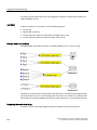
User manual
● WinCC flexible Micro
– describes the engineering basics based on the WinCC flexible Micro engineering
system (ES)
● WinCC flexible Compact/ Standard/ Advanced
– describes the engineering basics based on the WinCC flexible Compact,
WinCC flexible Standard and WinCC flexible Advanced engineering systems (ES)
● WinCC flexible Runtime:
– Describes how to commission and operate your Runtime project on a PC.
WinCC flexible 2007 Compact / Standard / Advanced
User's Manual, 07/2007, 6AV6691-1AB01-2AB0
3
Preface
● WinCC flexible Migration:
– Describes how to convert an existing ProTool project to WinCC flexible.
– Describes how to convert an existing WinCC project to WinCC flexible.
– Describes how to migrate ProTool projects with an HMI migration from OP3 to OP 73
or OP 73 micro.
– Describes how to migrate ProTool projects with an HMI migration from OP7 to OP 77B
or OP 77A.
– Describes how to migrate ProTool projects with an HMI migration from OP 17 to
OP 177B.
– describes how to migrate ProTool projects with HMI migration from RMOS graphic
devices to Windows CE devices.
● Communication:
– Communication Part 1 describes the connection of the HMI device to SIMATIC PLCs.
– Communication Part 2 describes the connection of the HMI device to third-party PLCs.
Operating Instructions
● Operating instructions for SIMATIC HMI devices:
– OP 73, OP 77A, OP 77B
– TP 170micro, TP 170A, TP 170B, OP 170B
– OP 73micro, TP 177micro
– TP 177A, TP 177B, OP 177B
– TP 270, OP 270
– TP 277, OP 277
– MP 270B
– MP 370
– MP 377
● Operating instructions for mobile SIMATIC HMI devices:
– Mobile Panel 170
– Mobile Panel 277
– Mobile Panel 277F IWLAN
– Mobile Panel 277 IWLAN
● Operating instructions (compact) for SIMATIC HMI devices:
– OP 77B
– Mobile Panel 170
4
WinCC flexible 2007 Compact / Standard / Advanced
User's Manual, 07/2007, 6AV6691-1AB01-2AB0
Preface
Getting Started
● WinCC flexible for first time users:
– Based on a sample project, this is a step-by-step introduction to the basics of
configuring screens, alarms, and recipes, and screen navigation.
● WinCC flexible for advanced users:
– Based on a sample project, this is a step-by-step introduction to the basics of
configuring logs, project reports, scripts, user management, and multilingual projects,
and integration into STEP 7.
● WinCC flexible options:
– Based on a sample project, this is a step-by-step introduction to the basics of
configuring the WinCC flexible Audit, Sm@rtServices, Sm@rtAccess and OPC Server
options.
Online availability
The following links provide direct access to technical documentation on SIMATIC products
and systems in English, German, French, Italian, and Spanish.
● SIMATIC Guide Technische Dokumentation in Deutsch:
"http://www.ad.siemens.de/simatic/portal/html_00/techdoku.htm"
● SIMATIC Guide for Technical Documentation in English:
"http://www.ad.siemens.de/simatic/portal/html_76/techdoku.htm"
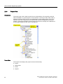
This Manual
Structure of this manual:
● Introduction to WinCC flexible – Chapter 1
● Working with WinCC flexible – Chapters 2 -17
● Transferring a project to an HMI device – Chapter 18
● Integration of WinCC flexible in STEP 7 – Chapter 19
● Appendix – Chapter 20
Conventions
A distinction is made in the naming conventions for the configuration and runtime software:
● "WinCC flexible 2007" refers to the configuration software.
● "Runtime" designates the runtime software running on the HMI devices.
● "WinCC flexible Runtime" designates the visualization product for use on standard PCs or
panel PCs.
The term "WinCC flexible" is used in the general context. A version name such as
"WinCC flexible 2007" is used whenever it is necessary to distinguish it from other versions.
WinCC flexible 2007 Compact / Standard / Advanced
User's Manual, 07/2007, 6AV6691-1AB01-2AB0
5
Preface
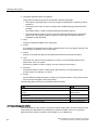
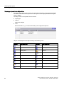
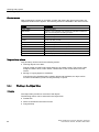
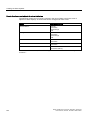
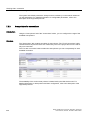
The following formatting is used to facilitate reading of the manual:
Notation
Scope
"Add screen"
•
•
•
Terminology that occurs in the user interface, e.g., dialog
names, tabs, buttons, menu commands.
Inputs required, e.g., limit values, tag values
Path information
"File > Edit"
Operational sequences, e.g., menu commands/shortcut menu
commands.
<F1>, <Alt>+<P>
Keyboard inputs
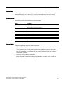
Please pay particular attention to such notices:
Note
Notes containing important information about the product and its use or a specific section of
the documentation to which you should pay particular attention.
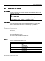
Trademarks
HMI®
SIMATIC®
SIMATIC HMI®
SIMATIC ProTool®
SIMATIC WinCC®
SIMATIC WinCC flexible®
Third parties using for their own purposes any other names in this documentation which refer
to trademarks might infringe upon the rights of the trademark owners.
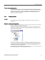
Additional support
Representatives and offices
If you have questions concerning the use of the described product which are not answered in
this manual, please contact the Siemens representative in your area.
Find your contact partner at:
"http://www.siemens.com/automation/partner"
A guide to the technical documentation for the various SIMATIC products and systems is
available at:
"http://www.siemens.com/simatic-tech-doku-portal"
The online catalog and the online ordering system is available at:
"http://mall.automation.siemens.com"
6
WinCC flexible 2007 Compact / Standard / Advanced
User's Manual, 07/2007, 6AV6691-1AB01-2AB0
Preface
Training center
To familiarize you with automation systems, we offer a variety of courses. Please contact
your regional training center or the central training center in D-90327 Nuremberg, Germany.
Phone: +49 (911) 895-3200
Internet: "http://www.sitrain.com"
Technical support
You can reach the technical support for all A&D products
via the support request form on the web:
"http://www.siemens.com/automation/support-request"
Phone: + 49 180 5050 222
Fax: + 49 180 5050 223
Additional information about our technical support is available in the Internet at:
"http://www.siemens.com/automation/service"
Service & support on the Internet
In addition to our documentation, we offer our complete knowledge base on the Internet at.
"http://www.siemens.com/automation/service&support"
There you will find:
● The newsletter which provides the latest information on your products.
● Relevant documentation for your application, which you can access via the search
function in our service & support database.
● A forum where users and experts from all over ther world exchange ideas.
● You local Automation & Drives representative.
● Information about on-site service, repairs, spare parts. Much more can be found on our
"Services" pages.
WinCC flexible 2007 Compact / Standard / Advanced
User's Manual, 07/2007, 6AV6691-1AB01-2AB0
7
Preface
8
WinCC flexible 2007 Compact / Standard / Advanced
User's Manual, 07/2007, 6AV6691-1AB01-2AB0
Table of contents
Preface ...................................................................................................................................................... 3
1
2
Introduction to WinCC flexible.................................................................................................................. 19
1.1
Introduction to SIMATIC HMI .......................................................................................................19
1.2
1.2.1
1.2.2
1.2.3
1.2.4
1.2.5
1.2.5.1
1.2.5.2
WinCC flexible system overview..................................................................................................20
Components of WinCC flexible ....................................................................................................20
WinCC flexible Engineering System ............................................................................................21
WinCC flexible Runtime ...............................................................................................................23
Available options..........................................................................................................................23
Licensing ......................................................................................................................................25
Licenses and License Key ...........................................................................................................25
WinCC flexible without licensing ..................................................................................................26
1.3
1.3.1
1.3.2
1.3.3
1.3.4
Automation concepts ...................................................................................................................27
Automation concepts with WinCC flexible ...................................................................................27
Remote access to HMI devices ...................................................................................................30
Automatic alarm dispatch.............................................................................................................31
Distributed HMI ............................................................................................................................32
1.4
1.4.1
1.4.2
1.4.3
1.4.4
1.4.5
1.4.5.1
1.4.5.2
1.4.5.3
1.4.6
Configuration concepts ................................................................................................................33
Configuration Support ..................................................................................................................33
Scalable Configuration Tools .......................................................................................................34
PLC-independent configuration ...................................................................................................35
Use...............................................................................................................................................35
Intelligent tools .............................................................................................................................36
Bulk data processing....................................................................................................................36
Configuring movement paths .......................................................................................................37
Graphic Configuration of the Screen Navigation .........................................................................38
Totally Integrated Automation ......................................................................................................39
WinCC flexible Engineering System ........................................................................................................ 41
2.1
Basic Principles on the Programming Interface...........................................................................41
2.2
2.2.1
2.2.2
2.2.3
2.2.4
2.2.5
2.2.6
2.2.7
2.2.8
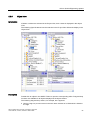
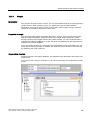
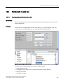
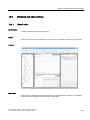
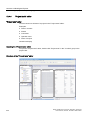
WinCC flexible user interface.......................................................................................................42
WinCC flexible User Interface Elements......................................................................................42
Menus and Toolbars ....................................................................................................................44
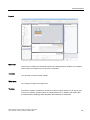
Work area.....................................................................................................................................45
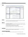
Project View .................................................................................................................................46
Property view ...............................................................................................................................47
Library ..........................................................................................................................................48
Output View..................................................................................................................................50
Object view...................................................................................................................................51
2.3
Placing editor-specific operating elements ..................................................................................52
2.4
Working with windows and toolbars.............................................................................................53
2.5
Working with the Mouse...............................................................................................................56
2.6
Keyboard control..........................................................................................................................58
WinCC flexible 2007 Compact / Standard / Advanced
User's Manual, 07/2007, 6AV6691-1AB01-2AB0
9
Table of contents
3
10
2.7
2.7.1
2.7.2
2.7.3
2.7.4
2.7.5
2.7.6
2.7.7
2.7.8
2.7.9
2.7.10
2.7.11
2.7.12
2.7.13
Working with WinCC flexible ....................................................................................................... 59
Working with WinCC flexible ....................................................................................................... 59
Working with projects .................................................................................................................. 59
Editing Multiple Projects with WinCC flexible.............................................................................. 60
Functional scope of a project ...................................................................................................... 60
Editor Properties ......................................................................................................................... 61
Open Editor ................................................................................................................................. 63
Switching between editors .......................................................................................................... 64
Object List ................................................................................................................................... 66
Function List................................................................................................................................ 67
Text List....................................................................................................................................... 69
Graphic list .................................................................................................................................. 73
Displaying Help ........................................................................................................................... 77
Customized setup of WinCC flexible........................................................................................... 78
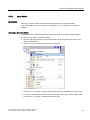
2.8
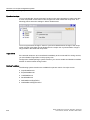
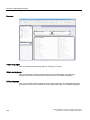
WinCC flexible Start Center ........................................................................................................ 79
Working with projects............................................................................................................................... 81
3.1
3.1.1
3.1.2
Basis for working with projects.................................................................................................... 81
Working with projects .................................................................................................................. 81
Component parts of a project...................................................................................................... 82
3.2
3.2.1
3.2.2
3.2.3
3.2.4
3.2.5
Types of projects......................................................................................................................... 83
Types of projects......................................................................................................................... 83
HMI device dependency of projects............................................................................................ 84
Configuring a project for several HMI devices ............................................................................ 86
Creating a project for use on different operating units................................................................ 88
WinCC flexible integrated in SIMOTION and STEP7 ................................................................. 88
3.3
Multilingual configuration............................................................................................................. 90
3.4
3.4.1
3.4.2
3.4.3
3.4.4
3.4.5
Editing projects............................................................................................................................ 91
Editing projects............................................................................................................................ 91
Displaying projects ...................................................................................................................... 93
Working in the Project View ........................................................................................................ 95
Working in the Object View ......................................................................................................... 96
Migrating existing projects........................................................................................................... 98
3.5
3.5.1
3.5.2
3.5.3
Converting projects ..................................................................................................................... 99
Projects of different WinCC flexible versions .............................................................................. 99
Differences between projects of different WinCC flexible versions .......................................... 100
Differentiation of HMI-device versions ...................................................................................... 102
3.6
3.6.1
3.6.2
3.6.3
3.6.4
3.6.5
3.6.6
Reusing project data ................................................................................................................. 103
Copying mechanisms................................................................................................................ 103
Flat copy.................................................................................................................................... 103
Copy .......................................................................................................................................... 105
Replace ..................................................................................................................................... 106
Using libraries ........................................................................................................................... 108
Using faceplates........................................................................................................................ 108
3.7
Working with the cross-reference ............................................................................................. 109
3.8
Overview of rewire .................................................................................................................... 110
3.9
Internal project find and replace feature ................................................................................... 110
3.10
Basic principles on documentation in WinCC flexible............................................................... 111
3.11
Consistency check during generation ....................................................................................... 111
WinCC flexible 2007 Compact / Standard / Advanced
User's Manual, 07/2007, 6AV6691-1AB01-2AB0
Table of contents
4
5
3.12
Debugging projects ....................................................................................................................112
3.13
3.13.1
3.13.2
Transferring projects ..................................................................................................................113
Basic Principles of the Transfer Operation ................................................................................113
Back transfer of projects ............................................................................................................114
Working with Tags ................................................................................................................................. 117
4.1
4.1.1
4.1.2
4.1.3
Basics.........................................................................................................................................117
Basics of tags.............................................................................................................................117
External tags ..............................................................................................................................118
Internal Tags ..............................................................................................................................119
4.2
4.2.1
4.2.2
Elements and basic settings ......................................................................................................120
Tag editor ...................................................................................................................................120
Basic Settings for Tags and Arrays ...........................................................................................121
4.3
4.3.1
4.3.2
4.3.3
4.3.4
4.3.5
4.3.6
4.3.7
4.3.8
4.3.9
Working with Tags .....................................................................................................................124
Properties of a Tag ....................................................................................................................124
Communication with the PLC using external tags .....................................................................125
Changing the tag configuration ..................................................................................................126
Tag limit values ..........................................................................................................................127
Start value of a tag.....................................................................................................................127
Updating the Tag Value in Runtime...........................................................................................128
Data logging ...............................................................................................................................129
Linear scaling a tag....................................................................................................................130
Indirect addressing of tags.........................................................................................................131
4.4
Array basics ...............................................................................................................................132
4.5
Examples of arrays ....................................................................................................................134
4.6
Cycle basics ...............................................................................................................................135
4.7
4.7.1
4.7.2
4.7.3
Working with structures..............................................................................................................136
Structure basics .........................................................................................................................136
Structures Editor ........................................................................................................................137
Managing structures ..................................................................................................................139
4.8
4.8.1
4.8.2
4.8.3
4.8.4
Importing Tags ...........................................................................................................................141
Importing Tags in WinCC flexible...............................................................................................141
Settings for the Tag Import ........................................................................................................141
Format of the Connection Data for the Import ...........................................................................143
Format of the Tag Data for the Import .......................................................................................144
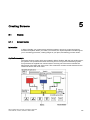
Creating Screens ................................................................................................................................... 147
5.1
5.1.1
5.1.2
5.1.3
5.1.4
Basics.........................................................................................................................................147
Screen Basics ............................................................................................................................147
HMI-based dependency of screens ...........................................................................................149
"Screens" Editor .........................................................................................................................150
Procedures.................................................................................................................................152
5.2
5.2.1
5.2.2
5.2.3
Configuring the navigation system.............................................................................................153
Navigating options .....................................................................................................................153
Graphic programming of the screen navigation system ............................................................153
Using the navigation control.......................................................................................................155
5.3
5.3.1
5.3.2
5.3.3
Working with objects ..................................................................................................................156
Overview of Objects...................................................................................................................156
Editing options of objects ...........................................................................................................160
Repositioning and resizing multiple objects...............................................................................161
WinCC flexible 2007 Compact / Standard / Advanced
User's Manual, 07/2007, 6AV6691-1AB01-2AB0
11
Table of contents
6
7
5.3.4
5.3.5
5.3.6
External graphics ...................................................................................................................... 161
Object Groups ........................................................................................................................... 163
Defining group properties.......................................................................................................... 164
5.4
Options of assigning dynamic update functions ....................................................................... 165
5.5
Working with function keys........................................................................................................ 166
5.6
The Advantage of Layers .......................................................................................................... 168
5.7
Object libraries .......................................................................................................................... 169
5.8
5.8.1
5.8.2
Working with faceplates ............................................................................................................ 171
Faceplate basics ....................................................................................................................... 171
Dynamic control options............................................................................................................ 173
Creating an Alarm System ..................................................................................................................... 175
6.1
6.1.1
6.1.2
6.1.2.1
6.1.2.2
6.1.2.3
6.1.3
6.1.4
6.1.4.1
6.1.4.2
6.1.4.3
6.1.4.4
Basics........................................................................................................................................ 175
Visualization of process and system alarms ............................................................................. 175
User-defined alarms.................................................................................................................. 175
Available Alarm Procedures...................................................................................................... 175
Acknowledging Alarms.............................................................................................................. 176
Alarm classes............................................................................................................................ 177
System alarms .......................................................................................................................... 178
Displaying Alarms ..................................................................................................................... 179
Displaying Alarms on the HMI Device....................................................................................... 179
Filtering the display of alarms ................................................................................................... 179
Logging and reporting alarms ................................................................................................... 180
System Functions for Alarm Editing.......................................................................................... 181
6.2
6.2.1
6.2.2
6.2.2.1
6.2.2.2
6.2.2.3
6.2.2.4
6.2.2.5
6.2.2.6
6.2.2.7
Elements and basic settings ..................................................................................................... 183
Alarm Components and Properties........................................................................................... 183
Editors for Configuring Alarms .................................................................................................. 184
Basic Principles of Editors......................................................................................................... 184
"Discrete alarms" editor............................................................................................................. 186
"Analog alarms" editor............................................................................................................... 187
"System alarms" editor.............................................................................................................. 188
"Alarm classes" editor ............................................................................................................... 189
"Alarm groups" editor ................................................................................................................ 190
Basic Settings for the Alarm System......................................................................................... 191
6.3
6.3.1
6.3.2
Working with alarms.................................................................................................................. 192
Reporting alarms....................................................................................................................... 192
Integrating alarms with the alarm numbering procedure .......................................................... 192
6.4
6.4.1
6.4.2
6.4.3
6.4.4
6.4.5
6.4.6
6.4.7
6.4.8
Alarm logging ............................................................................................................................ 195
Basic principles of alarm logging .............................................................................................. 195
Alarm logging ............................................................................................................................ 196
"Alarm logs" editor..................................................................................................................... 196
Basic settings for alarm logs ..................................................................................................... 197
Alarm logging ............................................................................................................................ 199
Displaying logged alarms on screens ....................................................................................... 200
Structure of a *.csv file with alarms........................................................................................... 200
Accessing the ODBC log database directly .............................................................................. 202
Working with a connection ..................................................................................................................... 203
7.1
7.1.1
7.1.2
12
Basics........................................................................................................................................ 203
Communication basics .............................................................................................................. 203
Principles of communication ..................................................................................................... 203
WinCC flexible 2007 Compact / Standard / Advanced
User's Manual, 07/2007, 6AV6691-1AB01-2AB0
Table of contents
8
9
7.2
7.2.1
7.2.2
7.2.3
Elements and basic settings ......................................................................................................206
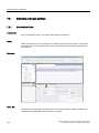
Connections Editor.....................................................................................................................206
Parameters for connections .......................................................................................................207
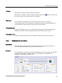
Area pointers for connections ....................................................................................................208
7.3
Connections and Protocols ........................................................................................................209
7.4
Ethernet connection ...................................................................................................................211
7.5
SNMP and MIB on HMIs............................................................................................................212
Structure of a recipe management system ............................................................................................ 213
8.1
8.1.1
8.1.2
8.1.3
8.1.4
8.1.5
8.1.6
8.1.7
8.1.8
Basics.........................................................................................................................................213
Basic principles of recipes .........................................................................................................213
Example for using recipes..........................................................................................................214
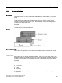
Structure of recipes....................................................................................................................215
Display of recipes.......................................................................................................................216
Transfer of recipe data records..................................................................................................217
Configuration of recipes .............................................................................................................220
Special features of the OP 77A and TP 177A ...........................................................................222
Synchronization of recipe data records with the PLC ................................................................223
8.2
8.2.1
8.2.2
8.2.3
8.2.4
Elements and basic settings ......................................................................................................225
"Recipes" editor..........................................................................................................................225
Recipe elements ........................................................................................................................226
Recipe data records...................................................................................................................228
Recipe settings...........................................................................................................................229
8.3
8.3.1
8.3.2
8.3.3
8.3.4
8.3.5
8.3.6
8.3.7
8.3.8
Viewing and editing recipes in Runtime.....................................................................................231
Recipe screen and recipe view ..................................................................................................231
Recipe view................................................................................................................................231
Configuration options for the recipe view...................................................................................233
Behavior of the recipe view in Runtime .....................................................................................236
Recipe screen ............................................................................................................................237
Operator input of the recipe view ...............................................................................................239
Operator input of the simple recipe view ...................................................................................241
Reactions to modifications of the recipe structure .....................................................................244
8.4
8.4.1
8.4.2
8.4.3
Scenarios ...................................................................................................................................245
Scenario: Entering recipe data records in Runtime ...................................................................245
Scenario: Manual production sequence ....................................................................................246
Scenario: Automatic production sequence ................................................................................247
Logging and displaying tags .................................................................................................................. 249
9.1
9.1.1
9.1.2
9.1.3
Basics.........................................................................................................................................249
Basic principles for data logging ................................................................................................249
Data logging in WinCC flexible ..................................................................................................249
Trends ........................................................................................................................................251
9.2
9.2.1
9.2.2
Elements and basic settings ......................................................................................................253
"Data Logs" editor ......................................................................................................................253
Basic settings for data logs ........................................................................................................254
9.3
Logging tab values.....................................................................................................................256
9.4
9.4.1
9.4.2
9.4.3
Outputting logged data...............................................................................................................258
Outputting tag values in screens................................................................................................258
The structure of a *.csv file with tag values ...............................................................................258
Accessing the ODBC log database directly ...............................................................................259
WinCC flexible 2007 Compact / Standard / Advanced
User's Manual, 07/2007, 6AV6691-1AB01-2AB0
13
Table of contents
10
11
12
14
Working with reports .............................................................................................................................. 261
10.1
Principles on the report system................................................................................................. 261
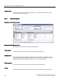
10.2
Structure of reports ................................................................................................................... 262
10.3
10.3.1
10.3.2
Elements and basic settings ..................................................................................................... 264
Editor "reports" .......................................................................................................................... 264
Using the toolbox view .............................................................................................................. 265
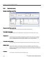
10.4
10.4.1
10.4.2
10.4.3
10.4.4
Working with reports ................................................................................................................. 266
Creating a report ....................................................................................................................... 266
Adapting the report properties .................................................................................................. 267
Objects for report creation......................................................................................................... 269
Use of report objects ................................................................................................................. 270
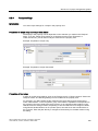
10.5
10.5.1
10.5.2
Reporting alarms....................................................................................................................... 271
Reporting alarms....................................................................................................................... 271
Process output parameters for an alarm protocol..................................................................... 271
10.6
10.6.1
10.6.2
Reporting recipes ...................................................................................................................... 274
Reporting recipes ...................................................................................................................... 274
Editing output parameters for a recipe report ........................................................................... 275
10.7
Outputting a report .................................................................................................................... 278
User administration................................................................................................................................ 279
11.1
Field of application of the user administration........................................................................... 279
11.2
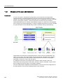
Structure of the user administration .......................................................................................... 280
11.3
11.3.1
11.3.2
11.3.3
11.3.4
11.3.5
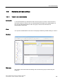
Elements and basic settings ..................................................................................................... 281
"Users" user administration....................................................................................................... 281
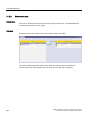
"Groups" user administration .................................................................................................... 283
Users work area ........................................................................................................................ 284
User groups work area.............................................................................................................. 285
Runtime security settings .......................................................................................................... 286
11.4
11.4.1
11.4.2
11.4.3
11.4.4
Working with the user administration ........................................................................................ 289
Central user administration using SIMATIC Logon................................................................... 289
Users in Runtime....................................................................................................................... 290
User view .................................................................................................................................. 291
Access security ......................................................................................................................... 293
System functions and runtime scripting ................................................................................................. 295
12.1
12.1.1
12.1.2
12.1.3
12.1.4
12.1.5
Basics........................................................................................................................................ 295
System functions and runtime scripting .................................................................................... 295
System functions....................................................................................................................... 297
Use of system functions ............................................................................................................ 298
Scripts ....................................................................................................................................... 299
Use of scripts ............................................................................................................................ 300
12.2
12.2.1
12.2.2
Working with function lists......................................................................................................... 301
Basic principles of the functions list .......................................................................................... 301
Properties of a function list........................................................................................................ 302
12.3
12.3.1
12.3.2
12.3.3
Elements and basic settings ..................................................................................................... 303
"Script" editor ............................................................................................................................ 303
Properties of the "Script" editor ................................................................................................. 304
Basic settings ............................................................................................................................ 308
12.4
Creating scripts ......................................................................................................................... 310
WinCC flexible 2007 Compact / Standard / Advanced
User's Manual, 07/2007, 6AV6691-1AB01-2AB0
Table of contents
13
14
12.4.1
12.4.2
12.4.3
12.4.4
12.4.5
Access to tags............................................................................................................................310
Call up of scripts and system functions in the scripts ................................................................311
Access to objects .......................................................................................................................312
Synchronization of tags and objects ..........................................................................................313
Store script .................................................................................................................................313
12.5
12.5.1
12.5.2
Debugging..................................................................................................................................314
Debugging Scripts......................................................................................................................314
Integrating the debugger............................................................................................................314
12.6
12.6.1
12.6.2
12.6.3
12.6.4
12.6.5
Runtime behavior of functions in runtime ..................................................................................320
Completion of the function list in runtime...................................................................................320
Processing of scripts in runtime .................................................................................................320
Delivery and return of values .....................................................................................................321
Changing of object properties in runtime with VBS ...................................................................322
HMI device dependent system functions in the script................................................................322
Structure of Multilingual Projects ........................................................................................................... 323
13.1
Working with multiple languages ...............................................................................................323
13.2
WinCC flexible terminology........................................................................................................324
13.3
13.3.1
13.3.2
13.3.3
Language Settings .....................................................................................................................326
Language settings in the operating system ...............................................................................326
Operating system settings for Asian languages ........................................................................327
"Project Languages" editor ........................................................................................................327
13.4
13.4.1
13.4.2
13.4.3
13.4.4
13.4.5
Creating a project in multiple languages....................................................................................329
Creating a project in multiple languages....................................................................................329
Specific features of Asian and Eastern languages in the engineering system..........................330
Translating project texts in the editor.........................................................................................331
"Project texts" editor...................................................................................................................332
Exchanging texts with translators ..............................................................................................333
13.5
13.5.1
13.5.2
13.5.3
Working with dictionaries ...........................................................................................................335
Working with dictionaries ...........................................................................................................335
"System dictionary" editor ..........................................................................................................336
"User dictionary" editor ..............................................................................................................337
13.6
13.6.1
13.6.2
Use of language-dependent graphics........................................................................................338
Use of language-dependent graphics........................................................................................338
"Graphics" editor ........................................................................................................................338
13.7
13.7.1
13.7.2
13.7.3
Languages in Runtime ...............................................................................................................340
Languages in Runtime ...............................................................................................................340
Configuring language switching .................................................................................................340
Specific features of Asian and Eastern languages in Runtime..................................................341
Project documentation ........................................................................................................................... 343
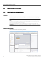
14.1
14.1.1
14.1.2
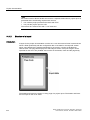
Basics.........................................................................................................................................343
Project documentation ...............................................................................................................343
Structure of a layout...................................................................................................................344
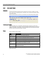
14.2
14.2.1
14.2.2
Using layouts..............................................................................................................................346
Using layouts..............................................................................................................................346
Editing a layout for the project documentation...........................................................................347
14.3
14.3.1
14.3.2
Creating a project report ............................................................................................................349
Selecting the data for a project report........................................................................................349
Outputting of data of selected objects .......................................................................................349
WinCC flexible 2007 Compact / Standard / Advanced
User's Manual, 07/2007, 6AV6691-1AB01-2AB0
15
Table of contents
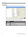
14.3.3
15
16
17
18
19
Mobile Wireless ..................................................................................................................................... 351
15.1
15.1.1
15.1.2
Basic principles ......................................................................................................................... 351
Field of application for the Mobile Panel Wireless .................................................................... 351
How the Mobile Panel Wireless works...................................................................................... 352
15.2
15.2.1
15.2.2
15.2.3
15.2.4
Elements and basic settings ..................................................................................................... 356
Zones ........................................................................................................................................ 356
Zones working area................................................................................................................... 357
Effective ranges ........................................................................................................................ 358
Effective ranges working area................................................................................................... 359
15.3
Working with effective ranges ................................................................................................... 361
Planning jobs ......................................................................................................................................... 363
16.1
Field of application of the scheduler ......................................................................................... 363
16.2
Working with jobs and events ................................................................................................... 364
16.3
16.3.1
16.3.2
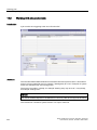
Elements ................................................................................................................................... 366
"Scheduler" editor ..................................................................................................................... 366
Work area of the "Scheduler" editor.......................................................................................... 367
Managing project versions ..................................................................................................................... 369
17.1
Applications for project versioning ............................................................................................ 369
17.2
Basics of version management................................................................................................. 370
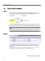
17.3
Trunk ......................................................................................................................................... 371
17.4
Branch ....................................................................................................................................... 372
17.5
17.5.1
17.5.2
17.5.3
17.5.4
Elements ................................................................................................................................... 374
"Project versions" editor ............................................................................................................ 374
Change log operator controls.................................................................................................... 375
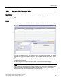
Version Management Work Area.............................................................................................. 376
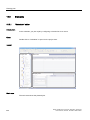
Property view ............................................................................................................................ 377
17.6
17.6.1
Working with project versions ................................................................................................... 378
Comparing versions .................................................................................................................. 378
Logging changes ................................................................................................................................... 379
18.1
Applications for the change log................................................................................................. 379
18.2
Change log of a project ............................................................................................................. 380
18.3
Change log of a project session................................................................................................ 381
18.4
Change log of a project under version management................................................................ 383
18.5
18.5.1
18.5.2
18.5.3
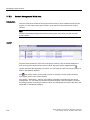
Elements ................................................................................................................................... 384
"Change log" editor ................................................................................................................... 384
Change log operator controls.................................................................................................... 385
Change log work area ............................................................................................................... 386
Transfer ................................................................................................................................................. 387
19.1
19.1.1
19.1.2
19.1.3
19.1.4
16
Selecting Objects for the Project Documentation ..................................................................... 350
Basics........................................................................................................................................ 387
Basic Principles of the Transfer Operation ............................................................................... 387
Transfer settings ....................................................................................................................... 388
Transfer via USB....................................................................................................................... 391
Back transfer of projects ........................................................................................................... 392
WinCC flexible 2007 Compact / Standard / Advanced
User's Manual, 07/2007, 6AV6691-1AB01-2AB0
Table of contents
19.2
19.2.1
19.2.2
19.2.3
19.2.4
19.2.5
20
21
Managing Files on the HMI Device ............................................................................................394
ProSave .....................................................................................................................................394
Backup of HMI data ...................................................................................................................394
Updating the operating system ..................................................................................................396
Transferring authorizations ........................................................................................................397
Installation of options .................................................................................................................398
Integration of WinCC flexible in STEP 7 ................................................................................................ 399
20.1
20.1.1
20.1.2
20.1.3
20.1.4
20.1.5
20.1.6
20.1.7
20.1.8
20.1.8.1
20.1.8.2
20.1.8.3
20.1.9
Basic Principles..........................................................................................................................399
Restrictions for integrated projects ............................................................................................399
Converting integrated projects ...................................................................................................399
Basic principles of integration in STEP 7...................................................................................400
Working with the SIMATIC Manager .........................................................................................402
Working with HW Config ............................................................................................................402
Configuring connections ............................................................................................................403
Working with objects ..................................................................................................................404
Converting an integrated project................................................................................................406
Conversion of integrated WinCC flexible projects in STEP 7 ....................................................406
Converting an integrated project to the current WinCC flexible version ....................................408
Converting an integrated project to an earlier WinCC flexible version ......................................409
Integrating WinCC flexible in a PC Station ................................................................................410
20.2
20.2.1
20.2.2
Configuring communication settings..........................................................................................412
Configuring communication settings via routing ........................................................................412
Project transfer via S7 routing....................................................................................................414
20.3
20.3.1
20.3.2
Tag configuration .......................................................................................................................418
Configuring tags with the Tag editor ..........................................................................................418
Connecting a tag via the application point .................................................................................420
20.4
20.4.1
Configuring alarms.....................................................................................................................421
Integrating alarms with the alarm numbering procedure ...........................................................421
Appendix................................................................................................................................................ 423
21.1
Open Source Software...............................................................................................................423
21.2
21.2.1
21.2.1.1
21.2.1.2
21.2.1.3
21.2.1.4
21.2.1.5
21.2.1.6
21.2.1.7
21.2.2
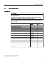
21.2.2.1
Performance features ................................................................................................................424
General Technical Data .............................................................................................................424
Released operating systems......................................................................................................424
Released databases ..................................................................................................................424
Further software versions supported .........................................................................................425
Recommended printers..............................................................................................................425
Legal characters ........................................................................................................................425
Memory requirement of recipes .................................................................................................425
Memory space requirements for recipes of special devices......................................................427
System limits ..............................................................................................................................428
System limits ..............................................................................................................................428
Index...................................................................................................................................................... 441
WinCC flexible 2007 Compact / Standard / Advanced
User's Manual, 07/2007, 6AV6691-1AB01-2AB0
17
Table of contents
18
WinCC flexible 2007 Compact / Standard / Advanced
User's Manual, 07/2007, 6AV6691-1AB01-2AB0
Introduction to WinCC flexible
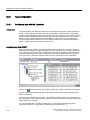
1.1
1
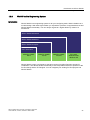
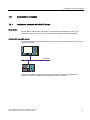
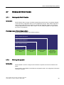
Introduction to SIMATIC HMI
Introduction
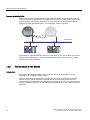
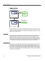
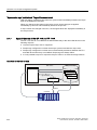
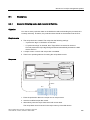
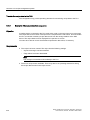
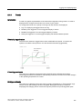
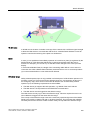
Maximum transparency is essential for the operator who works in an environment where
processes are becoming more complex, and requirements for machine and plant
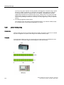
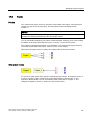
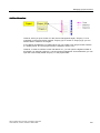
functionality are increasing. The Human Machine Interface (HMI) provides this transparency.
The HMI system represents the interface between man (operator) and process
(machine/plant). The PLC is the actual unit which controls the process. Hence, there is an
interface between the operator and WinCC flexible (at the HMI device) and an interface
between WinCC flexible and the PLC. An HMI system assumes the following tasks:
● Process visualization
The process is visualized on the HMI device. The screen on the HMI device is
dynamically updated. This is based on process transitions.
● Operator control of the process
The operator can control the process by means of the GUI. For example, the operator
can preset reference values for the controls or start a motor.
● Displaying alarms
Critical process states automatically trigger an alarm, for example, when the setpoint
value is exceeded.
● Archiving process values and alarms
The HMI system can log alarms and process values. This feature allows you to log
process sequences and to retrieve previous production data.
● Process values and alarms logging
The HMI system can output alarms and process value reports. This allows you to print
out production data at the end of a shift, for example.
● Process and machine parameter management
The HMI system can store the parameters of processes and machines in recipes. For
example, you can download these parameters in one pass from the HMI device to the
PLC to change over the product version for production.
WinCC flexible 2007 Compact / Standard / Advanced
User's Manual, 07/2007, 6AV6691-1AB01-2AB0
19
Introduction to WinCC flexible
1.2 WinCC flexible system overview
SIMATIC HMI
SIMATIC HMI offers a totally integrated, single-source system for manifold operator control
and monitoring tasks. With SIMATIC HMI, you always master the process and always keep
your machinery and units running.
Examples of simple SIMATIC HMI systems are small touch panels for use at machine level.
SIMATIC HMI systems used for controlling and monitoring production plants represent the
upper end of the performance spectrum. These include high-performance client/server
systems.
Integration of SIMATIC WinCC flexible
WinCC flexible is the HMI software for future-proof machine-oriented automation concepts
with comfortable and highly efficient engineering. WinCC flexible combines the following
benefits:
● Straightforward handling
● Transparency
● Flexibility
1.2
WinCC flexible system overview
1.2.1
Components of WinCC flexible
WinCC flexible Engineering System
The WinCC flexible Engineering System is the software for handling all your essential
configuring tasks. The WinCC flexible edition determines which HMI devices in the
SIMATIC HMI spectrum can be configured.
WinCC flexible Runtime
WinCC flexible Runtime is your software for process visualization. You execute the project in
process mode in Runtime.
WinCC flexible options
The WinCC flexible options allow you to expand the standard functionality of WinCC flexible.
A separate license is needed for each option.
20
WinCC flexible 2007 Compact / Standard / Advanced
User's Manual, 07/2007, 6AV6691-1AB01-2AB0
Introduction to WinCC flexible
1.2 WinCC flexible system overview
1.2.2
WinCC flexible Engineering System
Introduction
WinCC flexible is an engineering system for all your configuring tasks. WinCC flexible has a
modular design. With each higher edition you expand the spectrum of supported devices and
WinCC flexible functionality. You can always migrate to a higher edition by means of a
PowerPack.
:LQ&&IOH[LEOH$GYDQFHG
:LQ&&IOH[LEOH6WDQGDUG
:LQ&&IOH[LEOH&RPSDFW
:LQ&&IOH[LEOH0LFUR
6,0$7,&3$1(/
0LFUR
6,0$7,&3$1(/
6,0$7,&3$1(/
3&EDVHG
:LQGRZV
:LQGRZV;3
WinCC flexible covers a performance spectrum ranging from Micro Panels to simple PC
visualization. The WinCC flexible functionality is thus comparable with that of products of the
ProTool family and the TP Designer. You can integrate your existing ProTool projects into
WinCC flexible.
WinCC flexible 2007 Compact / Standard / Advanced
User's Manual, 07/2007, 6AV6691-1AB01-2AB0
21
Introduction to WinCC flexible
1.2 WinCC flexible system overview
Principle
The WinCC flexible workbench opens on the screen of your programming computer when
you create a new or open an existing project in WinCC flexible. The project structure is
visualized and the project managed in the "Project View".
3URMHFWYLHZ
:RUNDUHD
7RROZLQGRZ
3URSHUW\YLHZ
2EMHFWYLHZ
2XWSXWYLHZ
WinCC flexible provides a special editor for each configuring task. For example, you
configure the GUI of an HMI device in the "Screens" editor. Or you can use the "Discrete
Alarms" editor to configure alarms.
All project configuration data related to a project is stored in the project database.
Migration to another WinCC flexible edition
Your current WinCC flexible edition determines which HMI devices you can configure. To
configure an HMI device which is not supported in your current WinCC flexible edition, you
can migrate to another WinCC flexible edition. All existing functions remain available.
As of the WinCC flexible Compact edition, you can use the PowerPack to upgrade the
WinCC flexible edition.
WinCC flexible Asia editions
Only the "Advanced" and "Standard" editions are available for the WinCC flexible ASIA
version.
22
WinCC flexible 2007 Compact / Standard / Advanced
User's Manual, 07/2007, 6AV6691-1AB01-2AB0
Introduction to WinCC flexible
1.2 WinCC flexible system overview
1.2.3
WinCC flexible Runtime
Principle
In runtime, the operator can control and monitor the process. This involves in particular the
following tasks:
● Communication with the automation systems.
● On-screen visualization of images
● Operating the process, for example, by setting setpoint values or opening and closing
valves.
● Archiving of current runtime data, e.g. process values and alarm events.
Performance spectrum of WinCC flexible Runtime
WinCC flexible Runtime supports a certain number of process variables (Powertags) which
is determined by your license:
● WinCC flexible Runtime 128: Supports 128 process variables
● WinCC flexible Runtime 512: Supports 512 process variables
● WinCC flexible Runtime 2048: Supports 2048 process variables
You can increase the number of process variables with a PowerPack.
1.2.4
Available options
Introduction
Options are available for the following components:
● WinCC flexible Engineering System
● WinCC flexible Runtime on PC-based HMI devices
● Non-PC-based HMI devices
You can operate device-dependent runtime options on the HMI devices.
Each option requires a license.
WinCC flexible 2007 Compact / Standard / Advanced
User's Manual, 07/2007, 6AV6691-1AB01-2AB0
23
Introduction to WinCC flexible
1.2 WinCC flexible system overview
Options for WinCC flexible Engineering System
Options available for the WinCC flexible Engineering System:
SIMATIC
WinCC flexible options
Function
Availability
WinCC flexible
/ChangeControl
Version management and modification
tracking
WinCC flexible Compact/
Standard/ Advanced
Options for WinCC flexible Runtime
The options depend on the target system used. The following options are available for
WinCC flexible Runtime on PC-based HMI devices or for non-PC-based HMI devices:
SIMATIC
WinCC flexible RT
options
Function
Non-PC-based HMI
devices
SIMATIC panel
PCs
WinCC flexible
/Archives
Archiving functionality in runtime
From Panel 270
x
WinCC flexible
/Recipes
Recipe functionality in runtime
Device-dependent
available; no
licensing necessary.
x
WinCC flexible
/Sm@rtAccess
Remote control and remote
monitoring as well as
communication between different
SIMATIC HMI systems.
From Panel 270
x
WinCC flexible
/Sm@rtService
Remote maintenance and servicing From Panel 270
of machines/plants via the
Internet/Intranet.
x
WinCC flexible
/OPC-Server
Use of an HMI device as OPC
server
Multi panel
x
WinCC flexible
/ProAgent
Process diagnostics during runtime
From Panel 270
x
WinCC flexible /Audit
Reporting interactions according to
FDA
From Panel 270
x
Note
The mutual use of the options Sm@rtAccess and Sm@rtService with the option Audit is not
enabled.
24
WinCC flexible 2007 Compact / Standard / Advanced
User's Manual, 07/2007, 6AV6691-1AB01-2AB0
Introduction to WinCC flexible
1.2 WinCC flexible system overview
1.2.5
Licensing
1.2.5.1
Licenses and License Key
Principle
All WinCC flexible editions require a license. Certain WinCC flexible editions require a
license to be used without restriction.
● License
You receive your license on paper. The license entitles you to install and use your
purchased WinCC flexible edition on a computer. More information about rights of use is
available in the electronic catalog CA 01.
● License Key
The license key is delivered on a separate copy-protected USB stick. During setup you
are requested to insert the USB stick which contains the License Key.
The data carrier which contains the License Keys is named as storage location in all
other documents.
Licenses for the WinCC flexible Engineering System
Which licensing model is going to be used depends on the WinCC flexible edition. The
edition is activated by means of the purchased license, that is, the License Key you installed:
● WinCC flexible Micro: License agreement
● WinCC flexible Compact/Standard/Advanced :
– License agreement and License Key for WinCC flexible Compact on USB stick
– License agreement and License Key for WinCC flexible Standard on USB stick
– License agreement and License Key for WinCC flexible Advanced on USB stick
Licenses for WinCC flexible Runtime
WinCC flexible Runtime is licensed using the license agreement and the License Key.
WinCC flexible Runtime licenses support a different amount of variables:
● WinCC flexible Runtime 128: Supports 128 process variables
● WinCC flexible Runtime 512: Supports 512 process variables
● WinCC flexible Runtime 2048: Supports 2048 process variables
WinCC flexible 2007 Compact / Standard / Advanced
User's Manual, 07/2007, 6AV6691-1AB01-2AB0
25
Introduction to WinCC flexible
1.2 WinCC flexible system overview
Licenses for the options packages
You receive a license and a License Key on USB stick for each option. WinCC flexible
Engineering System already contains the functionality of the Runtime options package. You
do not need a license on your programming computer for configuring the functionality of a
runtime option.
1.2.5.2
WinCC flexible without licensing
Principle
Without a license, WinCC flexible runs in demo mode only and the software operability are
restricted. Alarms which need acknowledging appear regularly on the screen both in
WinCC flexible Engineering System and in WinCC flexible Runtime.
Requesting a new License Key
Contact customer support if the storage location of your License Key was damaged or lost.
The storage location of the License Key may be a floppy disk or USB stick.
26
WinCC flexible 2007 Compact / Standard / Advanced
User's Manual, 07/2007, 6AV6691-1AB01-2AB0
Introduction to WinCC flexible
1.3 Automation concepts
1.3
Automation concepts
1.3.1
Automation concepts with WinCC flexible
Introduction
WinCC flexible supports the configuration of many different automation concepts. The
following automation concepts can be implemented by default using WinCC flexible.
Control with one HMI device
An HMI device which is directly connected to the PLC via the process bus is referred to as a
single-user system.
352),%86
Single-user systems are generally used near production, but can also be deployed to
operate and monitor independent part processes or system sections.
WinCC flexible 2007 Compact / Standard / Advanced
User's Manual, 07/2007, 6AV6691-1AB01-2AB0
27
Introduction to WinCC flexible
1.3 Automation concepts
PLC with several HMI devices
Several HMI devices are connected to one or more PLCs via a process bus
(e.g. PROFIBUS or Ethernet).
352),%86
Such systems are deployed, for example, in a production line to operate the plant from
several points.
28
WinCC flexible 2007 Compact / Standard / Advanced
User's Manual, 07/2007, 6AV6691-1AB01-2AB0
Introduction to WinCC flexible
1.3 Automation concepts
HMI System with centralized functions
An HMI system is connected to a PC via Ethernet. The upstream PC assumes central
functions, e.g. recipe management. The necessary recipe data records are provided by the
subordinate HMI system.
WinCC flexible 2007 Compact / Standard / Advanced
User's Manual, 07/2007, 6AV6691-1AB01-2AB0
29
Introduction to WinCC flexible
1.3 Automation concepts
Support for Mobile Units
Mobile units are mainly implemented in large production plants, long production lines or in
conveyor technology, but can also be implemented in systems in which direct visual contact
with the process is necessary. The machines to be operated are equipped with several
interfaces to which the Mobile Panel 170, for example, can be connected.
352),%86
The operator or service technician can thus work directly on site. This enables an accurate
setting up and positioning, e.g. during the startup phase. In the case of servicing, mobile
units ensure shorter downtimes.
1.3.2
Remote access to HMI devices
Introduction
By using the Sm@rtService option, it is possible to connect to an HMI device from a
workstation via a network (Internet, LAN).
Example: A medium-sized production company has a service contract with an external
service company. When servicing is required, the service technician responsible can
remotely access the HMI device and display its user interface directly on his workstation. In
this way, updated projects can be transferred more quickly which, in turn, reduces machine
downtime.
30
WinCC flexible 2007 Compact / Standard / Advanced
User's Manual, 07/2007, 6AV6691-1AB01-2AB0
Introduction to WinCC flexible
1.3 Automation concepts
Application Possibilities
The option "Sm@rtService" is required for implementation.
/$17&3,3
352),%86
Remote access via a network can be used for the following applications:
● Remote operation and monitoring
An HMI device can be operated and running processes monitored from your own
workstation.
● Remote administration
A project can be transferred from a workstation to an HMI device. In this way, projects
can be updated from a central point.
● Remote diagnostics
Each Panel provides HTML pages for accessing the installed software, version or system
alarms using a Web browser.
1.3.3
Automatic alarm dispatch
Introduction
A machine which fails due to a fault costs money. An alarm that reaches the service
technician in a timely manner helps to minimize unplanned downtime.
Example: Contamination in a feed line reduces the flow of coolant. When the value drops
below the configured limit value, the HMI device displays a warning. The warning is also
dispatched as an e-mail to the service technician responsible.
WinCC flexible 2007 Compact / Standard / Advanced
User's Manual, 07/2007, 6AV6691-1AB01-2AB0
31
Introduction to WinCC flexible
1.3 Automation concepts
Principle
The "Sm@rtAccess" option is required for implementation. In order to send alarms as
e-mails, the HMI system must have access to an e-mail server.
The e-mail client sends the alarms via intranet or Internet. The automatic alarm dispatch
ensures that all the people involved (e.g. shift foreman and sales manager) are informed of
the status of the machine in good time.
1.3.4
Distributed HMI
Introduction
Distributed HMI enables the operation of a machine from several synchronized operating
stations. All the operating stations display the same process screen. The operating
authorization is transferred intelligently.
Principle
The "Sm@rtAccess" option is required for implementation.
Only one HMI device contains the configuration data and functions as the server. The server
can be controlled from the other operator devices. All the HMI devices display the same
screens.
32
WinCC flexible 2007 Compact / Standard / Advanced
User's Manual, 07/2007, 6AV6691-1AB01-2AB0
Introduction to WinCC flexible
1.4 Configuration concepts
1.4
Configuration concepts
1.4.1
Configuration Support
Introduction
WinCC flexible is used to configure user interfaces to operate and monitor machines and
plants. WinCC flexible provides support for the configuration tasks in the form of solutionoriented concepts. For example, this could concern the processing of bulk data, automatic
transfers or even the intelligent configuration of movement paths.
Engineering support
Efficient configuration saves time and costs. WinCC flexible supports the following for this:
● Target system dependent configuration
During configuration, only those functions supported by the selected target system are
displayed.
● Engineering independent of the PLC used
If you use a project for different or several target systems, you only switch over the HMI
device in the project. Functionalities of the selected HMI device which are not supported
are not displayed.
● Central modification of referenced objects
Modifications made at a central station are applied to the entire project.
● Use
The reuse of configuration objects simplifies configuration and reduces overall costs.
● Bulk data processing
Create an action, for example, with several tags having the same values or
chronologically ascending addresses.
● Graphic Configuration of the Screen Navigation
Create a screen hierarchy from the graphic overview of the configured screens. The
required objects for the screen navigation are generated automatically.
● Configuring movement paths
Configure the movement of objects clearly in the process screen.
● Totally Integrated Automation
Benefit from the smooth integration of WinCC flexible in the configuration user interface
of SIMATIC STEP 7 and SIMOTION SCOUT.
User customization of the programming user interface
The WinCC flexible Workbench can be user customized by moving or hiding windows and
toolbars.
WinCC flexible 2007 Compact / Standard / Advanced
User's Manual, 07/2007, 6AV6691-1AB01-2AB0
33
Introduction to WinCC flexible
1.4 Configuration concepts
1.4.2
Scalable Configuration Tools
Introduction
If WinCC flexible is used to edit projects for different HMI devices, the functional scope is
adapted to the HMI device during configuration. Different functionality is available according
to the HMI device.
Custom HMI Device Functions
Custom device functions ensure efficient configuration. You only need to configure those
functions which are supported by the specific HMI device.
The editors displayed in the Project View can be used, for example, to quickly detect which
functions are supported by the HMI device selected.
You can use a project for different target systems. If the target system is changed, only the
view of the project data is modified. When the target system changes, configured objects are
not deleted; they are only hidden if some features are not supported by the target system.
34
WinCC flexible 2007 Compact / Standard / Advanced
User's Manual, 07/2007, 6AV6691-1AB01-2AB0
Introduction to WinCC flexible
1.4 Configuration concepts
Customized setup of the configuration user interface
WinCC flexible allows you to customize the position and reaction of windows and toolbars.
This allows you to configure the work environment to meet your special requirements.
The configuration of the WinCC flexible workbench is linked to the user logged on in
Microsoft Windows. On saving the project, the positions and behavior of windows and
toolbars are automatically saved with it.
When opened again, the positions and behavior of windows and toolbars are identical to
when the project was last saved. When the working environment opens, it is identical to the
configuration when last closed. This is also the case when a project edited by a different
project planner is opened.
1.4.3
PLC-independent configuration
Introduction
WinCC flexible supports you in creating configurations independent on the destination
system.
Example: A machine has three operating stations. One HMI device with average
performance connected to one of these operating stations is sufficient.
Principle
The project need not be recreated for this HMI device. Simply switch the HMI device in the
project instead.
Functions not supported by the HMI device are hidden.
The different HMI devices should not differ too much in their resolution and functionality .
1.4.4
Use
Introduction
Reusing configuration objects facilitates configuration work. Centralized editing saves a
considerable portion of the configuration work when an object is changed.
Faceplates
Simple screen objects can be combined as faceplates to form complex objects. For each
faceplate, it is possible to define which properties of the screen objects can be changed. By
reusing a faceplate stored in the library, modifications can be executed throughout the entire
project from a central point.
WinCC flexible 2007 Compact / Standard / Advanced
User's Manual, 07/2007, 6AV6691-1AB01-2AB0
35
Introduction to WinCC flexible
1.4 Configuration concepts
Libraries
All configuration objects can be stored centrally in libraries. In addition, numerous
preconfigured screen objects are supplied which can be used to design process screens
appropriately.
Text Libraries
Text libraries can be used to store all configuration texts in several languages. If a project is
configured in several languages, the texts can be translated automatically.
1.4.5
Intelligent tools
1.4.5.1
Bulk data processing
Introduction
Bulk data management provides support in the simultaneous creation and editing of several
objects. Configuration is more efficient, saving time and costs.
Example: A part of the tag inventory is assumed from an old project but the inventory has the
wrong tag type. Using WinCC flexible, the tag type can be modified for all tags in one
working step.
Principle
The advantages of bulk data processing can be used when creating and editing specific
objects (e.g. tags).
● Automatic address assignment
If several tags, created with process linking, are stored successively in the controller
memory, the address area can be increased automatically for each tag.
● Multiple modification
Identical modifications for several tags can be executed in one step, e.g. changing the tag
type or the controller.
36
WinCC flexible 2007 Compact / Standard / Advanced
User's Manual, 07/2007, 6AV6691-1AB01-2AB0
Introduction to WinCC flexible
1.4 Configuration concepts
1.4.5.2
Configuring movement paths
Introduction
Process sequences involving object movement can be clearly displayed on the HMI device,
e.g. the transport of a product on a conveyor belt.
Movement paths simplify the configuration of movements of objects in the process screen.
The movement process is represented on the screen by a diagram.
Principle
The movement path for an object is defined in the process screen. The movement path is
composed of the starting point and finishing point. The movement path is assigned a tag.
The tag value defines the relative position of the object on the movement path in runtime.
WinCC flexible 2007 Compact / Standard / Advanced
User's Manual, 07/2007, 6AV6691-1AB01-2AB0
37
Introduction to WinCC flexible
1.4 Configuration concepts
1.4.5.3
Graphic Configuration of the Screen Navigation
Introduction
Screen navigation means configured hierarchy for process screens. Using the screen
navigation, a fixed navigation structure is defined for a project. Operators can use the
navigation control in runtime to navigate between the various screens of the structure.
Principle
Use the Screen Navigation editor to place screens in the required location in the screen
hierarchy using drag-and-drop. You can also create a direct link between screens that are
not integrated in the hierarchy. The navigation buttons can be pasted in the process screen.
The creation of a navigation structure offers the following advantages:
● Overview of the navigation structure throughout the entire project.
● Quick creation of direct links between process screens.
● Automatic creation of the basic screen navigation.
38
WinCC flexible 2007 Compact / Standard / Advanced
User's Manual, 07/2007, 6AV6691-1AB01-2AB0
Introduction to WinCC flexible
1.4 Configuration concepts
1.4.6
Totally Integrated Automation
Introduction
A full automation solution not only involves an HMI system such as WinCC flexible but
additional components, e.g. PLC, process bus and periphery.
A particularly sophisticated integration is provided by WinCC flexible with components from
the SIMATIC product range and the SIMOTION product range.
● Consistent configuration and programming
● Consistent data retention
● Consistent communication
Integration in SIMATIC STEP 7
Process tags provide the link for communication between the PLC and HMI system. Without
the advantage of the Totally Integrated Automation, each tag would have to be defined twice:
once for the PLC and once for the HMI system.
The integration of SIMATIC STEP 7 in the configuration user interface leads to a lower error
frequency and reduced configuration work. During the configuration, direct access is made to
the STEP7 icon table and the communication settings.
● The STEP 7 symbol table contains database definitions (e.g. addresses and data types)
defined during the creation of the control program.
● The communication settings contain the bus addresses and PLC protocols. The
communication settings are made in NetPro.
Integration in SIMOTION SCOUT
The integration of SIMOTION SCOUT in WinCC flexible not only provides the advantages of
the integration of SIMATIC STEP 7 but also the full integration in the SIMOTION-SCOUT
user interface.
WinCC flexible 2007 Compact / Standard / Advanced
User's Manual, 07/2007, 6AV6691-1AB01-2AB0
39
Introduction to WinCC flexible
1.4 Configuration concepts
40
WinCC flexible 2007 Compact / Standard / Advanced
User's Manual, 07/2007, 6AV6691-1AB01-2AB0
WinCC flexible Engineering System
2.1
2
Basic Principles on the Programming Interface
Principle
WinCC flexible is the HMI software for future-proof machine-oriented automation concepts
with comfortable and highly efficient engineering.
You can access all functions supported by the selected HMI device. To start WinCC flexible,
either click the desktop icon on the programming device or select it from the Windows Start
menu.
WinCC flexible only allows one project to be open at any time. You can work simultaneously
on several projects by opening WinCC flexible as many times as necessary.
Note
WinCC flexible also allows you to configure several HMI devices in the same project.
WinCC flexible 2007 Compact / Standard / Advanced
User's Manual, 07/2007, 6AV6691-1AB01-2AB0
41
WinCC flexible Engineering System
2.2 WinCC flexible user interface
2.2
WinCC flexible user interface
2.2.1
WinCC flexible User Interface Elements
Introduction
The WinCC flexible work environment consists of several elements. Some of the elements
are linked to specific editors which means they are not visible unless the corresponding
editor is active.
Note
The layout of the dialog boxes depends on the display settings in the Control Panel. The
texts are truncated depending on the setting
Set up the operating system of your configuration PC to "Standard size (96 dpi)". The
settings are available in the Control Panel, at "Display -> Settings -> Advanced > General ->
DPI Setting".
Elements of WinCC flexible
WinCC flexible consists of the following elements:
3URMHFWYLHZ
:RUNDUHD
7RROZLQGRZ
3URSHUW\YLHZ
2EMHFWYLHZ
2XWSXWYLHZ
42
WinCC flexible 2007 Compact / Standard / Advanced
User's Manual, 07/2007, 6AV6691-1AB01-2AB0
WinCC flexible Engineering System
2.2 WinCC flexible user interface
Menus and Toolbars
You can access all the functions provided by WinCC flexible by means of its menus and
toolbars. When the mouse pointer is moved over a function, a ToolTip appears.
Work area
Project objects are edited in the work area. All WinCC flexible elements are arranged on the
borders of the work area. With the exception of the work area, you can organize, configure
and, for example, move or hide any of the elements to suit your individual requirements.
Project View
All component parts and editors available in a project appear in a tree structure in the Project
View. Folders are provided as sub-elements of each editor in which you can save objects in
a structured way. In addition, direct access to the configured objects is available for screens,
recipes, scripts, protocols and user dictionaries. In the project windows you have access to
the device settings of the HMI device, the language settings and the version management.
Property view
The Property View is used to edit object properties, e.g. the color of screen objects. The
property view is only available in specific editors.
Toolbox
The toolbox contains a selection of objects which you can add to your screens, e.g. image
objects or operator control elements. In addition, the toolbox also provides libraries
containing object templates and collections of faceplates.
Library
The "Library" is an element of the Toolbox view. The "Library" provides access to screen
object templates. You can always add screen objects and thus increase programming
efficiency either by multiple use or reuse of object templates. The library is your central
database for storing frequently used objects, such as screen objects and tags.
Output View
The output window displays system alarms generated, for example, in a project test run.
Object view
The "Object View" shows all elements of the area selected from the "Project View".
Note
With the exception of the work area, you can show or hide all windows in the "View" menu.
WinCC flexible 2007 Compact / Standard / Advanced
User's Manual, 07/2007, 6AV6691-1AB01-2AB0
43
WinCC flexible Engineering System
2.2 WinCC flexible user interface
2.2.2
Menus and Toolbars
Introduction
The menus and toolbars provide access to all functions you need to configure your HMI
device. When the corresponding editor is activated, menu commands and toolbars specific
to that editor appear.
When the mouse pointer is moved over a command, the corresponding ToolTip appears.
Positioning the Toolbars
Menus and toolbars are, as a standard, positioned at the top edge of the screen when
creating a new project. The position of menus and toolbars is determined by the user who is
logged on in Windows. If the toolbars are moved using the mouse, they revert back to their
last ‘Exit’ position when WinCC flexible is restarted.
Menus
Menus available in WinCC flexible:
Menu
Short description
"Project"
Contains commands for project management.
"Edit"
Contains commands for clipboard and search functions.
"View"
Contains commands for opening / closing elements, and for zoom / layer
settings. To reopen a closed element, select the "View" menu.
"Paste"
Contains commands for pasting new objects
"Format"
Contains commands for organizing and formatting screen objects.
"Faceplates"
Contains commands for creating and editing faceplates.
"Tools"
Contains commands for changing the user interface language and configuring
the basic settings in WinCC flexible, for example.
"Script"
Contains commands for the synchronization and syntax check of scripts.
"Window"
Contains commands for managing multiple windows in the work area, e.g. for
changing to other windows.
"Help"
Contains commands for calling help functions.
The availability of the menus and the scope of their commands depend on the respective
editor which is used.
44
WinCC flexible 2007 Compact / Standard / Advanced
User's Manual, 07/2007, 6AV6691-1AB01-2AB0
WinCC flexible Engineering System
2.2 WinCC flexible user interface
Toolbars
The toolbars provide quick access to important, frequently used functions. The following
toolbar configuration options are available:
● Adding and removing buttons
● Changing the position
2.2.3
Work area
Introduction
The work area is used to edit project data either in table format, e.g. the tags, or in graphic
format, e.g. a process screen.
Description
Each editor is opened in a separate tab control on the work area. In the case of graphic
editors, each element is displayed on a separate tab control. Only one tab is active when
several editors are open simultaneously. To move to another editor, click the corresponding
tab. You can open up to 20 editors in parallel.
WinCC flexible 2007 Compact / Standard / Advanced
User's Manual, 07/2007, 6AV6691-1AB01-2AB0
45
WinCC flexible Engineering System
2.2 WinCC flexible user interface
2.2.4
Project View
Introduction
The project view is the central control point for project editing. All component parts and
editors available in a project appear in a tree structure in the Project View. Each editor is
assigned a symbol which you can use to identify the corresponding objects. Only those
elements which are supported by the selected HMI device are displayed in the project
window. In the project windows you have access to the device settings of the HMI device,
the language settings and the version management.
Description
The Project View displays the project structure hierarchically:
● project
● HMI devices
● Folder
● Objects
46
WinCC flexible 2007 Compact / Standard / Advanced
User's Manual, 07/2007, 6AV6691-1AB01-2AB0
WinCC flexible Engineering System
2.2 WinCC flexible user interface
The project view is used to create and open objects for editing. You can organize your
project objects in folders to create a structure. Handling the Project View is similar to
handling Windows Explorer. Shortcut menus, which consist of the most important
commands, are available for all objects.
Elements of graphic editors are displayed in the Project View and Object View. Elements of
"tabular editors" are shown only in the Object View.
2.2.5
Property view
Introduction
The Property View is used to edit the properties of an object selected from the work area.
The content of the property view is based on the selected object.
Description
The "Property View" shows the properties of the selected object organized in categories. The
changed values take effect directly after exiting from the input field.
Invalid entries are highlighted with a colored background. A ToolTip will appear to help you
correct the entry.
Example
The object property "height" is logically linked to a "Byte" variable. This tag type has a range
of values from 0 to 255. When you enter a value of "300" in the "Height" input box of the
"Property View", the value is highlighted with a colored background when you exit the box.
WinCC flexible 2007 Compact / Standard / Advanced
User's Manual, 07/2007, 6AV6691-1AB01-2AB0
47
WinCC flexible Engineering System
2.2 WinCC flexible user interface
2.2.6
Library
Introduction
The "Library" is an element of the Toolbox view. The library is your central database for
storing frequently required objects. You need to configure the object stored in the library
once only. You can then reuse it as many times as you like. You can always add screen
objects and thus increase programming efficiency either by multiple use or reuse of object
templates.
48
WinCC flexible 2007 Compact / Standard / Advanced
User's Manual, 07/2007, 6AV6691-1AB01-2AB0
WinCC flexible Engineering System
2.2 WinCC flexible user interface
Description
WinCC flexible distinguishes between global and project libraries:
● Shared library
The global library is not saved in the project database. It is written to a file. The file is
saved by default in the installation directory of WinCC flexible The global library is
available for all projects.
● Project library
The project library is stored with the project data in the database and is available only in
the project for which it was created.
You can create folders in both libraries to generate a structure for the objects they contain.
Furthermore, you can always copy elements from a project library to the global library.
Opening the library in a separate window
You can swap the library from the "Toolbox View" to a separate window. To do so, select the
"Library in Toolbox" command from the shortcut menu of the Library view. Select this
command again to restore the library to the "Toolbox View".
WinCC flexible 2007 Compact / Standard / Advanced
User's Manual, 07/2007, 6AV6691-1AB01-2AB0
49
WinCC flexible Engineering System
2.2 WinCC flexible user interface
2.2.7
Output View
Introduction
The output window displays system alarms generated, for example, in a project test run.
Description
The output view normally displays system alarms in the order they occur. The categories
define the corresponding WinCC flexible module which has generated a system alarm. For
example, system alarms for the "Generator" category are generated during the consistency
check.
To sort system alarms, click the header of the corresponding column. The pop-up menu can
be used to jump to an error location or a tag, and copy or delete system alarms.
The output view shows all system alarms of the last action. A new action overwrites all
previous system alarms. You can still retrieve old system alarms from a separate log file.
50
WinCC flexible 2007 Compact / Standard / Advanced
User's Manual, 07/2007, 6AV6691-1AB01-2AB0
WinCC flexible Engineering System
2.2 WinCC flexible user interface
2.2.8
Object view
Introduction
If folders or editors are selected in the Project View, their content is displayed in the Object
View.
The following figure illustrates how the selection in the Project View affects the display in the
Object View:
Description
Double-click an object in the OBJECT View to open the corresponding editor. Drag-and-drop
functions are available for all objects displayed in the object window.
The following drag-and-drop actions, for example, are supported:
● Moving a tag to a process screen in the work area: Creates an I/O field which is linked to
the tags.
WinCC flexible 2007 Compact / Standard / Advanced
User's Manual, 07/2007, 6AV6691-1AB01-2AB0
51
WinCC flexible Engineering System
2.3 Placing editor-specific operating elements
● Moving a tag to an existing I/O field: Creates a logical link between the tag and the
I/O field.
● Moving a process screen to another process screen in the work area: Generates a button
with screen change function which is linked to the process screen.
Long object names are abbreviated in the "Object View". After moving the mouse pointer to
the object, the full name appears as a ToolTip.
When a large number of objects are available, quickly locate the object you require by
entering just the first letter of the object.
2.3
Placing editor-specific operating elements
Introduction
Editor-specific operating elements are only visible in the active work area of the
corresponding editor.
Editor-specific operating elements include:
● Toolbars
● Toolbox
● Menu commands
52
WinCC flexible 2007 Compact / Standard / Advanced
User's Manual, 07/2007, 6AV6691-1AB01-2AB0
WinCC flexible Engineering System
2.4 Working with windows and toolbars
Placement
The default position of editor-specific toolbars is on the right-hand side or below the existing
toolbars.
Default position of editor-specific toolbox views is the screen margin on the right-hand side.
Editor-specific commands are added to the corresponding menus.
The positions of editor-specific operating elements are restored the next time you start
WinCC flexible if you have rearranged these in a previous session to suit your individual
requirements.
2.4
Working with windows and toolbars
Introduction
WinCC flexible allows you to customize the layout of frames and toolbars. You can hide
certain frames which are not used frequently in order to enlarge the work area.
The "View" menu can be used to restore the default layout of frames and toolbars.
Operating Elements Available
The table below shows you the operating elements of the frames and toolbars and what they
are used for.
Operator control element
Purpose
Where used
Closes a frame or toolbar
Frames and toolbars (movable)
Moves and docks frames and
toolbars using drag-and-drop
Frames and toolbars (movable)
Moves a toolbar by means of
drag-and-drop
Toolbar (docked)
Adds or deletes toolbar icons
Toolbar (docked)
Activates the auto-hide mode for Frame (docked)
a window
Disables auto-hide mode for a
frame
WinCC flexible 2007 Compact / Standard / Advanced
User's Manual, 07/2007, 6AV6691-1AB01-2AB0
Frame (docked)
53
WinCC flexible Engineering System
2.4 Working with windows and toolbars
Docking frames or toolbars
"Docking" refers to the integration of a window into the WinCC flexible workbench. You can
automatically hide docked frames in order to increase your workspace.
A freely moveable window can be docked on a window at the following positions:
● Upper edge
● Right edge
● Bottom edge
● Left edge
0RYHWKHFXUVRULQ
WKHWLWOHEDURIWKH
ZLQGRZ
.HHSLQJWKHOHIWKDQG
PRXVHEXWWRQSUHVVHGGUDJ
WKHZLQGRZWRWKHGHVLUHG
GRFNLQJSRVLWLRQ
You can dock a toolbar onto any existing toolbar.
54
WinCC flexible 2007 Compact / Standard / Advanced
User's Manual, 07/2007, 6AV6691-1AB01-2AB0
WinCC flexible Engineering System
2.4 Working with windows and toolbars
Combined frames
You can combine a frame with another frame. Each frame is represented in the combined
frame by a separate tab. To change to a different frame, click the corresponding tab.
Hiding windows automatically
You can automatically hide the windows you do not require frequently. This will increase
your work area. To restore the window to the screen, click its title bar.
WinCC flexible 2007 Compact / Standard / Advanced
User's Manual, 07/2007, 6AV6691-1AB01-2AB0
55
WinCC flexible Engineering System
2.5 Working with the Mouse
2.5
Working with the Mouse
Introduction
Work is mainly completed with the mouse in WinCC flexible. Important operating functions in
this context are the drag-and-drop function and the call of commands from the shortcut
menu.
Drag-and-drop
Drag-and-drop makes configuration much easier. For example, when you drag-and-drop a
variable from the Object View to a process screen, the system automatically generates an
I/O field which is logically linked to the tag. To configure a screen change, drag-and-drop the
required process screen onto the process screen shown in the work area. This generates a
button configured to contain a corresponding screen change function.
The drag-and-drop function is available for all objects in the project view and "Object view."
The mouse pointer shows you whether drag-and-drop is supported at the destination or not:
56
●
Drag-and-drop is possible
●
Drag-and-drop is not possible
WinCC flexible 2007 Compact / Standard / Advanced
User's Manual, 07/2007, 6AV6691-1AB01-2AB0
WinCC flexible Engineering System
2.5 Working with the Mouse
Shortcut menu
In WinCC flexible, you can right-click any object to open a shortcut menu. The shortcut menu
contains the commands you can execute in the relevant situation.
Overview: Mouse functions
Function
Effect
Left-click
Activates any object or executes an action such as a menu
command or drag-and-drop.
Right-click
Opens a shortcut menu.
Double-click (left mouse button)
Starts an editor in the Project View or Object View or opens a
folder.
<Left mouse button+
drag-and-drop>
Generates a copy of the object in the project view.
<CTRL+left mouse button>
Selects a number of individual objects from the "Object view"
one after the other.
<SHIFT+left mouse button>
Selects all objects within the rectangle lasso you have drawn
with the mouse in the "Object view."
WinCC flexible 2007 Compact / Standard / Advanced
User's Manual, 07/2007, 6AV6691-1AB01-2AB0
57
WinCC flexible Engineering System
2.6 Keyboard control
2.6
Keyboard control
Introduction
WinCC flexible provides a number of hotkeys which you can use to execute frequently
required menu commands. The menu shows whether a hotkey is available for the relevant
command or not.
WinCC flexible also integrates all the standard hotkeys provided by Windows.
Important hotkeys
The table shows you the most important hotkeys for use in WinCC flexible.
58
Hotkeys
Effect
<Ctrl+Tab>/<Ctrl+Shift+Tab>
Activates the next/previous tab in the work area.
<Ctrl+F4>
Closes the active view in the work area.
<Ctrl+C>
Copies a selected object to the clipboard.
<Ctrl+X>
Cuts an object and copies it to the clipboard.
<Ctrl+V>
Inserts the object stored in the clipboard.
<Ctrl+F>
Opens the "Find and Replace" dialog.
<Ctrl+A>
Selects all objects in the active area.
<ESC>
Cancels an action.
WinCC flexible 2007 Compact / Standard / Advanced
User's Manual, 07/2007, 6AV6691-1AB01-2AB0
WinCC flexible Engineering System
2.7 Working with WinCC flexible
2.7
Working with WinCC flexible
2.7.1
Working with WinCC flexible
Introduction
WinCC flexible offers a range of scalable engineering systems which are optimally adapted
to the respective configuration task or can be adapted by the user. Each edition supports a
wider range of HMI devices and functions, whereby the "Standard" edition can be used to
configure HMI devices from the "Micro" edition. You can always migrate to a higher edition
by means of a powerpack.
Functional scope of the individual editions
WinCC flexible is available in the following editions:
:LQ&&IOH[LEOH$GYDQFHG
:LQ&&IOH[LEOH6WDQGDUG
:LQ&&IOH[LEOH&RPSDFW
:LQ&&IOH[LEOH0LFUR
6,0$7,&3$1(/
0LFUR
2.7.2
6,0$7,&3$1(/
6,0$7,&3$1(/
3&EDVHG
:LQGRZV
:LQGRZV;3
Working with projects
Introduction
WinCC flexible is used to configure user interfaces to operate and monitor machines and
plants.
Special editors are available for the different configuration tasks. All configuration information
is saved in a project.
WinCC flexible 2007 Compact / Standard / Advanced
User's Manual, 07/2007, 6AV6691-1AB01-2AB0
59
WinCC flexible Engineering System
2.7 Working with WinCC flexible
Creating or Loading a Project
After starting WinCC flexible, a wizard guides the user through all the steps which are
necessary to create a new project. The user is prompted, for example, to enter a name for
the project and select an HMI device.
If WinCC flexible is already open, select the "New" command to create a new project. In
some circumstances, a wizard will appear to guide you through the process.
To load an existing project, select the "Open" command from the "Project" menu.
Device-based dependency
WinCC flexible only provides the functionality supported by the HMI devices selected. The
Project View displays the editors available for configuration.
Migration
If an existing ProTool or WinCC project is opened in WinCC flexible, the data is converted.
The user is guided through the conversion process and informed of the progress of the
conversion.
2.7.3
Editing Multiple Projects with WinCC flexible
Principle
WinCC flexible only allows one project to be open for editing at any time. If projects should
be copied globally, for example, restart WinCC flexible and then open the required project.
Note
If both ProTool and WinCC flexible are installed on your PC, you can only open one of the
programs at a time.
Several HMI devices can be set up parallel in each project.
Each opened WinCC flexible is shown in the Windows task bar:
2.7.4
Functional scope of a project
Introduction
If WinCC flexible is used to edit projects for different HMI devices, the functional scope is not
identical for the configuration. Different functionality is available according to the HMI device.
60
WinCC flexible 2007 Compact / Standard / Advanced
User's Manual, 07/2007, 6AV6691-1AB01-2AB0
WinCC flexible Engineering System
2.7 Working with WinCC flexible
Principle
The functional scope available is dependent on the HMI device selected. Only configure the
functions supported by the selected HMI device. This procedure is advantageous for efficient
configuration.
The editors displayed in the Project View can be used, for example, to quickly detect which
functions are supported by the HMI device selected.
The diagram illustrates the functional scope of two different HMI devices based on the
Project View:
2.7.5
Editor Properties
Introduction
WinCC flexible provides a special editor for each configuring task. WinCC flexible
differentiates between two different types of editors: graphical editors and tabular editors.
You can open up to 20 editors in parallel.
Graphical Editors
Graphical editors, such as the Screen editor, display the elements belonging to both the
Project View and Object View. You open each object in the work area with graphical editors.
WinCC flexible 2007 Compact / Standard / Advanced
User's Manual, 07/2007, 6AV6691-1AB01-2AB0
61
WinCC flexible Engineering System
2.7 Working with WinCC flexible
Tabular editors
Tabular editors, such as the Tag editor, only display the associated objects in the Object
View. When a tabular editor is opened to edit the objects, all associated objects are
displayed in a table in the work area
Editor properties
The following properties apply to all editors and their objects:
● Changing contents
Changes take effect directly after exiting an input field and affect projects globally. All the
objects affected by a modification are automatically updated.
If a tag parameter is changed at the place of use in the Screens Editor, for example, the
change has a direct effect in the Tag editor.
● Accepting changes to the project data
The modified project data are transferred to the project database as soon as the project is
saved.
● Undo or redo working steps
Every editor has an internal list in which user actions are saved. In this way, all actions
can be reverted (undone) or restored. The relevant commands are in the "Edit" menu.
The list is deleted when the editor is closed or the project is saved. Switching to another
editor does not affect the actions stored in the list.
62
WinCC flexible 2007 Compact / Standard / Advanced
User's Manual, 07/2007, 6AV6691-1AB01-2AB0
WinCC flexible Engineering System
2.7 Working with WinCC flexible
2.7.6
Open Editor
Introduction
The way in which an editor is started depends on whether it is a graphical editor
(e.g. Screen Editor) or tabular editor (e.g. Tag Editor). You can open up to 20 editors in
parallel.
Opening a Graphical Editor
A graphical editor is started by either creating a new object or opening an existing object.
To create a new object, proceed as follows:
1. Click the right mouse button on the graphical editor in the Project View in which a new
object is to be added.
2. Select "Add screen" in the shortcut menu, for example.
The object, e.g. a screen, is created in the Project View and displayed in the work area.
3. To open an existing object, double-click on the object in the Project View or Object View.
The object, e.g. a screen, is displayed in the work area.
WinCC flexible 2007 Compact / Standard / Advanced
User's Manual, 07/2007, 6AV6691-1AB01-2AB0
63
WinCC flexible Engineering System
2.7 Working with WinCC flexible
Opening a tabular editor
A tabular editor is opened by double-clicking on the tabular editor in the Project View. The
editor appears in the work area.
A tabular editor can also be activated using the associated shortcut menu. To open an
existing element in the tabular editor, select the tabular editor in the Project View. Then
double-click on the required object in the Object View.
Alternative procedure
To open an editor via the menu, select the "New object in project" command from the "Insert"
menu.
2.7.7
Switching between editors
Introduction
Although several editors or their objects can be opened simultaneously in WinCC flexible,
only the work area of one editor can be active in the work area.
If several editors are open, they are represented by separate tab controls in the work area.
64
WinCC flexible 2007 Compact / Standard / Advanced
User's Manual, 07/2007, 6AV6691-1AB01-2AB0
WinCC flexible Engineering System
2.7 Working with WinCC flexible
Tab Controls
To select a different editor, click the relevant tab in the work area. In tabular editors, a tab
shows the name of the editor for easy identification. In the case of graphical editors, the
name of the current element is indicated, e.g. "Screen1".
The tooltip indicates which HMI device is being configured in the editor.
Navigation arrows
If the work area runs out of space to show all tabs, the navigation arrows become active in
the work area.
To access tabs which are no longer visible in the work area, click the corresponding
navigation arrow.
WinCC flexible 2007 Compact / Standard / Advanced
User's Manual, 07/2007, 6AV6691-1AB01-2AB0
65
WinCC flexible Engineering System
2.7 Working with WinCC flexible
Closing the editor
To close an editor, click the
2.7.8
symbol in the work area.
Object List
Introduction
The object list is a helpful feature for configuration tasks in WinCC flexible. You can use the
object list to find an existing object of the required object type and configure it directly at the
place of use. You can also use the object list to create new objects at the place of use.
Opening the object list
Objects are usually edited in the property view but can also be edited directly in the table in
the work area when tabular editors are used. If WinCC flexible needs a connection to an
object, the object list opens when you click on the object selection list. When, for example,
you wish to configure a tag for the graphic object, click in the selection field for the tag. From
the selection field, the object list opens offering you all of the available tags with suitable data
type in the project for selection.
Object list
Select the required tag. Confirm your selection by pressing the
button.
Working with object lists
When a suitable object is not available in the project, create a new one using the object list.
To create a new object, click on the "New" button in the object list.
A new object is created and the corresponding dialog for configuring this object opens.
Configure the newly created object and close the configuration dialog.
66
WinCC flexible 2007 Compact / Standard / Advanced
User's Manual, 07/2007, 6AV6691-1AB01-2AB0
WinCC flexible Engineering System
2.7 Working with WinCC flexible
You can also open and configure an existing object from the object list. Select the object
from the object list. The
icon for editing is displayed in the right column. Click on the
icon. The corresponding dialog for editing the object opens. Edit the properties of the object
and close the configuration dialog.
2.7.9
Function List
Introduction
A function list is an attachment of system functions and/or scripts, which are executed
successively when calling the function list. You can use the function list to trigger the
execution of system functions at an event. The function list is configured for an event of an
object, e.g. a screen object or a tag. The events which are available depend on the selected
object. Events occur only when the project is in runtime. Events are, for example:
● Value changes of a tag
● Changing the value of the array = changing the value of an array element
● Pressing of a button
● Alarm occurrences
You can configure a function list precisely on every event. Up to 16 functions may be
configured in a function list. When the configured event occurs in runtime, the function list is
completed from top to bottom. In order to avoid waiting times, system functions with a longer
running time, file operations, for instance, are processed simultaneously. A subsequent
system function can be performed even if the previous system function has not yet been
completed.
Configure function list
In WinCC flexible, open the editor containing the object for which you wish to configure the
function list. Select the object with the mouse. In the property view, click on the event in the
"Events" groups on which you want to configure the function list. The function list opens in
the property view.
Function List
WinCC flexible 2007 Compact / Standard / Advanced
User's Manual, 07/2007, 6AV6691-1AB01-2AB0
67
WinCC flexible Engineering System
2.7 Working with WinCC flexible
"No function" appears in the first line of the function list when no function has been
configured for the object. Click on the "No function" field. A selection button is displayed. Use
the selection button to open the list of available system functions. The system functions are
arranged in the selection list according to categories.
Select the desired system function.
System functions
If a parameter is needed for the system function, the entry "No value" appears after the
selection of the system function in the next line. Click on the "No value" field. A selection
button is displayed. Use the selection button to open the object list and select the required
parameter.
Parameter selection
The function is configured in the function list. Configure other functions as required. Using
the buttons
and
change the sequence of the configured functions/scripts. Select a
function and move the function up or down by clicking on the arrow buttons. To delete a
function, mark the function with the mouse and press the <Del> key.
68
WinCC flexible 2007 Compact / Standard / Advanced
User's Manual, 07/2007, 6AV6691-1AB01-2AB0
WinCC flexible Engineering System
2.7 Working with WinCC flexible
2.7.10
Text List
Introduction
In a text list, the values of a tag are assigned to various texts. The text lists are created in the
editor "Text lists". The attachment of the text list to a tag is configured on the used object, for
example on a symbolic IO field. These are the following application areas for the text list:
● For configuring a selection list with symbolic IO field
● For configuring a status-dependent button label
● For the configuration of a text output for the value of a discrete or analog alarm.
● For the configuration of a text output for the value of recipe data.
The texts in a text list can be configured multilingual. In runtime the texts are displayed in a
set runtime language.
Configure text list
Open the editor "Text lists" by double clicking on the entry "Text lists" in the project view. By
double clicking on the first empty line in the editor a new text list is created.
Click the column "Selection" and open the drop-down list box.
WinCC flexible 2007 Compact / Standard / Advanced
User's Manual, 07/2007, 6AV6691-1AB01-2AB0
69
WinCC flexible Engineering System
2.7 Working with WinCC flexible
Select the corresponding field for the required text list. The following fields are available:
● Range (... - ...) With this setting the integer or value range of a tag is assigned to the text
entries from the text list. The number of text entries may be selected freely. The
maximum number of entries depends on the HMI device.
You establish a default value that is then displayed if the value of the tags lies outside the
defined area.
● Bit (0, 1) With this setting, the text entries from the text list are assigned to the two
statuses of a binary tag. You can create a text entry for the status of a binary tag.
● Bit number (0 - 31) With this entry a text entry from the text list is assigned to every bit of
a tag. The maximum number of the text entries is 32. This type of text list may, for
example, be used in a sequential control when executing a sequencer wherever only one
bit of the used tag is allowed to be set.
The least significant bit set and a default value determine the behavior of the bit number
(0 to 31).
In the work area in the table "List entries" create the texts of the text list. Double-click the first
line of the table. The first text entry has is created. In the column "Value" either set a binary
value or a range value for the assigned tag to be used for the bit number.
In the column "Entry" enter the desired text for the output. In order to create the next entry,
double-click the next empty line in the table.
70
WinCC flexible 2007 Compact / Standard / Advanced
User's Manual, 07/2007, 6AV6691-1AB01-2AB0
WinCC flexible Engineering System
2.7 Working with WinCC flexible
The entry in the column "Value" is uniquely assigned by the system. In order to change the
value, click the corresponding entry. Open the drop-down list box and enter the desired
value and range value.
Note
The availability of the text list is determined by the HMI device used.
Behavior of bit number (0 to 31)
If "Bit selection in text and image lists" in the device settings is deactivated and no default
value is set, the following standard response applies: If exactly 1 bit is configured for all set
bits the saved at the configured bit will be displayed.
Table 2-1
Example
Significance
7
6
5
4
3
2
1
0
Bits set
0
0
1
1
0
1
0
0
Configured
-
Text 3
-
Text 2
Text 1
-
-
-
Only the bit with significance "4" is configured. Text 2 is displayed.
Nothing is displayed in all other cases:
● No bit is set, for example.
● Several bits are set, for example.
Default value
In order to prevent an empty display in such a case, you establish a default value. A
configured default value is displayed in the following scenarios:
● "Bit selection in text and graphic lists" is deactivated and in the tags there is not precisely
1 bit set that is also configured.
Table 2-2
Example
Significance
7
6
5
4
3
2
1
0
Bits set
0
0
1
1
0
1
0
0
Configured
-
Text 3
Text 2
Text 1
-
-
-
Text 0
Two bits are set and configured. The configured default value is displayed.
● "Bit selection in text and graphic lists" is activated and no bit is set or if a bit with the
smallest value is set, then no text is configured.
Click on an entry in the "Default" column of the "List entries" table to display a default value.
You can also enter "Default" as "Value", or activate the "Default" check box at the "General"
category in the "Settings" area of the property view.
WinCC flexible 2007 Compact / Standard / Advanced
User's Manual, 07/2007, 6AV6691-1AB01-2AB0
71
WinCC flexible Engineering System
2.7 Working with WinCC flexible
Least significant bit set
If "bit selection in text and graphic lists" is activated, the displayed text is that which was
configured for the set bit with the smallest value.
Table 2-3
Example
Significance
7
6
5
4
3
2
1
0
Bits set
0
0
1
1
0
1
0
0
Configured
-
Text 3
-
Text 2
-
Text 1
-
-
The set bit with the least significance is "2". Text 1 is displayed.
Nothing is displayed if neither a text, nor a default value is configured for the least significant
bit. The default value is displayed, if this is configured.
Enable the "Bit selection in text and graphic lists" in the "Runtime settings" area of the device
settings in order to visualize only the text that is assigned to the least significant bit.
For reasons of downward compatibility, the setting is disabled as standard. The setting
applies to all text lists of the HMI device.
72
WinCC flexible 2007 Compact / Standard / Advanced
User's Manual, 07/2007, 6AV6691-1AB01-2AB0
WinCC flexible Engineering System
2.7 Working with WinCC flexible
2.7.11
Graphic list
Introduction
In a graphic list, the values of a tag are assigned to various screens or graphics. The graphic
lists are created in the "Graphic lists" editor. The attachment of the graphic list to a tag is
configured on the used object, for example on a symbolic IO field. These are the following
application areas for the graphic list:
● For configuring a selection list with symbolic IO field
● For configuring a status-dependent button label
● For configuring the graphic output of the value of a discrete or analog alarm.
● For the configuration of a graphic output for the value of recipe data record
The graphics in a graphic list can be configured as multilingual. In runtime the graphics are
displayed in the set runtime language.
Configure graphic list
Open the "Graphic lists" editor by double clicking on the entry "Graphic lists" in the project
view. By double clicking on the first empty line in the editor a new graphic list is created.
Click the column "Selection" and open the drop-down list box.
WinCC flexible 2007 Compact / Standard / Advanced
User's Manual, 07/2007, 6AV6691-1AB01-2AB0
73
WinCC flexible Engineering System
2.7 Working with WinCC flexible
Select the corresponding field for the required graphic list. The following fields are available:
● Range (... - ...) With this setting the integer or value range of a tag is assigned to the
graphics from the graphic list. The number of graphics may be selected freely. The
maximum number of entries depends on the HMI device.
You establish a default value that is then displayed if the value of the tags lies outside the
defined area.
● Bit (0, 1) With this setting, the graphics from the graphic list are assigned to the two
statuses of a binary tag. You can create a text entry for every status of a binary tag.
● Bit number (0 - 31) With this entry a graphic from the graphic list is assigned to every bit
of a tag. The maximum number of the graphics is 32. This type of graphic list may, for
example be used in a sequential control when executing a sequencer, wherever a bit of
the used tag is allowed to be set.
The least significant bit set and a default value determine the behavior of the bit number
(0 to 31).
In the work area in the table "List entries" create the graphics of the graphic list. Double-click
the first line of the table. The first graphic entry is created.
In the column "Value" either set a binary value or a range value for the assigned tag to be
used for the bit number.
In the column "Entry" enter the desired graphic for the output.
In order to create the next entry, double-click the next empty line in the table.
74
WinCC flexible 2007 Compact / Standard / Advanced
User's Manual, 07/2007, 6AV6691-1AB01-2AB0
WinCC flexible Engineering System
2.7 Working with WinCC flexible
The entry in the column "Value" is uniquely assigned by the system. In order to change the
value, click the corresponding entry. Open the drop-down list box and enter the desired
value and range value.
Note
The availability of the graphic list is determined by the HMI device used.
Behavior of bit number (0 to 31)
If "Bit selection in text and image lists" in the device settings is deactivated and no default
value is set, the following standard response applies: If only one of all set bits is configured
the image saved at the configured bit is displayed.
Table 2-4
Example
Significance
7
6
5
4
3
2
1
0
Bits set
0
0
1
1
0
1
0
0
Configured
-
Image 3
-
Image 2
Image 1
-
-
-
Only the bit with significance "4" is configured. Image 2 is displayed.
The cactus image is displayed in all other cases:
● No bit is set, for example.
● Several bits are set, for example.
WinCC flexible 2007 Compact / Standard / Advanced
User's Manual, 07/2007, 6AV6691-1AB01-2AB0
75
WinCC flexible Engineering System
2.7 Working with WinCC flexible
Default value
In order to prevent an the cactus graphic from being displayed in such a case, you establish
a default value. A graphic configured for a default value is displayed in the following
scenarios:
● "Bit selection in text and graphic lists" is deactivated and in the tags there is not precisely
1 bit set that is also configured.
Table 2-5
Example
Significance
7
6
5
4
3
2
1
0
Bits set
0
0
1
1
0
1
0
0
Configured
-
Image 3
Image 2
Image 1
-
-
-
Image 0
Two bits are set and configured. The configured default value is displayed.
● "Bit selection in text and graphic lists" is enabled and no bit is set or if a bit with the
smallest value is set then no graphic is configured.
Click on an entry in the "Default" column of the "List entries" table to display a default value.
You can also enter "Default" as "Value", or activate the "Default" check box at the "General"
category in the "Settings" area of the property view.
Least significant bit set
If "Bit selection in text and graphic lists" is activated, the displayed graphic is that which was
configured for the set bit with the smallest value.
Table 2-6
Example
Significance
7
6
5
4
3
2
1
0
Bits set
0
0
1
1
0
1
0
0
Configured
-
Text 3
-
Text 2
-
Text 1
-
-
The set bit with the least significance is "2". "Text 1" is displayed.
The cactus image is displayed if neither an image, nor a default value is configured for the
least significant bit. Any configured default value is configured the image configured for this
default value is displayed.
Enable the "Bit selection in text and graphic lists" in the "Runtime settings" area of the device
settings in order to visualize only the text that is assigned to the least significant bit.
For reasons of downward compatibility, the setting is disabled as standard. The setting
applies to all graphic lists of the HMI device.
76
WinCC flexible 2007 Compact / Standard / Advanced
User's Manual, 07/2007, 6AV6691-1AB01-2AB0
WinCC flexible Engineering System
2.7 Working with WinCC flexible
2.7.12
Displaying Help
Shortcut help
A tooltip will appear after moving the mouse pointer over any object, icon, or dialog element.
A question mark next to the tooltip indicates that a shortcut help is available for this user
interface element. To call up an additional explanation to the short description, click on the
question mark, press <F1> if the tooltip is activated, or move the mouse cursor to the tooltip.
The explanation includes references which refer users to a detailed description in the Online
Help.
WinCC flexible 2007 Compact / Standard / Advanced
User's Manual, 07/2007, 6AV6691-1AB01-2AB0
77
WinCC flexible Engineering System
2.7 Working with WinCC flexible
Online help
In the "Help" command menu you can access the online help. When you use the "Help >
Contents" menu command, the WinCC flexible Information System opens with an opened
table of contents. Use the table of contents to navigate to the desired topic.
Alternatively select the "Help > Index" menu command. The WinCC flexible Information
System opens with an opened index. Use the index to search for the desired topic.
In order to use the full text search across the entire WinCC flexible Information System
select the "Help > Search" menu command. The WinCC flexible Information System opens
with a search tab. Enter the desired search term.
The WinCC flexible Information System can also be opened via the Start menu in Windows.
Select the menu command "Start > SIMATIC > WinCC flexible > WinCC flexible Help
System" in the task bar.
The Online Help system is opened in a separate window.
2.7.13
Customized setup of WinCC flexible
Introduction
WinCC flexible allows you to customize the position and reaction of windows and toolbars.
This allows you to configure the work environment to meet your special requirements.
Working Environment User-Dependency
The appearance of WinCC flexible is linked to the user logged on in Microsoft Windows. On
saving the project, the positions and behavior of windows and toolbars are automatically
saved with it.
When the project is opened again, the project status loaded is identical to that when saved.
In this way, the working environment is opened as it was when last closed. This is also the
case when a project edited by a different project planner is opened.
Resetting the work environment
The positions of views and toolbars can be reset to their original state. To do this, select
"Reset layout" in the "View" menu.
78
WinCC flexible 2007 Compact / Standard / Advanced
User's Manual, 07/2007, 6AV6691-1AB01-2AB0
WinCC flexible Engineering System
2.8 WinCC flexible Start Center
2.8
WinCC flexible Start Center
Introduction
With WinCC flexible supports the accelerated opening of projects. For the accelerated start,
while the operating system is booting, some services for WinCC flexible are launched in the
background. To operate the WinCC flexible Start Center, during the installation a symbol is
created in the Taskbar Notification Area, the so-called Tray area of the taskbar.
Start Center Symbol
WinCC flexible Start Center Menu Commands
The popup menu for operating the Start Center is opened with a right mouse click on the
symbol in the Tray area of the taskbar. This includes the following menu commands:
Menu command
Function
Start WinCC flexible
Starts WinCC flexible and opens the project wizards.
WinCC flexible Start Center ► Enable
Enables the quick start for WinCC flexible, necessary services for the quick
start are loaded during start-up of the operating system.
WinCC flexible Start Center ► Deactivate
Disables the quick start for WinCC flexible, no additional services are
launched during start-up of the operating system.
Help
Opens the WinCC flexible Start Center online help.
Info...
Opens a window displaying the version information for the Start Center.
End
Ends the Start Center.
Start WinCC flexible
During the installation of WinCC flexible, WinCC flexible Start Center is also automatically
installed and enabled. Restart the computer in order for Start Center to take effect. Select
"Run WinCC flexible" in the Start Center popup menu to start WinCC flexible. Alternatively,
launch WinCC flexible via the desktop icon. WinCC flexible is activated and the project
wizard displayed. Then project wizard assists you with further instructions.
Information for an accelerated start of projects integrated in STEP 7 can be found in chapter
"Start WinCC flexible in STEP 7".
WinCC flexible 2007 Compact / Standard / Advanced
User's Manual, 07/2007, 6AV6691-1AB01-2AB0
79
WinCC flexible Engineering System
2.8 WinCC flexible Start Center
Note
You need write permissions for the folders listed below during the initial start of
WinCC flexible:
"Documents and Settings\All Users\Application data\Siemens AG\SIMATIC WinCC flexible"
and "Documents and Settings\All Users\Application data\Siemens AG\SIMATIC WinCC
flexible 2007\Caches".
The system generates template files in these folders during initial startup in the current
WinCC flexible GUI language. You also require write permissions when you initially set up a
new GUI language for a project.
Disable Start Center
To disable WinCC flexible Start Center, select the menu command "WinCC flexible Start
Center > Deactivate" in the WinCC flexible Start Center popup menu. When you next restart
the computer WinCC flexible components will no longer be launched in the background.
80
WinCC flexible 2007 Compact / Standard / Advanced
User's Manual, 07/2007, 6AV6691-1AB01-2AB0
Working with projects
3.1
Basis for working with projects
3.1.1
Working with projects
3
Projects in WinCC flexible
The WinCC flexible configuration software is used to configure the user interface for
controlling machines and systems. These can involve simple text display units for reading
parameters but also complex operating stations for the production line, for example.
WinCC flexible has a modular design. You decide which HMI device types can be configured
through the selection of a WinCC flexible edition. If necessary, a WinCC flexible edition can
be upgraded to a later edition without any problem.
You can configure a maximum of 8 HMI devices in a WinCC flexible project
A WinCC flexible project contains all of your configuration data for a plant or an HMI device.
Configuration data includes:
● Process screens, to display the process.
● Tags, to transfer data between PLC and HMI device in runtime.
● Alarms, to display operational states in runtime.
● Logs, to save process values and alarms.
All data related to a project is stored in the database integrated in WinCC flexible.
WinCC flexible 2007 Compact / Standard / Advanced
User's Manual, 07/2007, 6AV6691-1AB01-2AB0
81
Working with projects
3.1 Basis for working with projects
Application example
WinCC flexible can be used, for example, to process the following scenarios:
● Configuring an HMI device installed permanently at machine level.
This represents the most common type of configuration in which the HMI device is
permanently installed on the system or machine.
● Use of mobile units
Mobile units are generally used in the case of large production sites or lines, or material
conveyor technology. The machines to be operated are equipped with several interfaces
to which the Mobile Panel 170, for example, can be connected.
The operator or service technician can thus work directly on site. This enables an
accurate setting up and positioning, e.g. during the startup phase. In the case of
servicing, mobile units ensure shorter downtimes.
● Configuring several HMI devices
It is possible to connect several HMI devices to a system or machine. The system can
then be operated from various points. Using WinCC flexible, it is possible to configure
several units in one project, even of different types, which can work with the same project
data.
3.1.2
Component parts of a project
Principle
A WinCC flexible project consists of all the configuration data which enables the system to
by operated and monitored. The configuration data is compiled in WinCC flexible according
to topic categories. Each category is processed in an individual editor.
The editors available for use depend on the WinCC flexible edition used and the HMI device
to be configured. The working environment of WinCC flexible only displays the editors
supported by the HMI device currently in use. This means that configuration is simple and
easy to follow.
If you want to log projects, it is sufficient to back up the [project name].hmi, [project
name]_log.ldf files. Before you continue with delta compilation, you must also back up the
[project name].rt and [project name]_RT_log.LDF files. The "*.fwx" and "*.pwx" files can be
generated as required.
82
WinCC flexible 2007 Compact / Standard / Advanced
User's Manual, 07/2007, 6AV6691-1AB01-2AB0
Working with projects
3.2 Types of projects
3.2
Types of projects
3.2.1
Types of projects
Principle
Different types of projects can be created using WinCC flexible. The type of project is
dependent on the system configuration, the size of the system or machine, the required
representation of the system or machine and the HMI devices used for operating and
monitoring.
The following project types can be configured in WinCC flexible:
● Single-user project
Project which is used for a single HMI device.
● Multi-user project
Project in which several HMI devices are configured.
● Project for use on different HMI device
Single-user project
In most cases, only one HMI device is configured. During the configuration phase, a project
always displays precisely the function range which is supported by the currently selected
HMI device.
Multi-user project
If several HMI devices are used to operate a system, WinCC flexible can be used to create a
project in which several HMI devices are configured. This type of project is used, for
example, when the machine or system controlled is operated from several different points.
Common objects can then be used in the project. This method means that a project need not
be created for each separate HMI device, but rather all HMI devices are managed in the
same project.
A WinCC flexible project consists of all the configuration data which enables the system to
by operated and monitored. Each configured unit only displays the functions which the
specific unit supports. Functions which are not supported are hidden but remain a
component part of the project data.
Project for use on different HMI device
A project can be created for a specific HMI device and loaded onto several different HMI
devices. When loading onto the HMI device, only that data is loaded which is supported by
the HMI device.
WinCC flexible 2007 Compact / Standard / Advanced
User's Manual, 07/2007, 6AV6691-1AB01-2AB0
83
Working with projects
3.2 Types of projects
3.2.2
HMI device dependency of projects
Principle
The functions of the HMI device determine project visualization in WinCC flexible and the
functional scope of the editors.
Selecting Operating Unit Types
You select the type of the first HMI device when you create a project. The HMI device type
can be changed in the Project View shortcut menu of the HMI device. You can retroactively
install new HMI devices using the Hardware Support Package.
Note
Replacing the type of HMI device
• After changing the HMI device type, all configured data are still contained in the project
file. In the Engineering System, only the functions are still available and only the
configuration data that are supported by the current HMI device are displayed. This
involves, for example, logs, recipes, available objects in screens, available system
functions, and available communication protocols.
• If you change the HMI device type in a WinCC flexible project and later change it back
again, a warning can be output that the height or the width of a display object is 0. This
behavior results if the height or width of an object is set to 0 when you change to an HMI
device with a smaller display. When you later change to an HMI device with a larger
display, the value 0 can no longer be converted to a meaningful size. Correct the object
size manually.
Functions dependent on the HMI device
Apart from changing the functional scope when switching from one HMI device type to
another, the following features must also be considered:
● Colors supported
When switching from an HMI device with color display to another with a smaller color
range, the color is changed automatically. If you change the colors yourself for an HMI
device with a smaller color range and you change back to an HMI device with a larger
color range, the reduced color range is retained.
● Navigation buttons
Recompile the project after changing the HMI-device type. The compiling ensures that all
screens are converted to the current HMI device.
If you then change the HMI device again without generating first, it is possible that the
navigation buttons will be shown differently in the individual screens.
● Fonts
If a "font" which has been configured is not available on the HMI device, it is replaced by
a similar one or the configured "standard font." The "standard font" is dependent on the
HMI device selected.
84
WinCC flexible 2007 Compact / Standard / Advanced
User's Manual, 07/2007, 6AV6691-1AB01-2AB0
Working with projects
3.2 Types of projects
● Character sets with different font sizes
In projects for the HMI devices OP 73micro, TP 177micro, OP 73, OP 77A and TP 177A,
avoid using many different font sizes. For each font size a character set is loaded on the
HMI device. When you generate the data, check the output view to determine HMI
memory resources used by the character sets.
● Font size
In order to display the text on HMI devices, use small Windows fonts. If you use large
Windows fonts, then, depending on the size of the display, the text will not be displayed in
full.
If you use for the HMI devices OP 77A, TP 177micro and TP 177A font sizes of 20 point
or more, then this effects the performance. For an effective configuration, note the
following points:
– Use the same font for all large characters throughout the project. Arial and Tahoma
are the best suited for this.
– Avoid font sizes larger than 72 point.
● Resolution
When switching from an HMI device to another with a lower resolution, there are two
options available: All screen objects can be automatically scaled. All screen objects can
be left in their original size. Objects at the lower or right side of the screen that overlap
the displayable screen will not be displayed. To display these hidden objects, select the
screen background and select "Display hidden objects" in the shortcut menu. In the dialog
that opens, you can select individual objects or all objects and move them to the visible
area of the screen by pressing "OK."
Note
Because HMI devices with a display size less than 6" have the same width but different
heights, you should turn off the automatic scaling when replacing the HMI device.
Because the width remains the same, automatic scaling would change only the height of
the objects, causing them to become distorted. To enable or disable automatic scaling,
select the "Options > Settings" menu command. In the "Settings" dialog that opens, click
"Settings for screens editor" in the "Screens editor" group. Enable or disable the "Fit
screens and screen objects to new HMI device" option.
● HMIs with DP configuration
The DP configuration is not altered when you replace an HMI with DP configuration. The
HMI can not be operated in Runtime if the DP configuration does not match, for example,
when using an incompatible DP slave. Always check the DP configuration, and the
existence of appropriate DP modules in HW Config, when you replace an HMI.
WinCC flexible 2007 Compact / Standard / Advanced
User's Manual, 07/2007, 6AV6691-1AB01-2AB0
85
Working with projects
3.2 Types of projects
Selecting the operating system version of the HMI device
When you configure a new HMI device, WinCC flexible automatically selects the latest
operating system version.
If you want to use a new version on an HMI device with an older operating system version,
you must transfer an image of the relevant firmware version to the HMI device.
WinCC flexible provides the required images for the supported HMI devices. You can find
further information in chapter "Operating System Transfer".
If you must use an older operating system version for compatibility reasons, you must
convert the WinCC flexible project to the previous version. The version of the HMI device is
automatically set to the previous version during conversion. You can find further information
in the chapter "Converting projects".
If you want to use an older version on an HMI device with the current operating system
version, you must transfer an image of the relevant firmware version to the HMI device.
WinCC flexible provides the required images for the supported HMI devices. You can find
further information in chapter "Operating System Transfer".
Information on the HMI device versions used in WinCC flexible is to be found in FAQ on the
Internet under the article ID 21742389.
German: "http://support.automation.siemens.com/WW/view/de/21742389"
English: "http://support.automation.siemens.com/WW/view/en/21742389"
Français: "http://support.automation.siemens.com/WW/view/fr/21742389"
Italiano: "http://support.automation.siemens.com/WW/view/it/21742389"
Espanol: "http://support.automation.siemens.com/WW/view/es/21742389"
Chinese: "http://support.automation.siemens.com/WW/view/zh/21742389"
3.2.3
Configuring a project for several HMI devices
Principle
Using a WinCC flexible edition from "Compact" and later, a project can be configured with
several HMI devices.
You can delete, copy (also across projects) and rename the HMI devices in the project
window.
86
WinCC flexible 2007 Compact / Standard / Advanced
User's Manual, 07/2007, 6AV6691-1AB01-2AB0
Working with projects
3.2 Types of projects
Application example
This type of configuration is used, for example, in projects designed for large systems which
are to be operated by several HMI devices.
Global data and HMI device-specific data
Within a project, in which several HMI devices are configured, some data and objects are
available specific to HMI devices and some are globally available throughout the project.
● HMI device-specific data
Data related to a specific HMI device can be individually setup in the project. HMI devicespecific data and objects are all data and objects that are listed in the Project View below
the entry "Device", e.g. pictures, communication, recipes or logs.
● Global project data
Global project data applies to all HMI devices within the entire project. It applies to all
data and objects in the Project View at the same level as the "Device" option, e.g.
"Language" or "Version management."
WinCC flexible 2007 Compact / Standard / Advanced
User's Manual, 07/2007, 6AV6691-1AB01-2AB0
87
Working with projects
3.2 Types of projects
3.2.4
Creating a project for use on different operating units
Principle
It is possible to create a single project and to load it on several different HMI devices.
Application example
This type of configuration is typically used for several operating units of a similar type but
with different performance, for example.
Special aspects of configuration
Proceed as follows to use a project for different HMI devices:
● Create a project for a specific operating unit type, normally for the operating unit with the
smallest functional scope.
● Copy the configuration for the operating unit in the Project View.
● Test the feasibility for other operating units by switching the operating unit type in the
project.
Pay particular attention to the following aspects:
● After switching the operating unit type, all configured data are still contained in the project
file. However, only that configuration data is displayed which is supported by the
operating unit currently in use. This relates to editors, objects and object properties.
● WinCC flexible not only checks the functional scope of an operating unit but also its
limitations. If only a specific number of tags can be used on an HMI device, for example,
the corresponding error message appears when transferring the project to the HMI device
or when testing it in runtime.
● Always define the HMI version when you change the HMI type. Runtime and simulation
can only be started if the new HMI device versions are configured. Information on the
HMI device versions used in WinCC flexible is available in the FAQs on the Internet at the
article ID 21742389.
"http://support.automation.siemens.com/WW/view/en/21742389"
3.2.5
WinCC flexible integrated in SIMOTION and STEP7
Introduction
WinCC flexible operation can be operated in SIMATIC STEP 7 and SIMOTION SCOUT
starting with the WinCC flexible Compact edition. Integration has the following advantages:
● The tags and texts are imported into the WinCC flexible project.
● Direct access to SIMATIC STEP 7 symbols and SIMOTION SCOUT symbols during
process connection.
● The texts and attributes contained in the alarm configuration are imported into
WinCC flexible.
88
WinCC flexible 2007 Compact / Standard / Advanced
User's Manual, 07/2007, 6AV6691-1AB01-2AB0
Working with projects
3.2 Types of projects
● The configuring overhead is reduced thanks to the common use of configuration data.
A condition for integrated operation in SIMOTION SCOUT is that SIMATIC STEP 7 and
SIMOTION SCOUT are installed on the configuration computer. The installation sequence is:
1. SIMATIC STEP 7
2. SIMOTION SCOUT
3. WinCC flexible
WinCC flexible integrated in SIMATIC STEP 7
When installing WinCC flexible, the user defines whether WinCC flexible should be
integrated in SIMATIC STEP 7. The integration of SIMATIC STEP 7 in the configuration
interface offers the following advantages:
● Better fault tolerance
● Less work for modifications
● Less configuration work
During configuration, direct access is made to the SIMATIC STEP 7 symbol tables, data
areas, and controllers from SIMATIC STEP 7. The icon table contains data point definitions
(e.g. addresses and data types) defined during creation of the PLC program.
The WinCC flexible project tree is mirrored in the project tree of SIMATIC Manager. The
objects are edited, however, in a separate WinCC flexible application with the independent
WinCC flexible ES user interface.
Further information on the use of SIMATIC STEP 7 is provided in the documentation of
STEP 7.
WinCC flexible integrated in SIMOTION SCOUT
When installing WinCC flexible, the user defines whether WinCC flexible should be
integrated in SIMOTION SCOUT.
HMI devices with SIMOTION SCOUT connection are configured in the SIMOTION SCOUT
working environment.
When WinCC flexible and SIMOTION SCOUT are installed on a configuration computer,
WinCC flexible is integrated in the SIMOTION SCOUT working environment. Work is then
performed in a single working environment for all tasks from the SIMOTION SCOUT or
WinCC flexible environment.
A WinCC flexible project appears as a node in the SIMOTION SCOUT project tree. All
operating units configured in a project appear as sub-entries of the project tree The
WinCC flexible editors are opened parallel to the SCOUT editors in the SCOUT user
interfaces.
Further information about using SIMOTION SCOUT is provided in the "SIMOTION SCOUT"
documentation.
WinCC flexible 2007 Compact / Standard / Advanced
User's Manual, 07/2007, 6AV6691-1AB01-2AB0
89
Working with projects
3.3 Multilingual configuration
3.3
Multilingual configuration
Multilingual configuration
You can configure your projects in multiple languages using WinCC flexible. WinCC flexible
supports the multilingual configuration of practically all objects with texts displayed in
runtime.
WinCC flexible can be used for configuration in all languages installed in the operating
system.
In addition to direct text input in the editors, WinCC flexible provides easy-to-use export and
import features for translating projects. This is of particular advantage when configuring large
projects with a large share of text.
Use the following editors to translate texts in WinCC flexible:
Toolbar
Short description
Project languages
Managing languages for the project texts
Languages and fonts
Defining the languages and fonts used in runtime
Project texts
Managing language-dependent project texts
Graphic browser
Managing local graphics
Dictionaries
Managing the system and user dictionaries
WinCC flexible multilingual user interface
You can change the GUI language in WinCC flexible in the course of configuring, for
example, if several engineers of different nationality are working on a project configuration.
During the installation of WinCC flexible, select the languages that will be required later.
90
WinCC flexible 2007 Compact / Standard / Advanced
User's Manual, 07/2007, 6AV6691-1AB01-2AB0
Working with projects
3.4 Editing projects
The Setup language is installed as the default GUI language of WinCC flexible. The following
languages can also be installed:
● Western European languages
German
Spanish
Italian
French
● Asian languages
Japanese
Chinese
Taiwanese
Korean
Note
WinCC flexible 2007 CHINA provides Chinese simplified as GUI language.
3.4
Editing projects
3.4.1
Editing projects
Objects and editors
The following objects can be created and edited in WinCC flexible.
● Screens
Screens are created and edited in the Screens editor. It is possible to define the
navigation between screens in the "Screen navigation" editor.
● Faceplates
Faceplates are groups of objects which can be used as often as required in a project.
Faceplates are stored in libraries.
● Graphics list
In a graphic list, the values of a tag are assigned to various graphics. The graphic lists
are created in the "Graphic List" editor and displayed with the "Graphic IO Field" object.
● Text List
In a text list, the values of a tag are assigned to various texts. The text lists are created in
the "Text List" editor and displayed with the "Symbolic IO Field" object.
WinCC flexible 2007 Compact / Standard / Advanced
User's Manual, 07/2007, 6AV6691-1AB01-2AB0
91
Working with projects
3.4 Editing projects
● Language-dependent texts and graphics
Using WinCC flexible, projects can be created in different languages:
– The Project Languages editor is used to manage the languages in which the projects
should run.
– The Project Texts editor is used to manage and translate language-dependent texts
centrally.
– The Graphic editor is used to manage language-dependent graphics.
– The User Dictionary editor is used to create and manage dictionaries for translating
project texts. The System Dictionary editor is used to view the system dictionary
integrated in WinCC flexible.
● Tags
Tags are created and edited in the Tags editor.
● Cycles
It is possible to configure events in WinCC flexible which reoccur at regular intervals. The
time intervals are defined in the Cycles editor.
● Alarms
Alarms are created and edited in the Analog Alarms and Discrete Alarms editors.
● Logs
The Alarm Log editor is used to log alarms in order to record operating statuses and
faults which occur in a system.
The Data Log editor is used to compile, process and log process values.
● Protocols
The Reports editor is used to create reports with which the user prints alarms and
process values, for example, in runtime.
● Scripts
WinCC flexible provides the option of making your projects dynamic using custom scripts.
The scripts are managed in the Scripts editor.
The following tasks can also be completed in WinCC flexible:
Task
Editor
Configuration of controllers
Connections
Setting up users, user groups and assigning user rights for operation in
runtime
Runtime user
administration
Managing task-related jobs. It is possible to execute a job once or
several times.
Scheduler
Setting up the device settings, such as start screen, language used.
Device settings
Managing different project versions
Version management
Unit dependency and editors
The representation of the project in the WinCC flexible Project View and the functional scope
of the editors are dependent on the HMI device selected. Please refer to your manual to
determine which objects and editors are available on your HMI device.
92
WinCC flexible 2007 Compact / Standard / Advanced
User's Manual, 07/2007, 6AV6691-1AB01-2AB0
Working with projects
3.4 Editing projects
Tabular editors and image editors
Graphical editors, such as the Screen editor, display the elements belonging to both the
Project View and Object View. You open each object in the work area with graphical editors.
Tabular editors, such as the Tag editor, only display the associated objects in the Object
View. When a tabular editor is opened to edit the objects, all associated objects are
displayed in a table in the work area.
3.4.2
Displaying projects
Principle
All component parts and editors available in a project appear in a tree structure in the
Project View.
Displaying a project in the Project View
All editors available are displayed under the project node in the Project View. The objects in
a project can be edited using the various editors.
Folders are provided as sub-elements of each editor in which you can save objects in a
structured way. In addition, direct access to the configured objects is available for screens,
recipes, scripts, logs and reports.
The Project View display is dependent on the HMI device selected when the project was
created. Only those editors are displayed which are supported by the HMI device selected.
If, for example, a "TP170A" is configured, the "Log" editor is not available because the
"TP170A" does not have a logging function.
Select the project objects which are to be edited in the Project View. To do this, double-click
on the relevant object. The corresponding editor will open.
WinCC flexible 2007 Compact / Standard / Advanced
User's Manual, 07/2007, 6AV6691-1AB01-2AB0
93
Working with projects
3.4 Editing projects
Displaying objects in the Object View
The Object View displays the content and associated information of the respective folders
and editors selected in the Project View. The Object View is displayed below the Project
View by default.
The Object View is comprised of three columns:
● Object type
● "Name"
Name of the object
● "Info"
Brief information, e.g. a comment entered by the configuration planner
Objects are displayed in the Object View by the following icons:
Symbol
Brief description
Symbol
Brief description
Figure
Data log
Tag
Alarm log
Analog alarm
Protocol
Discrete alarms
Connection
System alarms
Cycle
Alarm class
Text list and graphic list
Alarm group
Users
Recipe
User groups
Task
94
WinCC flexible 2007 Compact / Standard / Advanced
User's Manual, 07/2007, 6AV6691-1AB01-2AB0
Working with projects
3.4 Editing projects
Working with the Object View
Double-click an object in the Object View to open the corresponding editor.
In addition, drag-and-drop actions can be performed on all objects displayed in the Object
View. The following drag-and-drop actions, for example, are supported:
● Moving a tag to a process screen in the work area: This creates an I/O field linked to the
tag.
● Moving a process screen to another process screen in the work area: Creates a "Change
screen" button to the relevant process screen.
3.4.3
Working in the Project View
Principle
The representation of the project in the Project View can be used to edit projects.
The following actions can be executed in the Project View:
● Double-click
● Select a command in the shortcut menu
● Drag-and-drop actions
Double-click
A folder is opened by double-clicking on the folder in the Project View.
The editor is opened by double-clicking on an editor, e.g. "Tag" editor, or on an object, e.g. a
screen, in the Project View.
WinCC flexible 2007 Compact / Standard / Advanced
User's Manual, 07/2007, 6AV6691-1AB01-2AB0
95
Working with projects
3.4 Editing projects
Shortcut menus
After positioning the pointer on an object or folder and clicking the right mouse button, the
respective shortcut menu appears. The following actions are available in the shortcut menu:
Action
Description
"Open editor"
Opens the editor
"Add folder"
Creates a new subfolder. The creation of subfolders enables the
user to sort the objects according to topics.
"Delete"
Deletes the object or folder selected.
"Rename"
Enables the object or folder selected to be renamed.
"Undo"
Reverts the last process.
"Cut"
Copies the object or folder in the clipboard and deletes it.
"Copy"
Copies the object or folder in the clipboard.
"Paste"
Inserts the object stored in the clipboard.
"Print selection"
Prints the object or folder selected.
"Cross-reference"
Shows all places of use for the selected object or folder.
"Properties"
Shows the properties of the object or folder selected.
Drag-and-drop actions
Drag-and-drop can be used for the following actions:
● Inserting objects in an editor
Drag an image from the Project View and drop it in another screen. The screen is then
assigned a button which, when clicked, switches the screen content back to the first
screen.
● Moving or copying objects in subfolders
If the Project View simultaneously contains objects and subfolders, an object can be
moved to a subfolder by means of drag-and-drop or copied.
3.4.4
Working in the Object View
Principle
The Object View provides an overview of the objects.
The following actions can be executed in the Object View:
● Double-click
● Select a command in the shortcut menu
● Drag-and-drop
96
WinCC flexible 2007 Compact / Standard / Advanced
User's Manual, 07/2007, 6AV6691-1AB01-2AB0
Working with projects
3.4 Editing projects
Double-click
A folder is opened by double-clicking on the folder in the Object View.
After double-clicking on an object (e.g. a screen) in the Object View, the editor opens.
Shortcut menus
The following actions are available in the shortcut menu:
Action
Description
"Open editor"
Opens the editor
"Add folder"
Creates a new subfolder. The creation of subfolders enables the user to
sort the objects according to topics.
"Delete"
Deletes the object or folder selected.
"Rename"
Enables the object or folder selected to be renamed.
"Undo"
Reverts the last process.
"Cut"
Copies the object or folder in the clipboard and deletes it.
"Copy"
Copies the object or folder in the clipboard.
"Paste"
Inserts the object stored in the clipboard.
"Print selection"
Prints the object or folder selected.
"Cross-reference"
Shows all places of use for the selected the object or folder.
"Properties"
Shows the properties of the object or folder selected.
Drag-and-drop
Drag-and-drop can be used for the following actions:
● Inserting objects in an editor
Using drag-and-drop, an object can be dragged from the Object View into any editor
when the editor permits editing of the object. An example of its application is the linking of
tags to a screen. If a tag is dragged from the Object View into a screen, an I/O field is
automatically created.
● Moving or copying objects in subfolders
If the Object View contains both objects and subfolders, an object can be moved to a
subfolder by means of drag-and-drop or copied.
WinCC flexible 2007 Compact / Standard / Advanced
User's Manual, 07/2007, 6AV6691-1AB01-2AB0
97
Working with projects
3.4 Editing projects
3.4.5
Migrating existing projects
Migrating projects from ProTool and WinCC
Projects can also be opened in WinCC flexible which were created with ProTool or WinCC.
Such projects are automatically converted when the WinCC flexible edition installed supports
the HMI device defined.
Instead of a file of the type "HmiProjects", open one of the following types in the "Open"
dialog:
● ProTool project
On opening the project, all data is converted. Afterwards, the project can only be saved
as a WinCC flexible project.
● WinCC project
WinCC Version 6 projects can only be migrated to a very limited degree to
WinCC flexible.
98
WinCC flexible 2007 Compact / Standard / Advanced
User's Manual, 07/2007, 6AV6691-1AB01-2AB0
Working with projects
3.5 Converting projects
3.5
Converting projects
3.5.1
Projects of different WinCC flexible versions
Introduction
WinCC flexible automatically converts projects that were created with an earlier product
version of WinCC flexible to the current version. This functionality enables you to edit
projects that were created with an earlier version using the current WinCC flexible version.
WinCC flexible also offers you the possibility of saving a project for an earlier product
version. The converted project can only be edited further in the selected earlier product
version.
Conversion options
WinCC flexible can be used to convert projects for the available product versions. The
following conversion options are available:
Project created with
Convert to version
WinCC flexible 2007
WinCC flexible 2005 SP1
WinCC flexible 2005 SP1 HF7
WinCC flexible 2007
WinCC flexible 2005
WinCC flexible 2004 SP1
WinCC flexible 2005 SP1
WinCC flexible 2007
WinCC flexible 2005
WinCC flexible 2004 SP1
WinCC flexible 2005
WinCC flexible 2007
WinCC flexible 2005 SP1
WinCC flexible 2004 SP1
WinCC flexible 2004 SP1
WinCC flexible 2007
WinCC flexible 2005 SP1
WinCC flexible 2005
WinCC flexible 2004 HF2
WinCC flexible 2007
WinCC flexible 2005 SP1
WinCC flexible 2005
The system automatically converts a project from an earlier version of WinCC flexible to the
current version when the project is opened. The command "Save as version" is available for
saving a project in an earlier version.
WinCC flexible 2005 SP1 or higher versions support the conversion of projects which are
integrated in STEP 7 or SIMOTION Scout. You can find further information in the chapter
"Converting an integrated project."
WinCC flexible 2007 Compact / Standard / Advanced
User's Manual, 07/2007, 6AV6691-1AB01-2AB0
99
Working with projects
3.5 Converting projects
3.5.2
Differences between projects of different WinCC flexible versions
Introduction
A number of special features should be observed when editing projects for different versions
of WinCC flexible. You can only use new functionality for a project that is to be saved in an
earlier version of WinCC flexible to a limited extent. When carrying out configuration for an
earlier version of WinCC flexible, only use functionality that is supported in the desired target
version. New functionality from a more current WinCC flexible version is not supported in an
earlier version of WinCC flexible.
System requirements for converted projects
To edit a converted project, you require WinCC flexible in the version selected during
conversion. A service pack in the version specified must be installed. Please also note the
system requirements and any service packs required for the operating system. Information
on the system requirements can be found in the documentation of the respective version of
WinCC flexible. With regard to an invalid HMI device, check whether a hardware support
package is available for the corresponding version of WinCC flexible.
HMI devices in libraries
The system automatically selects the HMI device version which matches the selected
WinCC flexible version if you are using WinCC flexible to save a project in an earlier version.
HMI devices in libraries are not automatically converted to an older HMI-device version. If
you want to use this kind of HMI device in the earlier WinCC flexible version, you have to
adjust the HMI-device version after adding the HMI device using the dialog for changing the
devices.
Displaying alarm classes
When you save a WinCC flexible project in an earlier version, no alarm classes are assigned
to system events in the "System event" editor in the earlier version of WinCC flexible. This
problem is specific to the view in the engineering system. The project can be executed in
Runtime without any change of its configuration.
Screen navigation settings
When you save a WinCC flexible project from version WinCC flexible 2005 and later in the
version WinCC flexible 2004 SP1, the default settings from the version WinCC flexible 2004
SP1 are used in the screen navigation. The use of the earlier default settings may alter the
layout of the configured screen navigation. For example, the settings "Adapt to function
keys" and the settings for additional rows and columns are eliminated for keyboard devices.
If you save a project in the version WinCC flexible 2005 or an earlier version with
WinCC flexible, the background color of the screen objects is not used in the navigation bar.
100
WinCC flexible 2007 Compact / Standard / Advanced
User's Manual, 07/2007, 6AV6691-1AB01-2AB0
Working with projects
3.5 Converting projects
Scripts in converted projects
When you save a project in a different version of WinCC flexible, differences in the functional
scope of the different versions may result in inconsistencies in a script.
To eliminate inconsistency of the scripts, open the script of the converted version in the
"Scripts" editor then run the "Check syntax" function.
OPC connection in converted projects
In a converted project, you have to manually adjust the OPC Server name and the item
name for an OPC connection with the help of the OPC XML Wrapper.
Version
OPC-Server name
Item name
WinCC flexible 2004 SP1
n_OPC.Siemens.Xml
Win CC Flexible RT<@>[tag name]
1_OPC.Siemens.XML, for example Win CC Flexible RT<@>S7_Bool_Tag_out, for
example
As of WinCC flexible 2005
OPC.Siemens.XML
[Prefix]:Win CC Flexible RT<@>[tag name]
1:Win CC Flexible RT<@>S7_Bool_Tag_out, for
example
User password
The option of configuring user passwords with special characters is supported in
WinCC flexible 2007 or higher. Passwords which contain special characters are not
supported in previous versions of WinCC flexible. A password which contains special
characters is reset to the default value "100" if you convert a project of WinCC flexible 2007
or higher into a previous version. Define a new password without special characters after
having completed this conversion.
Functional differences
When you save a WinCC flexible project in an earlier version and transfer it to an HMI device
on the basis of the earlier version, certain fixes and enhancements of functionality may
cause functional differences.
WinCC flexible 2007 Compact / Standard / Advanced
User's Manual, 07/2007, 6AV6691-1AB01-2AB0
101
Working with projects
3.5 Converting projects
3.5.3
Differentiation of HMI-device versions
Introduction
Due to functional extensions, a number of different HMI-device versions are available for the
different versions of WinCC flexible. When you convert a WinCC flexible project to a different
version, the appropriate HMI-device version must be used for the HMI device used.
Selecting the HMI-device version
The system automatically selects the HMI device version which matches the selected
WinCC flexible version if you are using WinCC flexible to save a project in an earlier version.
New HMI devices that are supported only in the current version of WinCC flexible can not be
used in an earlier version of a WinCC flexible project. The system outputs a corresponding
dialog box if you attempt to save a project in an earlier version containing an HMI device
which is not available in the earlier version of WinCC flexible. If you confirm this dialog with
"OK," the "Change device type" dialog will open. This dialog box shows all HMI devices
supported in the selected WinCC flexible version. Select an appropriate HMI device. The
project is converted and saved to the selected HMI device. If you select "Cancel" in the
dialog, the save operation will be cancelled and a conversion will not be performed.
When you convert a project from an earlier version with the current version of
WinCC flexible, the HMI-device version is automatically converted to the current version
during conversion. The current operating system version must be installed on the HMI device
before the project is transferred. You can find further information in chapter "Operating
System Transfer".
The current version of WinCC flexible allows you to configure different HMI device versions.
Select the HMI-device version before making changes to the existing project. After
conversion of the HMI-device versions, all the existing configuration data are still included in
the project file. In the engineering system, only the functions are still available and only the
configuration data that are supported by the current HMI device in the selected version are
displayed. You can find further information in the chapter "Project HMI device dependency".
102
WinCC flexible 2007 Compact / Standard / Advanced
User's Manual, 07/2007, 6AV6691-1AB01-2AB0
Working with projects
3.6 Reusing project data
3.6
Reusing project data
3.6.1
Copying mechanisms
Overview
In WinCC flexible, copy the objects into the clipboard and insert the copied objects on
another HMI device in the same project or into a different project. In order to understand the
different copying processes in WinCC flexible, two different types of object connections need
to be differentiated.
The "Reference" specifies a non-exclusive connection between two objects. The reference
object may also be referenced by additional objects. A tag or an log may for example be
used by different objects of a program.
In comparison to a reference there are objects with an exclusive relationship to each other, a
so called "Parent-child relationship". Parent-child relationships are for example a screen and
the objects contained in it, or a screen folder containing screens.
There are two different copy mechanisms available for copying.
Using the command "Flat copy" the selected object and contained child objects will be
copied. References are not copied during a flat copy.
The command "Copy" will copy the selected object together with the child objects and the
existing references.
3.6.2
Flat copy
Flat copy
"Flat copy" will copy those objects with a parent-child relationship completely. If you want to
copy a screen, then all the contained objects will be copied. With "Flat copy" the reference
will simply be copied as an "open reference". A place holder object is copied, which only
saves the name of the reference.
WinCC flexible 2007 Compact / Standard / Advanced
User's Manual, 07/2007, 6AV6691-1AB01-2AB0
103
Working with projects
3.6 Reusing project data
Example for a flat copy:
2ULJLQDWLQJREMHFW
9DULDEOHFRQQHFWLRQ
9DULDEOHB
,2ILHOGB
3URSHUWLHVRI
YDULDEOHB
:LQ&&IOH[LEOH'LVSOD\
6LPSOHFRS\
2EMHFWQDPHDV
SODFHKROGHUREMHFW
9DULDEOHFRQQHFWLRQ
9DULDEOHQDPH
,2ILHOGB
:LQ&&IOH[LEOH'LVSOD\
The WinCC flexible screen contains an I/O field with a tag connection. A flat copy will copy
the WinCC flexible screen including the I/O field because the WinCC flexible screen and the
I/O field have a parent-child relationship. Because we are dealing with a reference, only the
object name of the tag is copied.
Insert objects
Objects copied into the clipboard may be inserted into another device in the same project or
into a different project. If an object with the same name exists in the target project, the
copied object will be saved under the same name with a consecutive number. If several
objects with the same name and consecutive number exist, the next available number will
then be used. Parent objects as well as child objects will be inserted. Only the object name
of the reference will be inserted. If a reference of the same name with valid properties exists
in the target object, the existing reference will then be connected to the copied object.
Replacing objects
Existing objects in the target project may be replaced by the copied objects in the clipboard.
The complete contents of the copied objects will be compared with the contents of the
existing objects in the target project, when flat copying. Existing objects with the same name
will be replaced. Containing child objects will also be replaced. References are not copied
during flat copy. Only the object name of the reference will be inserted. If a reference of the
same name with valid properties exists in the target object, the existing reference will then be
connected to the copied object.
104
WinCC flexible 2007 Compact / Standard / Advanced
User's Manual, 07/2007, 6AV6691-1AB01-2AB0
Working with projects
3.6 Reusing project data
3.6.3
Copy
Menu command "Copy"
Using the menu command "Copy" you are creating an extensive copy of an object. With an
extensive copy, the references as well as the objects with a parent-child relationship will be
copied.
Example of a copy:
2ULJLQDWLQJREMHFW
9DULDEOHFRQQHFWLRQ
9DULDEOHB
,2ILHOGB
3URSHUWLHVRI
YDULDEOHB
:LQ&&IOH[LEOH'LVSOD\
&RS\
9DULDEOHFRQQHFWLRQ
9DULDEOHB
,2ILHOGB
3URSHUWLHVRI
YDULDEOHB
:LQ&&IOH[LEOH'LVSOD\
The WinCC flexible screen contains an I/O field with a tag attach. When copying using the
menu command "Copy", the screen, the I/O field and the tag including its properties will be
copied.
Insert objects
Objects copied into the clipboard may be inserted into another device in the same project or
into a different project. If an object with the same name exists in the target project, the
copied object will be saved under the same name with a consecutive number. If several
objects with the same name and consecutive number exist, the next available number will
then be used. Parent objects, child objects and references will be inserted. If the copy
contains references, the system will compare these references with existing references in
the target object. If the existing references have suitable features, they will be connected to
the inserted objects. If a reference is not suitable, the copied reference will then be inserted.
WinCC flexible 2007 Compact / Standard / Advanced
User's Manual, 07/2007, 6AV6691-1AB01-2AB0
105
Working with projects
3.6 Reusing project data
Replacing objects
Existing objects in the target project may be replaced by the copied objects in the clipboard.
When doing an extensive copy, the complete contents of the copied objects will be
compared with the contents of the existing objects in the target project. Existing objects with
the same name will be replaced. Containing child objects will also be replaced. If the copy
contains references, the system will compare these references with existing references in
the target object. A dialog opens by determining which existing references need to be
replaced. In the dialog select the type of references which need to be replaced
3.6.4
Replace
Application
You can use the "Replace" command in WinCC flexible to integrate new or updated objects
into your WinCC flexible project, for example, objects of a ProAgent project.
With the "Replace" command, objects are accepted or updated from other projects. The
objects can be activated without resolving the project structure.
Objects can be individual objects, e.g. screens, or the complete configuration of an
HMI device.
Process
Using the menu command "Copy" you are creating an extensive copy of an object. During
copying, both the references as well as the objects with a parent-child relationship are
copied. In order to insert the copy, use the "Replace" menu command.
The object names are checked to see if an object of the same name already exists in the
target project. Existing objects with the same name will be replaced. The child objects
contained will also be replaced. The recipe in the target project has 50 entries and the recipe
in the source project has 500 entries. If you replace the recipe in the target project, the
entries that are not in the target object are set up. In the case of entries that already exist in
the target project, the settings are replaced by the settings of the source project.
If the copy contains references, the system will compare these references with existing
references in the target object. Via a dialog box you can establish which references you want
to replace.
Source project
The tag VAR2 is of a BYTE data type and references the FKTX function.
106
WinCC flexible 2007 Compact / Standard / Advanced
User's Manual, 07/2007, 6AV6691-1AB01-2AB0
Working with projects
3.6 Reusing project data
Target project
The tag VAR1 has a limit tag VAR2 of WORD data type. The limit tag references the three
functions FKT1, FKT2 and FKT3.
Result
The limit tag VAR2 is replaced by the VAR2 tag from the source project. The references in
the target project are not changed by the replacement. The missing FKTX reference is
added to the target project. The reference tag VAR5 from the inserted object is also inserted
in the target project.
Note
If you insert objects by replacing them, note the following:
• The number of object instances you can insert depends on the HMI device
• If the target project has less of a function scope than the source project, not all objects
will necessarily be accepted
• If you replace the entire configuration of an HMI device, the process can no longer be
reversed You can however reverse the replacement of individual objects
• If errors occur when replacing in the target project, these are reported when the project is
generated
• The "Copy" and "Replace" menu commands cannot be used to replace faceplates and
their instances. Refer to the "Copying faceplates" for more information
WinCC flexible 2007 Compact / Standard / Advanced
User's Manual, 07/2007, 6AV6691-1AB01-2AB0
107
Working with projects
3.6 Reusing project data
3.6.5
Using libraries
Principle
Libraries enable the multiple use of objects. Libraries can be used to save all types of objects
from simple graphics up to complex modules.
WinCC flexible provides different libraries for different tasks:
● Shared libraries
A global library is saved as a file in the file system independent of a project (in the
installation directory of WinCC flexible by default). Global libraries are available for all
projects.
● Project libraries
A project library is saved together with the project data in the database and is only
available in the project in which it was created.
It is possible to exchange objects between the two libraries.
Objects in libraries
All objects which can be moved by means of drag-and-drop can be saved in libraries,
e.g. graphic objects, screens, alarms and tags.
When a object which has references to other objects is saved in the library, it is possible to
select whether the referenced objects should also be saved in the library. A reference object
can be a tag, for example, for an I/O field.
Configuration of libraries
The following configuration options are provided for libraries:
● Creating folders to organize the objects
● Changing the display of the library objects
It is possible, for example, to display small icons or library objects without names.
● Multilanguage configuration of library objects
3.6.6
Using faceplates
Principle
Faceplates are groups of preconfigured objects. Faceplates extend the number of screen
objects available and reduce the amount of work for configuration. Faceplates are created
and edited in the Faceplate Designer.
This editor is used to define the faceplate properties which can be configured when put in
use. These properties can be the properties of the objects contained.
In addition, all of the places where a faceplate is used can be managed centrally in the
"Faceplate" editor. After changing the faceplate, either all or only selected place where a
faceplate is used can be updated.
108
WinCC flexible 2007 Compact / Standard / Advanced
User's Manual, 07/2007, 6AV6691-1AB01-2AB0
Working with projects
3.7 Working with the cross-reference
3.7
Working with the cross-reference
Principle
The "Cross Reference list" editor enables all usage points for specific objects, e.g. tags or
screens, to be located and to skip to those points directly.
Cross-reference user interface
Open the object by double-clicking the icon.
Possible operations in the cross-reference via the shortcut menu
Use the "Go to usage" command to skip directly to the location of usage in the project.
Alternatively, double-click the point of usage icon.
It is possible to change the view in the "Cross reference" editor. The following commands are
available to change the view:
● Collapse all
The "Collapse all" command is used to hide the list of places of use for all objects.
● Expand all
The "Expand all" command is used to recall the list of places of use.
The "Print" command is used to print the cross-reference list.
WinCC flexible 2007 Compact / Standard / Advanced
User's Manual, 07/2007, 6AV6691-1AB01-2AB0
109
Working with projects
3.8 Overview of rewire
3.8
Overview of rewire
Introduction
You can change the tag attachment of objects. You use the "Rewire" wizard to assign new
tags to, for example, I/O fields of screens. The "Rewire" wizard searches for tags to rewire at
the following places:
● In the selected object in the Project view
● In the selected object in the working area
You have the following possibilities of rewiring:
● Individually via the "Rewire" column
● Using the "Find" and "Replace" fields
3.9
Internal project find and replace feature
Principle
WinCC flexible enables character strings and objects to be found and replaced.
● You can find and replace character strings in the workplace: Use the "Find in
workplace..." dialog and "Replace in workplace..." dialog in this case.
● You can search for objects in the complete project or in parts of the project. Use the "Find
in project" dialog in this case.
110
WinCC flexible 2007 Compact / Standard / Advanced
User's Manual, 07/2007, 6AV6691-1AB01-2AB0
Working with projects
3.10 Basic principles on documentation in WinCC flexible
3.10
Basic principles on documentation in WinCC flexible
Principle
Use the project documentation to recall an overview of the configuration data.
The project documentation can be provided as follows:
● Displayed on screen
● Output as file, e.g. PDF or HTML
● Output via a printer
If only certain parts of the project data need to be used in the project documentation, select
the corresponding objects.
3.11
Consistency check during generation
Introduction
During configuration, the data entered is automatically tested for its plausibility.
Example:
Any tag of data type "Byte" you create may assume values between 0 and 255. Input will be
rejected if you attempt to enter a start value higher than 255. You are also shown a message
informing you of the valid range of values.
The plausibility test ensures, for example, that value ranges are maintained and incorrect
input is indicated during the configuration phase.
Incomplete configurations are not checked during input, for example, an IO field was not
assigned a tag. The assignment is checked in the course of generation. An alarm is output to
the output window..
Consistency check during generation
In order to check consistency of the configuration data, start generation by clicking
, or by
selecting the "Project > Generator > Generate" menu command. The project is created. All
faulty points in the project are listed in the Output Window. Via the entry in the output window
you can jump directly to the cause of error. Work through the error list from top to bottom.
During generation, it is only the configuration changes that are always regenerated. The size
of your storage location increases accordingly if many changes are made to the
configuration in the course of engineering. Delete the temporary files of the project to reduce
the size of the project storage location, for example, to reduce load on memory resources
after you completed the project. Select the "Options > Delete temporary files" menu
command to reduce the blown up project database to essentials.
The "Delete temporary files" menu command deletes all temporary project data. The function
also deletes the recoverable compiled project file "*.fwx" or "*.srt".
Run a generation if you want to recover the compiled project file. The entire project is
recompiled when you run an initial generation after having delete the temporary data. The
"*.fwx" or "*.srt" is completely recreated. Depending on the size of the project, this process
can take some time.
WinCC flexible 2007 Compact / Standard / Advanced
User's Manual, 07/2007, 6AV6691-1AB01-2AB0
111
Working with projects
3.12 Debugging projects
3.12
Debugging projects
Testing projects using the simulator
The simulator enables the project to be simulated directly on the configuration computer.
You can simulate your projects for all configurable HMI devices. The simulation program is
an autarkic tool which is installed alongside with WinCC flexible. The simulator enables you
to test the response of the configuration by setting values for tags and area pointers.
Tag values can be simulated via a simulation table or the system communication with a real
PLC can be simulated.
Testing projects for Windows CE devices
Note the following information when simulating a project for a Windows CE HMI device: The
simulator may generate Runtime error messages if the project contains scripts with VBS
objects.
Reason: some VBS objects are dependent on the operating system. The project for the
Windows CE HMI device is simulated on a Windows operating system such as Windows XP.
In this case the Windows XP script engine is used for simulation. If VBS objects that are only
supported by Windows CE are contained in the script, corresponding error messages are
displayed.
The online help "VBScript for Windows CE" provides a list of functions which differ from
those listed in "VBScript for Windows".
112
WinCC flexible 2007 Compact / Standard / Advanced
User's Manual, 07/2007, 6AV6691-1AB01-2AB0
Working with projects
3.13 Transferring projects
3.13
Transferring projects
3.13.1
Basic Principles of the Transfer Operation
Transfer
A transfer operation refers to the transfer of a complete project file to the HMI devices where
the project is to run.
After you have completed a configuration process, check the consistency of the project by
using the menu "Project > Compiler > Check Consistency". After completing the consistency
check, the system generates a compiled project file. This project file has the same name
assigned to it as the project, however with the extension "*.fwx". Transfer the compiled
project file to the configured HMI devices.
Note
Because of the diagnostics messages, the fwx file can be fairly large. If the size of the fwx
file is preventing you from transferring this file to the HMI device, you should disable the
diagnostics messages in the alarm settings.
The HMI devices must be connected to the configuration computer to transfer the project
data. If the HMI device is a PC, it is also possible to perform the transfer operation using
data media such as diskettes.
Compile the project again if the *.pwx is not found and you receive an error message while
transferring the data.
Basic procedure
1. Enter the transfer settings for the individual HMI devices in your WinCC flexible project.
2. Enter the transfer mode on the HMI device where the project is to be transferred.
3. Transfer the compiled project file from the configuration computer to the HMI devices.
The project file is transferred to all HMI devices for which the respective check box is
selected in the transfer settings.
WinCC flexible 2007 Compact / Standard / Advanced
User's Manual, 07/2007, 6AV6691-1AB01-2AB0
113
Working with projects
3.13 Transferring projects
Transfer mode
The HMI device must be in "transfer mode" for the transfer operation. Depending on the type
of HMI device, transfer mode is enabled as follows:
● Windows CE systems
The HMI device starts up automatically in transfer mode when the device is
commissioned the first time.
The HMI device switches automatically to transfer mode at the start of each additional
transfer operation if this transfer option is enabled on the configuration menu of the HMI
device.
If not, restart the HMI device and call the transfer applet on the Start menu, or configure
the "Change Operating Mode" system function in your project.
● PCs
If the HMI device is a PC that does not yet contain a project, you must enable the transfer
mode in the "RT Loader" manually before the first transfer operation.
Refer to your manual for more detailed instructions on setting the transfer mode on the HMI
device.
HMI device version
When transferring a project onto the operator device, the system checks if the configured
operating system version corresponds with the version on the HMI device. If the system finds
different versions the transfer is aborted and a message is displayed. You have following
possibilities if the version of the operating system in the WinCC flexible project and on the
HMI device are different:
● Update the operating system on the HMI device
You can find further information in chapter "Operating System Transfer".
3.13.2
Back transfer of projects
Introduction
When transferring, you can transfer the compressed source data file along with the compiled
project file to the HMI device. This source data file is required for the project to be back
transferred from the HMI device to a configuration computer. The upload of integrated
projects is not supported.
Use for back transfer
Normally, only the executable project is transferred to the HMI device during a transfer
operation. The original project data remain on the configuration device and are thus available
to develop the project further in future or for error analysis.
However, on Windows CE devices with an external storage medium and on PCs, you can
store not only the compiled project file but also the compressed source data file for the
project. This data file can be used at a later time to recover the project from the HMI device
or device by back transferring the source data file to a configuration computer.
114
WinCC flexible 2007 Compact / Standard / Advanced
User's Manual, 07/2007, 6AV6691-1AB01-2AB0
Working with projects
3.13 Transferring projects
Advantage:
The back transfer operation enables you to subsequently perform analyses and make
changes to an existing project even if the original configuration device is not available or the
source file (*.hmi) for the project is no longer available on the configuration device.
Note
You can also use WinCC flexible to transfer the source data file of a ProTool project back
from the HMI device onto a configuration computer. You can then perform a migration of the
ProTool project to a WinCC flexible project.
The source data of a ProTool project which was configured for an operating device not
supported by WinCC flexible must be transferred back to a configuration computer with
ProTool. Save the ProTool project. Then execute a migration using WinCC flexible.
Requirements for back transfer
● The source data file can only be transferred to the HMI device as part of the transfer
operation for the compiled project file. The source data file is transferred along with the
compiled project file to the HMI device if the "Enable back transfer" check box is selected
in the transfer settings for the respective HMI device.
● There must be sufficient memory available on the HMI device to store the compressed
source data file. If the source data file for the back transfer operation is provided by a
Windows CE device, this device must have an external memory card. If the HMI device
does not have a memory card or if there is insufficient memory space, the transfer is
terminated. However, the compiled project file is transferred in its entirety beforehand so
that runtime can be started with the transferred project data.
If the source data of a large project should be stored for back transfer and an Ethernet
connection is available to the operating device, you can select a network drive as the
storage location rather than the memory card of the operating device. This avoids
problems with the storage location.
● If there is no project opened in WinCC flexible, you must select the HMI device on which
the source data file for the back transfer operation is located and the loading method in
the "Communication settings" dialog prior to carrying out the back transfer operation.
If a project is open in WinCC flexible, the back transfer operation takes place from each
selected HMI device. In this case, the transfer mode selected for this HMI device in the
"Transfer Settings" dialog in WinCC flexible is applied.
WinCC flexible 2007 Compact / Standard / Advanced
User's Manual, 07/2007, 6AV6691-1AB01-2AB0
115
Working with projects
3.13 Transferring projects
Transfer and back transfer
When a source file is included in the transfer operation, the project is compressed from the
source format (*.hmi) and transferred as a *.pdz file to the external storage medium of the
HMI device or directly to the PC.
In the case of a back transfer operation, the *.pdz file is saved on the configuration
computer. If a project was open in WinCC flexible during the back transfer, you are prompted
to save and close it. Then, the project back transferred is decompressed and opened in
WinCC flexible. When saving the project, you must assign a name for the back transferred
project.
CAUTION
WinCC flexible cannot check whether the source data file on the operating unit actually
belongs to the project running on the device. If you have performed a transfer operation in
the interim that did not include the source data file, old project data may still be on the HMI
device. Under certain circumstances, the data will then no longer match the project that is
currently running.
Note
Use the back transfer process preferably for small and medium sized configurations in order
to keep transfer times as short as possible.
You have the following options when there are numerous project files: Transfer the project
file as a compressed *.arj file onto a CF card, for example, using the backup function of the
project manager.
116
WinCC flexible 2007 Compact / Standard / Advanced
User's Manual, 07/2007, 6AV6691-1AB01-2AB0
Working with Tags
4.1
Basics
4.1.1
Basics of tags
4
Introduction
External tags enable the communication (data exchange) between the components of an
automation process, e.g. between the HMI device and the PLC.
Principle
An external tag is the image of a defined memory location in the PLC. You have read and
write access to this storage location from both the HMI device and the PLC.
Since external tags are the image of a storage location in the PLC, the applicable data types
depend on the PLC which is connected to the HMI device.
If you configure in STEP 7 or SIMOTION Scout integrated, you may directly access all tags
when creating the external tags, which were created with STEP 7 or SIMOTION Scout
during the programming of the PLC.
When working on distributed systems, you can directly access the tags of the other HMI
systems using the OPC interface.
Data types
Basic data types are available for all configurations.
In addition, you can also use other data types for external tags which are intended
specifically for the PLC to which a connection exists.
A detailed listing of the basic data types and the data types for a connection to S7 controllers
can be found under "Data types if connecting to S7". Information about data types which are
available for connection to other PLCs can be found in the documentation about the
respective communication drivers.
In addition, you can create your own data types by creating structures.
Note
In addition to the external tags, area indicators can be used for communication between HMI
device and PLC. You can set up and activate the area indicators in the "Connections" editor.
Detailed information about the area indicators can be found under "Communication."
WinCC flexible 2007 Compact / Standard / Advanced
User's Manual, 07/2007, 6AV6691-1AB01-2AB0
117
Working with Tags
4.1 Basics
4.1.2
External tags
Introduction
External tags enable the communication (data exchange) between the components of an
automation process, e.g. between the HMI device and the PLC.
Principle
An external tag is the image of a defined memory location in the PLC. You have read and
write access to this storage location from both the HMI device and the PLC.
Since external tags are the image of a storage location in the PLC, the applicable data types
depend on the PLC which is connected to the HMI device.
If you configure integrated in STEP 7 or SIMOTION Scout when creating the external tags,
you can directly access all the tags which were created during the programming of the PLC.
Data types
Basic data types are available for all configurations.
In addition, you can also use other data types for external tags which are intended
specifically for the PLC to which a connection exists.
A detailed listing of the basic data types and the data types for a connection to S7 controllers
can be found under "Data types if connecting to S7". Information about data types which are
available for connection to other PLCs can be found in the documentation about the
respective communication drivers.
Note
In addition to the external tags, area indicators can be used for communication between HMI
device and PLC. You can set up and activate the area indicators in the "Connections" editor.
Detailed information about the area indicators can be found under "Communication."
Updating tag values in scripts and functions
Scripts and system functions always fetch the value of an external tag from Runtime
memory. At the start of Runtime, the actual value will be read from the PLC and written to
Runtime memory. Next, the tag value will be updated to the set cycle time. Scripts and
functions first access tag values read from the PLC at the previous scan cycle checkpoint.
118
WinCC flexible 2007 Compact / Standard / Advanced
User's Manual, 07/2007, 6AV6691-1AB01-2AB0
Working with Tags
4.1 Basics
4.1.3
Internal Tags
Introduction
Internal tags do not have any connection to the PLC.
Principle
Internal tags are stored in the memory of the HMI device. Therefore, only this HMI device
has read and write access to the internal tags. You create internal tags, for example, in order
to execute local calculations.
You can use all basic data types for internal tags. A detailed list of the data types can be
found under "Basic data types."
WinCC flexible 2007 Compact / Standard / Advanced
User's Manual, 07/2007, 6AV6691-1AB01-2AB0
119
Working with Tags
4.2 Elements and basic settings
4.2
Elements and basic settings
4.2.1
Tag editor
Introduction
In the tag editor, you create and configure tags.
Open
To open the tag editor, create a new tag or edit a tag displayed in the Object window.
As an alternative, you can open the tag editor by double-clicking on the entry "Tags" in the
Project window.
Layout
The tag editor displays all tags that are in a folder.
3URMHFWYLHZ
:RUNDUHD
2EMHFWYLHZ
3URSHUW\YLHZ
Tag editor
120
WinCC flexible 2007 Compact / Standard / Advanced
User's Manual, 07/2007, 6AV6691-1AB01-2AB0
Working with Tags
4.2 Elements and basic settings
Work area
All tags are displayed in a table in the work area. You can edit the properties of the tags in
the table cells. You can sort the table according to the entries in a column by clicking on the
column header.
You can configure the selection of columns to suit your needs. Some columns are not
available, depending on the HMI device for which you are configuring. The configured
column selection will be saved whenever the project is saved. It is linked with the user name
that you used when logging into Microsoft Windows.
Property view
Here you configure tags. The property view offers the same information and settings as the
work area table.
The property view has a tree structure on the left from which you can select the various
property categories. The fields for configuring the selected properties category are shown on
the right in the property view.
4.2.2
Basic Settings for Tags and Arrays
Introduction
You can configure the properties of tags and array elements in the tabular editors and also in
the corresponding property view.
The respective property view offers the same information and settings as the tag editor.
Structure of the property view
All property views have a tree structure on the left from which you can select the various
property categories. The fields for configuring the currently selected properties category are
shown on the right in the properties view.
WinCC flexible 2007 Compact / Standard / Advanced
User's Manual, 07/2007, 6AV6691-1AB01-2AB0
121
Working with Tags
4.2 Elements and basic settings
Property view for tags
You can configure the following properties of the selected tag in the properties view of tags:
Entry in the tree structure
Fields
"General"
"Name"
"Connection"
"Data type"
"Acquisition type"
"Acquisition cycle"
"Array count"
"Length"
"Properties"
"Addressing"
(for external tags only)
"Icon" (in integrated configuration only)
"Area"
"DB"
"DBW"
"Limits"
"Hi limit - disabled"
"Hi limit constant"
"Upper limit - tag"
"Lo limit - disabled"
"Lo limit constant"
"Lower limit - tag"
Limit check
Generate alarms
"LinearScaling"
(for external tags only)
"PLC end value"
"PLC start value"
"HMI device - end value"
"HMI device - start value"
"Basic settings"
"Update code"
"Continuous update"
122
"Comment"
Text field for entering the comment
"Multiplexing"
Activating and deactivating indirect addressing
WinCC flexible 2007 Compact / Standard / Advanced
User's Manual, 07/2007, 6AV6691-1AB01-2AB0
Working with Tags
4.2 Elements and basic settings
Entry in the tree structure
Fields
"Logging"
"Data log"
"Type of sampling"
"Logging cycle"
"Logging limits"
"Upper limit constant"
"Upper limit tag"
"Upper limit - no limit value"
"Lower limit constant"
"Lower limit tag"
"Lower limit - no limit value"
"Events"
"Hi limit exceeded"
List of functions that will be processed if the hi limit is
exceeded
"Value change"
Function list which is processed after the process value
changes.
Only the "Value change" event is available if a value greater
than 1 is entered in the "Array elements" column.
"Lower limit exceeded"
WinCC flexible 2007 Compact / Standard / Advanced
User's Manual, 07/2007, 6AV6691-1AB01-2AB0
List of functions that will be processed if the value drops
below the lower limit
123
Working with Tags
4.3 Working with Tags
4.3
Working with Tags
4.3.1
Properties of a Tag
Introduction
In WinCC flexible, certain properties can be configured for every tag.
The properties determine how you can use the tag in your configuration.
Principle
The following properties can be set for tags:
● "Name"
Every tag has a name which you can choose. Note, however, that the name may only
occur once within the tag folder.
● "Connection" to PLC and tag "Logging cycle"
For external tags, you must specify the PLC to which the HMI device is connected since
these tags represent memory locations in the PLC. The available data types for a tag and
their address in the PLC memory depend on the type of PLC.
Furthermore, you must specify how often the tag should be updated.
● "Data type" and "Length"
The data type of a tag determines which type of values will be stored in a tag, how these
are saved internally and the maximum value range that can be held by the tag.
Two simple examples of data types are "Int" for saving integers or "String" for saving
character strings. You can input leading zeros in values for tags of data type "Integer".
For text tags of the type "String" or "StringChar", you can also set the "Length" of the tag
in bytes. For all other data types, the value of "Length" is fixed.
● "Array count"
You can assemble tags from a number of the same type of array elements. Array
elements are saved in consecutive memory locations.
Array tags are primarily used when working with larger quantities of the same form of
data, e.g. for a curve buffer or in the definition of a recipe.
● "Comment"
You can enter a comment for each tag to provide for a more exact documentation of
your project.
● "Limits"
You can specify a value range with an upper and lower limit range for each tag. If the
process value, which should be stored in the tag, enters one of the limit ranges, alarm
messages can be sent. If the process value lies outside the value range, a function list for
sending messages can be processed.
124
WinCC flexible 2007 Compact / Standard / Advanced
User's Manual, 07/2007, 6AV6691-1AB01-2AB0
Working with Tags
4.3 Working with Tags
● "Start value"
You can configure a start value for every tag. The tag will be set to this value at runtime
start. In this manner, you can ensure that the project will begin in a defined state every
time it is started.
● "Logging" and "Logging limits"
To ease documentation and later evaluation, data can be stored in different logs.
You can set the frequency and mode of logging.
Furthermore, in WinCC flexible it is possible to limit logging to data that is within or
outside specified logging limits.
All properties which were configured when the tag was created can be modified with the
object list later where the tag is used.
Example: Create a tag and configure its limit values. Link this tag to an IO field. The limit
values which were set when the tag was created can be modified with the object list later
when the IO field is configured.
4.3.2
Communication with the PLC using external tags
Introduction
External tags are used to exchange data between an HMI device and PLC.
Principle
An external tag is the image of a defined memory location in the PLC. You have read and
write access to this storage location from both the HMI device and the PLC.
The fact that the HMI device can access data on the PLC affects which properties are
available when you configure the tags. The configuration possibilities supported by the
following tag properties depend on the PLC that is connected to the HMI device:
● "Addressing"
● "Data type"
With linear scaling, you can adjust the value range of external tags to suit the requirements
of the configuration.
Addressing
If you create an external tag in WinCC flexible, you must specify the same address as it has
in the PLC program. This enables both the HMI device and the PLC to access the same
memory location.
Note
When you create the external tag in an integrated configuration environment, you can
directly access the icon in the symbol table which was created when the PLC was
programmed using STEP 7 or SIMOTION Scout. In this case, you need only select the icon
which represents the tag. Further settings will then be made by WinCC flexible in
accordance with the PLC program.
WinCC flexible 2007 Compact / Standard / Advanced
User's Manual, 07/2007, 6AV6691-1AB01-2AB0
125
Working with Tags
4.3 Working with Tags
Data Type
Since external tags are the image of a defined storage location in the PLC, the available data
types depend on the PLC which is connected to the HMI device.
A detailed listing of the basic data types and the data types for a connection to S7 controllers
can be found under "Data types if connecting to S7". Information about data types which are
available for connection to other PLCs can be found in the documentation about the
respective communication drivers.
A change from communications driver A to communications driver B may cause discrepancy
in the following special situations:
● The data type is recognized, but the address range cannot be interpreted.
In this case, the default address range of the data type is used.
● No suitable data type is found.
The default data type of the communications driver will be used in such a situation.
Acquisition cycle
The acquisition cycle determines when the HMI device will read the process value of an
external tag. Normally, the value is updated at regular intervals as long as the tag is shown
in the process screen or is logged. The interval for regular updates is set with the acquisition
cycle. You can either choose a default acquisition cycle, or define a user-specific cycle.
An external tag can also be updated independent of the display in the process screen, for
example, by triggering a value change for the tag functions. Please note that frequent read
operations increase communication load.
Linear scaling
You can configure a linear scaling for numerical data types. The data in a PLC for an
external tag can be mapped to a specific value range in the WinCC flexible project.
Example: The user enters length dimensions in centimeters although the controller expects
inches. The entered values are automatically converted before they are forwarded to the
controller. Using linear scaling, the value range [0 ...100] on the PLC can be mapped to the
value range [0 ...254] on the HMI device.
4.3.3
Changing the tag configuration
Introduction
You can change tags at any time to adapt to changes in the project requirements.
Principle
WinCC flexible offers you several possibilities for changing the configuration of tags.
● Tag editor
Use the tag editor to configure tags when you need a tabular overview of multiple tags. In
the tag editor, for example, you can compare and adjust the properties of multiple tags or
sort the tags by their properties.
126
WinCC flexible 2007 Compact / Standard / Advanced
User's Manual, 07/2007, 6AV6691-1AB01-2AB0
Working with Tags
4.3 Working with Tags
● Object list
Use the object list if you want to modify a tag directly at the location where it is used. To
do this, click on the "..." button next to the tag that you wish to change in the object list.
You can then configure the tag in the Property view.
If you change a tag property and this change causes a conflict with another property, it will
be highlighted in color to draw your attention to this fact. This could happen, for example, if
you connect the tag with a different PLC which does not support this tag type.
4.3.4
Tag limit values
Introduction
You can define a value range for numerical tags.
Principle
You can specify a value range with an upper and lower limit range for numerical tags.
If the process value of a tag falls into one of the limit ranges, you can have an analog alarm,
e.g. a warning, sent.
If the process value exceeds the value range, you can configure this to trigger an analog
alarm message or a function list. If the operator enters a value for the tag that is outside the
configured value range, the input is rejected and the value will not be entered.
Note
The text of the analog alarm message, which is sent when the limit value is exceeded, can
be changed using the analog alarms editor.
Application example
Use the limit values, e.g. to warn the operator in time, if the value of a tag enters a
critical range.
4.3.5
Start value of a tag
The value of a tag at the beginning of a project
You can configure a start value for numerical tags. The tag will be preset to this value at
runtime start. In this manner, you can ensure that the project begins in a defined state.
In the case of external tags, the start value will be displayed on the HMI device until it is
overwritten by the PLC or an operator input.
WinCC flexible 2007 Compact / Standard / Advanced
User's Manual, 07/2007, 6AV6691-1AB01-2AB0
127
Working with Tags
4.3 Working with Tags
Application example
You can preset an IO field to a default value. Enter the desired default value as start value
for the tag that is linked to the IO field.
4.3.6
Updating the Tag Value in Runtime
Introduction
Tags contain data which change during runtime. Value changes are handled differently at
internal and external tags.
Principle
If a start value has been configured for the tag, the tag will be set to this value at runtime
start. Tag values change in runtime.
In runtime, you have the following options of changing the tag value:
● by executing a system function, for example, "SetValue."
● by operator input, for example, at an IO box
● A value assignment in a script
● A value change in an external tag in the PLC
Updating the value of external tags
Method for updating the value of an external tag:
● Updating after an acquisition cycle
Normally, tags are updated after an acquisition cycle as long as the tag appears in a
picture or is logged. The acquisition cycle determines the update cycle for tag value
updates on the HMI. You can either choose a default acquisition cycle, or define a
user-specific cycle.
● When the setting "Cyclic continuous" is activated
If this setting is activated, the tag will be updated in runtime, even if it is not found in the
currently open screen. This function is set, for example, for tags which are configured to
trigger a function list in the event of a change in their value.
Only use the "Cyclic continuous" setting for tags that must truly be updated. Frequent
read operations increase communication load.
128
WinCC flexible 2007 Compact / Standard / Advanced
User's Manual, 07/2007, 6AV6691-1AB01-2AB0
Working with Tags
4.3 Working with Tags
4.3.7
Data logging
Introduction
In runtime, tag values can be stored in logs for later evaluation. For the logging of a tag, you
must specify the log in which the values are to be stored, how often this should happen and
whether only the tag values in a specific value range are to be saved.
Note
The main purpose of data logging is to log the values of external tags. However, you can
also log the values of internal tags.
Principle
Several steps are involved in data logging:
● Creating and configuring data logs
When creating a data log, you must define the following:
– General settings, e.g. name, size, storage location
– Behavior at runtime start
– Behavior when the log is full
● Configuring the logging of tags
You can specify a data log for every tag. This log records the values of the tags in
runtime and other information, e.g. the time the value was logged.
Furthermore, you can define when and how often the value of the tag should be logged.
To perform the latter, you have the following options:
– "On request":
The tag values are logged by calling the "LogTag" system function.
– "On change":
The tag values are logged, as soon as the operator device detects a change of value
in the tag.
– "Cyclic continuous":
The tag values are logged at regular intervals. In addition to the standard cycles
available in WinCC flexible, you can add cycles of your own, which are based on the
standard cycles.
Furthermore, you can restrict the logging to those values that are within or outside of a
tolerance band. In this manner, you can distribute tag values specifically to different
logs for separate analysis later.
WinCC flexible 2007 Compact / Standard / Advanced
User's Manual, 07/2007, 6AV6691-1AB01-2AB0
129
Working with Tags
4.3 Working with Tags
If you log a tag "upon request", this tag should not be logged in a sequence log in which
the tags "cyclically continued" or "if changed" are logged. If the logging upon request
occurs only rarely, then the sequence log is, for example, completed with cyclically
logged values and the next sequence log is set up. If there is then an access to the tag
that has been logged upon request, the tag cannot be shown as in runtime the current
sequence log is being accessed. As a remedy, for rarely logged tags, set up a separate
tag log.
● Processing logged tag values further
The logged process tag values can be evaluated directly in your WinCC flexible project,
e.g. in a trend view, or with another application, e.g. Excel.
4.3.8
Linear scaling a tag
Introduction
Numeric data types can be processed with linear scaling. The data in a PLC for an external
tag can be mapped to a specific value range in the WinCC flexible project.
Principle
To apply linear scaling to a tag, you must specify one value range on the HMI device and
one on the PLC. The value ranges will be mapped to each other linearly.
130
WinCC flexible 2007 Compact / Standard / Advanced
User's Manual, 07/2007, 6AV6691-1AB01-2AB0
Working with Tags
4.3 Working with Tags
As soon as data from the HMI device is written to an external tag, it will be automatically
mapped to the value range of the PLC. As soon as data from the HMI device is read from the
external tag, a corresponding transformation will be performed in the other direction.
Note
You can also use the system functions "LinearScaling" and "InverseLinearScaling" to
automatically convert process values.
Application example
The user enters length dimensions in centimeters although the controller expects inches.
The entered values are automatically converted before they are forwarded to the controller.
Using linear scaling, the value range [0 ...100] on the PLC can be mapped to the value range
[0 ...254] on the HMI device.
4.3.9
Indirect addressing of tags
Principle
In multiplexes, a type of indirect addressing, the tag used is first determined at runtime. A list
of tags is defined for the multiplex tags. The relevant tag is selected from the list of tags in
runtime. The selection of the tag depends on the value of the index tag.
In runtime, the system first reads the value of the index tag. Then the tag which is specified
in the corresponding place in the tag list is accessed.
Application example
Using indirect addressing, you could configure the following scenario:
The operator selects one of several machines from a selection list. Depending on the
operator's selection, data from the selected machine will be displayed in an output field.
To configure such a scenario, configure the index tag for a symbolic IO field. You configure
the multiplex tag for an IO field. Configure the tag list of the multiplex tag to reflect the
structure of the selection list.
If the operator selects another machine, the value of the index tag will change. The selection
field will then display the content of the tag which is pointed to in the tag list (in the multiplex
tag) by the new index value.
WinCC flexible 2007 Compact / Standard / Advanced
User's Manual, 07/2007, 6AV6691-1AB01-2AB0
131
Working with Tags
4.4 Array basics
4.4
Array basics
Definition
Array data of a uniform data type is successively arranged and is addressed within the
address space to allow access to these data by means of an index. The array elements are
addressed by means of an integer index starting at "0". Each array element is assigned the
same properties which are configured at the array tag.
Object view
Advantages
Multiple array elements of the same properties can be addressed by a single array tag. You
can then use each array element as any other tag in your configuration. However, there are
certain restraints:
● In terms of the properties: Not all array elements are assigned limit values
● Not all HMI devices support array tags.
Application examples
Array tags can be used in the following situations:
● To group process values in profile trends: You map process values to trends which are
acquired at different points in time, for example.
● To access specific values which are grouped in trends: You output all values of the profile
trend by stepping up the index tag, for example.
● To configure discrete alarms with successive bit number.
● To save machine data records to a single tag.
132
WinCC flexible 2007 Compact / Standard / Advanced
User's Manual, 07/2007, 6AV6691-1AB01-2AB0
Working with Tags
4.4 Array basics
License rule for runtime
An array is counted in WinCC flexible Runtime as one PowerTag, regardless of the number
of array elements.
Special features
WARNING
Increased system load and performance losses
Read or write access to a single array element always includes read or write access to all
array elements of the array tag. Transfer of the data of large arrays from and to the PLC
usually takes longer compared to the transfer of a basic data type. This may cause
communication overload and disruption as a result.
Example:
● An array tag which consists of 100 array elements of data type "Real" was configured.
● If an array element with a length of four bytes changes, 100 x 4 bytes are written to the
PLC.
Use in scripts.
For the same reasons of performance you should always use internal temporary arrays to
change arrays.
1. Copy the PLC array to the internal array at the start of the script.
2. Load on data transfer to the PLC is avoided while the script processes the internal array.
CAUTION
Data inconsistency at array tags
The entire array is read at the time t1 if an array element changes. The modified array
element is replaced in the array. Thew array is written back to the PLC at the time t3 >
t1. If the array has changed again within the time t2, the changed value t2 is overwritten
with time value t1 at the time t3. Array data is therefore inconsistent at the time t3.
You should always prevent the HMI device and the PLC from concurrently writing values
to the same array tag. Use synchronous transfer of recipe data records to synchronize
an array tag with the PLC.
WinCC flexible 2007 Compact / Standard / Advanced
User's Manual, 07/2007, 6AV6691-1AB01-2AB0
133
Working with Tags
4.5 Examples of arrays
4.5
Examples of arrays
Introduction
Array tags group multiple tags to form a data structure which, for example, consists of 100
array elements. Array elements are tags you can use anywhere in your configuration. Array
tags can also be used at the following locations:
● In the "Alarms" editor
● In the "Recipes" editor
● For address multiplexing
● In the trend view
Examples
You can configure an array tag with the corresponding number of array elements to handle
multiple tags of the same data type and to save engineering time.
1. The array elements can be accessed indirectly by means of a multiplex index tag, for
example.
2. Use these index tags to operate and monitor the array elements.
3. Using an array tag you create multiple recipe elements which are interconnected
automatically with the corresponding array elements.
4. Synchronize the array tag with the PLC be means of the recipe.
134
WinCC flexible 2007 Compact / Standard / Advanced
User's Manual, 07/2007, 6AV6691-1AB01-2AB0
Working with Tags
4.6 Cycle basics
4.6
Cycle basics
Introduction
Cycles are used to control project sequences that are run at regular intervals. Common
applications are the acquisition cycle, the logging cycle and the update cycle. Besides the
cycles predefined in WinCC flexible, you can also define your own cycles.
Principle
In runtime, actions that are performed at regular intervals are controlled by cycles. Typical
applications for cycles include the acquisition of external tags, the logging of data and the
updating of screens.
● Acquisition cycle
The acquisition cycle determines when the HMI device will read the process value of an
external tag from the PLC. Set the acquisition cycle to suit the rate of change of the
process values. The temperature of an oven, for example, changes much more slowly
than the speed of an electrical drive.
If the acquisition cycle is set too low, it will strongly increase the communication load on
the process.
● Logging cycle
The logging cycle determines when data will be saved in the log database. The logging
cycle is always an integer multiple of the acquisition cycle.
● Update cycle
The update cycle determines how often a screen will be refreshed.
The smallest possible value for the cycle depends on the HMI device that will be used in
your project. For most HMIs, this value is 100 ms. The values of all other cycles are always
an integer multiple of the smallest value.
If the standard cycles predefined in WinCC flexible do not satisfy the requirements of your
project, it is possible to define your own cycles. These custom cycles must, however, be
based on the standard cycles.
Application example
Use cycles, for example, to log your process at regular intervals or to provide reminders of
the maintenance intervals.
WinCC flexible 2007 Compact / Standard / Advanced
User's Manual, 07/2007, 6AV6691-1AB01-2AB0
135
Working with Tags
4.7 Working with structures
4.7
Working with structures
4.7.1
Structure basics
Introduction
With structures you bundle a number of different tags that form one logical unit. Structures
are project global data and apply to all HMI devices within the entire project.
Principle
For instance, the various states of a valve can be replicated by means of four tags.
With a structure, the different states can be united. Within the structure you set up a
structure element for each tag. To the structure element you assign the properties that the
tag created from it should include, e.g. data type.
136
WinCC flexible 2007 Compact / Standard / Advanced
User's Manual, 07/2007, 6AV6691-1AB01-2AB0
Working with Tags
4.7 Working with structures
You assign the generated structure a tag or a dynamic property of the faceplate as a data
type. The structures that can be selected are displayed in the "Data type" list box following
the standard data types.
Note
You can work with structures and tags of a structure data type only in the faceplates.
License regulation in Runtime
If you use external tags of the structure data type in a faceplate instance, in
WinCC flexible Runtime, each structure element is counted as a tag.
Example
You have created two screens in the Screen Editor: Screen_1 and screen_2
3 faceplate instances are inserted in Screen_1 and 4 faceplate instances in Screen_2. Each
faceplate instance is linked with an external tag of a structure data type. The structure
contains 10 structure elements.
Screen 1: 3 faceplate instances * 10 structure elements corresponds to 30 external tags = 30
PowerTags.
Screen 2: 4 faceplate instances * 10 structure elements corresponds to 40 external tags = 40
PowerTags.
In WinCC flexible Runtime, 70 PowerTags are counted for both screens. This also applies to
the structure elements that are not required.
4.7.2
Structures Editor
Introduction
You create the structures and structure elements in the Structures Editor. Structures are
project global data and apply to all HMI devices within the entire project.
Open
Double-click on "Add structure" in the "Structures" group of the project view. A new structure
is generated in the project view and the work area is opened with a new structure.
WinCC flexible 2007 Compact / Standard / Advanced
User's Manual, 07/2007, 6AV6691-1AB01-2AB0
137
Working with Tags
4.7 Working with structures
Structure
3URMHFWYLHZ
:RUNDUHD
2EMHFWYLHZ
3URSHUW\YLHZ
Work area
The structure elements are displayed in table form in the work area. You use the table cells
to edit the properties of the structure elements. To sort the table by its column entries, simply
click the column header.
You can show and hide the table columns. To do this, you activate or deactivate the entries
in the pop-up menu of the table header.
Properties view
Configure the structure elements in the Properties view. The Properties view offers the same
information and settings as the work area table.
138
WinCC flexible 2007 Compact / Standard / Advanced
User's Manual, 07/2007, 6AV6691-1AB01-2AB0
Working with Tags
4.7 Working with structures
4.7.3
Managing structures
Renaming structures
1. Under "Structures" In the project view select the structure that you wish to rename.
2. Select "Rename" from the shortcut menu.
3. Type in a new name.
4. Press <Enter>.
As an option, use the <F2> function key to rename the structure.
Copying and inserting structures
1. Under "Structures" In the project view select the structure you wish to copy.
2. Click the "Copy" icon on the toolbar.
3. Click the "Paste" icon on the toolbar.
As an option, use the "Copy" and "Paste" commands of the "Edit" menu or of the shortcut
menu. These functions are also available by means of the <CTRL+C> and <CTRL+V>
keystrokes .
A copy of the original structure is generated in the project view and inserted in the work area.
The name of the structure is provided with a consecutive number.
Deleting structures
When deleting a structure the structure elements contained within it are also deleted.
1. Under "Structures" In the project view select the structure you wish to delete.
2. Click the "Delete" icon on the toolbar. If the structure to be deleted is being used in a
faceplate, then a dialog appears. The dialog asks if you really want to delete the
structure.
As an option, use the "Delete" command in the "Edit" menu or of the pop-up menu. You can
also use the <DEL> key.
When deleting a structure the structure elements contained within it are also deleted. The
entry remains in the allocated tag. In the Tag Editor, a colored background denotes that by
deleting a contradiction in the data type has occurred. Change the data type in the Tag
Editor.
Renaming structure elements
1. Under "Structures" In the project view select the required structure.
The structure is opened in the Structures Editor.
2. Select the structure element that is to be renamed.
3. Select the "Rename" command from the shortcut menu.
4. Type in a new name.
5. Press <Enter>.
You can also use the <F2> function key to rename the structure.
WinCC flexible 2007 Compact / Standard / Advanced
User's Manual, 07/2007, 6AV6691-1AB01-2AB0
139
Working with Tags
4.7 Working with structures
Editing structure elements
1. Double-click the required structure in the "Structures" area of the project view.
The structure is opened in the Structures editor.
2. Highlight the structure element that is to be edited.
3. Change the properties of the structure element, e.g. the data type.
If you wish to change the properties of a structure tag, then you must always change the
properties of the structure element.
Copying and inserting structure elements
1. Double-click the required structure in the "Structures" area of the project view.
The structure is opened in the Structures editor.
2. Highlight the structure element that is to be copied.
3. Click the "Copy" toolbar icon.
4. Click the "Paste" toolbar icon.
You can also use the "Copy" and "Paste" commands of the "Edit" or shortcut menu. You can
also use the <CTRL+C> and <CTRL+V> keystrokes.
A copy of the original structure element is inserted in the work area. The name of the
structure element is provided with a consecutive number.
Deleting structure elements
1. Double-click the required structure in the "Structures" area of the project view.
The structure is opened in the Structures editor.
2. Highlight the structure element that is to be deleted.
3. Click the "Delete" icon on the toolbar.
You can also use the "Delete" command from the "Edit" or shortcut menu. The <DEL> key
can also be used.
140
WinCC flexible 2007 Compact / Standard / Advanced
User's Manual, 07/2007, 6AV6691-1AB01-2AB0
Working with Tags
4.8 Importing Tags
4.8
Importing Tags
4.8.1
Importing Tags in WinCC flexible
Introduction
WinCC flexible 2005 or higher supports the import of tags from an external data source. To
successfully accomplish this, the data to be imported must meet the requirements described
in this section. You export the tag data to an Excel file from a PLC program. The exported
data must be prepared according to rules and can then be imported in WinCC flexible. There
are utilities available for preparing the exported tag data from some PLC programs for the
import into WinCC flexible. A version of such a utility for Allan Bradley is available on the
product CD 2 under <Support\Tag Converter>. The latest versions of these applications can
be be downloaded from the Internet at the following address:
"http://support.automation.siemens.com/WW/view/en/16502367/133100"
Procedure for Tag Importing
Two files are needed for a complete import of tag data. One file contains the information for
connecting to the PLC and the other contains the data from the tag. The connection
information is first imported to allow the data type and address parameters to be checked.
Then the tag data is imported. Before beginning the import, you can specify whether or not to
overwrite existing connections or tags with the same name.
4.8.2
Settings for the Tag Import
Introduction
The "Import tags to device" dialog is provided for importing tags. Make the required settings
in this dialog so that the import files can be correctly interpreted.
Importing Tags into an HMI Device
To open the "Import tags to device" dialog, mark the desired device in the project window
and select the context menu command "Import Tags...". You can also mark the HMI device
and select the menu command "Project > Import Tags". Click on the "Options" button to
make the settings for the import.
WinCC flexible 2007 Compact / Standard / Advanced
User's Manual, 07/2007, 6AV6691-1AB01-2AB0
141
Working with Tags
4.8 Importing Tags
In the "Files" area, enter the location of the import files or navigate to the storage location
and select the desired files. The import files must be in "*.csv" format. The validity of the file
names is checked before the import begins.
If you enable the "Overwrite the existing connection/tag" check box, previous connections or
tags with the same name will be overwritten by the import. If you disable the check box,
connections and tags with the same name in WinCC flexible are not imported.
In the "List separator" field, select a character to be used to separate the individual
parameters for connections and tags. Refer to the sections "Format of the Connection Data
for the Import" and "Format of the Tag Data for the Import" for more information.
The text qualifier is used to identify text and strings. The characters enclosed in quotation
marks will be interpreted as text. For example, when you import text that includes characters
used as control characters for the import, they should be enclosed in quotation marks.
Quotation marks are the default text qualifiers but other characters can also be used.
You can specify the separators for decimals and thousands to identify numeric data. Select
from the list of characters offered in the respective fields. These two characters cannot be
the same. Quotation marks cannot be used for these separators.
The "Use folder delimiter" option allows you create a folder tree with the tag names. The
folder tree is created in WinCC flexible and the tags saved in the folders. Select the
separator for the folder tree in the "Folder delimiter" field.
Example:
The tag name is "Folder1\Tag_01". The folder separator is "\". In WinCC flexible, "Folder1" is
created in the project window under "Communication/Tags" and "Tag_01" is saved in it.
142
WinCC flexible 2007 Compact / Standard / Advanced
User's Manual, 07/2007, 6AV6691-1AB01-2AB0
Working with Tags
4.8 Importing Tags
4.8.3
Format of the Connection Data for the Import
Introduction
This section describes the format required for the file with connection data used for imports.
The connection data file must be in "*.csv" format.
Format of Connection Data
Each connection is on a separate line in the import file. The import file with the connection
data must have the following format:
<Name of connection><list separator character><Name of communication driver><list
separator character><Comment><Line break (carriage return)>
Table 4-1
Meaning of entries
List entry
Description
Connection name
Specifies the configured name of a connection. This entry is needed to match up to
the corresponding entry in the import file of the tags. The list entry for "Name" cannot
be empty. The name cannot contain an apostrophe (').
List separator character
The list separator character separates the individual entries in the list. You can select
the character to be used for the list separator in the dialog for importing. The
following characters are offered for use: Semicolon ";", comma "," and period ".". Use
the selection field to select a character other than that shown, if needed.
Name of the communication driver
Specifies the name of the communication driver used in WinCC flexible. It must
exactly match the name used in WinCC flexible. The following names are available:
• Allen-Bradley DF1
• Allen-Bradley DH485
• Allen-Bradley E/IP C.Logix
• GE Fanuc SNP
• LG GLOFA-GM
• Mitsubishi FX
• Mitsubishi protocol 4
• Modicon MODBUS
• Modicon MODBUS TCP/IP
• Omron Hostlink/Multilink
• OPC
• SIMATIC S5 AS511
• SIMATIC S5 DP
• SIMATIC S7200
• SIMATIC S7300/400
• SIMATIC 500/505 serial
• SIMATIC 500/505 DP
• SIMOTION
• SIMATIC HMI HTTP Protocol
• Telemecanique
Comment
Any comment about the connection. You can use up to 500 characters.
Line break
The line break (carriage return) separates the entries for one connection from the
entries of the next.
WinCC flexible 2007 Compact / Standard / Advanced
User's Manual, 07/2007, 6AV6691-1AB01-2AB0
143
Working with Tags
4.8 Importing Tags
Format of the Import File for Connections
An import file for connections has the following format:
connection, "SIMATIC S7 300/400", connection example
A comma, for example, can be used as the list separator character. If a list entry is empty,
there are two consecutive list separator characters. When you are finished defining the
entries on a line, you do not have to put a list separator character at the end of the line.
Note
An example of an import file is located in the "Support\Tag Import" folder on the
WinCC flexible CD.
Editing the Import File
You can use programs such as MS Excel or a text editor to edit the import file. Do not
double-click on the import file to open it in MS Excel because this may change the data
format and the import will fail. Instead, start MS Excel and then use the "Open" command
from the "File" menu. Select "Text files" (*.prn; *.txt; *csv)" from the "File type" list. Open the
file in a simple text editor to check that the file has the correct format.
4.8.4
Format of the Tag Data for the Import
Introduction
This section describes the format required for the file with tag data used for imports. The tag
data file must be in "*.csv" format.
Format of Tag Data
Each tag is on a separate line in the import file. The import file with the tag data must have
the following format:
<Tag name><list separator character><Connection name><list separator character><Tag
address><list separator character><Data type><list separator character><Length of tag in
bytes><list separator character><Array number><list separator character>< Acquisition
trigger mode><list separator character><Acquisition cycle><list separator character><Upper
limit><list separator character><High low limit><list separator character><Low low limit><list
separator character><Lower limit><list separator character><Linear scaling><list separator
character><Upper PLC scaling value><list separator character><Lower PLC scaling
value><list separator character><Upper HMI scaling value><list separator character><Lower
HMI scaling value HMI><list separator character><Start value><list separator
character><Update ID><list separator character><Comment><line break (carriage return)>
144
WinCC flexible 2007 Compact / Standard / Advanced
User's Manual, 07/2007, 6AV6691-1AB01-2AB0
Working with Tags
4.8 Importing Tags
Table 4-2
Meaning of entries
List entry
Description
Tag name
Specifies the configured name of a tag. You can prefix the tag names with a
folder tree you have set with the folder separator character, for example
"Foldername1\Foldername2\tagname". If you have enabled the "Use folder
delimiter" check box, the folder tree is created when you perform an import into
WinCC flexible. The list entry for "Name" cannot be empty. The name cannot
contain an apostrophe (').
List separator character
The list separator character separates the individual entries in the list. You can
select the character to be used for the list separator in the dialog for importing.
The following characters are offered for use: Semicolon ";", comma "," and
period ".". Use the selection field to select a character other than that shown, if
needed.
Connection name
Specifies the configured name of a connection. This entry is needed to match up
to the corresponding entry in the import file of the connections. Each external tag
should have a valid entry for the name of the connection. If no name is specified
for the connection, an internal tag is created.
Tag address
Specifies the tag address in the PLC. The tag address must exactly match the
one used in WinCC flexible, for example, "DB 1 DBW 0" and not "DB1, DBW0".
The tag address is empty for internal tags.
Data type
Specifies the data type of a tag. The data types allowed depend on the
communication driver being used. The following are examples of possible
values: Char, Byte, Int, UInt, Long, ULong, Float, Double, Bool, String,
DateTime, Word, Dint, DWord , Real, StringChar, Timer, Counter, Date, Date
and time, Time of day, ASCII, +/-DEC, DEC, LDEC, +/-LDEC, IEEE, BIN,
4/8/12/16/20/24/28/32 bit Block, +/- Double, +/- int, 16 bit group, short, KF, KH,
KM, KY, KG, KS, KC, KT, Bit in D, Bit in W, DF, DH, IEEE-Float, USInt, SInt,
UDInt, Dint, time, BCD4, BCD8, etc.. For more information about the data types
permitted for the various communication drivers, refer to the "Communication"
section of the communication driver documentation.
Length of the tag in bytes
Specifies the length of the tag in bytes. The entry is usually only used for string
tags; for other data types it is otherwise empty.
Array number
Specifies the number of arrays of a tag. You can define an array with this value.
If the entry is empty, WinCC flexible sets the value to "1".
Acquisition trigger mode
Specifies the acquisition trigger mode of a tag. The acquisition trigger mode is
represented by numbers.
1 = on demand
2= cyclic on use (default value)
3 = cyclic continuous
Acquisition cycle
Specifies the acquisition cycle of a tag. The acquisition cycle must exactly match
the one in WinCC flexible. The value does not depend on the language and
therefore must be identical in every language. The default value is "1 s". If the
acquisition trigger mode of the tag is "on demand", the acquisition cycle is
undefined.
Upper limit
The limits can only be set for numeric values. Only constant numeric values can
be used as limits, variables cannot. The default value for limits is "No limit". The
following conditions apply to limits:
High low limit
Low low limit
Lower limit
"Upper limit" ≥ "High low limit" ≥ "Low low limit" ≥ "Lower limit"
WinCC flexible 2007 Compact / Standard / Advanced
User's Manual, 07/2007, 6AV6691-1AB01-2AB0
145
Working with Tags
4.8 Importing Tags
List entry
Description
Linear scaling
Specifies if linear scaling is enabled. The entry can only be used for external
tags. Default value is "Disabled".
The value for linear scaling can be given as numbers or text. Permitted values
are:
"false" or "0" for "disabled
"true" or "1" for "enabled"
Upper PLC scaling value
Lower PLC scaling value
Upper HMI scaling value
The upper and lower values can only be set for numeric values. The following
conditions apply to upper and lower values:
"Upper scaling value" ≥ "Lower scaling value"
Lower HMI scaling value
Start value
Specifies the start value of a tag. Default values are: 0 for numbers, space for
characters, empty string for string tags, current value for time and date.
Update ID
When the value of a tag changes in the PLC, the Update ID indicates the
number of the tag.
Comments
Any comment about the tag. You can use up to 500 characters.
Line break
The line break (carriage return) separates the entries for one connection from
the entries of the next.
Format of a tag import file
An import file for tags has the following format:
"tag","Connection","DB 1 DBD 0","Real",,1,3,"1
min",20,10,2,1,1,100,10,10,1,15.5,33,Comment for tag
A comma, for example, can be used as the list separator character. If a list entry is empty,
there are two consecutive list separator characters. When you are finished defining the
entries on a line, you do not have to put a list separator character at the end of the line. The
default value is used for a list entry with no value.
Note
An example of an import file is located in the "Support\Tag Import" folder on the
WinCC flexible CD.
Editing the Import File
You can use programs such as MS Excel or a text editor to edit the import file. Do not
double-click on the import file to open it in MS Excel because this may change the data
format and the import will fail. Instead, start MS Excel and then use the "Open" command
from the "File" menu. Select "Text files" (*.prn; *.txt; *csv)" from the "File type" list. Open the
file in a simple text editor to check that the file has the correct format.
146
WinCC flexible 2007 Compact / Standard / Advanced
User's Manual, 07/2007, 6AV6691-1AB01-2AB0
Creating Screens
5.1
Basics
5.1.1
Screen Basics
5
Introduction
In WinCC flexible, you create screens which an operator can use to control and monitor
machines and plants. When you create your screens, the object templates included support
you in visualizing processes, creating images of your plant, and defining process values.
Application example
The figure shows a screen which was created in WinCC flexible. With the help of this screen,
the operator can operate and monitor the mixing unit of a fruit juice manufacturing system.
Fruit juice base is supplied from various tanks to a mixing unit. The screen indicates the
filling levels of the tanks and of the mixer. The screen also contains control elements for the
valve units and for the mixer motor.
WinCC flexible 2007 Compact / Standard / Advanced
User's Manual, 07/2007, 6AV6691-1AB01-2AB0
147
Creating Screens
5.1 Basics
Screen design
Insert an object you need to represent a process into your screen. Configure the object to
correspond to the requirements of your process.
A screen may consist of static and dynamic elements.
● Static elements such as text or graphic objects do not change their status in runtime. The
tank labels shown in this example of a mixing unit are such static elements.
● Dynamic elements change their status based on the process. Visual current process
values as follows:
– From the memory of the PLC
– From the memory of the HMI device in the form of alphanumeric displays, trends and
bars.
Input fields on the HMI device are also considered dynamic objects. The filling level
values of the tanks in our example of a mixing plant are also dynamic objects.
Process values and operator inputs are exchanged between the controller and the HMI
device via tags.
Screen properties
The screen layout is determined by the features of the HMI device you are configuring. It
corresponds with the layout of the user interface of this device. If the set HMI device has
function keys, then, for example, the screen shows these function keys. Other properties
such as the screen resolution, fonts and colors are also determined by the characteristics of
the selected HMI.
Function keys
A function key is a key on the HMI device. You can assign one or several functions in
WinCC flexible. These functions are triggered when the operator presses the relevant key on
the HMI device.
A function key can be assigned global or local functions.
● Global function keys always trigger the same action, regardless of the currently displayed
screen.
● Function keys with local assignment trigger different actions, based on the currently
displayed screen on the operator station. This assignment applies only to the screen in
which you have defined the function key.
Navigation
In order for the operator to be able to call a screen in Runtime, you must integrate each
configured screen in the operating process. You have various options of configuring these
functions:
● Use the "Screen Navigation" editor to define the screen structure and configure the entire
screen navigation system.
● You use the "Screen" editor to configure buttons and function keys for calling other
screens.
148
WinCC flexible 2007 Compact / Standard / Advanced
User's Manual, 07/2007, 6AV6691-1AB01-2AB0
Creating Screens
5.1 Basics
5.1.2
HMI-based dependency of screens
Introduction
The functions of the HMI device determine project visualization in WinCC flexible and the
functional scope of the editors.
While creating the project, select the corresponding HMI device for the project. The project
view can be used to change the type of HMI device or add further ones.
The following screen properties are determined by the functions of the selected HMI:
● Layout
● Screen resolution
● Color depth
● Fonts
● Objects available
Device layout
The device layout of a screen forms the image of the HMI device in your configuration. The
device layout of the screen shows all the function keys available on the HMI device, for
example.
Screen resolution
The screen resolution is determined by the different display dimensions of the various
operator panels. The screen resolution can only be influenced when "WinCC flexible RT" has
been configured for the PC.
Color depth
You can assign colors to the screen objects. The range of colors is determined by the color
depth supported on your selected HMI device.
WinCC flexible 2007 Compact / Standard / Advanced
User's Manual, 07/2007, 6AV6691-1AB01-2AB0
149
Creating Screens
5.1 Basics
Fonts
In all screen objects containing static or dynamic text, you can customize the appearance of
the texts. You could, for example, identify the priority of individual texts within a screen.
Select the font, font style and size, and set additional effects such as underscoring, for
example.
Which fonts are available depends on the selected HMI device. The selected font determines
which font properties are available.
Your text format, for example, the font style (bold, italic etc.) and effects (strikeout,
underscore), always applies to all of the text in a screen object. That is, you can display the
complete title in bold format, but not its individual characters or words, for example.
Objects available
Some of the screen objects can not be configured globally for all HMI devices. These screen
objects are grayed out in the Toolbox view and cannot be selected. For a TP 170 touch
panel unit you can not configure any buttons, for example.
5.1.3
"Screens" Editor
Introduction
You configure your screens in the "Screens" editor. This editor is formed by the combination
of a graphic programming software and a process visualization tool. You open the "Screens"
editor from the project view.
Open
Double-click "Add screen" in the "Screens" group of the project view,
The work area opens with a new screen.
150
WinCC flexible 2007 Compact / Standard / Advanced
User's Manual, 07/2007, 6AV6691-1AB01-2AB0
Creating Screens
5.1 Basics
Layout
3URMHFWYLHZ
:RUNDUHD
7RROZLQGRZ
3URSHUW\YLHZ
2EMHFWYLHZ
2XWSXWYLHZ
Menu bar
The menu bar contains all commands required for operating WinCC flexible. Any available
shortcut keys are indicated next to the menu commands.
Toolbars
You can hide or show a specific toolbar.
Work area
You configure screens in the work area.
Toolbox
The toolbox contains a selection of simple and complex objects which you can add to your
screens, for example, graphic objects or operating elements. In addition, the toolbox also
provides libraries containing object templates and collections of faceplates.
WinCC flexible 2007 Compact / Standard / Advanced
User's Manual, 07/2007, 6AV6691-1AB01-2AB0
151
Creating Screens
5.1 Basics
Property view
The content of the property view is determined by the object you have currently selected in
the work area.
● The properties of a selected object can be viewed and edited in the properties dialog box.
● If you have not selected an object on the active screen, the properties of this screen are
shown and can be edited in the property view.
5.1.4
Procedures
Procedures
To create screens, you need to take the following initial steps:
● Create a draft of the process visualization structure, i.e. define the structure and the
number of screens.
Example: Process partitions can be visualized in separate screens and merged in a
master screen.
● Define your screen navigation control strategies.
● Adapt the template.
The template which is stored in WinCC flexible for the selected HMI device applies to all
your project screens. In this template, you can define objects locally and assign global
functions keys. For some of the HMI devices, you can store the objects you want to
integrate into all screens in the permanent window.
● Create the screens. Use the following options of efficient screen creation:
– Create a screen structure in the "Screen Navigation" editor.
– Working with libraries
– Working with faceplates
– Working with layers
152
WinCC flexible 2007 Compact / Standard / Advanced
User's Manual, 07/2007, 6AV6691-1AB01-2AB0
Creating Screens
5.2 Configuring the navigation system
5.2
Configuring the navigation system
5.2.1
Navigating options
Introduction
A WinCC flexible project which consists of multiple screens offers the following screen
navigation options in runtime:
● Navigation by means of navigating buttons
● Navigating with the help of function keys
● Navigation by means of the navigation control
WinCC flexible offers the following programming options:
● By programming buttons or function keys
● By graphical configuration via the "Screen Navigation" editor and the navigation control
Note
If you have set the "Visibility" animation to "Hidden" in the project view of a screen, this
screen cannot be called up in Runtime.
5.2.2
Graphic programming of the screen navigation system
"Screen Navigation" editor
The "Screen Navigation" editor is used for the graphics configuration of the navigation
between several screens. This editor allows you to organize your project screens in a
hierarchical structure. Operators can use the navigation control in runtime to navigate
between the various screens of the structure, for example, to change to the parent screen, or
to the neighboring screen.
In addition to these structured connections, the "Screen Navigation" editor also allows you to
generate direct screen connections, regardless of the given structure.
Open
To open the "Screen Navigation" editor, double-click on the "Screen Navigation" are under
the "Device Settings" in the project view.
WinCC flexible 2007 Compact / Standard / Advanced
User's Manual, 07/2007, 6AV6691-1AB01-2AB0
153
Creating Screens
5.2 Configuring the navigation system
Layout
3URMHFWYLHZ
2EMHFWYLHZ
8QXVHGVFUHHQV
:RUNDUHD
3URSHUW\YLHZ
Menu bar
The menu bar contains all commands required for operating WinCC flexible. Any available
shortcut keys are indicated next to the menu commands.
Work area
The view of the "Screen Navigation" editor shows the screen structure. The various screens
are indicated by rectangles.
The screen interconnections correspond with your navigating options in runtime. The various
interconnection types are identified by means of colored lines:
● Black lines reflect the structured screen interconnections.
● Green arrows represent direct screen connections, irrespective of the structure.
Shortcut menu
The context menu contains commands you can use to configure the "Screen Navigation"
editor, and to create, open, delete, copy or rename screens.
Customizing the layout of the view
You have several options of customizing the view of the "Screen Navigation" editor:
154
WinCC flexible 2007 Compact / Standard / Advanced
User's Manual, 07/2007, 6AV6691-1AB01-2AB0
Creating Screens
5.2 Configuring the navigation system
● You can zoom in or out in the view in order to show either a larger or smaller section of
the "Screen Navigation" editor.
● You can move this section using the
view.
icon in order to display another section of your
● You can show a single screen, including all its child screens.
● You can hide or show all child screens.
● You can toggle between a horizontal and a vertical view.
Unused screens
The "Unused screens" view contains all the project screens which are not included in your
navigation system. You can drag-and-drop "Unused screens" from this dialog box onto your
view, and interconnect these with other screens.
Property view
The "Properties" dialog box of a screen allows you to enable the navigation control, to
change the screen number, and to configure direct screen connections.
5.2.3
Using the navigation control
Using the navigation control
You can open a navigation control in all screens. The navigation control contains a number
of preconfigured screen navigation buttons. These buttons can be used in runtime to call
further screens of the project.
Customizing the navigation control
The navigation control is adapted in the "Screen Navigation" editor:
● You can display or hide the navigation control.
● You can configure the navigation control and the command buttons contained in it
The button is disabled if it is not assigned a target. In this case, the button appears in
runtime without a label.
When you copy a screen which is used in screen navigation with a disabled navigation bar to
the Project View and insert it in a different HMI, the copied screen is not displayed there in
an existing screen navigation.
Note
Navigation buttons when changing HMI devices
Recompile the project after changing the HMI-device. The compiling ensures that all screens
are converted to the current HMI device.
If you then change the HMI device again without first generating, it is possible that the
navigation buttons will be shown differently in the individual screens.
WinCC flexible 2007 Compact / Standard / Advanced
User's Manual, 07/2007, 6AV6691-1AB01-2AB0
155
Creating Screens
5.3 Working with objects
5.3
Working with objects
5.3.1
Overview of Objects
Introduction
Objects are graphic elements which you use to design the process graphics of your project.
The "Toolbox" contains various types of objects which are frequently required for use in
process screens.
The Toolbox view can be faded in and out using the "Toolbox" command in the "View" menu.
The Toolbox view can be moved to any position on the screen.
The "Toolbox" contains various object groups, depending on the currently active editor.
When the "Screens" editor is opened, the toolbox provides objects in the following object
groups.
● "Simple objects"
Simple objects are graphic objects such as the "Line" or "Circle" and standard control
elements, such as the "I/O field" or "Button".
● "Enhanced objects"
These objects provide an enhanced functional scope. One of their purposes is to display
processes dynamically, e.g. integrating bars or Active X controls in the project, such as
the Sm@rtClient view.
● "User-specific controls"
In this object group, you can add ActiveX controls which are registered in the Windows
operating system of your PG / PC to the toolbox, and thus integrate them into your
project.
● "Graphics"
Graphical objects e.g. of machinery and plant components, measuring equipment, control
elements, flags and buildings are displayed thematically in a directory tree structure. You
can also create shortcuts to your graphic files. External graphic objects in this folder, and
in the nested folders, appear in the toolbox window and are thus integrated in the project.
● "Library"
A library contains object templates such as graphics of pipes, pumps, or default buttons.
You can integrate multiple instances of a library object in your project, without any need
to reconfigure these.
The WinCC flexible software package includes libraries. You may also store user-defined
objects and faceplates in user libraries.
The "Faceplates" represent preconfigured object groups. Some of their properties, but not
all of these, can be configured at the relevant place of their application. The faceplates
can be edited from a central location. The use of faceplates helps you to reduce the work
involved in configuration and ensure uniform project design.
156
WinCC flexible 2007 Compact / Standard / Advanced
User's Manual, 07/2007, 6AV6691-1AB01-2AB0
Creating Screens
5.3 Working with objects
Simple objects
Symbol
Object
Instructions
"Line"
You can select straight, rounded or arrow-shaped line ends.
"Polyline"
A polyline consists of linked paths and can have any number of corners.
The corner points are numbered in the order of their creation. The corner
points can be modified or deleted individually. You can select straight,
rounded or arrow-shaped polyline ends. The polyline is an open object.
Although the start and end points may have the same coordinates, the
area they enclose cannot be filled in.
"Polygon"
The corner points of a polygon are numbered in the order of their
creation. The corner points can be modified or deleted individually. You
can fill a polygon area with a color or a pattern.
"Ellipsis"
You can fill an ellipsis with a color or a pattern.
"Circle"
You can fill the circle with a color or a pattern.
"Rectangle"
The corners of a rectangle can be rounded. You can fill the rectangle with
a color or a pattern.
"Text box"
You can enter one or several lines of text in a "Text box" and define the
font and the font color. You can add a background color or pattern to a
text box.
"I/O box"
An I/O box may have the following runtime functions:
• Output of the values in a tag
• Operator input of values; these input values are saved to a tag.
• Combined input and output; the operator can here edit the output
value of the tag and thus set a new value.
You can define limits for the tag values shown in the I/O box.
Set "Hide input" if you want to hide operator input in runtime.
"Date-time
box"
A "Date / time box" may have the following runtime functions:
• Output of the date and time
• Combined input and output; the operator can here edit the output
values in order to reset the date and time.
The system time or a corresponding tag may be used as source to define
the date and time.
The date can be output in extended format, for example, Tuesday,
December 31, 2003, or in short format, for example, 12/31/2003.
"Graphic I/O
box"
A "Graphic I/O box" may have the following runtime functions:
• Output of graphic list entries
• Combined input and output; the operator can here select a graphic
from an graphic list in order to change the content of the
"Graphic IO field."
Example of its use as output field:
To indicate the runtime status of a valve, the "Graphic I/O box" outputs
the image of a closed or open valve.
WinCC flexible 2007 Compact / Standard / Advanced
User's Manual, 07/2007, 6AV6691-1AB01-2AB0
157
Creating Screens
5.3 Working with objects
Symbol
Object
Instructions
"Symbolic I/O
box"
The "Symbolic I/O box" may have the following runtime functions:
• Output of text list entries
• Combined input and output; the operator can here select a text from a
text list in order to change the content of the "Symbolic I/O box."
Example of its use as combination I/O box:
To control a motor in runtime, the operator selects the text "Motor OFF"
or "Motor ON" from the text list. The motor is either started or stopped as
selected, and the "Symbolic IO field" indicates the current status of the
motor (motor OFF / motor ON.)
"Graphic
view"
The "Graphic view" shows you on one screen all of the graphic objects
created by means of an external graphic programming tool. Graphic
objects can be shown in the following formats: "*.emf", "*.wmf", "*.dib",
"*.bmp", "*.jpg", "*.jpeg", "*.gif" and "*.tif".
In the "Graphic view", you can also integrate graphic objects of other
graphic programming tools as OLE (object linking and embedding)
objects, for example. OLE objects opened and edited in the graphic
program in which they were created directly from the property view of the
graphic view.
"Button"
The operator can use a button to control a process. You can configure
functions or scripts for a button.
"Switch"
The switch is used in runtime to input and visualize two states, for
example, ON and OFF, or pressed and not pressed.
It can be labeled with text or a graphic that indicates the runtime status of
the switch.
"Bar"
The "Bar" represents a process value in the form of a scaled bar graph. A
bar graph allows you to visualize, for example, dynamic values of filling
levels.
Enhanced objects
Symbol
Object
Description
"Slider"
The "Slider" is used for operator input and monitoring of
numeric values.
• When used as display instrument, the slider position
indicates a process value which is output by the controls.
• The operator inputs values by changing the slider
position.
You can customize the slider, so that it operates only in
vertical direction.
158
"Clock"
On your HMI device, you can view the clock in runtime either
in digital or in analog format.
"Status force"
The "Status / control" functions provide direct read / write
access to specific address areas of the connected
SIMATIC S7 or SIMATIC S5 CPU.
"Sm@rtClient view"
The operator can monitor and operate a remote operator
station by means of the "Sm@rtClient view ."
"HTML browser"
The operator can view pages in HTML format by means of
the HTML browser.
WinCC flexible 2007 Compact / Standard / Advanced
User's Manual, 07/2007, 6AV6691-1AB01-2AB0
Creating Screens
5.3 Working with objects
Symbol
Object
Description
"User view"
In WinCC flexible, you can use passwords to control access
to screen objects.
In the "User view", an administrator can manage users on the
HMI device in Runtime. In the "User view", user who do not
have administrator privileges can change their password in
runtime.
"Gauge"
The "Gauge" dial can display numerical values in runtime.
The layout of the "Gauge" is configurable. You can customize
the background image or the dial layout, for example.
"Trend view"
In the "Trend view", you can show a group of trends which
represent process values read from the PLC or from a log.
The trend coordinates are configurable, i.e. the scaling, units
etc.
"Recipe view"
The operator can use the "Recipe view" in runtime to view,
edit and manage data records.
"Alarm view"
In the alarm view, the operator can view selected alarms or
alarm events in the alarm buffer or the alarm log in runtime.
"Alarm window"
In the "Alarm window", the operator can view selected alarms
or alarm events in the alarm buffer or the alarm log in
runtime.
"Alarm indicator"
The "Alarm indicator" warns the operator of alarm events
which are not acknowledged yet.
Help indicator
The help indicator indicates available help texts for the screen
being displayed or the objects contained on the screen. The
help indicator is available for the HMI devices OP 73 and
OP 73micro.
You always edit the template to configure the alarm window.
You always edit the template to configure the alarm indicator.
You always edit the template to configure the help indicator.
Note
Some of the toolbox objects are either available with restricted functionality or not at all. This
depends on the HMI device you are configuring. Unavailable properties of an object are
displayed as deactivated and can not be selected.
WinCC flexible 2007 Compact / Standard / Advanced
User's Manual, 07/2007, 6AV6691-1AB01-2AB0
159
Creating Screens
5.3 Working with objects
5.3.2
Editing options of objects
Introduction
Objects are graphic elements which you use to design the screens of your project.
The following options for editing objects are available:
● Cutting, copying, inserting and deleting objects
To do this, use the following commands in the "Edit" menu:
– Cut
– Copy
– Insert
– Delete
If you copy an object in a screen and the screen already includes an object of the same
name, the name of the object is changed. In order to access the properties of screen
objects in scripts, all the objects within a screen and the template must have unique
names.
● Maintaining the default size of the objects you are inserting, or customizing their size on
insertion.
● Changing the properties of an object, e.g. the size
● Positioning an object
● Moving an object in front of or behind other objects
● Rotating objects
● Mirroring objects
● Changing default properties of the objects
● Defining the tab order for objects
● Stamping: Inserting several objects of the same type
● Selecting several objects simultaneously
● Repositioning and resizing multiple objects
● ActiveX controls that are registered in the Windows operating system can be added to or
deleted from the "User controls" object group.
● You can assign external graphics to objects, e.g. in the Graphic View.
You can view only the images you have previously stored in the image browser of your
WinCC flexible project.
You can save graphics in the image browser as follows:
– Via drag & drop from the "Graphics" object group to the working area
– As graphic files in the following formats: *.bmp, *.dib, *.ico, *.emf, *.wmf, *.gif, *.tif,
*.jpeg or *.jpg
– As an OLE object
You either create a new OLE object or save an existing graphic file as an OLE object.
To save an OLE object, an OLE-compatible graphics program must be installed on the
configuration computer.
160
WinCC flexible 2007 Compact / Standard / Advanced
User's Manual, 07/2007, 6AV6691-1AB01-2AB0
Creating Screens
5.3 Working with objects
5.3.3
Repositioning and resizing multiple objects
Possible modifications
After you have selected multiple objects, you can edit these as follows:
● Shift using the mouse
– To change the absolute position of the marked objects, position the mouse pointer
over an object, and shift the multiple selection with the mouse button pressed.
– In order to scale the object proportionally, keep the <Shift> key pressed while resizing
it using the mouse.
● Shift using the functions of the "Alignment" toolbar
– Change the position of the marked objects with respect to each other
– Align the height and width of the marked objects
5.3.4
External graphics
Introduction
In WinCC flexible you can use images created with an external graphic editor. In order to use
these graphics, store these in the image browser of the WinCC flexible project.
You can save graphics in the image browser as follows:
● If you drag and drop graphic objects from the "Graphics" object group onto the work area,
they will be automatically stored in the image browser. The graphic names are numbered
in order of their creation, e.g. Image_1. Use the <F2> key to rename graphics.
● As a graphics file with the following formats:
*.bmp, *.dib, *.ico, *.emf, *.wmf, *.gif, *.tif, *.jpeg or *.jpg
● As OLE object which is embedded in WinCC flexible and linked to an external graphic
editor. With an OLE link, the external graphic editor can be opened from WinCC flexible.
The linked object can be edited with the graphic editor. An OLE shortcut will only work if
the external graphic editor is installed on your configuration computer and it supports
OLE.
Using images from the image browser
You can use images from the image browser in your screens as follows:
● Graphic displays
● Image lists
● Function key labels
WinCC flexible 2007 Compact / Standard / Advanced
User's Manual, 07/2007, 6AV6691-1AB01-2AB0
161
Creating Screens
5.3 Working with objects
Transparent images
In WinCC flexible you also use graphics with a transparent background. When you insert an
image with a transparent background in a WinCC flexible graphic object, the transparency is
replaced by the background color defined in the WinCC flexible graphic object. The selected
background color is permanently linked to the image. If you use the image in another
WinCC flexible graphic object, it is displayed with the same background color as the graphic
object which was configured first. If you want to use the image with different background
colors, you have to add this image to the image browser again under a different name.
Assign the additional background color to the appropriate WinCC flexible graphics object
when you use the image.
Managing graphics
With WinCC flexible an extensive collection of graphics and symbols are installed, e.g.:
● Machine and plant parts
● Measuring equipment
● Control elements
● Flags
● Buildings
The graphic objects are filed thematically under "WinCC flexible graphics directory" in the
"Graphics" object group. The reference to the graphics folder of WinCC flexible can not be
removed, edited or renamed.
You can also manage your external graphic objects using the "Graphics" object group.
Available functions:
● Creating a reference to the graphics folders
External graphics that are placed un this directory and parent directories are shown in the
toolbox window and thereby integrated into the project.
● Folder links
– Editing
– rename
– Updating
– Removing
● You can open the program for editing external graphics from WinCC flexible.
162
WinCC flexible 2007 Compact / Standard / Advanced
User's Manual, 07/2007, 6AV6691-1AB01-2AB0
Creating Screens
5.3 Working with objects
5.3.5
Object Groups
Introduction
Groups are several objects that are grouped together with the "Group" function. You edit a
group in the same way as any other object.
Overview
WinCC flexible offers the following three methods of editing multiple objects together:
● Multiple selection
● Creating object groups
● Creating faceplates
The following table shows how the three methods differ from one another:
Table 5-1
Methods of editing multiple objects together
Multiple selection
Creating object groups
(Groups)
Creating faceplates
(Editor "Faceplates")
Resizing
✓
✓
✓
Scale group
✓
✓
✓
Changing the position
✓
✓
✓
Changing the display
✓
-
Special case
Store in library
-
-
✓
Editing mode
In order to edit an object of a group individually, change the editing mode in the shortcut
menu. In this mode you can access an individual object and its properties.
Expanding groups
You can add further objects or groups to a group. The group is then increased by the new
objects. If you then split the group again, all the objects are ungrouped, even those objects
that you have added to the group as a group. The sequence in which you have grouped the
objects is not taken into consideration.
Rectangle surrounding the object
With a group only one rectangle surrounding the object is shown for the entire group.
However, in the case of a multiple selection, the rectangles surrounding all objects are
displayed.
Layers
All objects of a group are located in the same layer.
WinCC flexible 2007 Compact / Standard / Advanced
User's Manual, 07/2007, 6AV6691-1AB01-2AB0
163
Creating Screens
5.3 Working with objects
5.3.6
Defining group properties
Introduction
You edit a group in the same way as any other object. The properties dialog box shows all
the properties of the selected objects.
Changes to a shared group property affect all the single objects which are assigned this
property.
Note the following rules when you reposition and resize a group:
● The system automatically adapts the position coordinates of the group objects when you
reposition the group. The relative position of the individual objects to the group is not
affected.
● The system automatically adapts the height and width of the group objects in proportion
to a change of the group size.
164
WinCC flexible 2007 Compact / Standard / Advanced
User's Manual, 07/2007, 6AV6691-1AB01-2AB0
Creating Screens
5.4 Options of assigning dynamic update functions
5.4
Options of assigning dynamic update functions
Introduction
All objects for input and output demonstrate dynamic reactions in runtime. You can also
assign dynamic properties to objects. An example of this feature is the graphic of a tank
filling level which is dynamically updated based on the respective process value. Another
example of the dynamic response of an object is a button which triggers a particular function.
Dynamic objects
You can assign dynamic properties to any graphic object. Programming options:
● The object changes its appearance: Color or flashing properties.
● The screen object is animated.
● The object is shown or hidden.
The following additional options are available for the control elements:
● Operator control of an object is enabled or locked.
● The operator control, e.g. clicking, of an object triggers an event which is configured to
execute a function list.
Dynamic control and object properties
Dynamic control is an element of the object properties. Which dynamic control functions and
events are actually available depends on the selected object. When you copy an object, its
dynamic control functions are included.
WinCC flexible 2007 Compact / Standard / Advanced
User's Manual, 07/2007, 6AV6691-1AB01-2AB0
165
Creating Screens
5.5 Working with function keys
5.5
Working with function keys
Introduction
The function key is a physical key on your HMI device and its functions can be configured. A
function list can be configured on the events "Press" and "Release" of the key.
A function key can be assigned global or local functions.
Global assignment
Global function keys always trigger the same action, regardless of the currently displayed
screen.
Global function keys are configured once in the template. A global assignment applies to all
screens of the selected HMI device which are based on this template.
Global function keys reduce programming considerably, because there is no need to assign
these global keys to each individual screen.
Local assignment
Local function keys in screens can trigger a different action in each screen. This assignment
applies only to the screen in which you have defined the function key.
Using a local function key you can overwrite global function keys and the local function keys
of a template.
Note
If a screen with local function keys is overlapped by an alarm view or an alarm window, then
the function keys are still active in runtime. This can particularly be the case with HMI device
with small displays (e.g. OP 77B).
Hotkey assignment
You can assign hot keys, e.g. buttons, to HMI devices. Which hot keys are available
depends on the HMI device.
Graphics
When a function key is placed directly next to the display, you can assign a graphic to it to
make the function of the function key more clear.
166
WinCC flexible 2007 Compact / Standard / Advanced
User's Manual, 07/2007, 6AV6691-1AB01-2AB0
Creating Screens
5.5 Working with function keys
Display of assignment
Table 5-2
Function key
The following table shows which symbols display the assignment of the function keys:
Description
Unassigned
Used globally
Used locally
Used locally (local assignment overwrites global assignment)
Assigning buttons with screen navigation
WinCC flexible 2007 Compact / Standard / Advanced
User's Manual, 07/2007, 6AV6691-1AB01-2AB0
167
Creating Screens
5.6 The Advantage of Layers
5.6
The Advantage of Layers
Layers
Use layers in order to achieve differentiated editing of the objects in a screen. A screen
consists of 32 layers. If you assign objects to the layers, you thereby define the screen
depth. Objects of layer 0 are located at the screen background, while objects of layer 31 are
located in the foreground.
The objects of a single layer are also arranged hierarchically. When you create a screen, the
object inserted first is located at the rear within the layer. Each further object is placed one
position towards the front. You can shift objects forwards and backwards within a layer.
Principle of the layer technique
Always one layer of the 32 layers is active. New objects you add to the screen are always
assigned to the active layer. The number of the active layer is indicated in the "Layer" toolbar
and in the Properties view of the screen. The active layer is highlighted in color in the
Properties view of the screen.
When you open a screen, all 32 layers of the screen are displayed. You can hide all layers
except the active layer in the Properties view of the screen. You then explicitly edit objects of
the active layer.
Application examples
Use layers, for example, in the following cases:
● To hide the labeling of objects when editing.
● To hide objects, e.g. alarm windows, while configuring screens further.
168
WinCC flexible 2007 Compact / Standard / Advanced
User's Manual, 07/2007, 6AV6691-1AB01-2AB0
Creating Screens
5.7 Object libraries
5.7
Object libraries
Introduction
Libraries are a collection of screen object templates. They enhance the collection of
available screen objects and programming efficiency, because library objects are always
available for reuse without the need to reconfigure them. Your WinCC flexible software
package is supplied with comprehensive libraries which contain, for example, "Motor" or
"Valve" objects. You may, however, define your own library objects.
Libraries are managed in the "Libraries" toolbox window of the "Screens" editor. The toolbox
displays write-protected libraries in italic font. The write-protected system library is always
displayed in italic fonts. Write-protected libraries cannot be edited.
Project library
There is one library for each project. Objects of the project library are stored alongside with
the project data and are available only for the project in which the library was created. When
you move the project to a different computer, the project library created therein is included.
The project library remains hidden as long as it does not contain any objects. In the context
menu of the library view, select the command "Display project library" or drag the screen
object into the library view to display the project library.
Shared libraries
In addition to the objects from the project library, you can also incorporate objects from
shared libraries in your projects. A shared library is stored independent of project data in a
separate file with the extension *.wlf.
When a shared library is used in a project, you generate only one reference to this library in
the relevant project. The shared libraries are not automatically included when you move the
project to a different computer. The interconnection between the project and the shared
library may be lost in the course of this action. This interconnection will also be lost if the
shared library is renamed in a different project or in an application other than WinCC flexible.
A project can access multiple shared libraries. A shared library may be used concurrently in
multiple projects.
When a library object is changed by a project, this library is opened in all other projects in
this modified state.
Among the shared libraries you will also find the libraries supplied with your WinCC flexible
package.
WinCC flexible 2007 Compact / Standard / Advanced
User's Manual, 07/2007, 6AV6691-1AB01-2AB0
169
Creating Screens
5.7 Object libraries
Categories
To sort library objects by topics, you can either split a library into categories, or create
several shared libraries. A particular shared library may contain all of the objects you need to
configure motor controls, for example. Another shared library may contain all of the objects
you need to configure the pump controls.
Library objects
A library may contain all the WinCC flexible objects, e.g. screens, tags, graphic objects or
alarms.
To use a library object in a project, copy the object and all referenced objects to the project.
The copied object looses its interconnection with the library. Changes in the library do not
affect any of the copied library objects.
If you wish to use multiple instances of configurable object groups and edit these centrally,
you need to create faceplates.
170
WinCC flexible 2007 Compact / Standard / Advanced
User's Manual, 07/2007, 6AV6691-1AB01-2AB0
Creating Screens
5.8 Working with faceplates
5.8
Working with faceplates
5.8.1
Faceplate basics
Introduction
Faceplates are objects that you compile from existing screen objects.
Faceplates offer the following advantages:
● Central modification
● Reuse in other projects
● Reduce configuration time
Faceplates are created and edited in the "Faceplate" editor. The faceplates you create are
added to the "Project library", and can be inserted into screens in the same way as other
objects.
Faceplate configuration
The "Faceplate" editor comprises the "Screens" editor and the "Faceplate configuration"
dialog.
"Screens" Editor
In the "Screens" editor you place the objects you would like to have in the faceplate. You can
remove objects or use the toolbox to add new objects.
"Faceplate configuration" dialog
The "Faceplate Configuration" dialog has the following entries:
● General
Here you can set the name of the faceplate. It is under this name that the faceplate will
appear in the "project library".
● Properties
Here you can set the properties of the faceplate. The properties included here can be
configured in future configurations just the same as all the other object properties.
You can also create faceplate tags. The faceplate tags are available only within the
faceplate. The faceplate tags are directly interconnected to an object contained within a
faceplate, e.g. to an IO field.
● Events
Here you can set the events of the faceplate. The events included here can be configured
in the future configuration work just the same as all the other object properties.
● Script
You configure the script for the faceplates here. Under Script you can call the system
functions or program new functions, e.g. to convert values. The script is available only
from within the faceplate.
WinCC flexible 2007 Compact / Standard / Advanced
User's Manual, 07/2007, 6AV6691-1AB01-2AB0
171
Creating Screens
5.8 Working with faceplates
Application example
For instance, you can define a faceplate "operating element". The faceplate consists, for
example, of the following electronic modules:
● Bar
● Text field for the name
● Output mode
● Button.
In the faceplate you interconnect the event "click" of the button to a script. This script
calculates, e. g. the average value of two process tags. This dynamic control is integrated in
the faceplate. You can preconfigure the faceplate in such a way that every faceplate
instance that is created from it possesses the same dynamic control.
Using faceplates
After you have created it, the faceplate appears as an object in your project library.
You can now insert the faceplate into your process screens, and configure it in the Property
view for the relevant usage location.
Faceplate instance
Inserting a faceplate into a process screen creates an instance of this faceplate. If you edit
the faceplate in the project library, the faceplate instance generated from this will be updated
automatically.
Reusing the faceplate instance
The dynamic controls that you have configured directly to the object properties of the objects
contained in the faceplate, are included in each faceplate instance.
Alternatively, preconfigure the instance of a faceplate and then reuse it. Each newly
generated instance then carries out e.g. the same script or uses the same tag. You can drag
the final configured instance of a faceplate into a library and reuse it later. This preconfigured
faceplate instance can continue to be used even if the faceplate is changed. This means,
however, that the interface of the faceplate must remain essentially unchanged.
Configuring security levels
You cannot assign levels of security within faceplates, as a preconfigured level of security
would only be valid within the faceplate and not in the project in which the faceplate
instances are used. To configure the security levels, connect the "User authorization"
property of the objects in the faceplate to the interface. You then assign the user
authorizations to the respective faceplate instance.
Reusing faceplates in multiple projects
WinCC flexible allows you to add faceplates to a shared library. This means you can use the
faceplates in other projects. When you add a faceplate from the shared library to the screen,
the system automatically saves a copy of it to the project library. Change the faceplate from
the project library.
172
WinCC flexible 2007 Compact / Standard / Advanced
User's Manual, 07/2007, 6AV6691-1AB01-2AB0
Creating Screens
5.8 Working with faceplates
5.8.2
Dynamic control options
Introduction
You can dynamically control events and properties of faceplates in two ways:
● On a faceplate instance
On a faceplate instance, the events or dynamic properties can be configured individually
for the usage location. To do this, first of all set up the respective properties and events
on the interface.
● On an object included in the faceplate
You can directly configure properties, events and animations for an object that is included
in the faceplate. The properties and animations can be interconnected with faceplate tags
or dynamic properties.
In addition, you can link process values of the objects included in the faceplate with
dynamic properties. To do this, first of all set up the respective properties on the interface.
In this way you can preconfigure the faceplate. Every faceplate instance that is generated
from this possesses the same dynamic control. You can edit this dynamic control only in
the "Faceplates" editor.
WinCC flexible 2007 Compact / Standard / Advanced
User's Manual, 07/2007, 6AV6691-1AB01-2AB0
173
Creating Screens
5.8 Working with faceplates
174
WinCC flexible 2007 Compact / Standard / Advanced
User's Manual, 07/2007, 6AV6691-1AB01-2AB0
Creating an Alarm System
6.1
Basics
6.1.1
Visualization of process and system alarms
6
Introduction
● User-defined alarms
You configure alarms to display process states or measure and report process data that
you receive from the PLC on the HMI device.
● System alarms
System alarms are predefined in these devices to display particular system states in the
HMI device or the PLC.
Both user-defined alarms and system alarms are triggered by the HMI device or the PLC and
can be displayed on the HMI device.
Tasks of the alarm system
● Visualization on the HMI: To report events or states that occur in the plant or the process.
A state is reported as soon as it occurs.
● Reporting: Alarm events are output to a printer.
● Logging: Alarm results are saved for further editing and evaluation.
6.1.2
User-defined alarms
6.1.2.1
Available Alarm Procedures
Alarm methods in WinCC flexible
An alarm method identifies the type of information that triggers an alarm and therefore the
alarm properties.
WinCC flexible 2007 Compact / Standard / Advanced
User's Manual, 07/2007, 6AV6691-1AB01-2AB0
175
Creating an Alarm System
6.1 Basics
WinCC flexible supports the following alarm procedures:
● Discrete alarm procedure
The HMI device triggers an alarm if a particular bit is set in the PLC. Discrete alarms are
configured for this purpose in WinCC flexible.
● Analog alarm procedure
The HMI device triggers an alarm if a particular "tag" violates a "limit value." Analog
alarms are configured for this purpose in WinCC flexible.
● Alarm number procedure
The PLC transfers an alarm number (and any associated alarm text) to the HMI device.
Various alarms can be configured for this purpose in the configuration software of the
PLC:
– In SIMATIC STEP 7:
ALARM_S alarms
– In SIMOTION SCOUT:
ALARM_S alarms and technological alarms
Acknowledging Alarms
For alarms displaying critical or hazardous operating and process states, a stipulation can be
made requiring the plant operator to acknowledge the alarm.
If you want to only allow an authorized user to edit alarm messages, you should also assign
a corresponding user authorization to the "ACK" button on devices with keypads.
Alarm states
The following alarm statuses exist for discrete alarms and analog alarms:
● When the condition for triggering an alarm is satisfied, the alarm status is "Activated."
Once the operator has acknowledged the alarm, it assumes the
"Activated/acknowledged" status.
● When the condition for triggering an alarm no longer applies, the alarm status is
"Activated/deactivated." Once the operator has acknowledged the deactivated alarm, it
has "Activated/deactivated/acknowledged" status.
Each occurrence of an alarm status can be displayed and logged on the HMI device as well
as printed out.
6.1.2.2
Acknowledging Alarms
Introduction
For discrete and analog alarms displaying critical or hazardous operating and process
states, a stipulation can be made requiring the plant operator to acknowledge the alarm.
Mechanisms for acknowledging alarms
An alarm can be acknowledged either by the operator on the HMI device or by the control
program. When an alarm is acknowledged by the operator, a bit can be set within a tag.
176
WinCC flexible 2007 Compact / Standard / Advanced
User's Manual, 07/2007, 6AV6691-1AB01-2AB0
Creating an Alarm System
6.1 Basics
The following options are useful for acknowledgment by the operator:
● Acknowledgement key <ACK> (only available on certain HMI devices)
● Function keys, softkeys or buttons in screens
In addition, alarms can be acknowledged through system functions in function lists or scripts.
Alarms requiring acknowledgment
The alarm class determines whether or not the alarm must be acknowledged.
Alarm classes essentially define how alarms will appear when shown on the HMI device as
well as the acknowledgement behavior. WinCC flexible has both predefined alarm classes
and the option to configure user-defined alarm classes.
Acknowledgment by the PLC
A discrete alarm can be acknowledged by setting a specific bit within a tag in the PLC.
Acknowledging alarms collectively
When configuring alarms, you can specify whether alarms must be acknowledged
individually by the operator or whether alarms in the same alarm group can be
acknowledged together. It is helpful to use alarm groups, for example, when alarms are
caused by the same error.
6.1.2.3
Alarm classes
Alarm classes
Alarm classes mainly determine how alarms will appear when they are displayed on the HMI
device. Alarm classes are also used to group alarms for various means of display.
WinCC flexible has both predefined alarm classes and the option to configure user-defined
alarm classes.
Available alarm class settings
The following settings can be defined for each alarm class:
● Acknowledge: Alarms in this class must be acknowledged.
● Texts, colors, and flash modes to identify each alarm status when alarms are displayed
● An alarm log for logging all events related to alarms in this class.
● A text placed in front of the alarm number to indicate the alarm class when alarms are
displayed on the HMI device.
● An e-mail address to which all messages about events related to the alarms in this class
will be sent.
WinCC flexible 2007 Compact / Standard / Advanced
User's Manual, 07/2007, 6AV6691-1AB01-2AB0
177
Creating an Alarm System
6.1 Basics
Predefined alarm classes in WinCC flexible
● "Faults" for discrete and analog alarms that indicate critical or hazardous operating and
process states. Alarms in this class must always be acknowledged.
● "Warnings" for discrete and analog alarms that indicate regular operating states, process
states, and process sequences. Alarms in this class do not require acknowledgement.
● "System" for system alarms that notify the operator about the operating states of the HMI
device and the PLCs. This alarm class cannot be used for user-defined alarms.
● "Diagnostic message" for S7 diagnostic messages that indicate states and events of the
SIMATIC S7 or SIMOTION PLCs. Alarms in this class do not require acknowledgement.
Only very specific properties can be changed for predefined alarm classes.
6.1.3
System alarms
Introduction
System alarms notify the operator about the operating states of the HMI device and the
PLCs. System alarms can range from notes to serious errors.
Triggering of system alarms
The HMI device or the PLC triggers an alarm if a certain system status or an error occurs in
one of these devices or during communication between two devices.
A system alarm consists of the number and the alarm text. The alarm text can also contain
internal system tags that indicate the cause of the alarm more precisely. Only certain
properties can be configured for system alarms.
Types of system alarms
There are two types of system alarms:
● HMI system alarms
HMI system alarms are triggered by the HMI device if certain internal states occur or an
error occurs during communication to the PLC.
● System alarms by the PLC
These system alarms are generated by the PLC and cannot be configured in
WinCC flexible.
Displaying system alarms on the HMI device
In the basic settings for the alarm system, you can specify the type of system alarms to be
displayed on the HMI device and how long a system alarm will be displayed.
To display system alarms on the HMI device, use the "alarm view" and "alarm window"
objects.
Select the "System" alarm class setting each time one of these objects is configured in a
screen or the template.
178
WinCC flexible 2007 Compact / Standard / Advanced
User's Manual, 07/2007, 6AV6691-1AB01-2AB0
Creating an Alarm System
6.1 Basics
Device-specific system alarms
The manual for your HMI device contains a list of the possible system alarms along with the
cause and available countermeasures.
If you contact online support due to an HMI system alarm, you will need the alarm number
and any system alarm tags.
6.1.4
Displaying Alarms
6.1.4.1
Displaying Alarms on the HMI Device
Options for displaying alarms on the HMI device
WinCC flexible offers the following options for displaying alarms on the HMI device:
● Alarm view
The alarm view is configured for a certain screen. More than one alarm can be displayed
simultaneously, depending on its configured size. More than one alarm view can be
configured for different alarm classes and in different screens.
The alarm view can be configured in such a way that it includes only one alarm line.
● Alarm window
The alarm window is configured in the screen's template and is thus a component of all
screens in a project. More than one alarm can be displayed simultaneously, depending
on its configured size. An event can trigger closing and reopening of the alarm window.
Alarm windows are saved in their own layer for the practical reason that this allows them
to be specifically hidden during the configuration.
Additional signal: Alarm indicator
The alarm indicator is a configured graphic symbol that is displayed on the screen when an
alarm activates. The alarm indicator is configured in the screen's template and is thus a
component of all screens in a project.
The alarm indicator can have one of two states:
● Flashing: At least one unacknowledged alarm is pending.
● Static: The alarms are acknowledged but at least one of them is not yet deactivated.
Function lists can be used to configure HMI device responses.
6.1.4.2
Filtering the display of alarms
Introduction
In the extended Alarm View and Alarm Window, you have the possibility of filtering the
display of alarms via the alarm text of the alarms. A character string or the value of a filter
variable is used as the filter criterion. In Runtime, only the alarms whose alarm text contains
the configured character string or the character string from the filter variable are displayed.
The filter only applies to the display in runtime. All alarms are retained in the alarm buffer.
WinCC flexible 2007 Compact / Standard / Advanced
User's Manual, 07/2007, 6AV6691-1AB01-2AB0
179
Creating an Alarm System
6.1 Basics
Filtering rules
For filtering using a fixed filter entry, configure a character string in the properties of the
Alarm View. All the alarms which contain the full character string in the alarm text are
displayed in runtime.
Use a tag for the filter criterion for modifiable filtering. The tag can be obtained in runtime
e.g. via an I/O field with the desired character string. The display of the alarms is filtered in
accordance with the contents of the tag.
Behavior of the filter
● If the filter entry is empty, all the pending alarms are displayed.
● The filter tag is superordinate to the permanently configurable character string. If a
permanently assigned character string and filter tag are assigned during configuration,
the alarms are filtered by the contents of the filter tag. f the filter tag is empty, filtering is
by the permanently assigned character string.
● Filtering is case sensitive. Wildcards and regular expressions are not taken into account.
● Filtering is not language dependent. A configured character string remains the same after
a language change.
● The length of the filter entry is limited to the maximum length of the alarm text. The
maximum length of the alarm text is determined by the HMI device used. Refer to the
chapter "System limits" section for more information about length.
Configure filtering in the properties of the alarm view or the alarm window.
Filtering is not possible for the following alarm views:
● Simple Alarm View
● Alarm line
● Alarm window which is automatically displayed
● Alarm view which is configured for displaying alarms of an alarm log
● Alarm window which is configured for displaying alarms of an alarm log
6.1.4.3
Logging and reporting alarms
Evaluation and documentation of alarms
In addition to real time displays of alarm events in the "alarm view" and "alarm window,"
WinCC flexible offers the following options for evaluating and documenting alarms:
● Alarm events can be printed out immediately upon occurrence.
● Alarm events from the alarm buffer can be printed out in report form.
● Alarm events can be logged in an alarm log.
● Logged alarm events can be displayed on the HMI device or printed out in report form.
180
WinCC flexible 2007 Compact / Standard / Advanced
User's Manual, 07/2007, 6AV6691-1AB01-2AB0
Creating an Alarm System
6.1 Basics
Printing Alarms Immediately
You can enable or deactivate the printing of alarms for the entire project in the basic settings
for the alarm system. In addition, printing of each individual alarm can be enabled.
Logging of alarms
Alarm classes are used to configure assignment of alarms to an alarm log. An alarm log can
be specified for each alarm class. All events related to the alarms of this alarm class are
logged in the specified alarm log.
Reporting of alarms
The properties of the "Print alarm" object are used to configure the assignment of alarms to a
report. In addition to the data source (alarm buffer or alarm log), filtering is also possible on
the basis of alarm classes.
6.1.4.4
System Functions for Alarm Editing
System functions
System functions are predefined functions you can use to implement many tasks during
runtime even without having any programming knowledge. You can use system functions in
a function list or in a script.
The table shows all of the system functions available for editing alarms and manipulating
their display.
System function
Effect
EditAlarm
Triggers the "Edit" event for all selected alarms.
ClearAlarmBuffer
Deletes alarms from the alarm buffer on the HMI device.
ClearAlarmBufferProtoolLegacy
Function like "ClearAlarmBuffer". This system function has been
retained to ensure compatibility and used the old ProTool
numbering.
AlarmViewEditAlarm
Triggers the event "Edit" for all alarms selected in the given alarm
screen.
AlarmViewAcknowledgeAlarm
Acknowledges the alarms selected in the given alarm view.
AlarmViewShowOperatorNotes
Displays the configured operator notes of the alarm selected in the
given alarm screen.
AcknowledgeAlarm
Acknowledges all selected alarms.
SetAlarmReportMode
Switches the automatic reporting of alarms on the printer on or off.
ShowAlarmWindow
Hides or shows the alarm window on the HMI device.
ShowSystemAlarm
Displays the value of the delivered parameter as a system alarm
on the HMI device.
For details on these system functions, refer to "Working with WinCC flexible > Reference >
System functions."
WinCC flexible 2007 Compact / Standard / Advanced
User's Manual, 07/2007, 6AV6691-1AB01-2AB0
181
Creating an Alarm System
6.1 Basics
Events for alarms and objects for alarm indication
The following events can occur during runtime in the case of alarms and in the case of
objects for alarm displays. A function list can be configured for each event.
Object
Configurable events
Discrete alarms
Activate
Deactivate
Acknowledge
Edit
Analog alarm
Activate
Deactivate
Acknowledge
Edit
Alarm view
Enable
Deactivate
Alarm window
Enable
Deactivate
Alarm indicator
Click
Click when flashing
For details on these events, refer to "Working with WinCC flexible > Reference > System
functions."
182
WinCC flexible 2007 Compact / Standard / Advanced
User's Manual, 07/2007, 6AV6691-1AB01-2AB0
Creating an Alarm System
6.2 Elements and basic settings
6.2
Elements and basic settings
6.2.1
Alarm Components and Properties
Properties of alarms
An alarm always comprises the following components:
● Alarm text
The alarm text contains a description of the alarm. Character formats supported by the
relevant HMI device can be used to format the alarm text on a character-by-character
basis.
The operator note can contain output fields for the current values of tags or text lists. The
alarm buffer retains the instantaneous value at the time at which the alarm status
changes.
● Alarm number
The alarm number is used to reference an alarm. Each alarm number is unique within the
following types of alarms:
– Discrete alarms
– Analog alarms
– HMI system alarms
– Alarms from the PLC within a CPU
● Alarm triggers
– For discrete alarms: A bit within a tag
– For analog alarms: The limit value for a tag
● Alarm class
The alarm class of an alarm determines whether or not the alarm has to be
acknowledged. It can also be used to determine how the alarm appears when it is
displayed on the HMI device. The alarm class also determines whether and where the
corresponding alarm is logged.
Note
If you want to integrate a project in SIMATIC STEP 7, you can configure a maximum total
of 7 alarm classes in WinCC flexible and STEP 7.
These components are freely selected or entered for each alarm.
Optional alarm properties
The behavior of an alarm can also be defined by the following properties:
● Alarm group
If an alarm belongs to an alarm group, it can be acknowledged along with other alarms in
the same group in a single operation.
WinCC flexible 2007 Compact / Standard / Advanced
User's Manual, 07/2007, 6AV6691-1AB01-2AB0
183
Creating an Alarm System
6.2 Elements and basic settings
● Infotext
Operator notes can contain additional information about an alarm. Opertor notes are
displayed in a separate window on the operator device when the operator presses the
<HELP> button.
● Automatic reporting
In addition to the option of enabling and disabling automatic reporting of alarms for the
entire project, it is also possible to enable reporting for each individual alarm.
● Acknowledging by the PLC "Acknowledgement write tag""
A discrete alarm can be acknowledged by the PLC program by setting a particular bit
within a tag.
● Sending an acknowledgement to the PLC "Acknowledgment read tag""
When a discrete alarm is acknowledged by the operator, a particular bit can be set within
a tag.
6.2.2
Editors for Configuring Alarms
6.2.2.1
Basic Principles of Editors
Editors for configuring alarms
WinCC flexible contains the following tabular editors for configuring alarms:
● "Discrete alarms" editor for creating and changing discrete alarms
● "Analog alarms" editor for creating and changing analog alarms
● "System alarms" editor for changing alarm texts of system alarms
● "Alarm classes" editor for creating and changing alarm classes
● "Alarm groups" editor for creating and changing alarm groups
Working with the editors
The following functions are available in all editors:
● Changing the column display
● Deleting and copying objects
● Automatically filling multiple table rows
● Copying properties per drag-and-drop
● Copying objects from the object window with drag-and-drop
● Sorting table contents
184
WinCC flexible 2007 Compact / Standard / Advanced
User's Manual, 07/2007, 6AV6691-1AB01-2AB0
Creating an Alarm System
6.2 Elements and basic settings
Changing column displays
Configure the column display as follows:
● Hide or show columns
Select the column header in the shortcut menu.
This function is not available in the "Alarm groups" editor because this editor consists of
only two columns.
● Change column width
Drag the right edge of a column header to the desired width.
● Change the order of columns
Select the column and drag the column header to the desired position.
This function is not available in the "Alarm groups" editor.
● Sort
Click on a column header. If you click again on the same column header you return to the
sorting order again.
The corresponding column header is marked with an arrow. The arrow direction indicates
the sorting order.
Deleting and copying objects
Delete or copy one or more whole objects by clicking on the symbol on the left edge of the
row. This marks the entire table row.
Automatically filling multiple table rows by dragging
In tabular editors of WinCC flexible, you can fill in multiple table rows in one operation. You
can use this function for the following tasks:
● Creating multiple new objects (alarms, alarm classes, or alarm groups) with similar
properties. Proceed as follows:
– Sort the table so that the table row to be copied is at the bottom.
– Select the first element in the row to be copied.
– Drag the bottom right corner of the selected table element in the lower empty table
area.
● Transferring a property to more than one existing object (for example, changing the
trigger tags): Proceed as follows:
– Select the table element with the relevant property.
– Drag the lower right-hand corner of the selected table element downwards across the
table rows to be modified.
Copying properties within a table per drag-and-drop
You can use a drag-and-drop operation to copy an individual property (such as an alarm text
or a color) from one table element to another.
WinCC flexible 2007 Compact / Standard / Advanced
User's Manual, 07/2007, 6AV6691-1AB01-2AB0
185
Creating an Alarm System
6.2 Elements and basic settings
Dragging and dropping from the object window.
You drag an object from the object window, e.g. a tag, to a table cell per drag-and-drop. This
function is only possible if the table cell permits the use of the object.
6.2.2.2
"Discrete alarms" editor
Introduction
You create discrete alarms and specify their properties in the "Discrete alarms" tabular
editor.
Open
In the project view, double-click "Discrete alarms" in the "Alarms" group.
Layout
3URMHFWYLHZ
2EMHFWYLHZ
:RUNDUHD
3URSHUW\YLHZ
Work area
The work area shows in tabular form all the established discrete alarms and the associated
settings. You can edit the properties of the discrete alarms in the table cells.
186
WinCC flexible 2007 Compact / Standard / Advanced
User's Manual, 07/2007, 6AV6691-1AB01-2AB0
Creating an Alarm System
6.2 Elements and basic settings
Property view
Configure the discrete alarm in the property view. The view offers the same information and
settings as the work area table.
6.2.2.3
"Analog alarms" editor
Introduction
You create analog alarms and specify their properties in the "Analog alarms" tabular editor.
Open
In the project view, double-click "Analog alarms" in the "Alarms" group.
Layout
3URMHFWYLHZ
:RUNDUHD
2EMHFWYLHZ
3URSHUW\YLHZ
Work area
The work area shows in tabular form all the established analog alarms and the associated
settings. You can edit the properties of the analog alarms in the table cells.
WinCC flexible 2007 Compact / Standard / Advanced
User's Manual, 07/2007, 6AV6691-1AB01-2AB0
187
Creating an Alarm System
6.2 Elements and basic settings
Property view
Configure the analog alarm in the property view. The view offers the same information and
settings as the work area table.
6.2.2.4
"System alarms" editor
Introduction
The "System alarms" tabular editors shows all the HMI system alarms. You can change the
alarm text of the system alarms.
Open
The "System alarms" entry is not visible with the default settings of WinCC flexible. Display
the entry as follows:
1. Select "Settings" from the "Options" menu.
2. Open the "Workbench > Settings for project view" category in the "Settings" dialog.
3. Select the "Display all items" in the "Change the mode in which the project tree is shown"
field.
If the "System alarms" entry is visible in the project view, double-click on "System alarms" in
the "Alarms" group.
Layout
188
3URMHFWYLHZ
:RUNDUHD
2EMHFWYLHZ
3URSHUW\YLHZ
WinCC flexible 2007 Compact / Standard / Advanced
User's Manual, 07/2007, 6AV6691-1AB01-2AB0
Creating an Alarm System
6.2 Elements and basic settings
Work area
The work area shows in tabular form all the established system alarms and the associated
settings. You can edit the alarm text of the system alarm in the table cells.
Property view
The alarm text of the system alarm is modified in the property view The alarm number and
alarm class are assigned by the system.
6.2.2.5
"Alarm classes" editor
Introduction
You create alarm classes and specify their properties in the "Alarm classes" tabular editor.
Open
In the project view, double-click "Alarm classes" in the "Alarms > Settings" group.
Layout
3URMHFWYLHZ
2EMHFWYLHZ
:RUNDUHD
3URSHUW\YLHZ
Work area
The work area shows in tabular form all the established alarm classes and the associated
settings. You can edit the properties of the discrete alarms in the table cells.
WinCC flexible 2007 Compact / Standard / Advanced
User's Manual, 07/2007, 6AV6691-1AB01-2AB0
189
Creating an Alarm System
6.2 Elements and basic settings
Property view
Configure the alarm classes in the property view. The view offers the same information and
settings as the work area table.
6.2.2.6
"Alarm groups" editor
Introduction
You create alarm groups and specify their properties in the "Alarm groups" tabular editor.
Open
In the project view, double-click "Alarm groups" in the "Alarms > Settings" group.
Layout
3URMHFWYLHZ
:RUNDUHD
2EMHFWYLHZ
3URSHUW\YLHZ
Work area
The work area shows in tabular form all the established alarm groups and the associated
settings. You can edit the properties of the alarm groups in the table cells.
190
WinCC flexible 2007 Compact / Standard / Advanced
User's Manual, 07/2007, 6AV6691-1AB01-2AB0
Creating an Alarm System
6.2 Elements and basic settings
Property view
The name of the alarm group is modified in the property view. The alarm group number is
assigned by the system.
6.2.2.7
Basic Settings for the Alarm System
Introduction
The WinCC flexible alarm system is functional using the default settings. You change these
default settings if you want to adapt the alarm system behavior to specific plant conditions.
Open
In the project view, double-click "Alarm settings" in the "Alarms > Settings" group.
Layout
3URMHFWYLHZ
:RUNDUHD
Work area
You define the settings for the alarm system in the work area. In the "System alarms" area
you select, for example, the types of system alarms to be displayed on the HMI device. In
integrated operation further settings can be defined in the "Alarm procedures" area.
WinCC flexible 2007 Compact / Standard / Advanced
User's Manual, 07/2007, 6AV6691-1AB01-2AB0
191
Creating an Alarm System
6.3 Working with alarms
6.3
Working with alarms
6.3.1
Reporting alarms
Introduction
You configure a report in WinCC flexible with which you can output the following alarms:
● Current alarms from the alarm buffer
● Alarm from an alarm log
Procedure
Proceed as follows:
1. Add the "Print alarm" from the toolbox object to a report.
2. Select the object in order to have the properties displayed in the property view.
3. Establish from the property view the data that is to be configured.
4. Specify the alarm classes which you want to output for the selected source.
5. Specify the sequence of the alarms for the output.
6. To output the alarms of a certain interval, select the respective tags for the "Display
beginning" and "Display end" fields. The tags can be supplied in runtime with the date
and time for the first or the last alarm of the period.
6.3.2
Integrating alarms with the alarm numbering procedure
Configuring in SIMATIC STEP 7
ALARM_S and ALARM_D are alarm numbering procedures. Alarm numbers are assigned
automatically during STEP 7 configuration. These numbers are used to uniquely assign
alarm messages.
During alarm configuration in STEP 7, the stored alarms and attributes are placed in the
STEP 7 configuration data. WinCC flexible automatically imports the required data and
transfers them later to the HMI device.
You filter the output of ALARM_S alarms WinCC flexible by means of display classes. In the
project view select "Alarms ▶ Settings" and double-click the "Alarm settings". The existing
connections are displayed in the "Alarm Procedures" area.
192
WinCC flexible 2007 Compact / Standard / Advanced
User's Manual, 07/2007, 6AV6691-1AB01-2AB0
Creating an Alarm System
6.3 Working with alarms
In the row of the required connection, select the field in the "ALARM_S Display Classes"
column and open the selection dialog by pressing the selection button. Select the display
class you want. Close the selection dialog by pressing the
button.
In the "SFM Alarms" column of a link, specify whether system errors should be displayed.
For more information, consult the STEP 7 documentation.
Maximum number of ALARM_S alarms
The maximum number of ALARM_S alarms in WinCC flexible is 32767. In practice, the
maximum number of configurable alarms is limited by the memory available on the HMI
device.
Alarm class layout
The ALARM_S and ALARM_D alarms are assigned to particular alarm classes in STEP 7.
To edit the display options for these alarm classes, select "Alarms ▶ Settings ▶ Alarm
Classes". in the WinCC flexible project window. Open the shortcut menu and select the
"Open Editor" command. You can recognize alarm classes by the S7 prefix in the alarm
class name.
You configure the display options for the alarm classes using the "Alarm Classes" editor.
WinCC flexible 2007 Compact / Standard / Advanced
User's Manual, 07/2007, 6AV6691-1AB01-2AB0
193
Creating an Alarm System
6.3 Working with alarms
Implementing Alarm_S alarms of SIMOTION
Alarm_S alarms are also available in SIMOTION. Configure the Alarm_S alarms in
SIMOTION SCOUT using the "Alarm configuration" editor.
WinCC flexible processes the Alarm_S alarms of SIMOTION similar to Alarm_S alarms of
STEP 7.
You filter the output of ALARM_S alarms WinCC flexible by means of display classes. Select
"Alarms ▶ Settings" the project view and then double-click "Alarm settings". The existing
connections are displayed in the "Alarm Procedures" area.
Select the field from the "ALARM_S Display Classes" column and the row which contains the
connection to the SIMOTION device. Open the selection dialog box by pressing the selection
button. Select the required display class. Close the selection dialog dialog by pressing the
button.
Go to the "TO Alarms" column of the connection and define whether to display the process
alarms of SIMOTION. For further information, refer to the SIMOTION documentation. .
The representation of the alarm classes is configured similar to the alarm classes of Alarm_S
alarms of STEP 7.
194
WinCC flexible 2007 Compact / Standard / Advanced
User's Manual, 07/2007, 6AV6691-1AB01-2AB0
Creating an Alarm System
6.4 Alarm logging
6.4
Alarm logging
6.4.1
Basic principles of alarm logging
Introduction
Alarms indicate fault states and operating states of a process in a project. They are generally
triggered by the PLC and displayed in a screen on the HMI device.
WinCC flexible lets you log alarms and document operational states and error states of the
plant.
Note
Archiving is not available on all devices.
Principle
You can configure alarm logging. The alarms to be logged are assigned to an alarm log via
the alarm class. Every message belongs to a specific alarm class. You assign the alarm log
that is to be used when configuring an alarm class.
In doing so, a log can include alarms of several alarm classes. When you create a log, you
specify the log properties and select the log behavior. The log records the following data of
each logged alarm:
● Date and time of alarm
● Alarm text
● Alarm number
● Alarm status
● Alarm class
● Alarm procedure
● Values in the tags contained in the alarm text
● Controller
Note
The alarm text and controller are only logged if this has been configured in the properties
of a log.
WinCC flexible 2007 Compact / Standard / Advanced
User's Manual, 07/2007, 6AV6691-1AB01-2AB0
195
Creating an Alarm System
6.4 Alarm logging
6.4.2
Alarm logging
Introduction
To log alarms, you group them in alarm classes. Each alarm class can be recorded in a
separate log. Depending on the HMI device, you can select a log type when making
configuration settings. You specify the log behavior when configuring the log.
Log types
In WinCC flexible, you can select from the following log types:
1. Circular log
2. Segmented circular log
3. Log with level-dependent system alarm
4. Log with level-dependent execution of system functions
Alarms can be logged automatically or managed by an operator.
Storage media
Log data can be saved either in a file or in a database. Saved data can undergo additional
processing in other programs, e.g. for analysis purposes.
Displaying log contents
You display log contents on the HMI device. To do so, you must configure an alarm view.
6.4.3
"Alarm logs" editor
Introduction
In the "Alarm logs" table editor, you configure alarm logs for logging alarm classes and
define their properties.
Open
Double-click on "Alarm logs" in the project window in the "Log" group to open the "Alarm log"
editor.
196
WinCC flexible 2007 Compact / Standard / Advanced
User's Manual, 07/2007, 6AV6691-1AB01-2AB0
Creating an Alarm System
6.4 Alarm logging
Structure
3URMHFWYLHZ
2EMHFWYLHZ
:RUNDUHD
3URSHUW\YLHZ
Work area
All alarm logs are displayed in a table in the work area. You can edit the properties of the
alarm logs in the table cells.
6.4.4
Basic settings for alarm logs
Introduction
The properties of an alarm log are specified in the "Alarm log" editor.
General properties
The following general properties can be established for alarm logs:
● Name
The name of the alarm log must include at least one letter or one number.
WinCC flexible 2007 Compact / Standard / Advanced
User's Manual, 07/2007, 6AV6691-1AB01-2AB0
197
Creating an Alarm System
6.4 Alarm logging
Note
The characters which can be used in the name of the data source depend on the storage
location.
• If the storage location "File" is used, the following characters may not be used: \ / * ? :
"<>|
• If the storage location "Database" is used, the following characters may not be used:
a-z A-Z 0-9 _ @ # $
However, the characters _ @ # $ may not be used as the first character of the name.
● Storage location
The alarm log may be stored in an ODBC database (only on a PC) or in a separate
"*.csv" file. Select "File" or "Database" accordingly as the storage location.
Depending on the configuration of the HMI device, you can specify the following as the
"path":
– The local hard disk of the PC
– The storage card of the panel
– If available, a network drive
If you choose an ODBC database as a storage location, you have the following
possibilities for the names of the data source:
– "System-defined data source name", if you want the name to be assigned by the
system.
You will also need on the target system a special instance of the Microsoft SQL
server. This instance is only available on a PC with an installed WinCC flexible ES. If
the configuration is to be carried out on a computer on which only WinCC flexible RT
is installed, the SQL-Server has to be installed from the WinCC flexible CD. The Setup
file is located on CD 2 in the directory "WinCCflexible\Setup\MSDE\DISK1". This
setting is not available on the Panel PC 477.
– "User-defined data source name", if you want to assign the name of the data source
yourself.
● Size
The size of the log is calculated from the number of data records and the rough size of an
entry. The size of an entry is dependent, amongst other things, on whether the alarm text
and associated tag values which are also to be logged.
Alarm log properties
The following general properties can be established for alarm logs:
● Start-up behavior
Under Enable you can specify that logging starts when runtime is started. Enable "Enable
logging at runtime start."
You can also control the behavior at runtime start in other ways:
– In order to overwrite already enabled data with the new data, enable "Reset log".
– In order to add logged data to an existing log, enable "Continue log".
198
WinCC flexible 2007 Compact / Standard / Advanced
User's Manual, 07/2007, 6AV6691-1AB01-2AB0
Creating an Alarm System
6.4 Alarm logging
Note
System functions can be used to control the restart of a log during runtime.
● Logging method
Here you can specify what should happen when the log is full. You can choose one of the
following options:
– Circular log
When the log is full, the oldest entry will be overwritten.
– Segmented circular log
Multiple logs of the same size will be created and filled one after the other. When all
logs are completely full, the oldest log is overwritten.
– Display system alarms with
If a defined level is reached, a system alarm is shown.
– Trigger event
The "Overflow" event is triggered as soon as the log is full.
● Settings
Define whether the alarm text and error location should be stored each time an alarm is
logged. The alarm texts will be logged in the current runtime language.
● Comment
Here you can enter descriptive text regarding the log.
6.4.5
Alarm logging
Introduction
In runtime, alarms can be stored in logs for later evaluation. You must specify the following in
order to log alarms of an alarm class:
● In which log the alarms are to be saved
● Whether the associate alarm text and tag values are also to be saved
Principle
The following steps are necessary for alarm logging:
● Creating and configuring alarm logs
When creating an alarm log, the following must be defined:
– General settings, e.g. name, size, storage location
– Behavior at runtime start
– Behavior when the log is full
● Configuring logging of the alarms in an alarm class
You can can be specify an alarm log for each alarm class in which the alarm events are
stored during runtime.
WinCC flexible 2007 Compact / Standard / Advanced
User's Manual, 07/2007, 6AV6691-1AB01-2AB0
199
Creating an Alarm System
6.4 Alarm logging
● Further processing logged alarms
You can evaluate the logged alarms directly in your WinCC flexible project, e.g. in an
alarm view, or via another application, e.g. Excel.
6.4.6
Displaying logged alarms on screens
Introduction
During runtime, you can display logged alarms on the screens of the HMI device. During this
process, alarms in an alarm class are downloaded from the log database and presented in
an alarm view.
Principle
You must configure an alarm view to display logged alarms on the HMI device. When
configuring an alarm view, specify the alarm class of the alarms to be displayed.
6.4.7
Structure of a *.csv file with alarms
Introduction
You can save an alarm log as a CSV file. CSV stands for Comma Separated Value. In this
format the table columns that contain the names and the value of the entry are separated by
semicolons. Each table row ends with a carriage return.
Example of a *.csv file
This example shows a file with logged alarms:
"Time_ms";"MsgProc";"StateAfter";"MsgClass";"MsgNumber";"Var1";...;"
Var8";"TimeString";"MsgText";"PLC"37986550590,27;1;1;3;110001;"";...
;"";"30.06.99 13:12:51";"Change to operating mode
'online'";37986550682,87;1;1;3;140010;"";...;"";"30.06.99
13:12:59";"Connection established: PLC_1, Station 2, Rack 0,
Position 2";
200
WinCC flexible 2007 Compact / Standard / Advanced
User's Manual, 07/2007, 6AV6691-1AB01-2AB0
Creating an Alarm System
6.4 Alarm logging
Structure of a log file in *.csv format
The following values are entered in the individual columns of a WinCC flexible log file:
Parameter
Description
Time_ms
Specify a time stamp as a decimal value ( see below for conversion)
Msg_Proc
Alarm procedures:
0 = Unknown alarm procedure
1 = System alarm
2 = Alarm bit procedure (operating alarms)
3 = Alarm number procedure ALARM_S
4 = Diagnostic event
7 = Analog alarm procedure
100 = Alarm bit procedure (fault alarms)
State after
Alarm event:
0 = Arrived/Departed
1 = Arrived
2 = Arrived/Acknowledged/Departed
3 = Arrived/Acknowledged
6 = Arrived/Departed/Acknowledged
Msg_Class
Alarm class
0 = No alarm classes
1 = "Interruption"
2 = "Operation"
3 = "System"
64 ... = User configured alarm classes
Msg Number
Alarm number
Var1 to Var8
Alarm tag value as STRING
Time string
Time stamp as STRING, i.e., readable date format
Msg text
Alarm in a readable STRING
PLC
Alarm localization (relevant PLC)
Conversion of the time stamp decimal value
If the value needs to be processed using a different program, proceed as follows:
1. Divide Time_ms by 1,000,000.
Example: 37986476928 : 1.000.000 = 37986,476928
2. The whole number portion (37986) is the date calculated from 31.12.1899.
In Excel you can now convert the time stamp into days. To do this, assign to the cell that
contains the time stamp, a respective format form the "Date" group.
Result: 37986 results in 31.12.2003
3. The value after the comma (0,476928) indicates the time:
– Multiply the value (0.476928) by 24 to obtain the hours (11.446272).
– Multiply the remainder (0.446272) by 60 results in the minutes (26.77632).
– Multiply the remainder (0.77632) by 60 results in the seconds (46.5792).
Sum 11:26:46.579
This conversion is supported by Microsoft Excel, for example.
WinCC flexible 2007 Compact / Standard / Advanced
User's Manual, 07/2007, 6AV6691-1AB01-2AB0
201
Creating an Alarm System
6.4 Alarm logging
6.4.8
Accessing the ODBC log database directly
Introduction
The storage location of a log can be a database or a file.
The database is addressed by means of its "Data source name" (DSN). Select the database
you would like to use in WinCC flexible in the Windows Start menu under Settings > Control
panel > ODBC data sources.
To store log data, specify the "Data source name" (DSN) instead of a directory name when
making your configuration settings. With the DSN, you are referencing the database and the
storage location.
Application
The entire functional scope of the database is available for additional processing and
evaluation of log data.
Principle
You create the data source that connects to the database on the same computer that
contains the runtime software. You then specify the DSN configured here when you create a
log in WinCC flexible.
Using the ODBC interface, you can access the database directly with other programs such
as MS Access or MS SQL server.
With the "StartProgram" system function, you can also configure a program call
(for MS Access, for example) on the HMI device. This does not interrupt the runtime program
sequence.
202
WinCC flexible 2007 Compact / Standard / Advanced
User's Manual, 07/2007, 6AV6691-1AB01-2AB0
Working with a connection
7.1
Basics
7.1.1
Communication basics
7
Introduction
The data exchange between two communication partners is known as communication. The
communication partners can be interconnected via direct cable connection or network.
Communication partners
A communication partner can be any node which is capable of communicating and
exchanging data with other nodes on the network. In the WinCC flexible environment, the
following nodes can be communication partners:
● Central modules and communication modules in the automation system
● can be HMI devices and communication processors in the PC.
Data transferred between the communication partners may serve different purposes:
● process control
● process data acquisition
● reporting states in a process
● process data logging
7.1.2
Principles of communication
Introduction
WinCC flexible controls communication between the HMI and the PLC by means of tags and
area pointers.
WinCC flexible 2007 Compact / Standard / Advanced
User's Manual, 07/2007, 6AV6691-1AB01-2AB0
203
Working with a connection
7.1 Basics
Communication using tags
In WinCC flexible, tags are centrally managed in the "Tag" editor. There are external and
internal tags. External tags are used for communication, and represent the image of defined
memory locations on the PLC. The HMI and the PLC both have read and write access to this
storage location. Those read and write operations may cyclic or event-triggered.
In your configuration, create tags that point to specific PLC addresses. The HMI reads the
value from the defined address, and then displays it. The operator may also enter values on
the HMI device which will be written to the relevant PLC address.
Communication using area pointers
Area pointers are used to exchange data of specific user data areas. Area pointers are
parameter fields. WinCC flexible receives from these parameter fields in runtime the
information about the location and size of data areas in the PLC. During communication, the
PLC and the HMI device alternately access those data areas for read and write operations.
Based on the evaluation of data stored in the data areas, the PLC and HMI device trigger
defined actions.
WinCC flexible uses the following area pointers:
● Control request
● Project ID
● Screen number
● Data record
● Date/time
● Date/time PLC
● Coordination
The availability of the various area pointers is determined by the HMI used.
Communication between WinCC flexible and automation systems
Industrial communication using WinCC flexible means that data are exchanged using tags
and area pointers. To acquire the data, the HMI sends request messages to the automation
system using a communication driver. The automation system (AS) returns the requested
data to the HMI in a response frame.
Communication drivers
A communication driver is a software component that develops a connection between an
automation system and an HMI device. The communication driver hence enables the tags in
WinCC flexible to be supplied with process values. WinCC flexible supports the
interconnection of different automation systems with various communication drivers.
Users can select the interface, the profile and the transmission speed for each specific
communication partner.
204
WinCC flexible 2007 Compact / Standard / Advanced
User's Manual, 07/2007, 6AV6691-1AB01-2AB0
Working with a connection
7.1 Basics
Communication between HMIs
The SIMATIC HMI HTTP Protocol is available for the communication between HMIs. This
protocol is a component of the "Sm@rtAccess" option. The protocol can be used on PCs
with WinCC flexible Runtime and on Panels as of the 270 series. For detailed information,
refer to the SIMATIC HMI HTTP Protocol documentation.
Communication via uniform and manufacturer-independent interface
WinCC flexible provides a uniform and manufacturer-independent software interface using
OPC (OLE for Process Control). This interface allows a standardized data exchange
between applications for industry, office, and production. For detailed information, refer to
the OPC documentation.
WinCC flexible 2007 Compact / Standard / Advanced
User's Manual, 07/2007, 6AV6691-1AB01-2AB0
205
Working with a connection
7.2 Elements and basic settings
7.2
Elements and basic settings
7.2.1
Connections Editor
Introduction
In the "Connections" editor, you create and configure connections.
Open
Select "Connections" from the project view, and then open the shortcut menu. Select "New
connection" from in this shortcut menu. The new connection will be created and opened in
the work area.
Structure
3URMHFWYLHZ
:RUNDUHD
2EMHFWYLHZ
3DUDPHWHUV
$UHDSRLQWHU
Menu bar
The menu bar contains all commands required for operating WinCC flexible. Available key
combinations are indicated next to the menu command.
206
WinCC flexible 2007 Compact / Standard / Advanced
User's Manual, 07/2007, 6AV6691-1AB01-2AB0
Working with a connection
7.2 Elements and basic settings
Toolbars
The toolbars contain the most frequently used buttons.
Select "View > Toolbars" to show or hide the specific toolbars. The
button of a toolbar can
be used to show or hide specific buttons of this toolbar.
Work area
All connections are visualized in the work area in tabular format. You select the
communication drivers from the table cells, and edit the relevant connection properties. To
sort the table by its column entries, simply click the column header.
"Parameters" tab
Using the "Parameters" tab you can configure the settings for the communication drivers
selected in the table. Select the settings for the HMI, the network and for the PLC.
"Area pointer" tab
Using the "Area pointers" tab you can configure the area pointers of the connections.
7.2.2
Parameters for connections
Introduction
Select the "Parameters" tab of the "Connections" editor to configure the properties of a
connection between the HMI and the communication partner.
Structure
The communication partners are visualized schematically on the "Parameters" tab. This tab
provides the "HMI device", "Network" and "PLC" areas where you can declare the
parameters of the relevant interface used.
WinCC flexible 2007 Compact / Standard / Advanced
User's Manual, 07/2007, 6AV6691-1AB01-2AB0
207
Working with a connection
7.2 Elements and basic settings
The system sets default parameters. Always ensure consistency on the network whenever
you edit parameters. For detailed information on configurable parameters, refer to the
description of the supported protocols.
7.2.3
Area pointers for connections
Introduction
Using the "Area pointer" tab of the "Connections" editor, you can configure the usage of the
available area pointers.
Structure
The "Area pointer" tab contains two tables of area pointers. The "For all connections" table
contains those area pointers which are created only once in the project and can be used for
only one connection.
The "For each connection" table contains the area pointers you can set separately for each
available connection.
The availability of the various area pointers is determined by the HMI device used. For
detailed information on area pointers and their configuration, refer to the description of the
supported protocols.
208
WinCC flexible 2007 Compact / Standard / Advanced
User's Manual, 07/2007, 6AV6691-1AB01-2AB0
Working with a connection
7.3 Connections and Protocols
7.3
Connections and Protocols
HMI functionality
The HMI is used to read, save and record alarms and tags. In addition, the HMI can be used
to intervene in the process.
CAUTION
Ethernet communication
In Ethernet-based communication, such as PROFINET IO, HTTP, Sm@rtAccess,
Sm@rtService and OPC, it is the end user who is responsible for the security of his data
network. The proper functioning of the device cannot be guaranteed in all circumstances;
targeted attacks, for example, can lead to an overloading of the device.
Data exchange
The prerequisite for the operating and monitoring functions is the connection of the HMI
device to a PLC. Data exchange between the HMI and the PLC is controlled by a
connection-specific protocol. Each connection requires a separate protocol.
Criteria for selecting the connection
Criteria for selecting the connection between the HMI and the PLC are, for example:
● PLC type
● CPU in the PLC
● HMI device type
● Number of HMI devices per PLC
● Structure and any bus systems of an existing plant
● Amount of components additionally required
Protocols
Protocols are available for the following PLCs:
PLC
Protocol
SIMATIC S7
•
•
•
•
PPI
MPI 1)
PROFIBUS DP
TCP/IP (Ethernet)
SIMATIC S5
•
•
AS 511
PROFIBUS DP
SIMATIC 500/505
•
•
NITP
PROFIBUS DP
SIMATIC HMI HTTP Protocol
•
HTTP/HTTPS (Ethernet)
WinCC flexible 2007 Compact / Standard / Advanced
User's Manual, 07/2007, 6AV6691-1AB01-2AB0
209
Working with a connection
7.3 Connections and Protocols
PLC
Protocol
SIMOTION
•
•
•
MPI
PROFIBUS DP
TCP/IP (Ethernet)
OPC
•
DCOM
Allen-Bradley
PLC series SLC500, SLC501, SLC502, SLC503, SLC504,
SLC505, MicroLogix and PLC5/11, PLC5/20, PLC5/30, PLC5/40,
PLC5/60, PLC5/80
• DF1 2)
• DH+ via KF2 module 3)
• DH485 via KF3 module 4)
• DH485 4)
PLC series ControlLogix 5500 and CompactLogix 5300
• Ethernet
GE Fanuc Automation
SPS series 90–30, 90–70, VersaMax Micro
• SNP
LG Industrial Systems (Lucky
Goldstar) / IMO
PLC series GLOFA GM (GM4, GM6 and GM7) / Series G4, G6
and G7
• Dedicated communication
Mitsubishi Electric
PLC series MELSEC FX and MELSEC FX0
• FX
Mitsubishi Electric
PLC series MELSEC FX0, FX1n, FX2n, AnA, AnN, AnS, AnU,
QnA and QnAS
• Protocol 4
OMRON
PLC series SYSMAC C, SYSMAC CV, SYSMAC CS1, SYSMAC
alpha, CJ and CP
• Hostlink/Multilink (SYSMAC Way)
Modicon
(Schneider Automation)
PLC series Modicon 984, TSX Quantum and TSX Compact
• Modbus RTU
SPS series Quantum, Momentum, Premium and Micro
SPS series Compact and 984 via Ethernet bridge
• Modbus TCP/IP (Ethernet)
Telemecanique
210
PLC series TSX 7 with P47 411, TSX 7 with P47/67/87/107 420,
TSX 7 with P47/67/87/107 425, module TSX SCM 21.6 with the
specified TSX 7 CPUs, TSX 17 with module SCG 1161, TSX 37
(Micro), TSX 57 (Premium)
• Uni-Telway
1)
Not possible when connected to S7-212.
2)
Applies to controllers SLC503, SLC504, SLC505, PLC5, MicroLogix
3)
Applies to controllers SLC504, PLC5 over DF1
4)
Applies to controllers SLC500 to SLC 505 and MicroLogix
WinCC flexible 2007 Compact / Standard / Advanced
User's Manual, 07/2007, 6AV6691-1AB01-2AB0
Working with a connection
7.4 Ethernet connection
7.4
Ethernet connection
Port Addresses
CAUTION
Ethernet communication
In Ethernet-based communication, such as PROFINET IO, HTTP, Sm@rtAccess,
Sm@rtService and OPC, it is the end user who is responsible for the security of his data
network. The proper functioning of the device cannot be guaranteed in all circumstances;
targeted attacks, for example, can lead to an overloading of the device.
When connecting via Ethernet, you require the port addresses to, for example, configure a
firewall, or a router.
Port address
TCP/IP
S7 Communication
102
HTTP (communication; transfer)
80
HTTPS (communication; transfer)
443
SmartServer (via Browser Control)
80, 5800, 5900
SmartServer (via SmartViewer)
5900
SmartServer (via Internet Explorer)
5800, 59
MiniWeb (HTML Pages via Browser Control)
80 HTTP
443 HTTPS
MiniWeb (HTML Pages via Internet Explorer)
80 HTTP
443 HTTPS
MiniWeb (HTML Pages using internal Pocket Explorer)
80 HTTP
443 HTTPS
WebServices (SOAP)
80 HTTP
443 HTTPS
OPC-XML (CE as OPC Master)
80 HTTP
443 HTTPS
Port address
UDP
OPC DCOM
SendEmail
25
Transfer (via Ethernet; CE-Stub; PC Loader; PC)
2308
alternative 50523
Logging (via Ethernet) CSV File
139, 445
137, 138
Logging (via Ethernet) database
WinCC flexible 2007 Compact / Standard / Advanced
User's Manual, 07/2007, 6AV6691-1AB01-2AB0
211
Working with a connection
7.5 SNMP and MIB on HMIs
7.5
SNMP and MIB on HMIs
SNMP
The SNMP (Simple Network Management Protocol) is the Internet standard protocol for
monitoring network components or also end devices, e.g. HMI devices. SNMP is part of the
TCP/IP protocol suite and works in accordance with the client / server model.
SNMP was developed by the Internet Engineering Task Force (IETF). HMI devices support
version 1 (SNMPv1) and community-based SNMP Version 2 (SNMPv2c).
HMI devices have SNMP agents. The SNMP agents give information about the device
configuration. This information is managed in a data structure, the Management Information
Base (MIB).
MIB
The MIB is a standardized data structure made up of different SNMP tags. The devices use
MIB II (RFC1213).
The "public" community is supported for the reading and writing of SNMP tags on HMI
devices.
Points to note with device names:
The device name used under MIB II is not the PROFINET IO name, but rather the device
name used in the network.
The device name is entered in the "Communications" dialog of the control panel and should
not exceed 15 characters. If you enter a longer name via SNMP in the MIB II database, the
device name in the control panel of the device will be reset to "WinCE".
212
WinCC flexible 2007 Compact / Standard / Advanced
User's Manual, 07/2007, 6AV6691-1AB01-2AB0
Structure of a recipe management system
8.1
Basics
8.1.1
Basic principles of recipes
8
Introduction
Recipes are a collection of data that belongs together, e.g. machine parameter settings or
production data.
Examples:
● Machine parameter settings that are needed to convert production to a different product
variant.
● Product components that result in different compositions for different end products.
A recipe has a fixed data structure. The structure of a recipe is defined once at the
configuration stage. A recipe contains recipe data records. These differ in terms of their
values, but not their structure. Recipes are stored on the HMI device or on an external
storage medium. If, for example, production data is stored on a server in a database, you
can import the production data via a CSV file at runtime.
A recipe data record is generally transferred in full between the HMI device and PLC in a
single step.
Using recipes
Recipes can be used in the following situations:
● Manual production
You select the required recipe data and display it on the HMI device. You modify the
recipe data as required and save it on the HMI device. You transfer the recipe data to the
PLC.
● Automatic production
The control program starts transfer of the recipe data between the PLC and HMI device.
You can also start the transfer from the HMI device. Production is then implemented
automatically. It is not essential to display or modify the data.
WinCC flexible 2007 Compact / Standard / Advanced
User's Manual, 07/2007, 6AV6691-1AB01-2AB0
213
Structure of a recipe management system
8.1 Basics
● Teach-in mode
You optimize production data that was optimized manually on the system, e.g. axis
positions or filling volumes. The values thus determined are transferred to the HMI device
and saved in a recipe data record. You can then transfer the saved recipe data back to
the PLC at a later date.
Displaying recipes
The recipes can be displayed and edited on the HMI device in the following ways:
● A recipe view within a process picture
● A recipe screen
Entering and modifying the recipe data
You enter the data in the individual recipe data records and modify it as required. The
following options are available:
● Data entry during configuration
If the production data exists already, you can enter the data in the "Recipes" editor during
recipe configuration.
● Data entry during runtime
If you have to frequently modify production data, you can do this directly at runtime.
– Enter the data directly on the HMI device.
– Set the parameters directly on the machine. You then transfer the data from the PLC
to the HMI device and save it in the recipe.
8.1.2
Example for using recipes
Recipes are used in the manufacturing industry and mechanical engineering, for example.
The two examples illustrate typical applications that you can implement with the recipe
functionality of the WinCC flexible engineering system:
● Machine parameter assignment
One field of application for recipes is the assignment of machine parameters in the
manufacturing industry: A machine cuts wooden boards of various sizes to specified
dimensions and drills holes. The guide rails and drill have to be moved to new positions
according to the board size. The required position data are stored as data records in a
recipe. You reassign the machine parameters using "Teach in" mode if, for example, a
new board size is to be processed. You transfer the new position data directly from the
PLC to the HMI device and save it as a new data record.
● Batch production
Batch production in the food processing industry represents another field of application
for recipes: A filling station in a fruit juice plant produces juice, nectar, and fruit drinks in a
variety of flavors. The ingredients are always the same, differing only in their mixing
ratios. Each flavor corresponds to a recipe. Each mixing ratio corresponds to a data
record. All of the required data for a mixing ratio can be transferred to the machine control
at the touch of a button.
214
WinCC flexible 2007 Compact / Standard / Advanced
User's Manual, 07/2007, 6AV6691-1AB01-2AB0
Structure of a recipe management system
8.1 Basics
8.1.3
Structure of recipes
Introduction
The basic structure of a recipe is illustrated with reference to a filling station in a fruit juice
plant.
There may be several different recipes in an HMI device. A recipe can be compared to an
index card box that contains several index cards. The index card box contains several
variants for manufacturing a product family. The full data for each manufacturing variant is
contained on a single index card.
Example:
In a soft drinks production plant, a recipe is needed for different flavors. Drink variants
include fruit juice drink, juice and nectar.
Recipe
Recipe data records
Each index card represents a recipe data record needed to manufacture a product variant.
Recipe entries
Each index card in a drawer is printed immediately. All the index cards contain fields for the
different ingredients. Each field corresponds to a recipe entry. All the records of a recipe thus
contain the same entries. The records differ, however, in the value of the individual entries.
Example:
All drinks contain the same components:
● Water
● Concentrate
● Sugar
● Flavoring
The records for juice drink, fruit juice or nectar differ, however, in the quantity of sugar used
in production.
WinCC flexible 2007 Compact / Standard / Advanced
User's Manual, 07/2007, 6AV6691-1AB01-2AB0
215
Structure of a recipe management system
8.1 Basics
8.1.4
Display of recipes
Introduction
Recipes can be displayed in the following ways:
● Recipe view
● Recipe screen
Input in the recipe view and recipe screen
You can change the values of a recipe in the recipe screen or recipe view and thus modify
the manufacturing process or a machine.
The recipe view and recipe screen can perform the same functions when using recipes.
They differ in the following respects:
● Display options
● Operation
● Possibility of transferring data between the PLC and the HMI device
Recipe view
The recipe view is suitable for viewing simple recipes.
The recipe view is an off-the-shelf WinCC flexible screen object for managing recipe data
records. The recipe view is always part of a process picture. The recipe view shows recipe
data records in tabular form. The display and possible operations are adapted to individual
needs.
If you are editing recipes with a recipe view in your project, the values are saved in recipe
data records. The values are not transferred between the HMI device and PLC until you use
the relevant operating element.
Recipe screen
The recipe screen is an individual plant display that contains:
● Input fields for recipe variables
● Control objects for using the recipes, e.g. "SaveDataRecord"
The recipe screen is suitable in the following situations:
● Large recipes
● Allocation of recipe fields to the graphic display of the relevant plant unit
● Breakdown of the recipe data into several process pictures
Note
The values of recipe variables are transferred between the PLC and recipe screen at the
following times depending on the configuration:
• Immediately after modification
• When a relevant operating element is used
216
WinCC flexible 2007 Compact / Standard / Advanced
User's Manual, 07/2007, 6AV6691-1AB01-2AB0
Structure of a recipe management system
8.1 Basics
Synchronization between the recipe view and recipe screen
Differences may occur during runtime between the values displayed in the recipe view and
the values saved in the associated tags when you edit recipes with a recipe view and in a
recipe screen. To prevent this, the recipe data record values must be synchronized with the
values of the recipe tags.
It is always a complete recipe data record that is saved or synchronized.
Note
Recipe tags can only be synchronized in the enhanced recipe view. Synchronization only
takes place if the "Synchronize tags" setting is enabled for the recipe.
8.1.5
Transfer of recipe data records
Flow of data in recipes
+0,GHYLFH
5HFLSHPHPRU\
5HFLSHYLHZ
5HFLSH
5HFLSH
5HFLSH
5HFLSHQ
V\QFKURQRXV
5HFLSHWDJ
5HFLSH
VFUHHQ
RIIOLQH
3/&
H[WHUQDO
PHPRU\PHGLXP
WinCC flexible 2007 Compact / Standard / Advanced
User's Manual, 07/2007, 6AV6691-1AB01-2AB0
217
Structure of a recipe management system
8.1 Basics
Interaction between the components
There is interaction between the following components at runtime:
● Recipe view / recipe screen
On the HMI device, recipes are displayed and edited in the recipe view or in a recipe
screen.
– The recipe data records from the internal memory of the HMI device are displayed and
edited in the recipe view.
– The values of the recipe tags are displayed and edited in the recipe screen.
Depending on the configuration, the values displayed in the recipe view are synchronized
with the values of recipe tags.
● HMI device recipe memory
Recipes are saved in the form of recipe data records in the HMI device's recipe memory.
● Recipe tags
The recipe tags contain recipe data. When you edit recipes in a recipe screen, the recipe
values are stored in recipe tags. The point at which the values of the recipe tags are
exchanged with the PLC depends on the configuration.
Note
You can synchronize the recipe tags with the recipe data records so that the same values
are saved in both.
Loading and saving recipe data
+0,GHYLFH
5HFLSHPHPRU\
5HFLSHYLHZ
5HFLSH
5HFLSH
5HFLSH
5HFLSHQ
6\QFKURQRXV
5HFLSH
VFUHHQ
5HFLSHWDJ
Complete recipe data records are loaded from or saved to the recipe memory on the HMI
device in the recipe view.
The values of the recipe data record are loaded from the recipe memory to the recipe tags in
the recipe screen. When they are saved, the values of the recipe tags are saved to a recipe
data record in the recipe memory.
218
WinCC flexible 2007 Compact / Standard / Advanced
User's Manual, 07/2007, 6AV6691-1AB01-2AB0
Structure of a recipe management system
8.1 Basics
Transferring the recipe values between the HMI device and the PLC
+0,GHYLFH
5HFLSHPHPRU\
5HFLSHYLHZ
5HFLSH
5HFLSH
5HFLSH
5HFLSHQ
V\QFKURQRXV
5HFLSHWDJ
5HFLSH
VFUHHQ
RIIOLQH
3/&
Complete recipe data records are transferred between the recipe view and PLC.
The following transfers are possible between the recipe screen and PLC, depending on the
configuration:
● Transferring recipe data records between PLC and recipe tags
● Immediate transfer of individual modified values between the PLC and recipe tags. The
following settings are needed in the recipe in order to do this:
– "Synchronize tags" has been enabled.
– "Tags offline" has been deactivated.
Recipe data records can be transferred directly between the HMI device and PLC. In these
situations, the display on the HMI device is not essential.
WinCC flexible 2007 Compact / Standard / Advanced
User's Manual, 07/2007, 6AV6691-1AB01-2AB0
219
Structure of a recipe management system
8.1 Basics
Exporting and importing recipe data records
+0,GHYLFH
5HFLSHPHPRU\
5HFLSH
5HFLSH
5HFLSH
5HFLSHQ
([WHUQDO
VWRUDJHPHGLXP
Recipe data records are exported from the HMI device recipe memory and are saved to a
CSV file on the external storage medium. The records can be reimported from the storage
medium to the recipe memory.
The following external storage media may be used, depending on the HMI device:
● Memory card
● USB stick
● Hard disk
8.1.6
Configuration of recipes
Introduction
Recipes are configured differently depending on the intended use.
● If you are editing recipes with a recipe view in your project, the values are only saved in
recipe data records.
● If you are editing recipes in a recipe screen in your project, the values are saved in recipe
tags.
The following possible settings determine how the recipe data records, recipe tags and PLC
all interact.
"Synchronize tags" deactivated
The data in a data record is only displayed and can only be edited in the recipe view. Using
these same tags outside of the recipe view does not affect their values.
220
WinCC flexible 2007 Compact / Standard / Advanced
User's Manual, 07/2007, 6AV6691-1AB01-2AB0
Structure of a recipe management system
8.1 Basics
"Synchronize tags" enabled
Differences may occur during runtime between the values displayed in the recipe view and
the values saved in the associated tags when you edit recipes with a recipe view and in a
recipe screen. To prevent this, the recipe data record values must be synchronized with the
values of the recipe tags.
Note
Recipe tags can only be synchronized in the enhanced recipe view.
The values of the recipe view and the associated recipe tags are not synchronized
automatically. The recipe tags and the recipe view are not synchronized until you use the
operating element with the "RecipeViewSynchronizeDataRecordWithTags" function.
"Synchronize tags" and "Tags offline enabled
With this setting, modified recipe values are not synchronized immediately between the
recipe tags in the recipe screen of the HMI device and PLC.
There must be an operating element with the "SetDataRecordToPLC" and
"GetDataRecordFromPLC" functions present in order to synchronize the values.
If recipe values are changed in the controller, the modified values are displayed immediately
in the recipe screen if you use the operating element with the "GetDataRecordFromPLC"
function.
WinCC flexible 2007 Compact / Standard / Advanced
User's Manual, 07/2007, 6AV6691-1AB01-2AB0
221
Structure of a recipe management system
8.1 Basics
"Synchronize tags" enabled and "Tags offline deactivated
With this setting, modified recipe values are synchronized immediately between the recipe
tags on the HMI device and PLC.
When you change recipe values in the recipe screen, these changes are applied
immediately by the PLC and immediately influence the process.
If recipe values are changed in the PLC, the changed values are displayed immediately in
the recipe screen.
8.1.7
Special features of the OP 77A and TP 177A
The TP 177A and OP 77A HMI devices behave differently to the other HMI devices in the
following respects:
● Only the simple recipe view is supported.
● Recipe tags configured in IO fields are always synchronized with the recipe view.
● Recipe tags configured in IO fields are not automatically transferred between the PLC
and HMI device when they are modified. Recipe tags are always offline.
● It is not possible to export or import the recipes. There is no external storage medium.
Overview of the flow of data
+0,GHYLFH
5HFLSHPHPRU\
5HFLSHGLVSOD\
5HFLSH
5HFLSH
5HFLSH
5HFLSHQ
6\QFKURQRXV
5HFLSHWDJ
2IIOLQH
&RQWUROOHU
222
WinCC flexible 2007 Compact / Standard / Advanced
User's Manual, 07/2007, 6AV6691-1AB01-2AB0
Structure of a recipe management system
8.1 Basics
Interaction between the components
There is interaction between the following components at runtime:
● Recipe view
Recipes are displayed and edited in the recipe view on the HMI device.
The recipe data records from the internal memory of the HMI device are displayed and
edited in the recipe view.
● HMI device recipe memory
Recipes are saved in the form of recipe data records in the HMI device's recipe memory.
● Recipe tags
The recipe tags contain recipe data.
Using recipe tags in process displays
You can use recipe tags in IO fields of a process display.
Note
When the value of a recipe tag in the IO field is modified, the change is not automatically
transferred between the PLC and HMI device.
Note
Behavior when using a recipe tag in the recipe view and IO field
• When the operator modifies the recipe tag in the recipe view, the content of the
associated IO field also changes.
• When the operator changes the content of the associated IO field, the content of the
recipe tag in the recipe view also changes.
There must be an operating element with the "SetDataRecordToPLC" and
"GetDataRecordFromPLC" functions present in order to synchronize the values with the
PLC.
8.1.8
Synchronization of recipe data records with the PLC
Overview
When recipe data records are transferred between the HMI device and PLC, both
communication peers access common communications areas on the each other.
Recipe data records are always transferred directly. The values of the tags are written
directly to or read directly from the configured addresses without being placed on the
clipboard.
WinCC flexible 2007 Compact / Standard / Advanced
User's Manual, 07/2007, 6AV6691-1AB01-2AB0
223
Structure of a recipe management system
8.1 Basics
Data transfer types
There are two ways to transfer recipe data records between the HMI device and PLC:
● Transfer without synchronization
● Transfer with synchronization via the "Data record" "Area pointer"
Note
Transfer with synchronization
This is used to prevent uncontrolled overwriting of data in either direction in your control
program during transfer with synchronization.
Requirements for transfer with synchronization
● The "Data record" area pointer must be set up for the required connection in the
"Communication > Connections" editor.
● The PLC with which the HMI device synchronizes the transfer is specified in the recipe
properties in the "Recipes" editor.
Transfer with synchronization
In the case of synchronous transfer, both the PLC and the HMI device set status bits in the
shared data compartment.
Synchronous data record transfer can be a useful solution, for example, when:
● The PLC is the "active partner" for the transfer of recipe data records.
● The PLC evaluates information about the recipe number and name, as well as the recipe
data record number and name.
● The transfer of recipe data records is started by the following PLC jobs:
– "Set_data_record_in_PLC"
– "Get_data_record_from_PLC"
224
WinCC flexible 2007 Compact / Standard / Advanced
User's Manual, 07/2007, 6AV6691-1AB01-2AB0
Structure of a recipe management system
8.2 Elements and basic settings
8.2
Elements and basic settings
8.2.1
"Recipes" editor
Introduction
You can create, configure, and edit recipes, recipe entries and recipe data records in the
"Recipes" editor. In addition, the "Recipes" editor can be used to enter values in existing
recipe data records.
Open
In the "Recipes" group of the Project view, double-click on "Add recipe" or on an existing
recipe.
Structure of the "Recipes" editor
3URMHFWYLHZ
:RUNDUHD
(OHPHQWV
'DWDUHFRUGV
3URSHUW\YLHZ
Work area
The working area is used to create and edit recipe entries and recipe data records. A recipe
is defined on the "Entries" tab. Use the "Data records" tab to define the values for recipe
data records.
WinCC flexible 2007 Compact / Standard / Advanced
User's Manual, 07/2007, 6AV6691-1AB01-2AB0
225
Structure of a recipe management system
8.2 Elements and basic settings
Property view
You can configure the recipe in the Property view. For additional information on recipe
settings, refer to "Recipe settings".
8.2.2
Recipe elements
Structure of the "Elements" tab
5HFLSHQDPH
(OHPHQWQDPH
5HFLSHQXPEHU
$VVLJQHGWDJ
Elements in the "Elements" tab
The individual recipe entries are briefly described below.
Recipe name
The recipe name identifies the recipe uniquely within the HMI device.
Display name
The recipe's display name appears at runtime in the recipe view, for example. You can
configure display names in multiple languages. You can also assign descriptive names or
designations that relate directly to a product, such as "FruitJuice_Orange".
Recipe number
The recipe number identifies the recipe uniquely within the HMI device.
Version
The version identifies the date and time of the most recent change made to the recipe.
226
WinCC flexible 2007 Compact / Standard / Advanced
User's Manual, 07/2007, 6AV6691-1AB01-2AB0
Structure of a recipe management system
8.2 Elements and basic settings
Element name
The element name identifies a recipe entry uniquely within the recipe. You can assign unique
descriptive names or designations, such as axis designations on a machine, or ingredients
such as "flavoring".
Assigned tag
Each Recipe entry is assigned a recipe tag in which the value of the recipe data record value
is stored at runtime.
Default value
The default value is used as the default entry when you create a new recipe data record.
Text List
Text is assigned to a value or value range in a text list. This text can then be displayed in an
output field, for example.
In a recipe data records, you can only use text lists that are selected by a range.
Decimal point
The number defines exactly how many decimal places will be displayed for the value of the
recipe data record at runtime.
Infotext
You can enter a help message about the recipe entry in the "Help text" field. This message
will then be displayed to the user at runtime.
WinCC flexible 2007 Compact / Standard / Advanced
User's Manual, 07/2007, 6AV6691-1AB01-2AB0
227
Structure of a recipe management system
8.2 Elements and basic settings
8.2.3
Recipe data records
Structure of the "Data records" tab
5HFLSHQDPH
5HFLSHGDWD
UHFRUGQDPH
5HFLSHQXPEHU
5HFLSH
GDWD
UHFRUG
QXPEHU
HQWHUHG9DOXHV
Elements in the "Data records" tab
The individual entries on the "Data records" tab are described below:
Recipe data record name
The recipe data record name identifies the recipe data record uniquely within a recipe.
Display name
The recipe data record's display name appears at runtime in the recipe view, for example.
You can configure display names in multiple languages. You can also assign descriptive
names or designations that relate directly to a product, such as product numbers.
Recipe data record number
The recipe data record number identifies the recipe data record uniquely within a recipe.
Entered values
You can enter values in a recipe data record during configuration. When the project is
transferred to the HMI device, the recipe data records are also transferred. If the HMI device
already has data records, they are overwritten after a user prompt is displayed and based on
the transfer settings.
Comment
You can enter a comment about the recipe data record.
228
WinCC flexible 2007 Compact / Standard / Advanced
User's Manual, 07/2007, 6AV6691-1AB01-2AB0
Structure of a recipe management system
8.2 Elements and basic settings
8.2.4
Recipe settings
Introduction
You enter recipe settings for a recipe in the property view.
Properties of recipe entry and recipe data record
The display in the property view is dependent on the selection you made in the "Recipes"
editor: If you are editing recipe entries or recipe data records on the "Elements" or
"Data records" tab, you can also modify the contents in the property view.
Example: Properties of recipe entry
Example: Properties of recipe data record
Properties of the recipe
In order to modify recipe settings, click on the "Recipe name" or "Recipe number" field in the
"Recipes" editor. The following settings can be modified in the property view:
For example, you define where the file containing the recipe data records will be saved
under "Data medium" in the "Properties" group. The selection capabilities are dependent on
the operator panel used. Select the recipe memory or an external storage medium on the
HMI device as the storage location, depending on how the HMI device is configured. When
using WinCC flexible Runtime as an operator panel, save the file on the hard disk drive of
the computer. Enter the path directly or navigate to the directory for the data medium using
the dialog.
WinCC flexible 2007 Compact / Standard / Advanced
User's Manual, 07/2007, 6AV6691-1AB01-2AB0
229
Structure of a recipe management system
8.2 Elements and basic settings
In the "Properties" group, configure the behavior of the recipe at runtime under "Settings".
Under "Settings", define:
● Synchronization between the recipe view and recipe screen
● Transfer of the recipe tags between the PLC and HMI device.
In the "Properties" group, define whether the transfer of recipe data records between the
PLC and HMI device should be synchronized under "Transfer".
Note
If transfer of the recipe data record is to be synchronized, you must set up the "Data record"
area pointer for the selected connection.
230
WinCC flexible 2007 Compact / Standard / Advanced
User's Manual, 07/2007, 6AV6691-1AB01-2AB0
Structure of a recipe management system
8.3 Viewing and editing recipes in Runtime
8.3
Viewing and editing recipes in Runtime
8.3.1
Recipe screen and recipe view
You can display and edit recipes on the HMI device with a recipe view or recipe screen.
Recipe view
The recipe view is an off-the-shelf screen object in WinCC flexible.
The recipe view is available in the following views:
● As enhanced recipe view
● As simple recipe view
The operating elements of the enlarged recipe view and the possible operations in the
simple recipe view can both be set.
You can only use the simple recipe view on HMI devices with a display size of less than 6".
Recipe screen
The recipe screen is a process picture. It contains an individual input screen for the recipes.
The input screen contains IO fields and other screen objects. The recipe functionality is
implemented with system functions, e.g. for saving recipe data records.
Note
Recipe screen
You can configure a recipe screen in the TP 170B and higher models.
8.3.2
Recipe view
Recipe view
The recipe view is an off-the-shelf screen object used to manage recipe data records. The
recipe view shows recipe data records in tabular form.
The recipe view can be represented as follows:
● As enhanced recipe view
● As simple recipe view
The operating elements of the enlarged recipe view and the possible operations in the
simple recipe view can both be set.
The values displayed or entered in the recipe view are saved in recipe data records. The
recipe data records are exchanged with the PLC via system functions.
WinCC flexible 2007 Compact / Standard / Advanced
User's Manual, 07/2007, 6AV6691-1AB01-2AB0
231
Structure of a recipe management system
8.3 Viewing and editing recipes in Runtime
Enhanced recipe view
The figure below shows an example of the enhanced recipe view.
Simple recipe view
The simple recipe view consists of three areas:
● Recipe list
● Data record list
● Element list
In the simple recipe view, each area is shown separately on the HMI device. Depending on
the configuration, the simple recipe view starts with the recipe list.
The figure below shows an example of the data record list.
-XLFH
%HYHUDJH
1HFWDU
Display of values
NOTICE
Changing the recipe data record in the background
Applies to the processing of a recipe data record:
If values of the corresponding recipe data record are changed by a control job, the recipe
view is not updated automatically.
To update the recipe view, reselect the respective recipe data record.
232
WinCC flexible 2007 Compact / Standard / Advanced
User's Manual, 07/2007, 6AV6691-1AB01-2AB0
Structure of a recipe management system
8.3 Viewing and editing recipes in Runtime
8.3.3
Configuration options for the recipe view
You can define the behavior of the recipe view and the recipes that are displayed in the
recipe view Properties dialog.
Displaying recipe data record values only
If you want to display recipe data in a recipe view for inspection only, you can prevent editing
of the recipe data records.
● Deselect the "Enable edit mode" in the "General" group.
Displaying a particular recipe
If you only want to authorize access to recipe data records of a particular recipe in a process
screen, you can specify the recipe in the recipe view:
● Under "Recipe" in the "General" group, enter the required recipe in the "Recipe name"
field.
Once you have entered a recipe in the "Recipe name" field, you can check or uncheck the
"Display selection list" check box to determine whether the recipe name is output at runtime.
● Check "Display selection list" to display the recipe name at runtime.
WinCC flexible 2007 Compact / Standard / Advanced
User's Manual, 07/2007, 6AV6691-1AB01-2AB0
233
Structure of a recipe management system
8.3 Viewing and editing recipes in Runtime
Writing a recipe number or name and recipe data record number or name to a tag
The following function is only possible with the "Advanced View" setting.
Both the recipe and the recipe data record can each be linked to a tag in the recipe view. If
you select a recipe or a recipe data record, its number or name is stored in the tag.
Conversely, you can use the tag to select a recipe or recipe data record by entering the
corresponding value. The tag type determines whether the name or the number is stored: If
you want to store the name, you must specify a tag of type STRING. You can, for example,
transfer the tag as a parameter for a system function.
● Under "Recipe" in the "General" group, enter the required tag in the "Tag for number /
name" field.
● Under "Data record" in the "General" group, enter the required tag in the "Tag for number
/ name" field.
Using the recipe view as a drop-down list
You can use the recipe view as a drop-down list for recipes and recipe data records in a
recipe screen.
Set the following parameters:
● Select "Advanced view" under "Display type" in the "General" group.
● Under "Recipe" in the "General" group, connect the "Tag for number / name" selection
box to the tags for the recipe names.
● Under "Data record" in the "General" group, connect the "Tag for number / name"
selection box to the tags for the recipe data record names.
● Deselect "Enable edit mode" and "Display table" under "Data record" in the "General"
group.
● Deactivate all the buttons in the "Buttons" area of the "Properties" group.
234
WinCC flexible 2007 Compact / Standard / Advanced
User's Manual, 07/2007, 6AV6691-1AB01-2AB0
Structure of a recipe management system
8.3 Viewing and editing recipes in Runtime
The process screen then displays only two drop-down lists in which the recipe and recipe
data record can be selected:
Configuring an event on the recipe view
When you select or exit the recipe view at runtime, this is an event for which you can set up
a function list to be processed.
● Select the recipe view.
The properties of the recipe view are shown in the "Properties" dialog.
1. In the "Properties" dialog box, select the "Events" group, then click the event you want to
configure.
The "Function list" dialog box opens.
2. In the "Function list" dialog box, assign a function list to the selected event.
Note
You can only configure events for the OP 77A and TP 177A HMI devices for the simple
recipe view.
Constraints on the simple recipe view
Note
The "Simple recipe view" object cannot be operated dynamically with a script.
In the Engineering System you can dynamically control, for example, the visibility of an
object in the "Animations" group in the property view. In Runtime, the "Simple recipe view"
does not support animations. If you have configured an animation, and, for example, wish to
perform a consistency check of the project, then an error message is issued in the output
window.
The following functions are not possible in the simple recipe view:
● Synchronize tags
● Save recipe and data record to a tag or read from a tag
WinCC flexible 2007 Compact / Standard / Advanced
User's Manual, 07/2007, 6AV6691-1AB01-2AB0
235
Structure of a recipe management system
8.3 Viewing and editing recipes in Runtime
8.3.4
Behavior of the recipe view in Runtime
Screen change
If you change to another screen and have not yet saved changes to the recipe data in the
recipe view, you will be prompted to save the recipe data. The recipe name and the name of
the recipe data record are displayed to show which recipe data have not been saved yet.
If you change to a process screen that contains a recipe view with loaded recipe data, the
recipe data will be automatically updated.
Create, change, copy or delete recipe data records
If the recipe data record already exists, a system alarm will be output to the screen.
Operating the recipe view with function keys
The Recipe view can be operated with function keys, e.g. if the HMI device does not have
touch functionality. Functions such as "SaveDataRecord" can be assigned to the function
keys on the HMI device.
Display after import of recipe data
If you open the recipe view during the import of recipe data, only the recipe data that is
already completely imported will be displayed. The recipe view is not automatically updated
with a data import. In order to have a complete view of all the recipe data, do not open the
recipe view until the system prompts you that the recipe data has been imported
successfully. Alternatively, update the recipe view after successful completion of the import
procedure.
Updating tag for recipes and recipe data records
The current recipe data record or its number can be saved to a tag, depending on the
configuration. The tag will be updated under the following conditions.
● The recipe data record has been loaded.
● The screen with the recipe view was not exited during the process.
This operation may take some time.
236
WinCC flexible 2007 Compact / Standard / Advanced
User's Manual, 07/2007, 6AV6691-1AB01-2AB0
Structure of a recipe management system
8.3 Viewing and editing recipes in Runtime
8.3.5
Recipe screen
Introduction
The recipe screen is a process picture. It contains an individual input screen for the recipes.
The input screen contains IO fields and other screen objects. The recipe functionality is
implemented with system functions, e.g. for saving recipe data records.
The figure below shows an example of the recipe screen.
Note
You can configure a recipe screen in the TP 170B and higher models.
Principle
Configuration of a recipe screen offers you the opportunity for customization: You can
spread large recipes over several process screens according to topic and display them
vividly, using features such as graphical screen objects.
● Spreading recipes over several process screens according to topic
– You can distribute recipe data records with multiple entries across several process
images. E.g. for each plant section you can configure a process image containing the
associated input screens for the recipe data records.
Splitting recipes among several process screens is useful for HMI devices with small
displays. For one thing, you can avoid having to scroll in tables during runtime.
● Visual machine simulation
You can visually simulate your machine in a process screen using graphical screen
objects. This enables you to display parameter settings more clearly by positioning IO
fields directly beside machine elements such as axes or guide rails. You can use this to
produce a direct reference between the values and the machine.
WinCC flexible 2007 Compact / Standard / Advanced
User's Manual, 07/2007, 6AV6691-1AB01-2AB0
237
Structure of a recipe management system
8.3 Viewing and editing recipes in Runtime
Synchronize tags
You must enable the "Synchronize tags" function in the recipe properties in order to be able
to enter recipe data record values in the configured IO fields outside the recipe view. The
following picture shows the settings in WinCC flexible 2007:
You must synchronize the tags in order to synchronize data between the tags of the recipe
screen and the recipe data records displayed in the recipe view. Synchronization of tags is
only possible in the enhanced recipe view.
Tags offline
If the entered values are to be transferred immediately to the connected PLC during runtime,
you must disable "Tags offline" in the property view.
Configure the "SetRecipeTags" system function if you want to enable and disable immediate
transfer of entered values during runtime.
System functions
The following system functions are available for operator control of a recipe screen:
● ImportDataRecords
● ExportDataRecords
● LoadDataRecord
● SaveDataRecord
● SetDataRecordTagsToPLC
● GetDataRecordTagsFromPLC
238
WinCC flexible 2007 Compact / Standard / Advanced
User's Manual, 07/2007, 6AV6691-1AB01-2AB0
Structure of a recipe management system
8.3 Viewing and editing recipes in Runtime
The following system functions are available for operator control of the recipe view when it is
being used in the recipe screen:
● RecipeViewSaveDataRecord
● RecipeViewSaveAsDataRecord
● RecipeViewSynchronizeDataRecordWithTags
● RecipeViewDeleteDataRecord
● RecipeViewNewDataRecord
● RecipeViewGetDataRecordFromPLC
● RecipeViewRenameDataRecord (for simple recipe view only)
● RecipeViewShowOperatorNotes
● RecipeViewMenu (for simple recipe view only)
● RecipeViewOpen (for simple recipe view only)
● RecipeViewBack (for simple recipe view only)
The system functions for loading, saving, and transferring recipe data records and recipes
are located in the "Recipes" group.
8.3.6
Operator input of the recipe view
Application
The recipe view is used to display, edit and manage data records.
Operation
Depending on the configuration you can:
● Create, change, copy or delete recipe data records
● Synchronize recipe data records with the associated recipe tags
● Read recipe data records from or transfer to the PLC
WinCC flexible 2007 Compact / Standard / Advanced
User's Manual, 07/2007, 6AV6691-1AB01-2AB0
239
Structure of a recipe management system
8.3 Viewing and editing recipes in Runtime
Control objects
The following operating elements can be configured in the recipe view:
Button
Hotkeys
Function
The configured help text is displayed.
<Ctrl+Space
Bar>
Creates a new recipe data record.
If a start value is configured, it is shown in the input field.
<Ctrl+Enter>
Saves the displayed values of the recipe data record.
The storage location is predefined by the project.
<Ctrl+*>
The recipe data record is saved under a different name regardless of
the recipe view. A dialog box opens in which the name is entered.
<Ctrl+Del>
The displayed recipe data record is deleted.
<Ctrl+=>
The system always updates the current value of the recipe view with
the up-to-date recipe tag value.
When the value shown in the recipe view is more recent than the
current recipe tag value, the system writes this value to the recipe tag.
"Synchronize tags" must be enabled in the recipe properties before
this function can be used.
<Ctrl+Down>
The values of the set recipe data record displayed in the recipe view
are transferred to the PLC.
<Ctrl+Up>
The recipe values from the PLC are displayed in the recipe view.
Mouse control or touchscreen control of the recipe view
1. Select the recipe you want to use.
The records for the recipe are displayed.
2. Click on the data record you wish to edit.
3. Press the button whose function you wish to execute.
Using the keyboard with the recipe view
1. Press the <Tab> key until the recipe is selected in the recipe view.
2. Press <Enter>.
The drop-down list box for the recipes opens.
3. Choose a recipe or a record from the list. Toggle between the next or previous entry by
using the cursor keys <Left>, <Right>, <Up> and <Down>.
4. Press the <Tab> key until the operating element you wish to use is selected.
Alternatively, you can operate the recipe view via key combinations.
240
WinCC flexible 2007 Compact / Standard / Advanced
User's Manual, 07/2007, 6AV6691-1AB01-2AB0
Structure of a recipe management system
8.3 Viewing and editing recipes in Runtime
8.3.7
Operator input of the simple recipe view
Display mode
The simple recipe view consists of three areas:
● Recipe list
● Data record list
● Element list
-XLFH
%HYHUDJH
1HFWDU
Simple recipe view - example with data record list
In the simple recipe view, each area is shown separately on the HMI device. You can use
the shortcut menu to operate each of these display areas.
The simple recipe view always begins with the recipe list.
Operation
You can use the simple recipe view as follows, depending on the configuration:
● Create, change, copy or delete recipe data records
● Read recipe data records from the PLC or transfer to the PLC
Using the simple recipe view
Toggle between the display areas and the shortcut menus to operate the simple recipe
views.
The table below shows the operation of the display area.
Button
Key
Function
<Enter>
The next lowest display area is opened, i.e. the data
record list or the element list.
<Esc>
The previous display area opens.
<Right>
The shortcut menu of the display area opens.
<Up>/<Down>
Selects the previous/next entry.
<Pg Up>/<Pg Down> Moves the display up or down one page.
<Home>/<End>
WinCC flexible 2007 Compact / Standard / Advanced
User's Manual, 07/2007, 6AV6691-1AB01-2AB0
Selects the first/last entry. The first/last entry is
selected.
241
Structure of a recipe management system
8.3 Viewing and editing recipes in Runtime
The table below shows the operation of the shortcut menu:
Button
Key
Function
<Esc>
The menu is closed.
The display area opens.
Input of the number
of the menu
command
The menu command is executed.
Shortcut menus of the simple recipe view
A command option selection can be called in for each display area by pressing the
button. The command selection lists those commands that are available in the current
display area. A number is assigned to each command. The command is executed when you
enter this number.
● Recipe list
Menu command
Function
New
A new recipe data record is created for the selected recipe.
If a start value is configured, it is shown in the input field.
Viewing info text
The info text configured for the simple recipe view is displayed.
Open
The record list of the selected recipe opens.
● Data record list
Menu command
Function
New
Creates a new recipe data record.
If a start value is configured, it is shown in the input field.
Delete
The displayed record is deleted.
Save as
The selected data record is saved under a different name. A dialog box
opens in which the name is entered.
Rename
The selected record is renamed. A dialog box opens where you can enter
the name.
Open
The element list of the selected data record opens.
Previous
The recipe list opens.
● Element list
Menu command
Function
Save
The selected record is renamed.
To PLC
The display values of the selected record are transferred from the HMI
device to the PLC.
From PLC
The recipe values from the PLC are displayed on the HMI device in the
recipe view.
Save as
The data record is saved under a new name. A dialog box opens where you
can enter the name.
Press the <ESC> key to open the data record list.
242
WinCC flexible 2007 Compact / Standard / Advanced
User's Manual, 07/2007, 6AV6691-1AB01-2AB0
Structure of a recipe management system
8.3 Viewing and editing recipes in Runtime
The following menu commands can also be configured on the TP 177A and OP 77A HMI
devices:
● Data record list
Menu command
Function
To PLC
The displayed values of the selected data record are transferred from the
HMI device to the PLC.
From PLC
The recipe values from the PLC are displayed in the recipe view of the HMI
device.
Display help ...
Displays the help text configured for the simple recipe view.
● Element list
Menu command
Function
Display help ...
Displays the help text configured for the simple recipe view.
Rename
Renames the selected data record. A dialog box opens where you can
enter the name.
Previous
Opens the data record list.
Mouse control or touchscreen control of the simple recipe view
1. Select the desired recipe from the recipe view.
2. Click on the
button.
The shortcut menu is opened.
3. Select the desired menu command.
The menu command is executed.
4. Alternatively, open the desired recipe in the recipe view.
The data record list is displayed.
5. Open the desired data record. Alternatively use the
and select a menu command.
button to open the shortcut menu
The menu command is executed.
Using the keyboard with the simple recipe view
1. Press the <Tab> key until the simple recipe view is selected.
2. Select the desired recipe with the cursor keys.
3. Press <Right>.
The shortcut menu is opened.
4. Press the <Down> key until the desired menu command is selected.
5. Press <Enter> to confirm the command.
6. Alternatively, press the number of the desired menu command.
The menu command is executed.
WinCC flexible 2007 Compact / Standard / Advanced
User's Manual, 07/2007, 6AV6691-1AB01-2AB0
243
Structure of a recipe management system
8.3 Viewing and editing recipes in Runtime
8.3.8
Reactions to modifications of the recipe structure
Introduction
Different recipe structures can occur in the following situations:
● In the event of changes during commissioning
● When work is carried out on the machine by the machine manufacturer (retrofit)
● When CSV files are imported, the structure of the CSV file can differ from the recipe
structure.
Nevertheless, you can still use any recipe data records already created.
CAUTION
When a tag is renamed, the assignment is lost.
Effects
Structural differences are handled as follows:
● If the old recipe data record or the CSV file contains any additional values, these values
will be discarded.
● If the old recipe data record or the CSV file contains values of the wrong data type, the
configured default value is used in the recipe data record.
Example: The recipe data record contains values that show the tank contents and were
input as floating point numbers. However, the corresponding recipe tag expects an
integer value. In this case, the system discards the transferred value and the configured
default value is used.
● If the old recipe data record or the CSV file contains too few values, the configured
default value is again used in the recipe data record.
244
WinCC flexible 2007 Compact / Standard / Advanced
User's Manual, 07/2007, 6AV6691-1AB01-2AB0
Structure of a recipe management system
8.4 Scenarios
8.4
Scenarios
8.4.1
Scenario: Entering recipe data records in Runtime
Objective
You want to enter production data on the HMI device without disturbing the process that is
currently underway. Therefore, the production data should not be transferred to the PLC.
Requirements
● The recipe has been created. The recipe has the following settings:
– "Synchronize tags" is checked or unchecked.
– If "Synchronize tags" is checked, then "Tags offline" must also be checked.
This will prevent the recipe tags being transferred automatically between the HMI
device and PLC.
● A recipe screen or mimic with recipe view is available.
● There is an operating element for saving the recipe data records.
Sequence
+0,GHYLFH
5HFLSH0HPRU\
5HFLSHYLHZ
5HFLSH
5HFLSH
5HFLSH
5HFLSHQ
6\QFKURQRXV
5HFLSHWDJ
5HFLSH
VFUHHQ
2IIOLQH
3/&
1. Enter the production data in the recipe view or recipe screen.
2. Save the modified recipe data record.
3. Alternatively save the recipe data record with a new name.
The recipe data record is saved in the recipe memory of the HMI device.
WinCC flexible 2007 Compact / Standard / Advanced
User's Manual, 07/2007, 6AV6691-1AB01-2AB0
245
Structure of a recipe management system
8.4 Scenarios
Transfer the recipe data to the PLC
The configuration may provide operating elements for transferring recipe data to the PLC.
8.4.2
Scenario: Manual production sequence
Objective
A reading device connected to the PLC reads a bar code on the work piece to be processed.
The recipe data record names correspond to the respective bar code names. This will enable
the PLC to load the necessary recipe data record from the storage medium of the HMI
device. The recipe data record is displayed for inspection on screen.
You want to be able to correct the transferred production data online, if necessary.
Requirements
● The recipe has been created. The recipe has the following settings:
– "Synchronize tags" has been enabled.
– "Tags offline" has been deactivated.
Note
The changes are transferred immediately to the PLC
● There is a recipe screen available. There may also be an operating element for saving
the recipe data records in the recipe screen.
246
WinCC flexible 2007 Compact / Standard / Advanced
User's Manual, 07/2007, 6AV6691-1AB01-2AB0
Structure of a recipe management system
8.4 Scenarios
Sequence
+0,GHYLFH
5HFLSH
VFUHHQ
5HFLSHPHPRU\
5HFLSH
5HFLSH
5HFLSH
5HFLSHQ
6\QFKURQRXV
5HFLSHWDJ
2IIOLQH
3/&
Behavior when the recipe view is used
If the recipe view is used, it is not possible to transfer changes immediately. You must use
the operating element to transfer the recipe data record to the PLC.
8.4.3
Scenario: Automatic production sequence
Objective
You want production to be executed automatically. The production data is to be transferred
directly to the PLC, either from the recipe memory in the HMI device or from an external
storage medium. The screen display is not necessary.
Requirements
● The recipe has been created. The recipe has the following settings:
– "Sychronization" is enabled under "Transfer".
The production data is transferred to the PLC, so it is necessary to synchronize with
the PLC to prevent the data from being accidentally overwritten.
WinCC flexible 2007 Compact / Standard / Advanced
User's Manual, 07/2007, 6AV6691-1AB01-2AB0
247
Structure of a recipe management system
8.4 Scenarios
Sequence
+0,GHYLFH
5HFLSHPHPRU\
5HFLSH
5HFLSH
5HFLSH
5HFLSHQ
3/&
([WHUQDOVWRUDJH
PHGLXP
Implementation
You can control the flow of data in the following ways:
● The control program controls the automatic transfer via control jobs or, if necessary, via
WinCC flexible system functions.
The sequence is controlled via the status information in the mailbox and via return values
from the functions used.
● One or more scripts control the automatic transfer via WinCC flexible system functions.
The sequence can be checked using the values returned by the functions used.
You can implement the automatic production sequence with available system functions:
● "ImportDataRecords"
This function loads data records from a *.CSV file onto the recipe memory on the HMI
device.
● "SetDataRecordToPLC"
This function transfers a data record from the HMI device's recipe memory to the PLC.
248
WinCC flexible 2007 Compact / Standard / Advanced
User's Manual, 07/2007, 6AV6691-1AB01-2AB0
Logging and displaying tags
9.1
Basics
9.1.1
Basic principles for data logging
9
Introduction
Data logging is used to capture, process and log process data from industrial equipment.
The collected process data can then be analyzed to extract important business and technical
information regarding the operational state of the equipment.
Application of the data logging
You can use data logging to analyze faults and to document the process run. By analyzing
data logs, you can extract the information necessary to allow you to optimize maintenance
cycles, increase product quality and ensure that quality standards are met.
9.1.2
Data logging in WinCC flexible
Introduction
Data is information that is collected during the process and saved in the memory of one of
the connected automation systems. This data reflects the state of the equipment,
e.g. temperatures, fill levels or states (e.g. motor off). To work with the process variables,
you must define tags in WinCC flexible.
In WinCC flexible, external tags are used to collect process values and to access a memory
location in a connected automation system. Internal tags are not connected to any process
and are only available to their respective HMI device.
Principle
The values from external and internal tags can be saved in data logs. You can individually
specify the log in which each tag will be saved.
Data logging is controlled via cycles and events. Logging cycles are used to ensure
continuous acquisition and storage of the tag values. In addition, data logging can also be
triggered by events, e.g. when a value changes. These settings can be made for each tag
individually.
WinCC flexible 2007 Compact / Standard / Advanced
User's Manual, 07/2007, 6AV6691-1AB01-2AB0
249
Logging and displaying tags
9.1 Basics
In runtime, the tag values which are to be logged are captured, processed and stored in an
ODBC database or a file.
Log types
In WinCC flexible, you can select from the following log types:
● Circular log
● Segmented circular log
● Circular log which sends a system alarm message when it is full
● Circular log which executes system functions when it is full.
Storage media and location
The logged data will be stored in either an ODBC database (only on a PC) or a file.
Depending on the hardware configuration of the HMI device, the data may be logged locally
(on the hard disk of a PC or on the storage card of a panel) or, if present, on a network drive.
Saved data can undergo additional processing in other programs, e.g. for analysis purposes.
Outputting the contents of a log
In runtime, you can output the logged tag values as trends in the process screens.
250
WinCC flexible 2007 Compact / Standard / Advanced
User's Manual, 07/2007, 6AV6691-1AB01-2AB0
Logging and displaying tags
9.1 Basics
9.1.3
Trends
Introduction
A trend is a graphic representation of the values that a tag takes during runtime. In order to
display trends, configure a trend view in a screen of your project.
To configure the trend view, specify a trend type for the values to be displayed.
● Log: For displaying the logged values of a tag
● Realtime pulse triggered: For time-triggered display of values
● Realtime bit triggered: For event-triggered display of values
● History bit-triggered: For event-triggered display with buffered data acquistion
Displaying logged values
The trend view shows the logged values within a definable time period. In runtime, the
operator can shift the time period to view the desired information (logged data).
7LPHZLQGRZLQ
WKHWUHQG
$X[LOLDU\OLQH
Pulse-triggered trends
The values to be displayed are determined individually with a definable time pattern.
Pulse-triggered trends are suitable for representing continuous courses such as the changes
in the operating temperature of a motor.
Bit-triggered trends
The values to be displayed are event-driven by setting a defined bit in "Trend transfer" tags.
The bit is reset after reading has been completed. Bit-triggered trends are useful for
displaying fast changing values such as the injection pressure for producing plastic parts.
WinCC flexible 2007 Compact / Standard / Advanced
User's Manual, 07/2007, 6AV6691-1AB01-2AB0
251
Logging and displaying tags
9.1 Basics
Bit-triggered trends with buffered data acquistion
When you set buffered data acquistion, the values to be displayed are buffered in the PLC
and read in bit-triggered as a block. These trends are suitable for displaying rapid changes
when the course of the trend as a whole is interesting and not so much the individual values.
You configure a switch buffer in the PLC so it can continue to write the new values while the
trend buffer is being read. The switch buffer ensures that the PLC does not overwrite values
while the operator devices reads the values for the trend.
The switch between the trend buffer and the switch buffer functions as follows:
Whenever the bit which is assigned to the trend is set in the "Trend transfer 1" tag , all the
values are read simultaneously from the trend buffer and displayed as a trend at the operator
device. The bit in "Trend Transfer 1" is reset after reading has been completed.
While the operator device is reading the tag values from the trend buffer, the PLC writes the
new tag values into the switch buffer. When the bit which is assigned to the trend is set in the
"Trend transfer 2" tag , all the trend values are read from the switch buffer and displayed at
the operator device. While the operating device is reading the switch buffer, the PLC writes
again to the trend buffer.
252
WinCC flexible 2007 Compact / Standard / Advanced
User's Manual, 07/2007, 6AV6691-1AB01-2AB0
Logging and displaying tags
9.2 Elements and basic settings
9.2
Elements and basic settings
9.2.1
"Data Logs" editor
Introduction
To log process values, they must be assigned to a log. You can plan logs and specify their
properties in the tabular "Data Log" editor.
Open
In the project window in the "Log" group, double-click on "Data logs" to open the "Data log"
editor.
Structure
3URMHFWYLHZ
2EMHFWYLHZ
:RUNDUHD
3URSHUW\YLHZ
Data logs editor
Work area
All the data logs are displayed in a table in the work area. You can edit the properties of the
data logs in the table cells. You can sort the table according to the entries in a column by
clicking on the column header.
WinCC flexible 2007 Compact / Standard / Advanced
User's Manual, 07/2007, 6AV6691-1AB01-2AB0
253
Logging and displaying tags
9.2 Elements and basic settings
You can show and hide the table columns. To do so, activate or deactivate the entries in the
pop-up menu of the column table header.
Property view
Here you configure data logs. The property view offers the same information and settings as
the work area table.
9.2.2
Basic settings for data logs
Introduction
The properties of a data log can be defined in the "Data log" editor or in the Property view for
logs.
Structure of the property view
The Property view has a tree structure on the left from which you can select all property
categories. The fields for configuring the currently selected properties category are shown on
the right of the Property view.
You can set the following properties for data logs in the Property view:
General properties
● Name
The data log may be given any desired name, but the name must include at least one
letter or number.
● Storage location
The data log may be stored in an ODBC database (only on a PC) or in a separate "*.csv"
file. Select "File" or "Database" as the storage location correspondingly.
Depending on the configuration of the HMI device, you can select the local hard disk of
the PC or the storage card of the panel or, if present, a network drive as "path."
If you choose an ODBC database as a storage location, you have the following
possibilities for the names of the data source:
– "System-defined data source name", if you want the name to be assigned by the
system.
You will also need on the target system a special instance of the Microsoft SQL
server. This instance is only available on a PC with an installed WinCC flexible ES. If
the configuration is to be carried out on a computer on which only WinCC flexible RT
is installed, the SQL-Server has to be installed from the WinCC flexible CD. The Setup
file is located on CD 2 in the directory "WinCCflexible\Setup\MSDE\DISK1". This
setting is not available on the Panel PC 477.
– "User-defined data source name", if you want to assign the name of the data source
yourself,
254
WinCC flexible 2007 Compact / Standard / Advanced
User's Manual, 07/2007, 6AV6691-1AB01-2AB0
Logging and displaying tags
9.2 Elements and basic settings
● Size
The size of a log is calculated as follows:
The number of items * the length of each tag value to be logged.
In the Property view, the minimum and maximum sizes of the log using the currently
selected "Number of data records" are shown under the "Number of data records" input
field. The maximum size of a log is limited by the amount of storage on the HMI device.
Settings for the log behavior
● Start-up behavior
Under Enable you can specify that logging starts when runtime is started. Enable the
checkbox "Enable logging at runtime start."
You can also control the behavior at runtime start in other ways. Enable "Reset log" if you
want to overwrite previously logged data with the new data or "Append data to existing
log" if you want to append new data to an existing log.
Note
You can use system functions to control the Restart of a log during runtime.
● Logging method
Here you can specify what should happen when the log is full. You can choose one of the
following options:
– Circular log: When the log is full, the oldest entry will be overwritten.
– Segmented circular log: Multiple logs of the same size will be created and filled one
after the other. When all logs are completely full, the oldest log is overwritten.
– Display system message when: When a defined fill level is reached a system
message is displayed.
– Trigger event: The "Overflow" event is triggered as soon as the log is full.
● "Comment"
Here you can enter descriptive text regarding the log.
Events
Here you can configure a function list which will be processed whenever an "Overflow" event
is triggered by the overflow of the log.
WinCC flexible 2007 Compact / Standard / Advanced
User's Manual, 07/2007, 6AV6691-1AB01-2AB0
255
Logging and displaying tags
9.3 Logging tab values
9.3
Logging tab values
Introduction
In runtime, tag values can be stored in logs for later evaluation. For the logging of a tag, you
must specify the log in which the values are to be stored, how often this should happen and
whether only the tag values in a specific value range are to be saved.
Note
The main purpose of data logging is to log the values of external tags. However, you can
also log the values of internal tags.
Principle
Several steps are involved in data logging:
● Creating and configuring data logs
When creating a data log, you must define the following:
– General settings, e.g. name, size, storage location
– Behavior at runtime start
– Behavior when the log is full
● Configuring the logging of tags
You can specify a data log for every tag. This log records the values of the tags in
runtime and other information, e.g. the time the value was logged.
Furthermore, you can define when and how often the value of the tag should be logged.
To perform the latter, you have the following options:
– "On request":
The tag values are logged by calling the "LogTag" system function.
– "On change":
The tag values are logged, as soon as the operator device detects a change of value
in the tag.
– "Cyclic continuous":
The tag values are logged at regular intervals. In addition to the standard cycles
available in WinCC flexible, you can add cycles of your own, which are based on the
standard cycles.
Furthermore, you can restrict the logging to those values that are within or outside of a
tolerance band. In this manner, you can distribute tag values specifically to different
logs for separate analysis later.
256
WinCC flexible 2007 Compact / Standard / Advanced
User's Manual, 07/2007, 6AV6691-1AB01-2AB0
Logging and displaying tags
9.3 Logging tab values
If you log a tag "upon request", this tag should not be logged in a sequence log in which
the tags "cyclically continued" or "if changed" are logged. If the logging upon request
occurs only rarely, then the sequence log is, for example, completed with cyclically
logged values and the next sequence log is set up. If there is then an access to the tag
that has been logged upon request, the tag cannot be shown as in runtime the current
sequence log is being accessed. As a remedy, for rarely logged tags, set up a separate
tag log.
● Processing logged tag values further
The logged process tag values can be evaluated directly in your WinCC flexible project,
e.g. in a trend view, or with another application, e.g. Excel.
WinCC flexible 2007 Compact / Standard / Advanced
User's Manual, 07/2007, 6AV6691-1AB01-2AB0
257
Logging and displaying tags
9.4 Outputting logged data
9.4
Outputting logged data
9.4.1
Outputting tag values in screens
Introduction
In runtime you can output tag values in the screens of the operator device in the form of a
trend. The data can be requested by the PLC from the current process or be loaded from a
log database.
Displayed values
You have to configure a trend view in a screen so that tag values are displayed at the
operator device. When configuring the trend view you specify which tag values are
displayed:
● Current values from the PLC
The trend can be continued either with individual values from the PLC (display in realtime) or with all the values which are stored in a buffer between two read processes from
the PLC (display of an interval).
The reading moment can be controlled by setting a bit or by means of a cycle.
● Logged tag values
In runtime the trend view displays the values of a tag from a data log. The trend shows
the logged values in a particular window in time. In runtime, the operator can shift the
window in time to view the desired information (logged data).
9.4.2
The structure of a *.csv file with tag values
Introduction
In the *.csv (Comma separated value) file format, table columns (name and value of entry)
are separated by a semicolon. Each table row ends with a carriage return.
Example of a *.csv file
The example shows a file with logged tag values:
"VarName";"TimeString";"VarValue";"Validity";"Time_ms"
"Var_107";"01.04.98 11:02:52";66,00;1;35886460322,81
"Var_107";"01.04.98 11:02:55 AM";60.00;1;35886460358.73
"Var_107";"01.04.98 11:02:57 AM";59.00;1;35886460381.22
258
WinCC flexible 2007 Compact / Standard / Advanced
User's Manual, 07/2007, 6AV6691-1AB01-2AB0
Logging and displaying tags
9.4 Outputting logged data
Structure of a log file in *.csv format
The following values are entered in the individual columns of a WinCC flexible log file:
Parameter
Description
VarName
Name of the WinCC flexible tag
Time string
Time stamp as a STRING, e.g. readable date format
VarValue
Value of the tag
Validity
Validity:
1 = value is valid
0 = an error occurred (e.g. interrupted process connection)
Time_ms
Specify a time stamp as a decimal value (see below for conversion).
Only needed to display the tag values in a trend.
Conversion of the time stamp decimal value
If the value needs to be processed using a different program, proceed as follows:
1. Divide Time_ms by 1,000,000.
Example: : 36343476928:1 000 000 = 36343,476928
2. The whole number portion (36344) is the date calculated from 31.12.1899.
Example: 36343 results in 02.07.1999
You can now convert the time stamp value to days in Excel by assigning a corresponding
format from the "Date" group to the cells, which contain the time stamp.
Result: 37986 results in 31.12.2003
3. The value after the comma (0,476928) indicates the time:
– Multiply the value (0,476928) by 24 results in the hours (11,446272).
– Multiply the remainder (0,446272) by 60 results in the minutes (26,77632).
– Multiply the remainder (0,77632) by 60 results in the seconds (46,5792).
Sum 11:26:46.579
This conversion is supported by Microsoft Excel, for example.
9.4.3
Accessing the ODBC log database directly
Introduction
The storage location of a log can be a database or a file.
The database is addressed by means of its "Data source name" (DSN). Select the database
you would like to use in WinCC flexible in the Windows Start menu under Settings > Control
panel > ODBC data sources.
To store log data, specify the "Data source name" (DSN) instead of a directory name when
making your configuration settings. With the DSN, you are referencing the database and the
storage location.
WinCC flexible 2007 Compact / Standard / Advanced
User's Manual, 07/2007, 6AV6691-1AB01-2AB0
259
Logging and displaying tags
9.4 Outputting logged data
Application
The entire functional scope of the database is available for additional processing and
evaluation of log data.
Principle
You create the data source that connects to the database on the same computer that
contains the runtime software. You then specify the DSN configured here when you create a
log in WinCC flexible.
Using the ODBC interface, you can access the database directly with other programs such
as MS Access or MS SQL server.
With the "StartProgram" system function, you can also configure a program call
(for MS Access, for example) on the HMI device. This does not interrupt the runtime program
sequence.
260
WinCC flexible 2007 Compact / Standard / Advanced
User's Manual, 07/2007, 6AV6691-1AB01-2AB0
Working with reports
10.1
10
Principles on the report system
Introduction
In WinCC flexible, reports are used to document process data and completed production
cycles. You can report messages and recipe data in order to create shift reports, output
batch data, or to document a manufacturing process for the acceptance test.
Overview
You can edit the report files in the graphic editor. In this editor, you configure the layout of
the reports and determine the output data. You can add various objects for the output of data
to a report file. Some of the toolbox objects are either available with restricted functionality or
not at all. This depends on the HMI device you are configuring. Objects not available in the
toolbox are grayed out and cannot be selected.
You can create separate report files for reporting different types of data. You can set the
triggering of the output separately for each report file. You can choose to trigger the output of
data at a specific time or in defined intervals, or by other events.
The modular structure of these features allows you to explicitly configure reports for different
requirements.
Application Examples
At the end of a shift, create a shift report which contains the batch data and error events of
the completed production.
You can create a report which outputs the recorded production data of a batch production.
You can create a report which outputs messages of a certain class or type.
WinCC flexible 2007 Compact / Standard / Advanced
User's Manual, 07/2007, 6AV6691-1AB01-2AB0
261
Working with reports
10.2 Structure of reports
10.2
Structure of reports
Structure of a report
The reports in WinCC flexible all have the same basic structure. They are subdivided into
different sections as shown in the figure below.
Protocol
The individual sections are used to output different data and can contain general objects and
specific report objects.
262
WinCC flexible 2007 Compact / Standard / Advanced
User's Manual, 07/2007, 6AV6691-1AB01-2AB0
Working with reports
10.2 Structure of reports
● Report header
The report header serves as the cover sheet for a report. The report header is used to
output the project title and general information on the project. The report header is output
without page header and without page footer. The report header is output once at the
start of a report.
● Report footer
The report footer is used as the final page of a report. The report footer is used to output
a summary of the report or other information which is required at the report end. The
report footer is output without page header and without page footer. The report footer is
output once at the end of a report.
● Page header
The page header is output with every page of a report. The page header is used to output
the date, time, title or other general information.
● Page footer
The page footer is output with every page of a report. The page footer is used to output
the page numbers, the total number of pages or other general information.
● Detail page
The runtime data are output in the "Detail page" area. The objects for outputting the
runtime data are inserted in the "Detail page" area. When you output the data, page
breaks are added automatically depending on the amount of data. You can also insert
several pages into a report in order to optically separate the configuration of various
output objects.
The creation of a report is described in the "Creating a report" chapter.
WinCC flexible 2007 Compact / Standard / Advanced
User's Manual, 07/2007, 6AV6691-1AB01-2AB0
263
Working with reports
10.3 Elements and basic settings
10.3
Elements and basic settings
10.3.1
Editor "reports"
Introduction
You can create and edit reports with the report editor.
Open
Select the "Reports" entry in the project view and open the pop-up menu. Select the "New
report" command in the pop-up menu. A new report is created and opened in the work area.
In order to open an existing report, double-click in the object view on the desired report. The
selected report is opened.
Layout
3URMHFWYLHZ
2EMHFWYLHZ
:RUNDUHD
3URSHUW\YLHZ
Menu bar
The menu bar contains all commands required for operating WinCC flexible. Any available
shortcut keys are indicated next to the menu commands.
264
WinCC flexible 2007 Compact / Standard / Advanced
User's Manual, 07/2007, 6AV6691-1AB01-2AB0
Working with reports
10.3 Elements and basic settings
Toolbars
The toolbars contain the buttons most often used.
With menu "View ▶ Toolbars" you can display or hide the available toolbars. The
button of
a toolbar is used to display or hide the individual buttons of this toolbar.
Work area
You configure the reports in the work area.
Toolbox
The toolbox gives you access to the objects required to configure a report. The objects are
inserted into the report using the drag-and-drop function.
Property view
When an object is selected, you can edit the properties of the selected object in the
"Property view."
When no object is selected, you can edit the properties of the active area of a report in the
"Property view."
10.3.2
Using the toolbox view
Introduction
The toolbox view contains a selection of objects which you can insert into your reports in the
"Simple objects" and "Report objects" groups.
If the view of a report is activated in the work area, the toolbox only displays those objects
which can be used in the report. Some of the toolbox objects are either available with
restricted functionality or not at all. This depends on the HMI device you are configuring.
Objects not available in the toolbox are grayed out and cannot be selected.
Changing default properties
Default properties are preset for the various object types in the toolbox view. When you
insert an object from the toolbox view into a report, the object takes over these default
properties.
You can customize the default properties of an object type to suit the requirements of your
project. When you change the default properties of an object type, the properties of objects
which have already been inserted are retained. You should therefore adapt the default
properties before you insert the objects.
The default properties of the objects are coupled to the user names under which you are
logged on in the operating system.
WinCC flexible 2007 Compact / Standard / Advanced
User's Manual, 07/2007, 6AV6691-1AB01-2AB0
265
Working with reports
10.4 Working with reports
In order to change the default properties, you open the pop-up menu of an object in the
toolbox view. Select the command "Edit default properties." The "Properties" dialog box is
displayed. Adapt the default properties of the object to the requirements of your project.
Displaying the toolbox view
With menu "View > Toolbox view" you can display or hide the toolbox view.
10.4
Working with reports
10.4.1
Creating a report
Introduction
When creating a report, you specify the individual sections and contents. Configure the
contents of the following sections:
● Report header
● Page header
● Page
● Page footer
● Report footer
Configuration overview
Objects from the toolbox view are available for designing a report and configuring the data
for the output. Some objects have a limited functional scope when used in a report compared
to similar objects of the screen editor. An IO field can, for example, only serve as an output
field.
When a report is created in the report editor, it is displayed as wysiwyg. The dynamic objects
for outputting the data, for example "Print alarm" and "Print recipe", are exceptions. The
configured height of these objects is irrelevant to the output format since the size of the
dynamic objects depends of the existing amount of data. Page breaks are inserted
consecutively on the pages depending on the amount of data. You can only insert one of
these objects each into each page of a report. Objects which are positioned on the same
side below one of these dynamic objects are not output. The "Print alarm" and "Print recipe"
objects are inserted automatically with the width configured for the report. The width of the
output follows the configured width of the report.
A new report always only contains one page. This page represents a page for the output. If
required, you can insert further pages into the report. To do so, move the cursor onto the title
bar of an existing page and open the pop-up menu with the right mouse button. The
commands "Insert page before" and "Insert page after" are used to insert a new page before
or after the existing page. The pages have a consecutive number assigned to them. A
maximum of 10 pages is permitted per report. If you create more than 10 pages, the
consecutive numbers of the superfluous pages are placed in pointed brackets (for example:
Page <11>). The superfluous pages are not taken into consideration for the output. The
"Delete page" command in the pop-up menu of a page is used to delete the selected page.
266
WinCC flexible 2007 Compact / Standard / Advanced
User's Manual, 07/2007, 6AV6691-1AB01-2AB0
Working with reports
10.4 Working with reports
Pop-up menu of a page
The sequence of the created pages can be changed subsequently. To do so, move the
cursor onto the desired page and open the pop-up menu with right mouse button. Select the
corresponding command "One page up" or "One page down" in the pop-up menu. The page
is moved correspondingly. The consecutive numbering of the pages is retained. If, for
example, Page 4 is moved "One page up" by means of the corresponding command, Pages
3 and 4 are swapped.
The individual report sections can be closed in order to obtain a better overview in the work
area. In order to minimize or maximize, click on the node before the section designation.
You can also display or hide all the areas simultaneously. To do so, move the cursor onto
the title bar of a report area and open the pop-up menu with the right mouse button. Select
the corresponding command "Display all" or "Hide all" in the pop-up menu.
10.4.2
Adapting the report properties
Introduction
You edit the output options and the format options for the report in the report properties. The
following property groups are available:
● General
● Properties/Display
WinCC flexible 2007 Compact / Standard / Advanced
User's Manual, 07/2007, 6AV6691-1AB01-2AB0
267
Working with reports
10.4 Working with reports
Requirements
● The report whose properties are to be changed must be open.
● The property view has to be open.
Editing the report properties
To do so, move the cursor on the title bar of a report area, for example on the title bar of the
"Page header." Open the pop-up menu with the right button and select the command
"Document properties." The report properties are displayed in the "Property view."
Activate the "General" properties group in the "Property view."
Activate or de-activate the output of the report header and report footer in the "Report" area.
Activate or de-activate the output of the page header and page footer in the "Page" area.
If the output of a report area is de-activated, this area is identified in the title bar by an "(X)."
Activate the "Properties/Display" properties group in the "Property view."
Select the page format for the output in the "Page" field.
As an alternative, select the "User defined" format. You can then enter values for your own
format in the "Width" and "Height" fields.
Select the portrait or landscape format in the "Page orientation" field.
Select the unit of measurement for setting the page size and page margins in the "Unit" field.
268
WinCC flexible 2007 Compact / Standard / Advanced
User's Manual, 07/2007, 6AV6691-1AB01-2AB0
Working with reports
10.4 Working with reports
Set the size of the page margins by using the fields in the "Page margins" area. The page
margins set may not be smaller than the page margins set at the printer.
10.4.3
Objects for report creation
Introduction
Objects can be either graphics elements for laying out your project report or dynamic
elements for outputting data. The objects have limitations which depend on the configured
HMI device. Please note the information in the object descriptions.
The objects are made available in the "Simple objects" object group in the toolbox view.
The special report objects are also available for creating reports. The special report objects
are contained in the "Report objects" object group.
Simple objects
Symbol Object
Description
Line
The line is an open object. The line length and angle are defined by
the height and width of the rectangle enclosing the object. The line
ends can be represented as arrows or dots.
Polyline
The polyline is an open object. The surface cannot be filled even if
the starting and end points have the same coordinates. A polyline
can have any number of corners. The corners are numbered in the
sequence of their creation and can be changed or deleted
individually. The line ends of a polyline can be indicated by arrows
or dots, for example.
Polygon
The polygon is a closed object which can be filled with a color or
pattern. A polygon can have any number of corners. The corners are
numbered in the sequence of their creation and can be changed or
deleted individually.
Ellipse
The ellipse is an enclosed object which can be filled with a color or
pattern. You can customize the width and height of an ellipse in
order to align it horizontally or vertically.
Circle
The circle is an enclosed object which can be filled with a color or
pattern. The circle diameter can be adjusted freely.
Rectangle
The rectangle is an enclosed object which can be filled with a color
or pattern. The height and width of a rectangle can be varied freely
in order to allow a horizontal or vertical adjustment. The corners of a
rounded rectangle can be rounded off as required.
Text field
The field for static text is an enclosed object which can be filled with
a color or pattern. The static test is entered in a text field of any size.
You can enter single or multiple line text for all configured
languages.
"I/O box"
The IO field can only be used as an output field in a report. With an
"IO field" you can output values with the following data formats:
Binary, date, date-and-time, decimal, hexadecimal, string and time.
WinCC flexible 2007 Compact / Standard / Advanced
User's Manual, 07/2007, 6AV6691-1AB01-2AB0
269
Working with reports
10.4 Working with reports
Symbol Object
Description
"Date-time box"
The date and time are output in a report with the "Date-time" field.
You can output the system time or connect a WinCC flexible tag
through which the "Date-time" field is supplied with corresponding
values.
"Graphic I/O box"
The graphic IO field can only be used as an output field in a report.
The field is used to select graphics from a graphics list. This allows
you to display, for example, states of tags graphically.
Example:
Instead of the values 0 and 1, you can output one graphic each for a
closed and an open valve.
"Symbolic I/O box"
The drop-down list can only be used as an output field in a report.
The field is used to select texts from a text list. This allows you to
display, for example, states of tags in text form.
Example:
Instead of the values 0 and 1, you output "Motor OFF" and "Motor
ON" for the state of a motor.
"Graphic view"
The graphics object offers the possibility of inserting graphics which
were created with other programs into a report. You can insert
graphics or images with the following formats: "*.emf", "*.wmf",
"*.dib" and "*.bmp." You define the size and properties a graphics
object should have in the report.
Note
Some of the toolbox objects are either available with restricted functionality or not at all. This
depends on the HMI device you are configuring. Objects not available in the toolbox are
grayed out and cannot be selected.
10.4.4
Use of report objects
Introduction
Special objects are available for reports under the "Report objects" section in the toolbar.
These objects are intended exclusively for use in reports.
Overview of the objects
Symbol
270
Object
Short description
Page number
Outputs the page number in a report. The object only has to be
inserted once in a report, for example in the page footer.
Print recipe
Outputs recipe data in a report.
Print alarm
Outputs alarms in a report.
WinCC flexible 2007 Compact / Standard / Advanced
User's Manual, 07/2007, 6AV6691-1AB01-2AB0
Working with reports
10.5 Reporting alarms
10.5
Reporting alarms
10.5.1
Reporting alarms
Introduction
You configure a report in WinCC flexible with which you can output the following alarms:
● Current alarms from the alarm buffer
● Alarm from an alarm log
Procedure
Proceed as follows:
1. Add the "Print alarm" from the toolbox object to a report.
2. Select the object in order to have the properties displayed in the property view.
3. Establish from the property view the data that is to be configured.
4. Specify the alarm classes which you want to output for the selected source.
5. Specify the sequence of the alarms for the output.
6. To output the alarms of a certain interval, select the respective tags for the "Display
beginning" and "Display end" fields. The tags can be supplied in runtime with the date
and time for the first or the last alarm of the period.
10.5.2
Process output parameters for an alarm protocol
Introduction
You process the output parameters for an alarm protocol in the properties window The
"Print alarm" object has to be inserted in a report in order to display the properties. The
property view has to be open.
WinCC flexible 2007 Compact / Standard / Advanced
User's Manual, 07/2007, 6AV6691-1AB01-2AB0
271
Working with reports
10.5 Reporting alarms
Output parameters of "Print alarm"
Select the "Print alarm" object in the work area. The properties of the object are displayed in
the "Property view." Select the data source and configure the selection and the layout of the
data for the output in the "General" category.
The following entries are available for outputting the alarms:
272
Attribute
Function
Requirement
"Source for alarms"
This is used to select the alarm source.
You can select from the following options:
• Alarm events
• Alarm log
"Sorting"
This is used to specify the sequence for
the output. You can select from the
following options:
• Oldest message first
• Most recent message first
"Lines per entry"
This specifies the number of lines
available per alarm. The required number
of lines depends on the number and width
of the selected columns in for the output
as well as the font used and the paper
format of the printer.
"Page header visible"
Used to specify whether the table is to be
output with column headers.
"Alarm log"
This is used to select the alarm log for
output.
"Alarm classes"
Used to select the alarm classes for the
output. You can select from the following
options:
• "Alarms"
• "Alarm events"
• "System alarms"
• "S7 diagnostic events"
An alarm log has to be selected
as the alarm source in the
"Source for alarms."
WinCC flexible 2007 Compact / Standard / Advanced
User's Manual, 07/2007, 6AV6691-1AB01-2AB0
Working with reports
10.5 Reporting alarms
Attribute
Function
Requirement
"Display beginning"
Used to select the first alarm for
The tag must be of the type
outputting the alarms of a specific period. "Date and time."
Connect the field via the selection list to a
tag. Supply the tag in runtime with a start
value, for example via an input field.
"Display end"
Used to select the last alarm for
The tag must be of the type
outputting the alarms of a specific period. "Date and time."
Connect the field via the selection list to a
tag. Supply the tag in runtime with an end
value, for example via an input field.
Select the "Appearance" subcategory in the "Properties" category. Configure the foreground
color, the background color, the style and the font settings.
Select the "Display" subcategory in the "Properties" category. Configure the position and
size of the "Print alarm" object. Select the columns for the output in the report in the "Visible
elements" area.
The following columns can be output:
● "Alarm number"
● "Time"
● "Alarm status"
● "Alarm text"
● "Date"
● "Alarm class"
● "Alarm group"
● "Diagnosable"
● "PLC"
WinCC flexible 2007 Compact / Standard / Advanced
User's Manual, 07/2007, 6AV6691-1AB01-2AB0
273
Working with reports
10.6 Reporting recipes
Note
The height of the "Print alarm" object configured in the report is irrelevant to the output.
Since a large amount of data can occur during the report output, the "Print alarm" object
is extended dynamically so that all the data arising can be output. If the page length is
exceeded, an automatic page break is carried out.
10.6
Reporting recipes
10.6.1
Reporting recipes
Introduction
Configure a report of recipe records in WinCC flexible.
Output data of a recipe
In order to create a recipe report, insert the "Print recipe" object from the toolbox view into a
report. Select the object in order to have the properties displayed in the property view.
Configure the data selection for the report in the property view.
Specify the data selection in the "General" category in the property view. Select the recipe
records for your report.
The following selections are possible:
● All the records of a recipe
● A record range of a recipe
● All the records of several or all of the recipes
● A record range of several or all of the recipes
When several recipes are selected, you can select only one range of consecutive recipes.
The system uses the numbers of the recipes as an orientation. The same behavior also
applies to a data record range.
274
WinCC flexible 2007 Compact / Standard / Advanced
User's Manual, 07/2007, 6AV6691-1AB01-2AB0
Working with reports
10.6 Reporting recipes
Formatting for the output
In the property view, you specify in the "Properties/Display" category whether the data are to
be output line-by-line or in table form. In the same category, select the record elements in
the "Visible elements" area for output.
The following record elements can be output:
● "Recipe number"
● "Recipe name"
● "Data record number"
● "Data record name"
● "Tag name"
● "Tag type"
● "Element"
The report is output time-controlled or event-driven.
10.6.2
Editing output parameters for a recipe report
Introduction
The output parameters for a recipe report are edited in the property view. The "Print recipe"
object has to be inserted in a report in order to display the properties. The property view has
to be open.
Output parameters of "Print recipe"
Select the "Print recipe" object in the work area. The properties of the object are displayed in
the "Property view." Select the recipe data for the output in the report in the "General"
category.
WinCC flexible 2007 Compact / Standard / Advanced
User's Manual, 07/2007, 6AV6691-1AB01-2AB0
275
Working with reports
10.6 Reporting recipes
The following entries are available for the recipe selection:
Attribute
Function
Requirement
"Recipe selection"
Used to select the selection criterion
for outputting the recipes. You can
select from the following options:
"All"
"Name"
"Number"
"Recipe name"
This is used to select a recipe by its
name.
If you have already configured
recipes, you can either enter the name
of the recipe or select one from the
object list.
The "Name" option has to be
selected in the "Recipe selection"
selection field.
"First recipe"
Used to select the first recipe number
for outputting the records of several
recipes. Enter a fixed starting number
in the field or connect the field to a tag
via the selection list. The tag can be
given a start value dynamically during
runtime.
The "Number" option has to be
selected in the "Recipe selection"
selection field.
"Last recipe"
Used to select the last recipe number The "Number" option has to be
for outputting the records of several
selected in the "Recipe selection"
recipes. Enter a fixed end number in
selection field.
the field or connect the field to a tag
via the selection list. The tag can be
given an end value dynamically during
runtime.
"Data record
selection"
Used to select the selection criterion
for outputting the records of recipes.
You can select from the following
options:
"All"
"Name"
"Number"
276
"Data record name"
Used to select a record by its name.
The "Name" option has to be
selected in the "Data record
selection" selection field.
"First data record"
Used to select the first record number
for outputting a record range of a
recipe. Enter a fixed starting number
in the field or connect the field to a tag
via the selection list. The tag can be
given a start value dynamically during
runtime.
The "Number" option has to be
selected in the "Data record
selection" selection field.
"Last record"
Used to select the last record number The "Number" option has to be
for outputting a record range of a
selected in the "Data record
recipe. Enter a fixed end number in
selection" selection field.
the field or connect the field to a tag
via the selection list. The tag can be
given an end value dynamically during
runtime.
WinCC flexible 2007 Compact / Standard / Advanced
User's Manual, 07/2007, 6AV6691-1AB01-2AB0
Working with reports
10.6 Reporting recipes
Select the "Appearance" subcategory in the "Properties" category. Configure the foreground
color, the background color, the style and the font settings.
Select the "Display" subcategory in the "Properties" category. Configure the position and the
size of the "Print recipe" object in the "Position and size" area. You can also use the mouse
to change the size and position of the "Print recipe" object in the work area.
Select the output form as table or line-by-line output in the "Settings" area. In case of table
form output, specify the number of characters for the width of the columns in the "Column
width" field. The set width affects all columns of the table.
Select the record elements for the output in the report in the "Visible elements" area.
Note
The height of the "Print recipe" object configured in the report is irrelevant to the output.
Since a large amount of data can occur during the report output, the "Print recipe" object is
extended dynamically so that all the data arising can be output. If the page length is
exceeded, an automatic page break is carried out.
WinCC flexible 2007 Compact / Standard / Advanced
User's Manual, 07/2007, 6AV6691-1AB01-2AB0
277
Working with reports
10.7 Outputting a report
10.7
Outputting a report
Introduction
WinCC flexible offers the following options for outputting a report:
Time-controlled output, for example:
● Non-recurring, time-controlled output
● Output repeated at intervals
Event-controlled output, for example:
● Through a change in the tag value
● Through activating a configured button in a WinCC flexible screen
● Overflow of a log
● Through a WinCC flexible script
Configuration of the output
Time-controlled output is configured through the scheduler. The report output can
furthermore be controlled by system events which are made available by the scheduler.
Event-controlled output of an object is configured directly at a tag, a button in the
WinCC flexible screen, or at a log.
Note
Te output goes to the default printer with Windows-based HMI devices.
The printer is set in the Control Panel on the HMI device for Windows-CE-based HMI
devices. A network printer must be accessable via the printer name. In other words, the
printer must be connected to the network via a DNS server. Addressing of a network printer
via the IP address is not possible at Windows-CE-based HMI devices.
278
WinCC flexible 2007 Compact / Standard / Advanced
User's Manual, 07/2007, 6AV6691-1AB01-2AB0
User administration
11.1
11
Field of application of the user administration
Principle
The access security system controls user access to data and functions in runtime to prevent
unauthorized operations. Safety-relevant operations are already limited to specified user
groups when a project is being created. For this purpose, users and user groups are set up
and have characteristic access rights, the authorizations, assigned to them. Required
operation authorizations are configured for objects. For example, operators only have access
to specific function keys. Commissioning engineers, on the other hand, have unlimited
access during runtime.
Definition
Users, user groups and authorizations are administered in the user administration.
The user administration controls access to data and functions during runtime. You can
administer users locally and transfer them to the HMI device. SIMATIC Logon also supports
central user administration on a server.
In Runtime you manage the users and passwords by using the "User view".
Example of an application
You create and configure an access protection in order to protect operating elements, such
as input fields and function keys, against unauthorized operation. Only specified persons or
operator groups can change parameters and settings and call functions.
CAUTION
Access protection does not protect against incorrect operations. You are responsible for
ensuring that only correspondingly trained and authorized personnel design, commission,
operate and maintain, etc. plants and machines.
Access protection is not suitable for defining work routines and monitoring their
observance.
WinCC flexible 2007 Compact / Standard / Advanced
User's Manual, 07/2007, 6AV6691-1AB01-2AB0
279
User administration
11.2 Structure of the user administration
11.2
Structure of the user administration
Introduction
In case of a project in manufacturing engineering, the environment at the equipment
manufacturer has to be differentiated from the environment at the end customer as plant
operator. The equipment manufacturer allows the user, for example Mr. Foreman, a specific
access to the project. However, a user Foreman does not exist at the end customer.
Similar difficulties arise, for example, when different projects on a plant are to be integrated
into one project in process engineering. In order to integrate the projects you have to be able
to access the data of each individual project without restriction during commissioning.
Authorizations are therefore not assigned directly to users in the user administration, but
rather to user groups. The user Foreman is then, for example, assigned to the "Operator"
user group and receives its authorizations. Authorizations do not have to be assigned
individually to each user, only to the user group.
In a different environment, for example at the customer, there are other users. The
authorizations and user groups of the project, however, remain unchanged. Only the users
are re-assigned to the user groups, for example "Operator."
The user administration separates the administration of the users from the configuration of
the authorizations. This ensures flexibility at the access protection.
280
WinCC flexible 2007 Compact / Standard / Advanced
User's Manual, 07/2007, 6AV6691-1AB01-2AB0
User administration
11.3 Elements and basic settings
11.3
Elements and basic settings
11.3.1
"Users" user administration
Introduction
In user administration you administer users and user groups in order to control access to
data and functions in runtime. The user administration is divided into the administration of
the users and the administration of the user groups. This section describes the
administration of the users.
Open
You open the administration of the users in the project window by double-clicking on "Users."
Structure
3URMHFWYLHZ
:RUNDUHD
3URSHUW\YLHZ
Work area
The "Users" work area shows the existing users and the user groups to which they are
assigned.
WinCC flexible 2007 Compact / Standard / Advanced
User's Manual, 07/2007, 6AV6691-1AB01-2AB0
281
User administration
11.3 Elements and basic settings
Note
A user can only be assigned to one user group.
Property view
When a user has been selected, edit the password and the time after which the user is
logged off automatically in the "General" group.
282
WinCC flexible 2007 Compact / Standard / Advanced
User's Manual, 07/2007, 6AV6691-1AB01-2AB0
User administration
11.3 Elements and basic settings
11.3.2
"Groups" user administration
Introduction
In user administration you administer users and user groups in order to control access to
data and functions in runtime. The user administration is divided into the administration of
the users and the administration of the user groups. This section described the
administration of the user groups.
Open
You open the administration of the user groups in the project window by double-clicking on
"Groups."
Structure
3URMHFWYLHZ
:RUNDUHD
3URSHUW\YLHZ
Work area
The "Groups" work area shows the existing user groups and their authorizations.
Property view
When a user group or an authorization is selected, you can edit the designation and the
comment in the "General" group.
WinCC flexible 2007 Compact / Standard / Advanced
User's Manual, 07/2007, 6AV6691-1AB01-2AB0
283
User administration
11.3 Elements and basic settings
11.3.3
Users work area
Introduction
The "Users" work area lists the users and user groups in table form. You administrate the
users and assign them to a user group.
Principle
The work area consists of the "Users" and "Groups of the user" tables.
The "Users" table shows the existing users. When you select a user in this table, the
"Groups of the user" table displays the user group to which the user is assigned.
284
WinCC flexible 2007 Compact / Standard / Advanced
User's Manual, 07/2007, 6AV6691-1AB01-2AB0
User administration
11.3 Elements and basic settings
11.3.4
User groups work area
Introduction
The "Groups" work area shows a table of the user groups and their authorizations. You
administer the user groups and assign authorizations to them.
Principle
The work area consists of the "Groups" and "Group Authorizations" tables.
The "Groups" table shows the existing user groups. When you select a user group in this
table, the "Group Authorizations" table shows the authorizations which were assigned to the
user group.
The number of the user group and of the authorization is assigned by the user
administration. The designations and descriptions are assigned by you.
WinCC flexible 2007 Compact / Standard / Advanced
User's Manual, 07/2007, 6AV6691-1AB01-2AB0
285
User administration
11.3 Elements and basic settings
11.3.5
Runtime security settings
Introduction
The "Runtime security settings" editor is used to configure security settings for the user
passwords in runtime.
Open
In the project view double-click on "Runtime security settings" in the "Runtime user
administration" group.
Structure
3URMHFWYLHZ
:RUNDUHD
2EMHFWYLHZ
3URSHUW\YLHZ
Work area
In the work area you set the time for which a password remains valid. You can also set
requirements for the new password, for example, how different must the new password be
from how many previous passwords of the same user and if the user receives a notice as to
how many days are left before his password expires.
You can also specify whether the password should contain a special character or number
and define the minimum length of the password.
You can define whether the user must change the password set by the administrator after
the first logon and whether the user is permitted to change the logoff time.
You can also determine whether to support central user administration by using SIMATIC
Logon to authorize users.
286
WinCC flexible 2007 Compact / Standard / Advanced
User's Manual, 07/2007, 6AV6691-1AB01-2AB0
User administration
11.3 Elements and basic settings
Effects in Runtime
Note
The following information relates to local user administration. The password policies stored
on the server are valid if users are authorized by means of SIMATIC Logon.
The runtime security settings have the following effects, depending on the configuration.
● "Password" group
– "Password aging" checkbox enabled
The password expires after the number of days set in the "Duration of validity of the
password" field.
– "Password generations" field
If the users changes the password, the new password must be different from the
specified number of previous passwords. The number of password generations can be
from 1 to 5.
– "Warning days" field
The user is informed that the password will expire the specified number of days before
the password expires
This setting also valid for SIMATIC Logon applications.
● "Password Security" group
– "The password must contain at least one special character" check box is checked
The user must enter a password containing at least one special character, at any
position.
– "The password must contain at least one special number" check box is checked
The user must enter a password containing at least one special number, at any
position.
– "Minimum password length" field
The user must enter a password with a minimum length, as specified in the "Minimum
password length" field.
The length of the password can be set to between 3 and 24 characters.
● "Runtime services" group
– "Change of initial password" checkbox enabled
The user must change the administrator-assigned password when logging on for the
first time.
– "Change of logoff time" checkbox enabled
Simple user rights are sufficient to change the logoff time.
The logoff time is the period with no input to the system after which the user
administration automatically logs off a user.
The logoff time for SIMATIC Logon users corresponds with the logoff time of the local
user administrator.
If the user changes the logoff time, this is logged in the audit trail.
WinCC flexible 2007 Compact / Standard / Advanced
User's Manual, 07/2007, 6AV6691-1AB01-2AB0
287
User administration
11.3 Elements and basic settings
● "Central user administration" group
– The "Activate SIMATIC Logon" check box is activated
A connection is established to the server. Users are authorized by means of
SIMATIC Logon.
– "Encrypted transfer" check box checked
The data is encrypted before it is transferred to the server.
Export and import of user administration
When the user administration is exported only the current valid password of the user is
included in the export file. Previous passwords are not saved.
Therefore, after import of the user administration to the HMI device the following rules apply,
regardless of the runtime security settings:
● The user can retain the password assigned by the administrator when logging onto the
system for the first time.
● A new password is not compared with previous passwords, because no previous
passwords are available.
● The period for expiration of the password begins on import of the user administration.
An import of the user administration using the "ExportImportUserAdministration" system
function is logged in the audit trail.
If the administrator is required to confirm the import of the user administration with an
electronic signature or a comment, configure the additional system function
"NotifyUserAction".
The export of the user administration using the "ExportImportUserAdministration" system
function is not logged in the audit trail.
Note
Simulating the export of user data
During a simulation you can also test the exporting of user data. After a completed
simulation, delete the export file with the password list on the PC. This ensures that nobody
has unauthorized access to the passwords.
288
WinCC flexible 2007 Compact / Standard / Advanced
User's Manual, 07/2007, 6AV6691-1AB01-2AB0
User administration
11.4 Working with the user administration
11.4
Working with the user administration
11.4.1
Central user administration using SIMATIC Logon
Introduction
To administer users and user groups solely on a central server, activate SIMATIC Logon.
Principle
SIMATIC Logon is a tool for system-wide user administration. The user logs on and off the
application via the SIMATIC Logon Service. All the user data, including assignments to user
groups, is created and administered in Windows on the central server.
Group authorizations are defined locally in WinCC flexible Runtime.
You do not have to create the user in WinCC flexible since it will be taken dynamically from
Windows user administration during the login process.
Every password prompt, change and electronic signature is forwarded to and looked up on
the central server or SIMATIC Logon Service.
Note
SIMATIC Logon is a product requiring a license. For more information on SIMATIC Logon go
to <"http://support.automation.siemens.com">.
In the search field, enter the ID "22657587" and start searching. The "SIMATIC Logon Electronic Signature" manual is available to download.
WinCC flexible 2007 Compact / Standard / Advanced
User's Manual, 07/2007, 6AV6691-1AB01-2AB0
289
User administration
11.4 Working with the user administration
Log on process via SIMATIC Logon Service
The following diagram illustrates the process that runs automatically when a user logs onto
Runtime.
11.4.2
Users in Runtime
Principle
In the engineering system you create users and user groups and allocate authorizations to
them. You configure objects with authorizations. After transfer to the HMI device, all objects
which were configured with an authorization are protected against unauthorized access in
Runtime.
290
WinCC flexible 2007 Compact / Standard / Advanced
User's Manual, 07/2007, 6AV6691-1AB01-2AB0
User administration
11.4 Working with the user administration
User view
When you configure a user view in the engineering system, you can administer users in the
user view following transfer to the HMI device.
CAUTION
Changes in the user view are effective immediately in runtime. Changes in runtime are not
updated in the engineering system. When the users and user groups are transferred from
the engineering system to the HMI device, all the changes in the user view are overwritten
after a user prompt and based on the transfer settings.
Some HMI devices do not support the user view. These HMI devices only support the
functions "Log on" and "Log off": The only user "Administrator" is logged on and logged off.
The "Administrator" is assigned to the only user group "Administrators."
Exporting and importing user data
The users and passwords existing at an HMI device are exported and imported to a different
operator panel by means of a system function. This ensures that the user administrations of
the different HMI devices have the same status.
Note
Once you have exported the user data with WinCC flexible 2004, you can then import this
file into WinCC flexible 2005.
Once you have exported the user data with WinCC flexible 2005, you cannot then import this
file into WinCC flexible 2004.
11.4.3
User view
Purpose
You configure a user view in the engineering system in order to also administer the users in
runtime.
Introduction
The users and user groups are created in the engineering system and transferred to the HMI
device. Users who have the "Administration" authorization have unlimited access to the user
view in order to administer all users. Any other user has only limited access to the user view
in order to administer himself.
CAUTION
Changes in the user view are effective immediately in runtime. Changes in runtime are not
updated in the engineering system.
When the users and user groups are transferred from the engineering system to the HMI
device, all the changes in the user view are overwritten.
WinCC flexible 2007 Compact / Standard / Advanced
User's Manual, 07/2007, 6AV6691-1AB01-2AB0
291
User administration
11.4 Working with the user administration
Layout
The user view shows the user, his password, the user group to which he belongs and the log
off time in each line.
Note
If no user is logged on, the user view is empty. Clicking in the user view opens the logon
dialog box. The content of the individual fields is displayed after logon.
User view of an administrator
When an administrator is logged on, the user view shows all the users. The administrator
changes the designation of the user and the password. The administrator creates new users
and assigns them to an existing user group.
User view of a user
When no administrator is logged on, the user view shows only the logged-on user. The user
can change his password. To change the designation, the user has to be logged on as
administrator.
292
WinCC flexible 2007 Compact / Standard / Advanced
User's Manual, 07/2007, 6AV6691-1AB01-2AB0
User administration
11.4 Working with the user administration
11.4.4
Access security
Introduction
You configure an authorization at an object in order to protect it against access. All loggedon users who have this authorization can access the object. When a user does not have
authorization to operate an object, the logon dialog is displayed automatically.
Note
Several system functions are available under "User administration" so that user, password
and user group can be edited, for example, in the control system.
WinCC flexible 2007 Compact / Standard / Advanced
User's Manual, 07/2007, 6AV6691-1AB01-2AB0
293
User administration
11.4 Working with the user administration
294
WinCC flexible 2007 Compact / Standard / Advanced
User's Manual, 07/2007, 6AV6691-1AB01-2AB0
System functions and runtime scripting
12.1
Basics
12.1.1
System functions and runtime scripting
12
Introduction
WinCC flexible provides predefined system functions for common configuration task. You
can use them to perform many tasks in Runtime and need no programming skills to do so.
You can use runtime scripting to solve more complex problems. Runtime scripting has a
programming interface which can be used to access part of project data in runtime. The use
of runtime scripting is aimed at project planners with knowledge of Visual Basic (VB) and
Visual Basic Script (VBS).
Use of system functions
System functions provide support if you wish to assign a function to an operating element:
● Set a bit in the PLC
● Change the value of a tag
● Start logging
System functions can be configured in function lists and scripts.
WinCC flexible 2007 Compact / Standard / Advanced
User's Manual, 07/2007, 6AV6691-1AB01-2AB0
295
System functions and runtime scripting
12.1 Basics
Note
If you configure a function or script at the "Value change" event of an internal tag, they will
not be executed under certain constellations.
Example:
The function IncreaseValue(V,+1) is configured at the value change event of an internal tag
"V".
Version 1:
The same function "IncreaseValue(V,+1)" is configured at a key. If you press the key, the
value of the tags V is changed.
If the function at the value change of "V" is executed, the constantly mutually abutting
functions make the HMI device inoperable. This is why the execution of the function is
prevented.
Version 2:
When you make an entry in an input field, the value of the tags V is changed. In this case the
"IncreaseValue(V,+1)" function is executed exactly once.
Use of runtime scripting
Runtime Scripting is available from OP 270/TP 270 and therefore also from WinCC flexible
Standard. VBScript is supported as a programming language. The use of runtime scripting
allows flexibility in the realization of configurations. Create scripts with Runtime scripting if
extra functionality in runtime is needed, e.g.:
● Conversion of values
You can use scripts to convert values between different measurement units, e.g.
temperatures.
● Automation of production sequences
A script can control a production sequence by transferring production data to a PLC. The
status can be checked with the return values and, if necessary, appropriate measures
can be taken.
Scripts
You can save your own VB script code in a script. You can use the script just like a system
function in the project. You have access to the tags of the project and the runtime object
model of WinCC flexible in the script. In addition, you can use all standard VBS functions in
the script. You can call other scripts and system functions in the script.
Execution of system functions and scripts
System functions and scripts are executed in runtime after the onset of a configured event
(e.g. a mouse click on a button).
Recursion level
The recursion level in scripts is limited by the stack size of the HMI device. In Runtime, an
unrestricted number of recursions leads to a system error message. Therefore, please limit
the number of recursions in a script.
296
WinCC flexible 2007 Compact / Standard / Advanced
User's Manual, 07/2007, 6AV6691-1AB01-2AB0
System functions and runtime scripting
12.1 Basics
12.1.2
System functions
Introduction
System functions are pre-defined functions you can use to implement many tasks in runtime
even without having any programming knowledge, e.g.:
● Calculations, e.g. increasing a variable value by a specific or variable amount
● Logging functions, e.g. starting a process value log.
● Settings, for instance changing the PLC or setting a bit in the PLC.
● Alarms, e.g after a different user logs on.
Application
You can use system functions in a function list or in a script. You cannot change system
functions, since system functions are pre-defined functions.
When configuring a function list, select the system functions from a selection list that is
sorted by categories:
When you want to use a system function in the script, you can select it from a selection list.
You can call up the selection list in the script with <Ctrl+Space>.
WinCC flexible 2007 Compact / Standard / Advanced
User's Manual, 07/2007, 6AV6691-1AB01-2AB0
297
System functions and runtime scripting
12.1 Basics
Language dependency
The names of the system functions are dependent on the set project language. The
functionality can then be recognized immediately by the project planner.
Exception: When calling up system functions in a script, please use the English name for the
system function. You can find the English name of the system function in the system function
reference.
Availability
In WinCC flexible you can only configure functionalities which are supported by the selected
HMI device. Therefore, in a function list you can configure only system functions which are
supported by the selected operating unit. If you use a project for several operating units, the
system functions that are not supported by a operating unit are marked in color.
12.1.3
Use of system functions
Introduction
A function list is processed when a configured event occurs in runtime. The operator can
trigger an event, for instance by pressing a function key on the HMI device. An event can
also be triggered by the system, for instance if a process value falls below a limit value.
Applications
You can configure system functions on all the objects that are able to react to an event. You
can use system functions directly in function lists and scripts and thereby control the course.
● Function List
System functions are processed sequentially in a function list, that is, from the first to the
last system function. In order to avoid waiting times, system functions with a longer
running time (for instance file operations) are processed simultaneously. For instance, a
subsequent system function can already be performed even though the previous system
function has not yet been completed.
An example for the configuring of a function list can be found under "Example: Changing
the operating mode on the HMI device with the current display.
● Script
In a script you are able to use system functions in connection with orders and
requirements in the code. This way, you can execute a script depending on a specific
system state. In addition, return values of system functions can be evaluated, for
example. Depending on the return value, test functions can be carried out, for example,
which in turn affect the course of the script.
298
WinCC flexible 2007 Compact / Standard / Advanced
User's Manual, 07/2007, 6AV6691-1AB01-2AB0
System functions and runtime scripting
12.1 Basics
12.1.4
Scripts
Introduction
You program VB script codes in a script. You can use finished scripts in the project just like a
system function. When creating a script, you determine its type and define transfer
parameters. Scripts of the type "Function" have a return value. Scripts of a type "Sub" are
referred to as procedures and have no return value.
Properties of scripts
You can call up other scripts and system functions in a script. You can access the runtime
objects of WinCC flexible by using the runtime object model. When calling up a system
function, please use the English name of the system function. You can use the full scale of
language from Microsoft VBScript in scripts. Functions and methods for user interaction are
excluded, for instance "MsgBox".
If you use system functions in a script which are not available on the set operating unit, you
will receive a warning message. In addition, the respective system function in the script will
be underlined with a wavy blue line.
Organization of scripts
Scripts are stored in the project database. The available scripts are listed in the project view
under scripts.
If you want to use a script in a function list, you can find the scripts in the selection list under
scripts.
WinCC flexible 2007 Compact / Standard / Advanced
User's Manual, 07/2007, 6AV6691-1AB01-2AB0
299
System functions and runtime scripting
12.1 Basics
12.1.5
Use of scripts
Principle
Scripts provide more flexibility by using control elements of a programming language.
Using scripts in runtime, you implement individual solutions in a project, for instance:
● Configuring an advanced functions list
You use a script just like a function list by calling up system functions and other scripts in
the script.
You can execute system functions and scripts in the script dependent on conditions, or
have them repeated. You then add the script to a functions list.
● Programming new functions
Scripts are available in the entire project. You use scripts just as you would system
functions. You can define delivery parameters and return values for these scripts. You
use scripts, e.g. to convert values.
300
WinCC flexible 2007 Compact / Standard / Advanced
User's Manual, 07/2007, 6AV6691-1AB01-2AB0
System functions and runtime scripting
12.2 Working with function lists
12.2
Working with function lists
12.2.1
Basic principles of the functions list
Introduction
When the configured event occurs, several system functions and scripts can be performed
with the function list.
Principle
The function list is configured for an event of an object, e.g. a screen object or a tag. The
events which are available depend on the selected object and the HMI device.
Events occur only when the project is in runtime. Events include:
● Value changes of a tag
● Changing the value of the array = changing the value of an array element
● Pressing of a button
● Activation of runtime
WinCC flexible 2007 Compact / Standard / Advanced
User's Manual, 07/2007, 6AV6691-1AB01-2AB0
301
System functions and runtime scripting
12.2 Working with function lists
You can configure a function list precisely on every event.
Note
The choice of configurable system functions in a function list is dependent on the HMI device
chosen.
12.2.2
Properties of a function list
HMI device dependency
You can use a project for different HMI devices. When you change the HMI device in a
project, all system functions and scripts which are not supported by the selected HMI device
are marked in yellow. The system functions which are not supported will also not be
performed in runtime.
Status information
During configuration the project data is tested in the background. A status information
returns in each function list the status of the respective system functions and scripts.
The status information has the following meaning:
● Orange: Function list is not performed in runtime because at least one system function or
a script has not been supplied completely with parameters.
● Yellow: Function list is performed in runtime. However, the function list contains at least
one system function or script which is not supported by the HMI device (e.g. due to the
change of device type).
Completion of system functions and scripts
System functions and scripts in a function list are processed in runtime sequentially from top
to bottom. In order to avoid waiting times, system functions with a longer running time
(for instance file operations) are processed simultaneously. For instance, a subsequent
system function can already be performed even though the previous system function has not
yet been completed.
To avoid programming sequential and conditional procedures, use a script with loops,
conditional statements and cancellation requirements.
302
WinCC flexible 2007 Compact / Standard / Advanced
User's Manual, 07/2007, 6AV6691-1AB01-2AB0
System functions and runtime scripting
12.3 Elements and basic settings
12.3
Elements and basic settings
12.3.1
"Script" editor
Introduction
Create and edit scripts in the script editor.
Open
The Script editor opens automatically if a new script is created or an existing script opened.
Layout
3URMHFWYLHZ
:RUNDUHD
6NULSW$VVLVWHQW
3URSHUW\YLHZ
Menu bar
The menu bar contains all commands required for operating WinCC flexible. Any available
shortcut keys are indicated next to the menu commands.
WinCC flexible 2007 Compact / Standard / Advanced
User's Manual, 07/2007, 6AV6691-1AB01-2AB0
303
System functions and runtime scripting
12.3 Elements and basic settings
"Scripts" toolbar
The commands for synchronizing objects an tags as well as for checking script syntax are
located in the "Script" toolbar.
"Advanced Edit" toolbar
The commands for the following actions are located in the "Advanced edit" toolbar:
● Working with bookmarks
● Indenting and outdenting code
● Commenting on code
● Jumping to a specific code row
"IntelliSense" toolbar
The commands for displaying selection lists, e.g. all objects of the object model, available
system functions or VBS constants, are found in the "IntelliSense" toolbar.
Work area
Create and edit scripts in the work area. The creation of scripts is supported by syntax
emphasis and IntelliSense.
Property view
Configure the script in the property view. You determine whether the script is a procedure or
a function. Furthermore you can declare parameters for the script.
"Script Wizard"
In the "Script Wizard" system functions and scripts can be set up with assigned parameters
just as in a function list. The filed system functions and scripts can also be transferred to the
active script from the "Script Wizard". In this way, you only need to perform the parameter
assignment once.
If system functions or scripts have already been configured on an event, these may be
transferred to the "Script Wizard" using copy and paste. Only system functions which are
allowed in a script may be filed in the "Script Wizard." When you transfer system functions
which cannot be used in a script using copy and paste, these system functions will be
marked.
12.3.2
Properties of the "Script" editor
Introduction
The script editor supports you during programming with functionalities such as IntelliSense,
emphasized syntax, and others. For example, references to tags can be created with the
drag-and-drop function.
304
WinCC flexible 2007 Compact / Standard / Advanced
User's Manual, 07/2007, 6AV6691-1AB01-2AB0
System functions and runtime scripting
12.3 Elements and basic settings
IntelliSense
When you access objects, methods or properties of the VBS object models, you are
supported by IntelliSense:
The methods and properties which the given object possesses can be selected from the
selection list.
WinCC flexible 2007 Compact / Standard / Advanced
User's Manual, 07/2007, 6AV6691-1AB01-2AB0
305
System functions and runtime scripting
12.3 Elements and basic settings
Syntax emphasis
In the script editor, keywords are emphasized by different colors. Objects which the script
editor recognizes are displayed in bold. Unknown words are underlined with a red wavy line:
The table shows the pre-set colors for the most important keywords.
Color
Meaning
Example
Blue
Keyword (VBS)
Dim, If, Then
Gray
Keyword (object model)
HmiRuntime
Cyan
Script
FahrenheitToCelsius
Brown
System function
IncreaseValue
Red
Tag
Tag_1
Green
Comment
'This is a comment'
Synchronization of objects
When opening the script, instances of objects (e.g. tags) are automatically synchronized with
the configuration data. If a tag has been renamed in the "Tag" editor, e.g., this change also
affects the script. When change is made and the affected script is open, the renamed object
will be underlined with a blue wavy line. The synchronization can then be performed
manually in the script editor.
Object list
Using the key sequence <Alt+Right>, the object list can be called up in which all available
objects are displayed depending on the context. The object lists can be called up during the
assignment of parameters, e.g., or when using listings.
Example: You want to reference an existing process screen by means of the screen list.
Enter "HmiRuntime.Screens" in the Script editor and then call up the object list with
<Alt+Right>. All existing process screens in the project are listed for you in the object list:
Select the desired process screen and take on the selection with <Return>.
306
WinCC flexible 2007 Compact / Standard / Advanced
User's Manual, 07/2007, 6AV6691-1AB01-2AB0
System functions and runtime scripting
12.3 Elements and basic settings
Drag-and-drop
If a tag is required in the script, it can be pulled from the object window.
Help functions
During programming you will be shown automatically short descriptions of the necessary
parameters for the methods and system functions. In addition, the following help functions
are available in the script editor:
● Tooltip
Unknown or incorrectly written keywords will be underlined with a wavy line. When you
move the mouse over a keyword, Tooltip appears:
For known keywords, Tooltip shows the type of keyword.
● ParameterInfo
The ParameterInfo offers information concerning the syntax and the parameters of a
system function or a VBS standard function.
WinCC flexible 2007 Compact / Standard / Advanced
User's Manual, 07/2007, 6AV6691-1AB01-2AB0
307
System functions and runtime scripting
12.3 Elements and basic settings
● Context sensitive help
The context sensitive help offers information concerning system functions, VBScript
language elements, objects, etc.
If information about an object, a method or a property is needed, move the mouse pointer
over the corresponding keyword and press <F1>. This allows you to reach the
corresponding reference description in the online help.
12.3.3
Basic settings
Introduction
You can adjust the basic settings of the script editor individually. Select the command
"Settings" in the "Tools" menu. Change the basic settings in the "Scripts" group.
Change editor settings
The editor settings in the script can be changed. For example, you can stop the display of
the infotext in the script.
In order to change the editor settings, click on the "Editor settings" entry in the "Scripts"
group.
Changing syntax emphasis
The pre-set color for every text element can be changed. Click on the "Fonts and Colors"
entry in the "Scripts" group.
Select the desired text element in the "Text element" selection list. Then select the desired
color or define a new color.
308
WinCC flexible 2007 Compact / Standard / Advanced
User's Manual, 07/2007, 6AV6691-1AB01-2AB0
System functions and runtime scripting
12.3 Elements and basic settings
Change code formatting
Code formatting can be changed as follows:
● In order to change the type and size of font, click on the "Fonts and Colors" entry in the
"Scripts" group.
● In order to change the indentions and tab stops, click on the "Indent" entry in the "Scripts"
group.
Settings when transferring to an HMI device
Using the following device settings for the runtime, memory space on the HMI device is
saved after the transfer of scripts:
● Transfer name information
● Display script comments
Numbers instead of object names are transferred. Use this setting only if scripts are tested
and free of errors. When scripts are tested in the debugger, the code will become more clear
due to the display of object names and comments.
WinCC flexible 2007 Compact / Standard / Advanced
User's Manual, 07/2007, 6AV6691-1AB01-2AB0
309
System functions and runtime scripting
12.4 Creating scripts
12.4
Creating scripts
12.4.1
Access to tags
Introduction
In the script you have access to external and internal tags which you set up in the project.
The value of a tag can be read or changed in runtime.
Furthermore, you can set up local tags as a counter or as buffer storage in the script.
The script fetches the value of the external tag from Runtime memory. At the start of
Runtime, the actual value will be read from the PLC and written to Runtime memory. Next,
the tag value will be updated to the set cycle time. The script first accesses tag values read
from the PLC at the previous scan cycle checkpoint.
Project tags
If the tag name in the project corresponds to the VBS name conventions, the tag can be
used directly in the script:
'VBS_Example_03
If BeltDriveOilTemperature > 100 Then [instruction]
If the tag name in the project does not correspond to the VBS name conventions, then the
tag must be referenced by means of the "Smart tags" list. In the following example, the tag
name contains the & sign, which is not allowed according to VBS name conventions:
'VBS_Example_04
SmartTags("Test&Trial")= 2005
The VBS name conventions are found in the help for VBS in the information system.
Local tags
Local tags can be defined in the script using the Dim statement. Local tags can be used only
within the script. Therefore, they do not appear in the "Tags" editor.
For example, in the script a local tag is used as counter in a Forstatement.
'VBS_Example_05
Dim intCount
For intCount = 1 To 10[Instruction]Next
Note
You have to use a local tag if you need a tag for a "For". Project tags are not allowed within a
"For".
310
WinCC flexible 2007 Compact / Standard / Advanced
User's Manual, 07/2007, 6AV6691-1AB01-2AB0
System functions and runtime scripting
12.4 Creating scripts
Access to tags in a script
If, in the script, you use a tag the name of which is only compiled during the running time in
the script, then configure this tag with the "Cyclically continued" acquisition mode.
If you configure the tags with the "Cyclic on use" acquisition mode, you have to ensure that
the script is only called in the screen where the tag is also used in another place, in an
IO field for example.
12.4.2
Call up of scripts and system functions in the scripts
Principle
System functions and other scripts can be called up in a script.
Call up a system function or a script without return value ("Sub") as follows:
<Function name> [Parameter1], [Parameter2], [...]
A system function or a script with return value ("Functiony") is called up by means of
assignment to an expression:
<Expression> = <Function name> ([Parameter1, Parameter2,...
[Parameter N])
If you do not want to evaluate the return value, use the call up as you would for a system
function or a script without return value.
Particularities when calling up system functions
You can insert system functions and scripts into the script from the "Script Wizard." The
system functions are displayed in the currently configured language in the "Script Wizard."
When calling up a system function in the script, always use the English name of the system
function:
SetValue Tag1, 64
You can find the English name of the system function in the system function reference under
"Syntax." The set project language is not taken into consideration.
The following rules apply to the parameter delivery for system functions:
● Constants.
If you use a constant as a parameter, then the parameter type must correspond to one of
the three data types: Integer, double or string. The available constants are shown in a
selection list when assigning parameters. The usual VBS conventions apply to constants.
● Tags
Independent of the spelling, tags are always delivered as "Call by reference." When the
tag to be delivered corresponds to the VBS name conventions, the tag name can be
delivered without the keyword SmartTags:
SetValue Tag1, 64
or
SetValue SmartTags("Tag1"), 64
WinCC flexible 2007 Compact / Standard / Advanced
User's Manual, 07/2007, 6AV6691-1AB01-2AB0
311
System functions and runtime scripting
12.4 Creating scripts
● References to objects, e.g. process screens, connections and logs
An object reference is delivered as parameter in quotation marks:
ActivateScreen "MainScreen", 0
Particularities when calling up scripts
When calling up a script, parameters are delivered as "Call by Reference." When you pass a
tag as a parameter, for example, the value assignments in the script have an immediate
effect on the value of the tag.
Operator device dependency in the script
The code of the script is dependent on the selected operator device. If system functions are
used in the script that are not supported by the selected operator device, an error message
is received in the output window.
12.4.3
Access to objects
Introduction
The objects of the runtime object model with the accompanying properties and methods are
available to you in the script.
The object properties can be read and changed in runtime.
Referencing objects
In the script, reference objects by means of the accompanying list. To identify the object, use
its name or the position number within the list.
The first object in the screen "MainScreen" is referenced with the following statement:
'VBS_Example_01
Dim objObject
'Change to Screen "MainScreen"
HMIRuntime.BaseScreenName = "MainScreen"
Set objObject = HMIRuntime.Screens(1).ScreenItems(1)
An object is referenced by means of its name and an object property is changed with the
following statement: In order to do this, the object must be set up with this name in the
screen.
'VBS_Example_02
Dim objCircle
HMIRuntime.BaseScreenName = "MainScreen"
Set objCircle = HMIRuntime.Screens(1).ScreenItems("Circle_01")
objCircle.BackColor = vbGreen
312
WinCC flexible 2007 Compact / Standard / Advanced
User's Manual, 07/2007, 6AV6691-1AB01-2AB0
System functions and runtime scripting
12.4 Creating scripts
12.4.4
Synchronization of tags and objects
Introduction
When an object name is changed in WinCC flexible, the change affects the entire project.
Such changes are identified as "Synchronizing" in the script.
Application example
In the tag editor you defined the tag "Oil Temperature" which you want to use in a script.
During the configuration rename this tag "OilTemperatureMotor1" in the tag editor.
● Script was open during renaming:
The old tag name is underlined by a blue wavy line in the script. When you move the
mouse pointer over the tag name, Tooltip appears. When you click on the button
"Synchronize", the tag is renamed in the script:
● Script was closed during the renaming
When the script is reopened, the tag is automatically synchronized.
12.4.5
Store script
Principle
A script is stored by storing a project. If you want to use a script on another computer, for
example, you can copy the code from the script into a text file or transfer it to another project
using copy and paste.
WinCC flexible 2007 Compact / Standard / Advanced
User's Manual, 07/2007, 6AV6691-1AB01-2AB0
313
System functions and runtime scripting
12.5 Debugging
12.5
Debugging
12.5.1
Debugging Scripts
Introduction
Debugging allows you to test your scripts in runtime for logical programming errors. For
example, you can test whether the proper values were delivered to the tags, and whether
cancellation terms are realized correctly.
To debug your scripts use exclusively the "Microsoft Script Debugger" or the "Microsoft
Script Editor" supplied with Microsoft Office XP.
If the script contains VBScript functions, then a distinction must be made between "VBScript
for Windows" and "VBScript for Windows CE". Some functions are different, e.g. the
CreateObjectfunction.
The debugger checks the syntax for VBScript for Windows. If the script contains a function
for Windows CE, the system outputs a corresponding alarm.
Error types
The following error types are distinguished when debugging:
● Runtime error
A runtime error occurs when you try to perform an invalid of incorrect instruction,
e.g. when a tag is not defined.
In order to intercept runtime errors, you can use the instruction "On Error Resume Next"
in the script. With this setting, the script executes the next statement when a runtime error
is detected. You can check the error code with the error object in the next line. In order to
stop the processing of runtime errors in the script, use the instruction "On Error Goto 0."
Additional information about error processing is found in the Microsoft VBS help in the
information system.
● Logical error
A logical error occurs when the event you are expecting does not take place,
e.g. because a condition was checked incorrectly. In order to resolve logical errors,
go through the script step by step in order to identify the part of the script which does
not function.
12.5.2
Integrating the debugger
Installing a Script Debugger for WinCC flexible
A script debugger must be installed in order to search for errors in scripts with
WinCC flexible.
The following script debuggers have been tested and released:
● Microsoft Script Editor by Office XP
314
WinCC flexible 2007 Compact / Standard / Advanced
User's Manual, 07/2007, 6AV6691-1AB01-2AB0
System functions and runtime scripting
12.5 Debugging
● Microsoft Script Debugger
An installed script debugger is either started automatically when a runtime error occurs in a
script or manually with the command "Start runtime system with script debugger".
Microsoft Script Editor
The Microsoft Office XP component "Microsoft Script Editor" contains such a script
debugger. If the default settings were used to setup Microsoft Office, the "Microsoft Script
Editor" component was set for ("Installed on First Use"). If you wish to explicitly install these
components, you must specify it in the Microsoft Office setup. Click on "Web Debugging" in
the component selection window and select the option "Run from My Computer".
If a project is activated in WinCC flexible with the command "Start runtime system with script
debugger", a dialog with a list of available script debuggers appears when the first script is
run.
WinCC flexible 2007 Compact / Standard / Advanced
User's Manual, 07/2007, 6AV6691-1AB01-2AB0
315
System functions and runtime scripting
12.5 Debugging
Other installed script debuggers such as "Microsoft Visual Interdev" or "Microsoft Visual
Studio .NET" may appear in the list. Select "Microsoft Script Editor" and confirm your
selection by clicking "Yes".
316
WinCC flexible 2007 Compact / Standard / Advanced
User's Manual, 07/2007, 6AV6691-1AB01-2AB0
System functions and runtime scripting
12.5 Debugging
Activate the "Script" program object in the "Step Into Remote Procedure Call" dialog and
confirm your selection with "OK".
The "Microsoft Script Editor" is launched. The execution pauses at the first row of the first
script.
WinCC flexible 2007 Compact / Standard / Advanced
User's Manual, 07/2007, 6AV6691-1AB01-2AB0
317
System functions and runtime scripting
12.5 Debugging
Microsoft Script Debugger
If no script debugger is available, you can download the "Microsoft Script Debugger"
(scd10en.exe) for free from Microsoft ("www.microsoft.com"). It will be started automatically
in WinCC flexible once it is installed.
Note
The "Microsoft Script Debugger" is not supported when another script debugger system is
available on your computer!
318
WinCC flexible 2007 Compact / Standard / Advanced
User's Manual, 07/2007, 6AV6691-1AB01-2AB0
System functions and runtime scripting
12.5 Debugging
Script Debugger Does Not Start When Runtime Starts
If you have installed a script debugger, and the "Start Runtime with Script Debugger"
command does not run it, make the following settings in the Windows registry to set
Microsoft Script Debugger as default Just-In-Time (JIT) Debugger:
● "HKEY_CLASSES_ROOT\CLSID\{834128A2-51F4-11D0-8F20-00805F2CD064}]
(Default)="ScriptDebugSvc Class"
"AppID"="{A87F84D0-7A74-11D0-B216-080000185165}"
● [HKEY_CLASSES_ROOT\CLSID\{834128A2-51F4-11D0-8F2000805F2CD064}\LocalServer32]
(Default)="c:\\Program Files\\Microsoft Script Debugger\\msscrdbg.exe"
● [HKEY_CLASSES_ROOT\CLSID\{834128A2-51F4-11D0-8F20-00805F2CD064}\ProgID]
(Default)="ScriptDebugSvc.ScriptDebugSvc.1"
● [HKEY_CLASSES_ROOT\CLSID\{834128A2-51F4-11D08F2000805F2CD064}\VersionIndependentProgID]
(Default)="ScriptDebugSvc.ScriptDebugSvc"
The "LocalServer32" file path must point to the installation folder of Microsoft Script
Debugger. You must edit the path name accordingly if Microsoft Script Debugger is installed
in a different folder.
WinCC flexible 2007 Compact / Standard / Advanced
User's Manual, 07/2007, 6AV6691-1AB01-2AB0
319
System functions and runtime scripting
12.6 Runtime behavior of functions in runtime
12.6
Runtime behavior of functions in runtime
12.6.1
Completion of the function list in runtime
Principle
In runtime a function list is completed from top to bottom. A distinction is made between
synchronous completion and asynchronous completion, so that no waiting periods ensue
during completion. The distinction is made by the system by evaluating the different runtimes
of the system functions. Scripts are always processed synchronously independent of the
runtime. If a system function returns an error status, the completion of the function list is
cancelled.
Synchronous completion
During synchronous completion, the system functions in a function list are performed one
after another. The previous system function must be finished before the next system function
can be performed.
Asynchronous completion
System functions, which perform file operations such as storing and reading, have a longer
runtime than system functions which, for example, set a tag value.
Therefore, system functions with longer runtimes are performed asynchronously. While a
system function writes to a storage medium, e.g. a recipe record, the next system function is
already being performed. Due to the parallel completion of system functions, waiting periods
at the HMI device are avoided.
12.6.2
Processing of scripts in runtime
Principle
Only one script at a time can be performed in runtime. If several scripts are waiting to be
edited, the scripts are lined up in a queue and completed one after another.
Note
A loop in a script therefore blocks the execution of other scripts in the queue even if the
scripts are triggered asynchronously.
WinCC flexible supports a maximum nesting depth of eight scripts. Please note that the
nesting depth is not checked.
320
WinCC flexible 2007 Compact / Standard / Advanced
User's Manual, 07/2007, 6AV6691-1AB01-2AB0
System functions and runtime scripting
12.6 Runtime behavior of functions in runtime
Note
If a script is configured for the "Runtime-Stopp" event, only those functions may be used in
the script which are specified as configurable objects in the reference of the "Runtime-Stopp"
system function.
Ensure that the ending of the runtime is not interfered with by the execution of the script.
Note
Configuring scripts
During configuration make sure that not too many scripts are activated at the same time.
Furthermore, generally avoid running the system at 100% load for longer periods.
Scripts are processed at lower priority so as not to interfere with operation or the
representation of values. If system utilization is extreme, the scripts to be executed are
therefore first only premarked for execution. The maximum size of the premarked list
depends on the device:
• OP 270, TP 270, MP 270, OP 277, TP277 : 50 entries
• MP 277, MP 370, MP 377, PC-Runtime: 200 entries
If more scripts than can be premarked are activated at one time, during a screen change for
example, excess calls are discarded and a system alarm displayed.
12.6.3
Delivery and return of values
Transfer of a value
When calling up a script, parameters are delivered according to the principle "Call by value".
If you deliver a variable, for example, as a parameter, the value of the variable is delivered to
the script on execution of the script.
When scripts and system functions are called, the parameter is delivered according to the
principle "Call by Reference".
Example:
You configure a script at the "Click" event for a button. The system function "SetValue(Y, X)"
is called in the script. The system function "SetValue(Y, X)" assigns the value "5" to the
variable "IndexTag": SetValue IndexTag, 5
If you click on the button in Runtime, the script is executed and the value 5 is assigned to the
variable "IndexTag".
Return of a value
Return values can return the result of a calculation (e.g. average value of two numbers). But
a return value can also give information about whether an instruction was performed
correctly.
Therefore, the system functions which perform file operations such as "Delete" also have
return values.
WinCC flexible 2007 Compact / Standard / Advanced
User's Manual, 07/2007, 6AV6691-1AB01-2AB0
321
System functions and runtime scripting
12.6 Runtime behavior of functions in runtime
Note
The return value of a system function can only be assigned an external or internal variable.
In order for a script to return a value, you must have chosen the type "Function" for the
script. In the script you assign the return value to the name of the script:
In order to create an average value from two numbers, call up the Average function and
deliver the values to be processed to a variable, for example:
AverageValue = Average (4, 6)
You can then output the average value in an output field.
12.6.4
Changing of object properties in runtime with VBS
Introduction
You can access object properties of screen objects and tags in runtime with VBS. When you
change values of object properties with VBS, this has no effect on the project data.
Changing object properties
When you change an object property of a screen element with VBS in runtime, this change
remains effective only as long as the screen is active. As soon as you change the screen or
reload the screen, the configured object properties are displayed.
Language switching
When you change the language in runtime, the foreign language labels are loaded from the
configuration data. In case you changed text with VBS, this text is then overwritten.
12.6.5
HMI device dependent system functions in the script
Principle
If you use system functions in a script which are not available on the set operating unit, you
will receive a warning message. In addition, the respective system function in the script will
be underlined with a wavy blue line.
322
WinCC flexible 2007 Compact / Standard / Advanced
User's Manual, 07/2007, 6AV6691-1AB01-2AB0
Structure of Multilingual Projects
13.1
13
Working with multiple languages
Multi-language configuration in WinCC flexible
You can configure your projects in multiple languages using WinCC flexible. There are
various reasons for creating a project in multiple languages:
● You would like to use a project in more than one country. The project is created in
multiple languages; when the HMI device is commissioned, only the language spoken by
the operators at the respective site is transferred to the HMI device.
● You would like to provide multiple languages to the various operators in a plant. The
project is created in multiple languages because the service personnel do not speak the
same language as the operators. Example: An HMI device is used in China, but the
service personnel understand only English.
Translating project texts
With WinCC flexible, you can directly enter project texts in several languages in various
editors, for example in the "Screens" editor or the "Project texts" editor. In addition,
WinCC flexible provides options for exporting and importing your configuration for translation
purposes. This is particularly advantageous if you configure projects containing a large
amount of text and want to have it translated.
Language management and translation in WinCC flexible
The following areas of the project view are used to manage languages and translate texts in
WinCC flexible.
Area
Short description
Project languages
Management of project languages, editing language, and reference
language.
Languages and fonts
Management of runtime languages and fonts used on the HMI
device.
Project texts
Central management of configured texts in all project languages.
Graphic browser
Management of graphics and their language-dependent variants.
Dictionaries
Management of system dictionary and user dictionaries
WinCC flexible 2007 Compact / Standard / Advanced
User's Manual, 07/2007, 6AV6691-1AB01-2AB0
323
Structure of Multilingual Projects
13.2 WinCC flexible terminology
13.2
WinCC flexible terminology
Language principles in WinCC flexible
Multi-language capability is implemented on various language levels in WinCC flexible.
User interface language and project languages
Two language levels are differentiated in WinCC flexible:
● User interface language
During configuration, text is displayed in the WinCC flexible menus and dialog boxes in
the user interface language. You select the user interface language to be used when you
install WinCC flexible. You can change the user interface language with the menu
command "Options ▶ Settings."
● Project languages
Project languages are used to create a project in multiple languages.
The two language levels are completely independent of one another. For example, you can
create English projects at any time using a German user interface and vice versa.
Project languages
The following project languages have been released for WinCC flexible:
● Chinese (PRC)
● Chinese (Taiwan)
● Danish
● German
● English
● Finnish
● Flemish
● French
● Greek
● Italian
● Korean
● Norwegian
● Polish
● Portuguese
● Russian
● Swedish
● Spanish
● Czech
324
WinCC flexible 2007 Compact / Standard / Advanced
User's Manual, 07/2007, 6AV6691-1AB01-2AB0
Structure of Multilingual Projects
13.2 WinCC flexible terminology
● Turkish
● Hungarian
● Japanese
You can generally also configure in any language available in Windows. However,
restrictions may apply when some languages are used for configuration, such as:
● The HMI does not support right-to-left languages such as Hebrew or Arabic.
● Language-specific fonts are not available.
● Non-editable texts stored in WinCC flexible are displayed in English.
The following languages are differentiated within the project languages.
● Reference language
The reference language is the language that you use to configure the project initially.
During configuration, you select one of the project languages as the reference language.
You use the reference language as a template for translations. All of the texts for the
project are first created in the reference language and then translated. While you are
translating the texts, you can have them displayed simultaneously in the reference
language.
● Editing language
You create the translations of the texts in the editing language.
Once you have created your project in the reference language, you can translate the
texts into the remaining project languages. For this purpose, you select one of the project
languages as the editing language and edit the texts for this language. You can change
the editing language at any time.
Note
When switching the project languages, the assignment to the keys on the keyboard also
changes. In the case of some languages (e.g. Spanish), switching the keyboard
assignment is not possible due to the operating system. In this case, the keyboard
assignment is switched to English.
● Runtime languages
Runtime languages are those project languages that are transferred to the HMI device.
You decide which project languages to transfer to the HMI device depending on your
project requirements.
You must provide appropriate operator control elements so that the operator can switch
between languages during runtime.
WinCC flexible 2007 Compact / Standard / Advanced
User's Manual, 07/2007, 6AV6691-1AB01-2AB0
325
Structure of Multilingual Projects
13.3 Language Settings
13.3
Language Settings
13.3.1
Language settings in the operating system
Introduction
The operating system settings on the configuration computer influence the language
management of WinCC flexible in the following areas:
● Selection of project languages
● Regional format of dates, times, currency, and numbers
● Displaying ASCII characters
Language settings in the Operating System
A language is not available as a project language unless it is installed in the operating
system.
● Settings in Windows 2000:
You can select the languages you want to install subsequently from the list of "Language
settings for the system," which is located on the "General" tab in "Start > Settings >
Control Panel > Regional Options."
● Settings in Windows XP:
You can call the "Regional and Language Options" dialog using the control panel icon of
the same name in "Start > Settings > Control Panel > Date, Time, Language, and
Regional Options." Afterwards, you can install your choice of languages on the
"Languages" tab.
The Input Method Editor (IME) is available in Windows for configuring Asian texts. Without
this editor, you can display Asian text but not edit it. For more information on the Input
Method Editor, refer to the documentation for Windows.
If language-dependent project texts, such as alarm texts, should be displayed in the
simulator in Asian characters, the operating system must be switched to the respective
language.
Regional format of dates, times, currency, and numbers
WinCC flexible specifies a fixed date and time format in the Date - Time field for the selected
project language and runtime language.
In order for dates, times, and numbers to be presented correctly in the selected editing
language, this language must be set in the Regional Options on the Control Panel.
Displaying ASCII characters
With text output fields, the display of ASCII characters as of 128 depends on the set
language and the operating system being used.
If the same special characters are to be displayed on different computers, then the
computers must use the same operating system and country settings.
326
WinCC flexible 2007 Compact / Standard / Advanced
User's Manual, 07/2007, 6AV6691-1AB01-2AB0
Structure of Multilingual Projects
13.3 Language Settings
13.3.2
Operating system settings for Asian languages
Settings on Western operating systems
If you want to enter Asian characters, you must activate the support for this language in the
operating system. To do this, open the Control Panel and select "Regional and Language
Options". On the "Languages" tab, activate the check box "Install files for East Asian
languages". Then click on "Details" under "Text Services and Input Languages". The dialog
"Text Services and Input Languages" is opened. On the "Settings" tab add the required
default input language under the "Installed Services".
For entering Asian characters on Western operating systems, the "Input Method Editor" must
also be installed. To install, under Windows XP in the Control Panel open "Regional and
Language Options" ► Languages ► Details". In the "Text Services and Input Languages" add
the necessary default input language under "Installed Services". Under Windows 2000 you´ll
find the default input language in the Control Panel under "Regional Options ► Input".
To enter Asian characters when configuring, switch to the Asian entry method in the "Input
Method Editor".
Settings on Asian operating systems
If you are configuring on an Asian operating system, to enter ASCII characters, e.g. for
object names, you must switch to the English default input language. As the English default
input language is included in the basic installation of the operating system, you do not need
to install an additional input locale.
13.3.3
"Project Languages" editor
Introduction
You select the languages for creating your project in the "Project Languages" Editor:
● The project languages for creating your project
● The reference language in which you configure the project initially.
● The editing language in which you translate the text.
Open
To open the "Project Languages" editor, double-click "Project Languages" in the "Localize"
group in the "Project view."
WinCC flexible 2007 Compact / Standard / Advanced
User's Manual, 07/2007, 6AV6691-1AB01-2AB0
327
Structure of Multilingual Projects
13.3 Language Settings
Structure
3URMHFWYLHZ
(GLWLQJODQJXDJH
5HIHUHQFHODQJXDJH
3URMHFWODQJXDJH
2EMHFWYLHZ
Project languages
Here you enable the project languages for creating your project.
Reference language
Here you select the reference language from the project languages. The languages
displayed are limited to those that you enabled in the list of available languages.
Editing language
Here you select the editing language from the project languages. The languages displayed
are limited to those that you enabled as project languages in the list of available languages.
328
WinCC flexible 2007 Compact / Standard / Advanced
User's Manual, 07/2007, 6AV6691-1AB01-2AB0
Structure of Multilingual Projects
13.4 Creating a project in multiple languages
13.4
Creating a project in multiple languages
13.4.1
Creating a project in multiple languages
Translation methods
You first create a project for one language only and then test it.
Afterwards, you configure all other languages required. The following options are available:
● Direct translation of project texts in the editors used to create the individual objects.
● Central translation of project texts in the "Project texts" editor.
● Export of project texts, translation in another program, and import of translated texts to
WinCC flexible.
Use dictionaries to speed up translation and maintain consistency of translated texts.
Recommended workflow
1. Set a language you are familiar with as the reference language in the "Project languages"
editor.
At the start of configuration, the reference language should correspond to the editing
language.
2. Create the project in this language. The reference language text is used as the source
language for translation.
3. In the "Project languages" editor, set one of the other project languages as the editing
language.
4. Translate all project texts into this language. You can perform the translation either
directly in the individual editors or in the centralized "Project texts" editor where all project
texts and their points of use are displayed.
As an alternative,, you can export the texts to a *.csv file, have them translated, and then
import the translated texts back into your project.
5. If necessary, adapt the graphics in the project to reflect the editing language or
country-specific factors.
6. Repeat steps 3 to 5 for all other project languages.
Result
The project can now be compiled and transferred to the HMI device. Specify which runtime
languages are to be available on the HMI device in the transfer settings.
WinCC flexible 2007 Compact / Standard / Advanced
User's Manual, 07/2007, 6AV6691-1AB01-2AB0
329
Structure of Multilingual Projects
13.4 Creating a project in multiple languages
13.4.2
Specific features of Asian and Eastern languages in the engineering system
Introduction
When configuring for Asian languages or in an Asian language some specific features
should be observed. These specific features must also be observed for other languages that
have complex characters.
Basic principles of configuration
In order to ensure the full functionality of a project, when configuring in WinCC flexible some
elements should include no complex characters. The restrictions apply for the following
elements:
● Object names
● Alarm texts
The object names in WinCC flexible are unique names and therefore are not translated when
switching between languages. As the object names are used and processed functionally,
they are subject to some restrictions. The object names may not include any special
characters, umlauts or complex characters. Affected object names are, for example, project
names, tag names, screen names etc.
If you want to log alarms with alarm texts, then you may not use Asian Runtime language.
When using an Asian Runtime language you cannot log alarm text, even if the alarm text
itself is written, for example, in English. The restriction applies merely to logging, it is still
possible to view and output in Runtime. Russian and other 1 Byte languages are not affected
by this restriction.
When using Sm@rtAcess and Sm@rtService only those characters that are known on the
HMI device can be used.
User administration
No Asian or other complex characters may be used for user names and passwords.
Project documentation
You can optimize the appearance of the printout by selecting the respective Asian or Eastern
font from the Configuration Dialog for the project documentation.
Integration in STEP 7
Asian-language projects integrated in STEP 7 must be started via WinCC flexible. If you start
integrated Asian projects via STEP 7, you will receive error messages and display errors.
Displaying regional special characters
Regional special characters included in texts based on the "WinCC flexible" character set
may lack clarity when output in Runtime on OP 73micro, TP 177micro, OP 73, OP 77A and
TP 177A HMIs. The "WinCC flexible High" character set should be used on these HMIs. If
WinCC flexible does not offer this character set, search for the "WinCC flexible High"
character set in the "Fonts" folder of the OS installation folder, then double-click the entry.
330
WinCC flexible 2007 Compact / Standard / Advanced
User's Manual, 07/2007, 6AV6691-1AB01-2AB0
Structure of Multilingual Projects
13.4 Creating a project in multiple languages
Project names and object names
Only Asian characters can be used for project names and object names in STEP 7 objects.
13.4.3
Translating project texts in the editor
Introduction
As a general rule, if you are creating a project for multiple languages, all texts are configured
initially in a language you are familiar with. You use this language as the reference language
for translation.
Define the project languages in the "Project languages" editor. Select the reference
language and the respective editing language to which it should be translated, from the
project languages.
Editors with language-dependent objects
The following editors contain language-dependent objects:
● Screens
● Protocols
● Analog alarms
● Discrete alarms
● System alarms
● Recipes
● Text lists
● Graphics lists
Switching the editing language in the WinCC flexible editors
You can switch the editing language by means of the "Localize" toolbar. The editing
language applies to all editors.
Reference texts
As a general rule, if you are creating a project for multiple languages, all texts are configured
initially in a language known to you. This language then serves as the reference language.
If you then switch the editing language to enter texts in another language, all of the text fields
are empty.
WinCC flexible offers a convenient reference text function so that you have a template for
translation. You can display the reference text window containing texts in the reference
language in dialogs and editors.
WinCC flexible 2007 Compact / Standard / Advanced
User's Manual, 07/2007, 6AV6691-1AB01-2AB0
331
Structure of Multilingual Projects
13.4 Creating a project in multiple languages
13.4.4
"Project texts" editor
"Project texts" editor
You have access to all texts of a project in the "Project texts" editor.
Examples:
● Texts in screens
● Alarms
● Comments
● Operator notes
● Texts of recipes
Central text display
Opening the "Project texts" editor
To open the "Project texts" editor, double-click "Project texts" in the "Localize" group in the
project view.
Structure of the "Project texts" editor
3URMHFWYLHZ
5HIHUHQFH
ODQJXDJH
FROXPQ
UHIHUHQFHGE\
3URMHFWODQJXDJHV
2EMHFWYLHZ
332
WinCC flexible 2007 Compact / Standard / Advanced
User's Manual, 07/2007, 6AV6691-1AB01-2AB0
Structure of Multilingual Projects
13.4 Creating a project in multiple languages
Elements in the "Project texts" editor
In the "Project texts" editor, a single column is created for each project language you have
set. The text of a configured object is represented in all languages in a single row in the
table. The rows are divided into the following columns.
● Reference language column
The first column displays the texts in the reference language.
● Reference column
The "Referenced by" column indicates the editor where the texts originated.
● Project languages
The remaining columns display the texts in the other project languages provided the texts
have already been translated.
Translation methods
You can translate the configured texts as follows:
● Internal translation of texts directly in the "Project texts" editor.
This method is recommended for texts with little to be translated.
● External translation of texts using the export and import function.
This method is recommended for large amounts of text to be translated or when there are
many project languages.
The "Project texts" editor is linked to the other editors. Texts introduced here are
automatically available in other editors as appropriate. You can also jump directly from the
"Project texts" editor to the point of use of the object to be translated.
13.4.5
Exchanging texts with translators
Introduction
External translation of project texts is advantageous when there is a large amount of text in
multiple languages. You can use the export function to transfer project texts to external
translators. You can then use the import function to reintegrate the translated texts back into
your project.
Scope of export and import
● Export and import of all project texts
If you want to send all texts for translation (in the case of a new project, for example), you
export all texts from the project to a *.csv file for the translator. You then import the texts
following translation. The translated texts are automatically assigned to the correct point
of use in the project.
If you have made changes to project texts in WinCC flexible in the meantime, the
modified texts are not overwritten during the import.
WinCC flexible 2007 Compact / Standard / Advanced
User's Manual, 07/2007, 6AV6691-1AB01-2AB0
333
Structure of Multilingual Projects
13.4 Creating a project in multiple languages
● Export and import of texts in a particular editor
You can limit the export and import of texts to those in a particular editor in
WinCC flexible.
● Export and import of new texts for partially translated projects
If you have inserted new texts in a previously translated project, you can selectively
export the texts that have not yet been translated. This minimizes the translation effort
required.
Requirement
The "Project languages" editor is open.
Procedure
1. Click on the column header of the target language.
The entries are sorted alphabetically. Empty cells are displayed at the start of the column.
2. Select the empty cells.
By pressing the shift key you can select several cells at once.
3. Select the "Texts" > "Export" command on the "Options" menu.
4. Enter a name and a path for the *.csv file where the texts are to be exported.
Result
All the texts of the selected columns will be exported.
334
WinCC flexible 2007 Compact / Standard / Advanced
User's Manual, 07/2007, 6AV6691-1AB01-2AB0
Structure of Multilingual Projects
13.5 Working with dictionaries
13.5
Working with dictionaries
13.5.1
Working with dictionaries
System dictionary and user dictionary
Various dictionaries assist you when translating projects in WinCC flexible.
● System dictionary
The system dictionary included in WinCC flexible contains commonly used process
automation terminology and the corresponding translations. The system dictionary can be
viewed but not modified.
All rights for the source documents lie with the "Landesinstitut für Erziehung und
Unterricht (LEU)", Rotebühlstraße 131, 70197 Stuttgart, Germany,
Tel. +49 711 6642-235, Fax +49 711 6642-203
"www.schule-bw.de/unterricht/faecher/englisch/tech_english/tech_woerterb"
In as far as nothing is specified to the contrary and in as far as rights of other parties are
not affected, the distribution of these documents as a whole or in part, in electronic and
printed form, is desired under the condition that the source (Landesbildungs-Server
Baden-Württemberg) and the URL are named.
A commercial distribution of the documents is expressly prohibited without the previous
written permission of the LEU.
● User dictionaries
You store translations of terms that occur repeatedly in your project texts in a user
dictionary. In a user dictionary you can directly enter terms or adopt project texts from the
editors.
WinCC flexible enables the use of several user dictionaries. These are physically
managed within a file and can be integrated in new projects.
Auto translate function
When the "Auto translate" function in the "Project texts" editor is enabled, all dictionaries are
searched for the terms to be translated. Terms that are found are entered as suggested
translations in the "Project texts" editor. You can then accept or modify the suggested
translations.
Uninstalling user dictionaries
The uninstall routine also deletes the user dictionaries. You should create a backup copy of
the dictionaries to save these for further use.
1. Search for the "UserDictionary.dct" file in the "C:\Documents and Settings\All
Users\Application Data\Siemens AG\WinCC flexible" folder.
2. Copy the files "UserDictionary.dct" and "UserDictionary_log.LDF".
WinCC flexible 2007 Compact / Standard / Advanced
User's Manual, 07/2007, 6AV6691-1AB01-2AB0
335
Structure of Multilingual Projects
13.5 Working with dictionaries
13.5.2
"System dictionary" editor
Introduction
Terms in the system dictionary are managed in the "System dictionary" editor. You can view
and sort the system dictionary in this editor, but you cannot make changes.
Opening the "System dictionary" editor
To open the "System dictionary" editor, double-click "Dictionaries > System dictionary" in the
"Localize" group in the project view.
Structure of the "System dictionary" editor
3URMHFWYLHZ
:RUNDUHD
2EMHFWYLHZ
Work area
The languages are displayed in a table in the work area. A separate column is created for
each language. Each table row contains a process automation term and its translations.
In order to find the translation for a particular term quickly, you can sort the table
alphabetically according to the entries in a column. To accomplish this, click the header of
the appropriate column.
336
WinCC flexible 2007 Compact / Standard / Advanced
User's Manual, 07/2007, 6AV6691-1AB01-2AB0
Structure of Multilingual Projects
13.5 Working with dictionaries
13.5.3
"User dictionary" editor
Introduction
You can view and edit the terms of a user dictionary in the "User dictionary" editor.
Opening the "User dictionary" editor
User dictionaries are displayed in the "Localize > Dictionaries > User dictionaries" group in
the project view. To open the "User dictionary" editor, double-click the name of a user
dictionary.
Structure of the "User dictionary" editor
3URMHFWYLHZ
:RUNDUHD
2EMHFWYLHZ
Work area
The text of the user dictionary is shown in tabular form in the work area. When creating a
user dictionary, you select the languages the user dictionary should include. The table in the
editor contains one column for each of these languages. Each table row contains a term in
the reference language and its translations provided you have entered these translations in
the user dictionary.
WinCC flexible 2007 Compact / Standard / Advanced
User's Manual, 07/2007, 6AV6691-1AB01-2AB0
337
Structure of Multilingual Projects
13.6 Use of language-dependent graphics
13.6
Use of language-dependent graphics
13.6.1
Use of language-dependent graphics
Language-dependent screen versions
You use the "Graphics" editor to import graphics into your project and manage their
language-dependent versions. The graphics can then be linked to the process screens of the
project in the "Screens" editor. If you create a project in multiple languages, different
graphics may be required for the various project languages due to the following:
● The graphics contain text.
● Cultural factors play a role in the graphics.
In both cases, you must produce language-dependent versions of the graphics.
Basic procedure
1. First, configure all process screens for one language in the "Screens" editor.
2. Create a version of the graphics for each project language in a graphics program.
3. In the "Graphics" editor, import the language-dependent graphics into the project.
Result
The version of each graphic for the current editing language setting is displayed in the
"Screens" editor. The version of each graphic for the current runtime language setting is
displayed during runtime.
13.6.2
"Graphics" editor
Introduction
You manage the configured graphic objects in multiple language versions in the
"Graphics" editor.
Opening the "Graphics" editor
To open the "Graphics" editor, double-click the "Graphics" editor entry in the "Localize" group
in the project view.
338
WinCC flexible 2007 Compact / Standard / Advanced
User's Manual, 07/2007, 6AV6691-1AB01-2AB0
Structure of Multilingual Projects
13.6 Use of language-dependent graphics
Structure of the "Graphics" editor
3URMHFWYLHZ
:RUNDUHD
2EMHFWYLHZ
3UHYLHZ
Work area
Here all of the configured graphic objects are displayed in a table. A separate table column is
created for each project language, which contains the versions of the graphics for that
language.
In addition, you can specify a default graphic for each graphic to be displayed whenever a
language-specific graphic for a project language does not exist.
Preview
Here you can preview the graphic displays on various HMI devices.
WinCC flexible 2007 Compact / Standard / Advanced
User's Manual, 07/2007, 6AV6691-1AB01-2AB0
339
Structure of Multilingual Projects
13.7 Languages in Runtime
13.7
Languages in Runtime
13.7.1
Languages in Runtime
Using multiple runtime languages
You can decide which project languages are to be used as runtime languages on a particular
HMI device. The number of languages that can be available simultaneously on the HMI
device is dependent on the device. To enable the operator to switch between languages
during runtime, you must configure a corresponding operator control element.
When runtime starts, the project is displayed according to the most recent language setting.
When runtime starts the first time, the language with the lowest number in the "Order for
language setting" is displayed.
Setting runtime languages during configuration
In the "Languages and Fonts" editor you can specifiy:
● The project languages to be available as runtime languages for the respective HMI
device
● The order in which the languages are to be switched
13.7.2
Configuring language switching
Introduction
If multiple Runtime languages are available on the HMI device, you must configure language
switching. This is necessary to enable the operator to switch between the various Runtime
languages.
Methods for language switching
You can configure the following methods for language switching:
● Direct language selection
Each language is set by means of a separate button. In this case, you create a button for
each Runtime language.
● Language switching
The operator toggles the languages by means of a single button.
Regardless of the method used, the button names must be translated into each of the
languages used. You can also configure an output field that displays the current language
setting.
340
WinCC flexible 2007 Compact / Standard / Advanced
User's Manual, 07/2007, 6AV6691-1AB01-2AB0
Structure of Multilingual Projects
13.7 Languages in Runtime
13.7.3
Specific features of Asian and Eastern languages in Runtime
Introduction
When configuring for Asian languages some specific features should be observed for
operation in Runtime.
Memory requirement for Asian character sets
The memory requirement is of course greater when using Asian languages. Therefore,
watch out for any error messages when compiling.
Inputting Eastern and Asian characters (not ANSI)
The input of Eastern and Asian characters is not possible on PC-based HMI devices.
Interpretation of Asian characters
When using Sm@rtAcess and Sm@rtService only those characters that are known on the
HMI device can be used. To be able to use Asian characters, these must be configured in
the engineering system. Additionally configured characters require additional memory on the
HMI device. Please observe the size of the available memory on the HMI device.
Configurable character sets
With the 270 series HMI devices and with MP 370, alongside the default European and
Asian character sets, only configurable European character sets can be used. Additional,
configurable character sets for Asian languages cannot be used at present.
WinCC flexible 2007 Compact / Standard / Advanced
User's Manual, 07/2007, 6AV6691-1AB01-2AB0
341
Structure of Multilingual Projects
13.7 Languages in Runtime
342
WinCC flexible 2007 Compact / Standard / Advanced
User's Manual, 07/2007, 6AV6691-1AB01-2AB0
Project documentation
14.1
Basics
14.1.1
Project documentation
14
Introduction
Project documentation serves to print the configuration data of a WinCC flexible project,
e.g. a table containing the tags used and their parameters.
Application
You can output configuration data in a project report. You can output a project report for:
● A complete WinCC flexible project
● A component of WinCC flexible
● A single or multiple objects
The selection of the output data depends on the objects or components selected. The
composition of the data depends on the selected "Compact" or "Complete" output format and
is carried out when the project report is generated by the system.
A separate chapter is output for each component if you output the configuration data of
several or all components of WinCC flexible. A separate chapter is also output for each
WinCC flexible screen in view of the possible data quantity.
You can open the project report in a preview before you start the output. The preview allows
you to check the project report.
Output media
Project reports can optionally be output to:
● A printer
● A file
● The screen
WinCC flexible 2007 Compact / Standard / Advanced
User's Manual, 07/2007, 6AV6691-1AB01-2AB0
343
Project documentation
14.1 Basics
Note
All screens used in WinCC flexible are saved to a separate folder when a project report is
generated and if the following requirements are met:
• You used the project preview and exited it with "Exit".
• You print the project report to a file.
The screens are saved to files with "*.emf" extension.
14.1.2
Structure of a layout
Introduction
A layout for the project documentation consists of a cover sheet and a formal contents sheet
which is filled dynamically with the configuration data. If the data for the output fill several
pages, page breaks are inserted automatically by the system. Layouts are divided into
various areas. The page area displays the entire layout surface. The print margins can be
specified for this area. The printable area consists of the header, footer and the page body.
The header and footers are output on every page of a project report. The header and footer
are not output on the cover sheet.
344
WinCC flexible 2007 Compact / Standard / Advanced
User's Manual, 07/2007, 6AV6691-1AB01-2AB0
Project documentation
14.1 Basics
Layout of the cover sheet
General information about the project can be output on the cover sheet. The cover sheet
contains predefined fields in which you can enter the corresponding information by means of
a dialog box. The following information can be output on the cover sheet:
● Project name
● Company name
● Department name
● Author name
● Company logo
● Project logo
Layout of the contents pages
The configuration data are output on the contents pages. The following elements are output
in a project report:
Line
Contents
Title
Designation of the selected components for the project report
Label
Designation of the objects, the attributes and the output WinCC flexible
screens.
Array
Output configured attribute values of objects.
The lines listed in the table are repeated for all the objects contained in the project report.
Two formats are available for the output.
In "Compact" format the data are output in a five-column table. In "Compact" format the five
most important attributes of an object are output. The five attributes to be output are preset
in the system. The selection of these attributes cannot be modified.
In "Complete" format the data are output in two columns. In "Complete" format all the
attributes of an object are output in the report.
The output format is selected in the "Print project documentation" dialog box. Select the
"Compact" or "Complete" format on the "Contents" tab in the "Documentation of the
properties" area.
WinCC flexible 2007 Compact / Standard / Advanced
User's Manual, 07/2007, 6AV6691-1AB01-2AB0
345
Project documentation
14.2 Using layouts
14.2
Using layouts
14.2.1
Using layouts
Introduction
The "Print project documentation" dialog box is used to edit the layouts. This dialog box is
used to create new layouts and to duplicate and/or delete existing layouts.
Overview
WinCC flexible provides a ready-made layout as the basis for a project report. The readymade layout with its settings is always used if you use the
command button to create a
new layout. WinCC flexible generates the "standard layout" from the ready-made layout. The
layout is used for the output of project reports using the "Print Selection" function.
The layouts for the project reports are stored centrally in WinCC flexible and are therefore
available in all projects for all users. Configure the common properties of a layout for a
WinCC flexible project, e.g. author, company name, project name, header, footer, display
used and the settings for the output. Duplicate this template several times and specify
different configuration data for the output in each of these templates. For example, create a
separate project report for each WinCC flexible component.
A predefined style is available in order to lay out a project report. The style can be modified
as required. The style is not saved with the individual layouts. A change in the style therefore
affects all the existing layouts.
Commands for layout editing
The following commands are available in the "Print project documentation" dialog box to edit
the layouts.
Button
346
Pop-up menu command
Hotkeys
New
<CTRL+SHIFT+N>
Duplicating
<CTRL+SHIFT+D>
Delete
<DEL>
Rename
F2
WinCC flexible 2007 Compact / Standard / Advanced
User's Manual, 07/2007, 6AV6691-1AB01-2AB0
Project documentation
14.2 Using layouts
Button
14.2.2
Pop-up menu command
Hotkeys
Print
<CTRL+SHIFT+P>
Preview
<CTRL+SHIFT+V>
Export
<CTRL+SHIFT+E>
Editing a layout for the project documentation
Introduction
A layout is opened by using the "Print project documentation" dialog box. The "Print project
documentation" dialog box is accessed via:
● The "Project ▶ Print project documentation..." menu command
● The
command button in the "Print" toolbar.
Open the properties of the layout to be edited by using the mouse to select the layout.
WinCC flexible 2007 Compact / Standard / Advanced
User's Manual, 07/2007, 6AV6691-1AB01-2AB0
347
Project documentation
14.2 Using layouts
Editing possibilities
The properties of the selected layout are displayed in the "Print project documentation"
dialog box.
The following table shows the available categories and the editing possibilities.
348
Tab
Editing possibilities
"Contents"
Is used to select the data for the output.
"Cover sheet"
Is used to enter the contents for the cover sheet, header and footer.
"Style of cover
page "
Is used to configure the style.
"Page setup"
Is used to configure the paper format, the page orientation, the page margins
and the height of the header and footer.
WinCC flexible 2007 Compact / Standard / Advanced
User's Manual, 07/2007, 6AV6691-1AB01-2AB0
Project documentation
14.3 Creating a project report
14.3
Creating a project report
14.3.1
Selecting the data for a project report
Introduction
The selection of the data depends on the selected output format in the layout used. Five
attributes each specified by the system are output in the project report for each object in the
"Compact" output format. All the attributes of the configured objects of a WinCC flexible
component are output in the "Compact" or "Complete" output format.
Overview
Select the WinCC flexible components for the output on the "Contents" tab in the "Print
project documentation" dialog box. Select the output format "Compact" or "Complete" in the
"Documentation of the properties" area. In the WinCC flexible components "Screens" and
"Reports" you can limit the output of the data. The following options are available:
● "Only graphics"
● "Only properties"
● "Graphics and properties"
Further selection options in the "Screens" area":
● "Graphics with overview", outputs the screens with the permanent window.
● "Show tab order" outputs the screens with the tab order.
14.3.2
Outputting of data of selected objects
Introduction
WinCC flexible offers you the possibility to output the configuration data of individual objects.
The output can also be carried out for several selected objects.
Overview
Select the objects for the data output in the project view or in the object view.
The output of the configuration data of a selected object is always performed with the
"standard layout". The desired output options have to be set in this layout. Selection of
another layout is valid for the documentation of individual object data.
The configuration data of the selected objects are opened in the preview. Outputting to a
printer can be started from the preview. The
button can be used to copy the data to the
clipboard for further use.
WinCC flexible 2007 Compact / Standard / Advanced
User's Manual, 07/2007, 6AV6691-1AB01-2AB0
349
Project documentation
14.3 Creating a project report
14.3.3
Selecting Objects for the Project Documentation
Introduction
WinCC flexible offers various options for outputting the configuration data of individual or
multiple objects of a WinCC flexible component. Start the output using the:
● The main menu
● The toolbar
● The shortcut menu of selected objects
Selecting the objects
Activate the object view and select the desired WinCC flexible component in the project view
using the menu command "View ▶ Objects" . The existing objects of the WinCC flexible
component are displayed in the object view. Use the mouse to select one or more objects
whose data you want to output in the object view.
You can also open the node of a WinCC flexible component in the project view. The existing
objects of the WinCC flexible component are displayed. Select one or more objects using the
mouse.
Outputting the data
WinCC flexible provides several options for the output of data. After the object selection you
start the output via:
● The
button.
● The "Print selection" command in the shortcut menu of the selection.
● The "Project ▶ Print Selection" command in the menu bar
The configuration data are inserted into the "standard layout" and opened in the preview
window.
350
WinCC flexible 2007 Compact / Standard / Advanced
User's Manual, 07/2007, 6AV6691-1AB01-2AB0
Mobile Wireless
15.1
Basic principles
15.1.1
Field of application for the Mobile Panel Wireless
15
WLAN in automation
The trend towards mobile communications in current and future information technology has
led to the use of innovative wireless networks in automation engineering. Wireless HMI
systems via WLAN provide a user-friendly and flexible way to control and monitor practically
any location on the machine or in the plant in real-time.
● This has significant cost and time benefits in terms of commissioning and maintenance
● It also greatly increases efficiency during troubleshooting and fault elimination
● Maximum flexibility for mobile operator control and monitoring
Industrial applications
Wireless networks are currently used for the following industrial application:
● Production and process automation
● Automotive
● Machine and plant construction
● Food, beverages and tobacco
● Warehousing and logistics
● Conveyor systems
Features
The Mobile Panels Wireless differ very little from the hard-wired Mobile Panels. The access
points to the Mobile Panel are different in many applications, however. This customer
requirement is now met optimally by the Mobile Panels Wireless.
WinCC flexible 2007 Compact / Standard / Advanced
User's Manual, 07/2007, 6AV6691-1AB01-2AB0
351
Mobile Wireless
15.1 Basic principles
Application Examples
With the Mobile Panel Wireless, you can move through the plant without restriction, with or
without safety engineering. You can control and monitor moving machine parts or the entire
plant in relation to the situation. This is now possible as the Mobile Panel Wireless provides
the necessary detailed view. Plant structures are becoming every more complex, but you
can now create a large display with additional buttons. A large display with its generouslysized buttons provides reliable and easy touch control - even when wearing gloves.
Solutions
With the integrated solutions from Siemens, you can plan, configure, simulate and extend
wireless networks quickly and reliably. The Mobile Panels Wireless build upon the
standardized WLAN technology and are specially tailored for the requirements of
automation:
● Unrestricted mobility and flexibility
● Innovative and future-proof network architecture
● Reliable and deterministic wireless transmission in real-time
● Maximum reliability and security during wireless transmission
● Sufficient bandwidth and monitoring of the signal strength
● Functions are compatible with the stationary HMI devices and hard-wired Mobile Panels
● Can be fully integrated into existing systems
● Information protected by access control, authentication and encryption
● Fail-safe due to safety functions and communication via PROFIsafe
● Rugged construction for harsh industrial conditions
15.1.2
How the Mobile Panel Wireless works
Overview
Certain spatial parts of the plant are of particular importance for operator control and
monitoring via a wireless network: the zones and the effective ranges. A zone or an effective
range is determined by the following:
● A certain part of a plant or machine.
● The overall planning of the wireless network.
● The configuration and parameter settings for the component involved.
● The distribution of transponders around the plant.
To give a basic understanding of all this, the following section described the interaction
between:
● HMI device
● Zone
● Effective range
● Transponder
352
WinCC flexible 2007 Compact / Standard / Advanced
User's Manual, 07/2007, 6AV6691-1AB01-2AB0
Mobile Wireless
15.1 Basic principles
WLAN area
A WLAN area is the area of wireless coverage of the network with a sufficient signal strength
to allow the HMI device to communicate with the PLC. A Mobile Panel Wireless is used for
operator control and monitoring of the plant in a WLAN area.
Zone
A zone (1) is a spatial area immediately upstream of a machine or plant (4) registered by the
Mobile Panel (5). This allows the HMI device to respond specifically when the zone is
entered. For example, you can set it up so that the screen changes to the correct process
display.
In a hard-wired Mobile Panel, the length of the connecting cable defines a zone around a
connection box. With a Mobile Panel Wireless, the distance from one or more transponders
(3) on the machine defines a zone within the WLAN area.
Effective range
Safety-related operator input is only possible in a limited part of a WLAN area upstream of a
machine or plant (4). This is known as the effective range (2). One exception to this rule is
the emergency stop, which works in the entire WLAN area. For all other safety-related
operator input, the following requirements must be fulfilled:
● The HMI device (5) supports fail-safe operation, e.g. Mobile Panel 277F IWLAN.
● The HMI device is incorporated into the PROFIsafe communication.
● The HMI device must be logged into the effective range.
The HMI device can only log in within the effective range. This also requires there to be no
other HMI device logged into the same effective range.
The concept of the effective range ensures the necessary spatial assignment of the Mobile
Panel to the machine, reliably and with no wireless obstacles. This increases the reliability,
fail safety and access control to create a holistic safety concept within the effective range.
WinCC flexible 2007 Compact / Standard / Advanced
User's Manual, 07/2007, 6AV6691-1AB01-2AB0
353
Mobile Wireless
15.1 Basic principles
NOTICE
More information in this regard is available in the "Failsafe operation" function manual. You
should always assign administrator rights or set up encryption to protect the project
containing a Mobile Panel Wireless for fail-safe operation against unauthorized access.
Transponders form zones and effective ranges
Zones (1) and effective ranges (2) are formed by the spatial assignment of transponders (3)
to the machine (4) or plant.
NOTICE
To ensure that the login and machine operator input are clear, one effective range must not
overlap another effective range and a zone must not overlap another zone. This requires
each transponder to have just one effective range and one zone assigned to it.
Effective ranges and zones have totally different functions:
• You configure effective ranges and zones separately from one another.
• Effective ranges and zones can overlap.
A specific area, effective range or zone is defined by the maximum distance from one or
more transponders. Transponders send their ID in a conical pattern while the HMI device
measures its distance from the transponder.
The configured zones and effective ranges are stored on the HMI device. The HMI device is
exactly within an area if the following conditions are fulfilled for at least one transponder in
the area:
● The HMI device is within the radio cone of the transponder so that it receives the
transponder ID.
● The HMI device measures a distance from the transponder that is less than the
configured distance of the area.
354
WinCC flexible 2007 Compact / Standard / Advanced
User's Manual, 07/2007, 6AV6691-1AB01-2AB0
Mobile Wireless
15.1 Basic principles
Example:
● A uniform distance of 8 m from both Transponder1 and Transponder2 is configured for
the "MixingPlant" zone. This, together with the opening angle of the radio cone, defines
the outer limit of the zone for a screen change.
● A screen change to the "MixingPlant_1" screen is configured on entering the
"MixingPlant" zone.
● A uniform distance of 5 m from Transponder1 is configured for the "MixingAxisControl"
effective range. This, together with the opening angle, defines the outer limit of the
effective range in which safety-related operator input is possible.
The HMI device measures the following distances:
● A distance of 7 m from Transponder1.
● A distance of 12 m from Transponder2.
Result:
● The HMI device is within the "MixingPlant" zone. The "MixingPlant_1" screen is displayed.
● The HMI device is outside the "MixingAxisControl" effective range. Apart from an
emergency stop, no safety-related operator input is possible via the HMI device.
WinCC flexible 2007 Compact / Standard / Advanced
User's Manual, 07/2007, 6AV6691-1AB01-2AB0
355
Mobile Wireless
15.2 Elements and basic settings
15.2
Elements and basic settings
15.2.1
Zones
Introduction
The following section applies only to the Mobile Panels Wireless,
e.g. Mobile Panel 277 IWLAN and Mobile Panel 277F IWLAN. The "Zones" working area is
only visible for these HMI devices.
You will have to set up the zones in order to carry out system-specific operator control and
monitoring tasks. A zone is defined by the maximum distance from one or more
transponders.
Open
Double-click on "Zones" under "Device settings" to open the working area in the project view.
Structure
3URMHFWYLHZ
:RUNDUHD
3URSHUW\YLHZ
Working area
The "Zones" working area displays the zones that have been set up and the transponders
assigned to them.
356
WinCC flexible 2007 Compact / Standard / Advanced
User's Manual, 07/2007, 6AV6691-1AB01-2AB0
Mobile Wireless
15.2 Elements and basic settings
Property view
When a zone is selected, you can edit the names, display names and the limits of the zone
under the "General" category. The zone has the "On entry" and "On exit" zones. Assign the
"ActivateScreen" system function to the events.
You can only assign a transponder to one zone so that the zones do not overlap.
15.2.2
Zones working area
Introduction
The "Zones" working area displays the zones and the transponders assigned to them in
table format. You create a list of transponders and assign certain transponders to a zone.
The limit of the zone is defined by the maximum distance from the transponders.
Principle
The working area consists of the "Zones" and "Transponders" tables.
If you select a zone in the "Zones" table, the "Transponder" table displays the following:
● Transponder enabled: The transponder is assigned to the selected zone.
● Transponder deactivated: The transponder is not yet assigned to any zone.
● Transponder not available: The transponder has already been assigned to another zone.
To undo the assignment, switch to the relevant zone and deactivate the transponder.
The zone and transponder IDs are initially assigned automatically. They can be changed,
however.
Please note the following:
● A maximum of 254 zones may be configured.
● The zone ID must be unique and fall within the range from 1 - 254.
● You can initially configure transponders without assigning them to a zone.
● There may be no more than 255 transponders assigned to a zone, an effective range
or both.
● The transponder ID must be unique and fall within the range from 1 - 65534.
The transponder IDs are set on the transponder.
WinCC flexible 2007 Compact / Standard / Advanced
User's Manual, 07/2007, 6AV6691-1AB01-2AB0
357
Mobile Wireless
15.2 Elements and basic settings
15.2.3
Effective ranges
Introduction
The following section applies only to the Mobile Panels Wireless that support failsafe
operation, e.g. Mobile Panel 277F IWLAN. The "Effective ranges" working area is only visible
for these HMI devices.
You set up effective ranges in order to control safety related operations. An effective range is
defined by the maximum distance from one or more transponders.
NOTICE
More information in this regard is available in the "Failsafe operation" function manual.
Open
Double-click on "Effective ranges" under "Device settings" to open the working area in the
project view.
Structure
3URMHFWYLHZ
:RUNDUHD
3URSHUW\YLHZ
Working area
The "Effective ranges" working area displays the effective ranges that have been set up and
the transponders assigned to them.
358
WinCC flexible 2007 Compact / Standard / Advanced
User's Manual, 07/2007, 6AV6691-1AB01-2AB0
Mobile Wireless
15.2 Elements and basic settings
Property view
When an effective range is selected, you can edit the names, display names and the limits of
the effective range under the "General" category.
When you select a transponder, you can see both the effective range and the zone that are
assigned to that transponder. You can only assign a transponder to one effective range so
that the effective ranges do not overlap.
15.2.4
Effective ranges working area
Introduction
The "Effective ranges" working area displays the effective ranges and their transponders in
table format. You create a list of transponders and assign certain transponders to an
effective range. The limit of the effective range is defined by the maximum distance from the
transponders.
Principle
The working area consists of the "Effective ranges" and "Transponders" tables.
The HMI device calculates a checksum from the local data so that the configured effective
ranges and transponders reliably match those locally on the machine. The project can only
be started from the HMI device if the checksum calculated locally matches the checksum
stored in the "Effective ranges" editor.
NOTICE
More information in this regard is available in the "Failsafe operation" function manual.
When you select a effective range from the "Effective ranges" table, the "Transponder" table
displays the following:
● Transponder enabled: The transponder is assigned to the selected effective range.
● Transponder deactivated: The transponder is not yet assigned to any effective range.
● Transponder not available: The transponder has already been assigned to another
effective range. To undo the assignment, switch to the relevant effective range and
deactivate the transponder.
● The zone assigned to the transponder is displayed in addition to the effective range.
WinCC flexible 2007 Compact / Standard / Advanced
User's Manual, 07/2007, 6AV6691-1AB01-2AB0
359
Mobile Wireless
15.2 Elements and basic settings
The effective range and transponder IDs are initially assigned automatically. They can be
changed, however.
Please note the following:
● A maximum of 127 effective ranges may be configured.
● The effective range ID must be unique and fall within the range from 1 - 127.
● The display name of an effective range must not be the same as its ID.
● You can initially configure transponders without assigning them to an effective range.
● There may be no more than 255 transponders assigned to a zone, an effective range
or both.
● The transponder ID must be unique and fall within the range from 1 - 65534.
The transponder IDs are set on the transponder.
NOTICE
More information in this regard is available in the "Failsafe operation" function manual.
Effective range at runtime
To log on to the effective range at runtime, only the display name of the effective range
appears to the operator in the runtime language. The operator reads the effective range ID in
the plant and enters it on the HMI device. This ensures that it is the right machine that is
being used. The acknowledgment buttons are activated after successful logon.
360
WinCC flexible 2007 Compact / Standard / Advanced
User's Manual, 07/2007, 6AV6691-1AB01-2AB0
Mobile Wireless
15.3 Working with effective ranges
15.3
Working with effective ranges
Validity
The next chapter applies only to the Mobile Panels Wireless which support failsafe
operation, e.g. Mobile Panel 277 IWLAN. Configuration examples for Mobile Panels Wireless
that do not support fail-safe operation can be found in the "Working with zones" section.
Introduction
The following configuration guide describes the steps needed to set up an effective range for
fail-safe operation on a Mobile Panel Wireless.
NOTICE
More information in this regard is available in the "Failsafe operation" function manual.
Procedures overview
1. Configuring the effective range:
You configure the "MixingAxisControl" effective range as a conical area around
"Transponder1" at a distance of 5 meters.
2. Configuring logon to the effective range:
Configure the "Effective range designation" object so that an operator can log on to the
effective range at runtime.
3. Configuring additional effective range objects:
Configure additional objects for displaying the position and signal strength within an
effective range.
4. Set parameters for transfer and device:
–
PROFIsafe communication
–
WLAN network
–
Power management
–
Transfer mode
5. Configure the data channel
6. Configure network operation
7. Set the transponder
8. Commissioning effective ranges
9. Switching on and Testing the HMI device
10. Starting Manual Transfer
11. Acknowledging the effective range at the plant:
You acknowledge the effective ranges and their transponders.
12. Determine checksum
WinCC flexible 2007 Compact / Standard / Advanced
User's Manual, 07/2007, 6AV6691-1AB01-2AB0
361
Mobile Wireless
15.3 Working with effective ranges
13. Transferring the project once again with checksum:
Enter the checksum you determined in the project and once again transfer the project.
14. Test effective range
Note
For detailed information on items 5 to 10, refer to the operating instructions of the HMI
device.
For detailed information on items 11 to 14, refer to the "Fail-safe operation of
Mobile Panel 277F IWLAN" Function Manual.
362
WinCC flexible 2007 Compact / Standard / Advanced
User's Manual, 07/2007, 6AV6691-1AB01-2AB0
Planning jobs
16.1
16
Field of application of the scheduler
Definition
In the scheduler, you link system functions or scripts to an event. For example, you link the
SendEMail system function to the "Runtime stop" event so that an e-mail is always sent to a
particular recipient at the end of operation.
A task therefore exists: When the event occurs, the linked function is called. An e-mail is
sent when runtime ends.
Application example
The scheduler is used to execute event-controlled jobs automatically. For example, you use
a job to automate the following:
● Regular swap out of log data
● Printout of an alarm report when an alarm buffer overflow occurs
● Printout of a report at shift end
WinCC flexible 2007 Compact / Standard / Advanced
User's Manual, 07/2007, 6AV6691-1AB01-2AB0
363
Planning jobs
16.2 Working with jobs and events
16.2
Working with jobs and events
Introduction
A job consists of a triggering event and a "function list".
Definition
The scheduler differentiates between time-based events and system events. A time-based
event occurs at a particular time, for example, "Starting daily at 12:00". Examples of system
events are "Runtime stop" and "Change user".
The event occurs either cyclically, for example "Starting every day at 12:00", or acyclically,
for example "Change user".
NOTICE
The events available depend on the HMI device. Not every HMI device supports all events.
The "function list" contains a system function or a script in each line.
364
WinCC flexible 2007 Compact / Standard / Advanced
User's Manual, 07/2007, 6AV6691-1AB01-2AB0
Planning jobs
16.2 Working with jobs and events
Job sequence
When the event occurs, the scheduler starts the jobs associated with the event. The jobs are
executed consecutively. A job is executed by executing the function list line-by-line.
In the case of a system event, only one job per HMI device can be configured and executed.
Note
If many jobs are executed within short intervals, time delays can occur. In the case of a
cyclic event, make sure that all of the jobs are executed before the next event occurs.
Timer for time-based events
To make dynamic changes to the configured start time during runtime for daily, annual, or
one-time events, select an internal tag as a timer. The value of the tag determines the start
time for the job during runtime.
NOTICE
The tag must be of the "DateTime" type.
WinCC flexible 2007 Compact / Standard / Advanced
User's Manual, 07/2007, 6AV6691-1AB01-2AB0
365
Planning jobs
16.3 Elements
16.3
Elements
16.3.1
"Scheduler" editor
Introduction
In the scheduler, you plan a job by configuring a function list for an event.
Open
Double-click on "Scheduler" to open it in the project view.
Layout
3URMHFWYLHZ
:RUNDUHD
3URSHUW\YLHZ
Work area
The work area shows the planned jobs.
366
WinCC flexible 2007 Compact / Standard / Advanced
User's Manual, 07/2007, 6AV6691-1AB01-2AB0
Planning jobs
16.3 Elements
16.3.2
Work area of the "Scheduler" editor
Introduction
The work area shows the planned jobs, which consist of the triggering event and the function
list.
Layout
The work area consists of the table of jobs, the properties, and the function list.
The table of jobs shows the job, the triggering event, and additional information. You assign
the label and a comment and select the event. The scheduler compiles a description of the
job.
The properties also show the job along with the triggering event. The time-based event is
specified in the properties.
In the function list you configure the functions or scripts to be executed in the job.
Note
The compiled description provides a written summary of the job including the timing for the
job. You can obtain more detailed information using the tooltip function. by moving the
mouse pointer over the selected element in the user interface.
WinCC flexible 2007 Compact / Standard / Advanced
User's Manual, 07/2007, 6AV6691-1AB01-2AB0
367
Planning jobs
16.3 Elements
368
WinCC flexible 2007 Compact / Standard / Advanced
User's Manual, 07/2007, 6AV6691-1AB01-2AB0
Managing project versions
17.1
17
Applications for project versioning
Principle
A project version is a copy of a project that is saved at a defined storage location by version
management. Each project version always represents a specific project status. You can go
back to an older version or compare versions with one another.
Application example
You can use project versions in the following situations:
1. To log accepted reference versions: You can revert to an older version if necessary.
2. To improve an older project version. For example, a customer may wish to correct an
error in an older project version which is already being used in runtime. However, the
project has been further developed in the meantime. The error is corrected in the older
project version. The current project version remains unaffected at this time.
3. Assigning versions to different project states on different HMI devices: When an HMI
device fails, you can always transfer the suitable project version to it.
4. Versioning alternative or experimental project configurations separately: Test versions,
various device and plant types or special models of a machine.
5. Backing up data to a different medium. Loss of data, e.g. due to defective mass storage,
is avoided. The most recent project version of the components for operating the plant is
especially affected by this.
WinCC flexible 2007 Compact / Standard / Advanced
User's Manual, 07/2007, 6AV6691-1AB01-2AB0
369
Managing project versions
17.2 Basics of version management
17.2
Basics of version management
Definition
Version management distinguishes between the project itself and the project version.
A project is a file in the project folder that you can edit in WinCC flexible. A project version is
a file at the "RCS" location that is saved there by the version management.
Copies are exchanged between the project folder and the "RCS" location in both directions.
When a new project version is created, a copy of the project is saved in a file at the "RCS"
location. When an older project version is edited, a local copy is created in the project folder.
Note
Project versions can be distinguished by sequential version numbers. The version numbers
are assigned automatically in order to avoid conflicts that might occur in the branches.
Introduction
You are continually developing your project. Changes are being added to changes step-bystep. If you are regularly versioning your project, sequential project versions are being
created. All project versions with whole number such as 1, 2, 3 etc., form the trunk of the
development.
Several branches may exist as well. The branches, for example, 2.1.1, 2.1.2, 2.1.3, are
created when you edit the older project version 2 and version it regularly.
370
WinCC flexible 2007 Compact / Standard / Advanced
User's Manual, 07/2007, 6AV6691-1AB01-2AB0
Managing project versions
17.3 Trunk
17.3
Trunk
Principle
You create a new project version to record the current state of the project. The new project
version is a copy of the current project. The first project version is assigned version
number "1".
NOTICE
Once a project version is saved in the version management, it can no longer be changed.
Changes are always passed along to the next project version.
You are continually developing your project in WinCC flexible. Changes you are now making
are based on the project state with the version 1. Version 1 is the current version.
The continuing development reaches a new milestone. You create a new project version to
record the current state of the project. Version 2 is the current version.
When the next project version is created, the project status is saved as version 3.
Older project version
To access an older project state, open the respective project version, for example, version 2.
A copy of version 2 is then created in the project folder with the name "Project_2" and
opened in WinCC flexible. You can now edit the older project state in "Project_2". The
changes are based on version 2. Version 2 is the current version.
WinCC flexible 2007 Compact / Standard / Advanced
User's Manual, 07/2007, 6AV6691-1AB01-2AB0
371
Managing project versions
17.4 Branch
17.4
Branch
Principle
In order to record the project status of "Project_2" in the version management, create a new
project version of "Project_2". Since version 3 already exists, the new project version is
saved as version 2.1.1. Version 2.1.1 is the current version. The next version is 2.1.2. Now
there is a branch based on version 2 in addition to the trunk development.
To continue the development of this branch, you always open "Project_2" in the project
folder. When you create another new version of "Project_2", it will be saved as version 2.1.2.
Version 2.1.1 is now the current version. Branch 2.1 is formed by all project versions, 2.1.1,
2.1.2, 2.1.3 etc.
Note
A branch always begins with a version, for example, version 2. Several branches may arise
from the same version. This is why a branch is always assigned an extended version
number, for example, 2.1. A project version of a branch always requires a two-number
extension for its version number, for example, 2.1.2.
372
WinCC flexible 2007 Compact / Standard / Advanced
User's Manual, 07/2007, 6AV6691-1AB01-2AB0
Managing project versions
17.4 Branch
Additional branches
However, when you open version 2 in the version management again, "Project_2" is not
overwritten in the project folder. Instead, "Project_2(2)" is saved. In "Project_2(2)" you can
edit the state in version 2 once again.
A new branch numbered 2.2 is created when you now create a new project version. Branch
2.1 already exists. The new project version is saved as version 2.2.1.
However, in order to continue to work with branch 2.1, you can open the highest number of
this branch, for example version 2.1.2 in the version management. As an alternative, you can
open the most recently edited "Project_2" in the project folder.
WinCC flexible 2007 Compact / Standard / Advanced
User's Manual, 07/2007, 6AV6691-1AB01-2AB0
373
Managing project versions
17.5 Elements
17.5
Elements
17.5.1
"Project versions" editor
Introduction
The version management shows the project versions that have been created from the
current project. You can create a new project version, open an older project version and
compare project versions.
Open
You open the "Project Versions" editor in the Project view by double-clicking on "Project
versions"
.
Note
If you have moved the location of the project versions in another project, enter the new
location in the "Reset path for project versions" dialog that subsequently appears.
Layout
3URMHFWYLHZ
2EMHFWYLHZ
374
:RUNDUHD
3URSHUW\YLHZ
WinCC flexible 2007 Compact / Standard / Advanced
User's Manual, 07/2007, 6AV6691-1AB01-2AB0
Managing project versions
17.5 Elements
Menu bar
You can start the functions for version management from the menu bar.
Toolbar
You can start the functions for version management in the "Project versions" toolbar. The
toolbar is displayed by default. The toolbar can be displayed or hidden from the context
menu of the toolbar.
You can also access the version management functions in the context menu of the work
area.
Work area
The work area displays the project versions that have been created.
Property view
When a project version is selected, its name and the related comment can be edited in the
Property view. The current and the next version numbers are assigned by the version
management.
17.5.2
Change log operator controls
Menu commands
In the "Options > Version management" menu:
Menu command
Short description
Move project
versions
Changes the location of the
project versions
Hotkeys
Availability
The version management contains at
least one project version.
"Project versions" toolbar
Symbol
Short description
Availability
Creating a project version
Opening an older project version
A project version is selected
Delete project version
A project version is selected
WinCC flexible 2007 Compact / Standard / Advanced
User's Manual, 07/2007, 6AV6691-1AB01-2AB0
375
Managing project versions
17.5 Elements
17.5.3
Version Management Work Area
Introduction
The work area shows a table of the project versions that you have created from the current
project. You can create new project versions, open older ones and compare two project
versions.
Note
The work area always displays all versions of the project, even when you open an older
project version.
Layout
The work area contains the Tree view of the project versions. The work area displays the
trunk of the project versions as the top-most level. A project version marked with the
symbol represents the beginning of a branch. You can open the view of a branch similar to a
folder in the Windows Explorer.
The
icon always shows you the project version on which the current project is based.
This project version is the current version.
The "Author", "Date/Time", "Version" and "Status" information is assigned by the version
management. You can enter the comment and the description. The information is saved at
the storage location of the project versions. When you change the comment or the name, the
information is immediately updated.
376
WinCC flexible 2007 Compact / Standard / Advanced
User's Manual, 07/2007, 6AV6691-1AB01-2AB0
Managing project versions
17.5 Elements
17.5.4
Property view
Introduction
The Property view shows the "Name" and the comment of the selected project version in the
"General" group. The Properties group shows the current and the next version of the project
under "Project versions".
Label
The name can be used to identify different project versions over many projects, for example,
"Release 01/15/2001": If you use the same name for a project version in a different project,
you make it clear that these two project versions belong together, both sharing a common
status of "Release 01/15/2001".
Current version and next version
The information listed under "Current version number" and "Next version number" relate to
the current project. "Current version number" shows the version number of the project
version on which the current project is based. "Next version number" displays the version
number that will be assigned to the next version when you create a new project version.
WinCC flexible 2007 Compact / Standard / Advanced
User's Manual, 07/2007, 6AV6691-1AB01-2AB0
377
Managing project versions
17.6 Working with project versions
17.6
Working with project versions
17.6.1
Comparing versions
Principle
The current project with its current status is compared to a project version. This can be the
same project version on which the current project is based or a project version with a lower
or higher version number.
The project version is opened and compared with the current project status. The results of
the comparison are displayed in the "Compare versions" table similar to the change log.
A language change does not influence the object names determined by version comparison.
To visualize object names in the new user interface language, repeat the version comparison
Introduction
The "Compare versions" table shows all the objects that have been created, deleted or
modified.
Created: The object exists in the current project but not in the project version.
Deleted: The object exists in the project version but not in the current project.
Changed: The object exists in the current project and in the project version. However, the
object properties are different.
When you select a changed object in the "Compare versions" table and this object has been
changed in the current project, a second table is displayed. The second table shows which
properties were changed for the selected object.
378
WinCC flexible 2007 Compact / Standard / Advanced
User's Manual, 07/2007, 6AV6691-1AB01-2AB0
Logging changes
18.1
18
Applications for the change log
Definition
The change log documents all changes made in a project in a continuous table. The table
contains the changed objects and object properties. Changes of STEP 7 and SIMOTION are
not explicitly identified in an integrated project.
Application example
1. Certain industrial sectors have a special interest in complete and authentic verification of
the entire lifecycle of a product and the production conditions. The evidence of who did
what, when, where and why is archived. It can then be documented even years later. One
example is the pharmaceutical industry.
2. The American authority FDA (Food and Drug Administration), for example, is responsible
for specifying the regulations for food and drugs.
Not only do the FDA and various technical inspection companies require documentation
of project changes, but many other industrial sectors and products are subject to this
documentation regime.
3. Engineering businesses process customer orders in their project configuration. The
customers often demand changes that go beyond the framework of the contract. The
change log helps to document these changes and creates a basis for calculating the
additional costs.
WinCC flexible 2007 Compact / Standard / Advanced
User's Manual, 07/2007, 6AV6691-1AB01-2AB0
379
Logging changes
18.2 Change log of a project
18.2
Change log of a project
Principle
Every project has its own change log. Project changes are recorded as long as the change
log is enabled.
Recorded project changes
The following project changes are recorded:
● New change log created in WinCC flexible
● Enabling the change log
● Creating an object
● Deleting an object
● Renaming an object
● Changing an object
● Copying an object
● Moving an object
● Saving a project
● Renaming a project
● Changing comments in the change log
● Disabling the change log
The following project changes are recorded only for a project with version management:
● Creating a new project version
● Opening an old project version
● Moving project versions to another storage location
380
WinCC flexible 2007 Compact / Standard / Advanced
User's Manual, 07/2007, 6AV6691-1AB01-2AB0
Logging changes
18.3 Change log of a project session
18.3
Change log of a project session
Principle
The "Changes" table logs each changed object and object property in a separate line. The
"Changes" table lists the object properties in detail.
Example
If you enable the change log and then initially edit an object such as "PictureChangeLog", for
example, the new object is inserted as new line in the "Changes" table.
All changed object properties such as "Position" are entered a separate lines and a new
value such as "200" is entered in the "Details" table.
Note
In a screen the object properties such as "Height" and "Width" are summarized under the
object property "Size." A change to the height is recorded as a change to the "Size." The
offset to the start position is logged instead of the change of the end position for an
animation such as "Diagonal movement".
WinCC flexible 2007 Compact / Standard / Advanced
User's Manual, 07/2007, 6AV6691-1AB01-2AB0
381
Logging changes
18.3 Change log of a project session
New change section
A project session consist of one or more change sections. A change section is limited by the
following actions:
● Open project
● Creating a new project version
● Save project
● Enables the change log
A new change section is then started. A change section ends with the following actions:
● Close project
● Opening an older project version
● Save project again
● Disables the change log
382
WinCC flexible 2007 Compact / Standard / Advanced
User's Manual, 07/2007, 6AV6691-1AB01-2AB0
Logging changes
18.4 Change log of a project under version management
18.4
Change log of a project under version management
Introduction
The following section describes the special circumstances for a change log when you are
using version management for your project. Each project version has its own change log with
additional entries.
Creating a new project version
When a new project version is created, the change log is saved along with the current
project in the version management. The change log is added as the last entry, "Project
Saved." The change log is then deleted in WinCC flexible.
A new change log is created with the new project version.
Opening an older project version
The change log is opened along with the project when an older project version is opened.
All changes to the project version are recorded as long as the change log is enabled.
WinCC flexible 2007 Compact / Standard / Advanced
User's Manual, 07/2007, 6AV6691-1AB01-2AB0
383
Logging changes
18.5 Elements
18.5
Elements
18.5.1
"Change log" editor
Introduction
The change log displays configuration changes made in your project. You can see who,
changed which objects and object properties, when changes were made, and the
corresponding comments.
Open
You open the change log in the project view by double-clicking on
"Version management\Change log."
Note
To open the change log of an older project version, first open the required project version in
version management.
Layout
3URMHFWYLHZ
:RUNDUHD
3URSHUW\YLHZ
2EMHFWYLHZ
384
WinCC flexible 2007 Compact / Standard / Advanced
User's Manual, 07/2007, 6AV6691-1AB01-2AB0
Logging changes
18.5 Elements
Menu bar
Under the menu item "Options > Version management" you can enable and disable the
change log.
Toolbar
You can open the change log from the "Project versions" toolbar.
Work area
The work area displays the modified objects and object properties.
18.5.2
Change log operator controls
Menu commands
In the "Options > Version management" menu:
Menu command
Short description
Hotkeys
Availability
"Enable change log"
Enables the change log
Change log is disabled
"Disable change log"
Disables the change
log
Change log is enabled
WinCC flexible 2007 Compact / Standard / Advanced
User's Manual, 07/2007, 6AV6691-1AB01-2AB0
385
Logging changes
18.5 Elements
18.5.3
Change log work area
Introduction
The work area displays the modified objects and object properties in the form of a table.
Layout
The working area consists of the "Changes" and "Details" tables.
The "Changes" table shows all the objects which were created, modified, or deleted, and the
changed object properties. The "Details" table opens if you select a new object from this
table. The "Details" table shows the properties of a selected object in detail. The object
selected from the "Changes" table and the "Details" table are interconnected with a line.
386
WinCC flexible 2007 Compact / Standard / Advanced
User's Manual, 07/2007, 6AV6691-1AB01-2AB0
19
Transfer
19.1
Basics
19.1.1
Basic Principles of the Transfer Operation
Transfer
A transfer operation refers to the transfer of a complete project file to the HMI devices where
the project is to run.
After you have completed a configuration process, check the consistency of the project by
using the menu "Project > Compiler > Check Consistency". After completing the consistency
check, the system generates a compiled project file. This project file has the same name
assigned to it as the project, however with the extension "*.fwx". Transfer the compiled
project file to the configured HMI devices.
Note
Because of the diagnostics messages, the fwx file can be fairly large. If the size of the fwx
file is preventing you from transferring this file to the HMI device, you should disable the
diagnostics messages in the alarm settings.
The HMI devices must be connected to the configuration computer to transfer the project
data. If the HMI device is a PC, it is also possible to perform the transfer operation using
data media such as diskettes.
Compile the project again if the *.pwx is not found and you receive an error message while
transferring the data.
Basic procedure
1. Enter the transfer settings for the individual HMI devices in your WinCC flexible project.
2. Enter the transfer mode on the HMI device where the project is to be transferred.
3. Transfer the compiled project file from the configuration computer to the HMI devices.
The project file is transferred to all HMI devices for which the respective check box is
selected in the transfer settings.
WinCC flexible 2007 Compact / Standard / Advanced
User's Manual, 07/2007, 6AV6691-1AB01-2AB0
387
Transfer
19.1 Basics
Transfer mode
The HMI device must be in "transfer mode" for the transfer operation. Depending on the type
of HMI device, transfer mode is enabled as follows:
● Windows CE systems
The HMI device starts up automatically in transfer mode when the device is
commissioned the first time.
The HMI device switches automatically to transfer mode at the start of each additional
transfer operation if this transfer option is enabled on the configuration menu of the HMI
device.
If not, restart the HMI device and call the transfer applet on the Start menu, or configure
the "Change Operating Mode" system function in your project.
● PCs
If the HMI device is a PC that does not yet contain a project, you must enable the transfer
mode in the "RT Loader" manually before the first transfer operation.
Refer to your manual for more detailed instructions on setting the transfer mode on the HMI
device.
HMI device version
When transferring a project onto the operator device, the system checks if the configured
operating system version corresponds with the version on the HMI device. If the system finds
different versions the transfer is aborted and a message is displayed. You have following
possibilities if the version of the operating system in the WinCC flexible project and on the
HMI device are different:
● Update the operating system on the HMI device
You can find further information in chapter "Operating System Transfer".
19.1.2
Transfer settings
Introduction
You can enter transfer settings individually for each HMI device of your project. The transfer
settings include communication settings and the HMI device selection for the transfer
operation.
The "Transfer settings" dialog allows you to enter only those settings that are actually
available for the selected HMI device.
Selecting the HMI device for the transfer operation
When a transfer operation is performed, the compiled project file is transferred to all HMI
devices of the project for which the respective check box is selected in the transfer settings
on the configuration computer.
The relevant check box must be selected in the transfer settings on the configuration
computer even if you use the context menu of the HMI device to start the transfer operation
for this particular HMI device only.
388
WinCC flexible 2007 Compact / Standard / Advanced
User's Manual, 07/2007, 6AV6691-1AB01-2AB0
Transfer
19.1 Basics
Transfer modes
Depending on the HMI device, you can use one or more of the following transfer modes:
● Direct connection (USB cable (host-to-host), serial cable)
Transfer takes place by means of a serial cable or a USB cable connecting the
configuration computer and HMI device.
Note
Always select the highest possible transmission rate for a transfer operation by means of
a serial cable. At lower transmission rates, it can easily take hours for the quantity of data
to be transferred.
If the transfer via USB fails, unplug the USB cable at both ends (PC and HMI device), and
then insert it again.
Note
ProSave running on devices with Windows CE operating system only supports transfers
in standalone mode if you are using an USB/PPI cable.
● Ethernet network connection
The configuration computer and HMI device are located in a network or are connected
point-to-point. The transfer operation between the configuration computer and the HMI
device takes place by means of an Ethernet connection.
● MPI/DP
The configuration computer and HMI device are in an MPI network or PROFIBUS DP
network. The corresponding protocol is used for the transfer operation.
● Http
Transfers are based on the http protocol, for example via Intranet or Internet.
The settings described below are prerequisite for HTTP transfers.
"Internet Settings" of the configuration computer: A permanent Proxy Server may not be
set for the HTTP connections.
"Internet Settings" of the HMI device: The "Enable remote transfer" check box must be
activated on the "Web Server" tab.
A user with "Engineering" permissions must have been set up on the HMI device.
● File
The project file is transferred to the specified destination directory
The transfer mode setting for an HMI device is also applied if the HMI device is selected in
the project view and one of the commands on the "Project > Transfer" menu is selected
(for example, in the case of a back transfer operation or when the operating system is
updated on the HMI device).
Transfer to the OP 73micro, TP 170micro, TP 177micro, OP 73, OP 77A and TP 177A HMIs
The "RS 232 / PPI Multi Master Cable" (6ES7 901-3CB30-0XA0) serial cable is required to
transfer project data to the OP 73micro, TP 170micro, TP 177micro, OP 73, OP 77A and
TP 177A HMIs. It is imperative that DIL switch 5 is set to 0.
Only serial transfer is possible at micro operating panels. All other HMIs support either serial
data transfer or MPI transfer. By changing the transfer mode of a channel in the transfer
settings, you disable the corresponding other channel.
WinCC flexible 2007 Compact / Standard / Advanced
User's Manual, 07/2007, 6AV6691-1AB01-2AB0
389
Transfer
19.1 Basics
OP 73, OP 77A and TP 177A HMIs do not support simultaneous data transfer via MPI from
several active instances of WinCC flexible to multiple HMIs. These devices only execute the
initial first transfer request.
Transfer destination
On Windows CE HMI devices, you can store the compiled project file to the Flash memory or
RAM of the HMI device.
Delta transfer on Windows CE devices
To save time in the transfer, only delta transfers can be performed on Windows CE HMI
devices. In the case of a delta transfer, only project data that has changed relative to the
data on the HMI device is transferred.
During a delta transfer, it is possible to transfer data to the RAM memory. This is advisable if
a new configuration is to be tested without loss of the old configuration. After a
shutdown/restart of the HMI device, the configuration transferred to the RAM is lost and the
configuration stored in the Flash memory is again applicable.
"Delta transfer" is the default setting for Windows CE HMI devices. You can change this
default setting in the transfer settings to force the entire project to be transferred. It may be
necessary to transfer the entire project, for example, if an executable project file no longer
exists on the HMI device due to a malfunction or inconsistency after the delta transfer.
Note
If the HMI device is a PC, the complete data file is always transferred.
Upload
When transferring, you can transfer the compressed source data file along with the compiled
project file to the HMI device. The compressed source data file is stored on the HMI device
with the same name as the project but with the extension *.pdz added.
If necessary, you can back transfer this source data file onto any configuration computer.
Thus, you can analyze and continue processing the original project on a computer other than
the original configuration computer at a later time.
NOTICE
The source data file can be stored on the HMI device for back transfer purposes only if
sufficient memory is available externally on the HMI device.
Overwriting the password list and recipes
When the compiled project file is transferred, the password list and recipes present on the
HMI device are overwritten by the corresponding configuration data. Consequently, the
option exists to create recipes and passwords as part of the project, which are then available
on each HMI device to which the project has been transferred. During transfer, the
compressed recipe data is transferred to the HMI device. When the transfer has ended,
runtime starts on the HMI device and decompresses the recipe data. It then imports this into
the project. After import, a system alarm is generated. Prior to concluding import you must
not export any recipe data. You can only start an export or import of recipe data on the HMI
device once the system alarm for a successful import / export has been issued.
390
WinCC flexible 2007 Compact / Standard / Advanced
User's Manual, 07/2007, 6AV6691-1AB01-2AB0
Transfer
19.1 Basics
To prevent overwriting existing passwords and recipes, clear the respective check box.
Another option for retaining the existing password list and recipes is to first back them up
from the HMI device. Once the transfer operation has been performed, the password list and
recipes can then be restored from the backup.
Transfer of recipe data records with specification of date or time
If you use date or time specifications in recipes, the system settings for time and date on the
configuration computer and on the destination device must be in concordance. After
transferring to the destination device, you should check the recipes with date or time
specifications on the destination device.
19.1.3
Transfer via USB
Introduction
Via a USB connection you have the possibility of connecting a configuration computer and
an HMI device to each other, and transferring projects in both directions. To do this you
require a suitable USB host-to-host cable and the USB driver available on the WinCC flexible
CD 2. It is only possible to transfer via USB on Windows CE-based HMI devices with a USB
interface.
Note
Use exclusively the USB drivers available on the WinCC flexible CD 2 as otherwise
problems could occur when transferring.
Data has already been successfully exchanged between configuration computers and HMI
devices using USB host-to-host cables of other manufacturers. Refer to the following site for
more information on the cables to be used and the manufacturers / suppliers:
"http://support.automation.siemens.com/WW/view/de/19142034"
Transfer via USB
To ensure that the data transfer with the USB host-to-host cable runs smoothly, you must
comply with the following conditions:
● You are using a USB host-to-host cable.
● You have already installed the drivers from the WinCC flexible CD 2.
● The HMI device being used is based on Windows CE and has a USB interface.
You will find an overview of the Windows CE-based HMI devices under the chapter
"Device-based dependency of interface".
If all the conditions have been fulfilled then the configuration computer can be linked with the
HMI device and the data transfer can start.
WinCC flexible 2007 Compact / Standard / Advanced
User's Manual, 07/2007, 6AV6691-1AB01-2AB0
391
Transfer
19.1 Basics
19.1.4
Back transfer of projects
Introduction
When transferring, you can transfer the compressed source data file along with the compiled
project file to the HMI device. This source data file is required for the project to be back
transferred from the HMI device to a configuration computer. The upload of integrated
projects is not supported.
Use for back transfer
Normally, only the executable project is transferred to the HMI device during a transfer
operation. The original project data remain on the configuration device and are thus available
to develop the project further in future or for error analysis.
However, on Windows CE devices with an external storage medium and on PCs, you can
store not only the compiled project file but also the compressed source data file for the
project. This data file can be used at a later time to recover the project from the HMI device
or device by back transferring the source data file to a configuration computer.
Advantage:
The back transfer operation enables you to subsequently perform analyses and make
changes to an existing project even if the original configuration device is not available or the
source file (*.hmi) for the project is no longer available on the configuration device.
Note
You can also use WinCC flexible to transfer the source data file of a ProTool project back
from the HMI device onto a configuration computer. You can then perform a migration of the
ProTool project to a WinCC flexible project.
The source data of a ProTool project which was configured for an operating device not
supported by WinCC flexible must be transferred back to a configuration computer with
ProTool. Save the ProTool project. Then execute a migration using WinCC flexible.
Requirements for back transfer
● The source data file can only be transferred to the HMI device as part of the transfer
operation for the compiled project file. The source data file is transferred along with the
compiled project file to the HMI device if the "Enable back transfer" check box is selected
in the transfer settings for the respective HMI device.
● There must be sufficient memory available on the HMI device to store the compressed
source data file. If the source data file for the back transfer operation is provided by a
Windows CE device, this device must have an external memory card. If the HMI device
does not have a memory card or if there is insufficient memory space, the transfer is
terminated. However, the compiled project file is transferred in its entirety beforehand so
that runtime can be started with the transferred project data.
If the source data of a large project should be stored for back transfer and an Ethernet
connection is available to the operating device, you can select a network drive as the
storage location rather than the memory card of the operating device. This avoids
problems with the storage location.
392
WinCC flexible 2007 Compact / Standard / Advanced
User's Manual, 07/2007, 6AV6691-1AB01-2AB0
Transfer
19.1 Basics
● If there is no project opened in WinCC flexible, you must select the HMI device on which
the source data file for the back transfer operation is located and the loading method in
the "Communication settings" dialog prior to carrying out the back transfer operation.
If a project is open in WinCC flexible, the back transfer operation takes place from each
selected HMI device. In this case, the transfer mode selected for this HMI device in the
"Transfer Settings" dialog in WinCC flexible is applied.
Transfer and back transfer
When a source file is included in the transfer operation, the project is compressed from the
source format (*.hmi) and transferred as a *.pdz file to the external storage medium of the
HMI device or directly to the PC.
In the case of a back transfer operation, the *.pdz file is saved on the configuration
computer. If a project was open in WinCC flexible during the back transfer, you are prompted
to save and close it. Then, the project back transferred is decompressed and opened in
WinCC flexible. When saving the project, you must assign a name for the back transferred
project.
CAUTION
WinCC flexible cannot check whether the source data file on the operating unit actually
belongs to the project running on the device. If you have performed a transfer operation in
the interim that did not include the source data file, old project data may still be on the HMI
device. Under certain circumstances, the data will then no longer match the project that is
currently running.
Note
Use the back transfer process preferably for small and medium sized configurations in order
to keep transfer times as short as possible.
You have the following options when there are numerous project files: Transfer the project
file as a compressed *.arj file onto a CF card, for example, using the backup function of the
project manager.
WinCC flexible 2007 Compact / Standard / Advanced
User's Manual, 07/2007, 6AV6691-1AB01-2AB0
393
Transfer
19.2 Managing Files on the HMI Device
19.2
Managing Files on the HMI Device
19.2.1
ProSave
Introduction
The ProSave service tool is supplied with WinCC flexible. The functionality of ProSave is
integrated into the WinCC flexible user interface on the programming device. ProSave can
also be installed as a stand-alone program on a computer where WinCC flexible is not
installed ("stand-alone operation").
Functional scope
ProSave provides all of the functions needed to transfer files to the HMI device.
● Data backup and restoration of backed-up data
● Operating system update for Windows CE-based devices
● Transferring authorizations
● Installing and uninstalling drivers and options as well as information on installed options
and options that can be installed on an HMI device
● Communication settings
Integrated operation on the configuration computer
ProSave is installed on the configuration computer as part of a standard WinCC flexible
installation. The complete functional scope of ProSave is integrated within WinCC flexible on
the "Project > Transfer" menu.
Stand-alone operation on a computer
ProSave can also be installed on a computer from the WinCC flexible CD and used without
WinCC flexible being installed (for example, for service purposes).
When replacing a device, for example, you can use ProSave to back up a project from the
original HMI device and restore it on a replacement device without having WinCC flexible
installed.
If you are using ProSave outside of WinCC flexible, you have the option to change the user
interface language. To select a language, use the "Language" menu command in ProSave.
ProSave must be restarted for the language switch to take effect.
19.2.2
Backup of HMI data
Introduction
The data on an HMI device should be backed up at regular intervals.
A data backup allows you to quickly resume operation after a system failure or when a
device was replaced. The backup data are simply transferred to the new HMI, and thus
restore the original state.
394
WinCC flexible 2007 Compact / Standard / Advanced
User's Manual, 07/2007, 6AV6691-1AB01-2AB0
Transfer
19.2 Managing Files on the HMI Device
Data backup using WinCC flexible or ProSave
You can use WinCC flexible and a programming device which is connected to the HMI to
backup and restore all HMI data.
If the computer does not have WinCC flexible installed, you have the convenient option of
using ProSave to perform a centralized backup.
Scope of data backup
The backup and restore operation depends on the type of HMI device and can include the
following project data:
● Complete backup (depending on the HMI device: Runtime, firmware, operating system
image, configuration, recipes, passwords, and settings, but not authorizations)
● Recipes only
● Passwords only
A backup file with the extension *.psb is generated when you backup the HMI data.
The backup can be made to any memory medium, such as a data server, if an appropriate
connection exists between the HMI device and the memory medium.
Note
Only use the restore function for project data on operating devices configured using the
same configuration software.
If, for example, WinCC flexible recipe data is restored on a device configured using ProTool,
the Flash memory can no longer be read. Delete the Flash memory, in this case, and
transfer the ProTool project again.
Note
Note the following when performing a complete data file backup and restore operation for
Windows CE devices:
Authorizations are not backed up!
When a complete data restoration is carried out, all of the data that were previously on the
device, including authorizations and the operating system, are irrevocably deleted.
If an interruption occurred while data was being restored, you must first reload the operating
system onto the HMI device via the "bootstrap" mechanism before resuming the data
restoration.
All installed options are also backed up, but not the associated authorizations. Basically, all
the data for the option that are still available after "POWER OFF" are backed up.
Note
If at all possible, you should use USB or Ethernet to back up and restore data because use
of these interfaces will result in the shortest transfer times.
WinCC flexible 2007 Compact / Standard / Advanced
User's Manual, 07/2007, 6AV6691-1AB01-2AB0
395
Transfer
19.2 Managing Files on the HMI Device
Note
For Windows CE devices, a direct data backup can be performed from the device to an
external storage medium, namely a CF card or PC card. For additional information, refer to
the relevant operating instructions.
19.2.3
Updating the operating system
Introduction
If the operating system version on a Windows CE device is not compatible with the
configuration, the transfer of the configuration is cancelled. A message appears indicating
the operating system must be updated.
Updating the operating system
Note
The operating system can only be updated on Windows non-PC-based HMI devices.
If an HMI device is connected to a configuration PC, you can update the operating system
from the configuration PC by using WinCC flexible.
If the computer does not have WinCC flexible installed, you have the option of using
ProSave to update the operating system of the HMI device.
NOTICE
Do not use a serial connection to transfer the operating system. The transfer operation can
take up to an hour if a serial cable is used.
When an operating system is updated, all of the data on the destination device, including
authorizations, are deleted. Therefore, use the "Authorizations" function to transfer the
authorizations back onto the license diskette beforehand.
If you want to continue to use any user data (such as passwords and recipes) stored in the
internal Flash memory once the operating system is updated, you must export the data to an
external data memory beforehand and reload them onto the HMI device following the
update.
396
WinCC flexible 2007 Compact / Standard / Advanced
User's Manual, 07/2007, 6AV6691-1AB01-2AB0
Transfer
19.2 Managing Files on the HMI Device
"Bootstrapping"
If the operating system update was terminated prematurely, an operating system will no
longer be available on the HMI device. A "bootstrap" operation is then the only option
available for loading an operating system.
When an operating system is updated, the communication between the configuration
computer and the HMI device takes place by means of the operating system of the HMI
device. During a "bootstrap" operation, however, the configuration computer communicates
with the boot loader of the HMI device. Depending on the HMI device, the communication is
possible via the following connections:
● Via the serial connection
● Via Ethernet for HMI devices without serial ports
The bootstrap operation can take time.
Once the "bootstrap" operation has been started in WinCC flexible, power on the HMI device
must be switched off and on again (booted), so that the HMI device can communicate by
means of the boot loader.
19.2.4
Transferring authorizations
Transferring license keys
In order to install certain WinCC flexible runtime options the corresponding License keys
must be available on the License Key storage location. Transfer the required License Keys
to the HMI device during installation by means of the configuration PC.
You can also return the License Keys to the License Key storage location, for example, to
make these available for use on a different HMI device.
CAUTION
To prevent irrevocable loss of license keys, you must transfer the license keys for an HMI
device back onto the license key diskette in the following cases:
• Prior to the update of the operating system of a Windows CE HMI device
• Prior to restoring a complete database from the backup copy
License keys on an HMI device are backed up depending on the HMI device
configuration. For detailed information, refer to the operating instructions of the
corresponding HMI device.
WinCC flexible 2007 Compact / Standard / Advanced
User's Manual, 07/2007, 6AV6691-1AB01-2AB0
397
Transfer
19.2 Managing Files on the HMI Device
19.2.5
Installation of options
Available options
You can install additional options supplied with WinCC flexible on HMI devices at a later
time. Likewise, you can install options purchased separately from WinCC flexible at a later
time.
The HMI device type determines which options can be installed.
For an overview of available options, refer to "Introduction to WinCC flexible".
398
WinCC flexible 2007 Compact / Standard / Advanced
User's Manual, 07/2007, 6AV6691-1AB01-2AB0
Integration of WinCC flexible in STEP 7
20.1
Basic Principles
20.1.1
Restrictions for integrated projects
20
Introduction
The following restrictions apply for the integrated operation of WinCC flexible in STEP 7 or in
SIMOTION:
● Version management can not be used.
● Upload is not possible.
● Changes of STEP 7 or SIMOTION are not explicitly identified in the log of changes.
20.1.2
Converting integrated projects
Introduction
The conversion of projects to other versions of WinCC flexible is also possible in integrated
projects. When using converted projects, you have to use the released versions of the
programs involved in integration. For integrated projects, a distinction should be made
between the following constellations:
● WinCC flexible project integrated into STEP7
with additional ProAgent components
● WinCC flexible project integrated in SIMOTION SCOUT project
Converting a WinCC flexible project integrated in STEP 7
You can find information on converting a WinCC flexible project integrated in STEP 7 in the
chapter "Conversion of WinCC flexible projects integrated in STEP 7".
WinCC flexible 2007 Compact / Standard / Advanced
User's Manual, 07/2007, 6AV6691-1AB01-2AB0
399
Integration of WinCC flexible in STEP 7
20.1 Basic Principles
Converting a WinCC flexible project integrated in SIMOTION SCOUT
With a WinCC flexible project that is integrated in SIMOTION SCOUT, you first have to save
the surrounding SIMOTION project in the desired product version. The target version of
SIMOTION determines the valid version of the WinCC flexible project contained there. If you
select a SIMOTION project version without HMI support, a message is displayed. If the
SIMOTION project is saved in the desired version, the WinCC flexible project contained
there is converted. The conversion of the WinCC flexible project runs as a background
process. You don't need to open the project in WinCC flexible for conversion. You can find
further information in the SIMOTION SCOUT documentation in the chapter
"SIMATIC WinCC flexible integrated in SIMOTION SCOUT".
Note
When you convert a WinCC flexible project in integrated mode, the software checks the
version. The SIMOTION Scout project is converted first followed by the integrated
WinCC flexible project. Only the WinCC flexible versions that are released for the selected
SIMOTION Scout Version are offered to you in the conversion dialog. When you convert a
WinCC flexible project in non-integrated mode and open a SIMOTION Scout project from
WinCC flexible, you have to check the product version yourself.
Converting a project with ProAgent components
When you convert a WinCC flexible project, the ProAgent components contained there are
also automatically converted.
When you open a WinCC flexible project from an earlier version with a newer version of
WinCC flexible, the project, including the ProAgent components contained there, is
converted to the newer version.
When you save a WinCC flexible project in an earlier version, the project, including the
ProAgent components contained there, are converted to the selected version and saved.
The original project and the ProAgent components contained there remain unchanged.
The suitable ProAgent version for the selected WinCC flexible version is automatically
selected by the system.
New functions from a more current ProAgent version are not available in an earlier version of
ProAgent . Sequencers must be regenerated after conversion.
20.1.3
Basic principles of integration in STEP 7
Introduction
If you are using a SIMATIC PLC and have installed the STEP 7 configuration software on
your system, you can integrate WinCC flexible in STEP 7.
400
WinCC flexible 2007 Compact / Standard / Advanced
User's Manual, 07/2007, 6AV6691-1AB01-2AB0
Integration of WinCC flexible in STEP 7
20.1 Basic Principles
Advantages of integrating in STEP 7
During integrated configuration, you access STEP 7 configuration data that you created
when you configured the PLC with STEP 7. This gives you the following advantages:
● You can use the SIMATIC Manager as a central point for creating, processing, and
managing SIMATIC PLCs and WinCC flexible projects.
● The communication parameters of the PLC are preassigned when the WinCC flexible
project is created. When a change takes place in STEP 7, the communication parameters
are updated in WinCC flexible.
Connection parameters created by the system during STEP 7 integration: Network parameters and
partner parameters are preassigned
● When configuring tags and area pointers, you can access the STEP 7 symbols directly in
WinCC flexible. In WinCC flexible, simply select the STEP 7 symbol to which you would
like to link a tag. Symbol changes made in STEP 7 are updated in WinCC flexible.
● You assign a symbolic name once in STEP 7 and use it in STEP 7 and WinCC flexible.
● ALARM_S and ALARM_D alarms configured in STEP 7 are supported in WinCC flexible
and can be output on the HMI device.
● You can create a WinCC flexible project without integration in STEP 7 and integrate it in
STEP 7 at a later time.
● You can remove an integrated project from STEP 7 and use it as a standalone project.
● In a STEP 7 multiproject, communication connections can be configured across projects.
Installation requirements
A specific installation sequence must be followed to integrate WinCC flexible in STEP 7. You
must first install the STEP 7 software, and then WinCC flexible. When installing
WinCC flexible, it detects an existing STEP 7 installation and automatically installs the
support for integration in STEP 7.
For user-guided installation, the "Integration in STEP 7" option must be activated.
If WinCC flexible is already installed and STEP 7 is installed subsequently, WinCC flexible
must be uninstalled and reinstalled once the STEP 7 installation is complete.
WinCC flexible 2007 Compact / Standard / Advanced
User's Manual, 07/2007, 6AV6691-1AB01-2AB0
401
Integration of WinCC flexible in STEP 7
20.1 Basic Principles
20.1.4
Working with the SIMATIC Manager
Introduction
When you are working with WinCC flexible integrated in STEP 7, you can use the SIMATIC
Manager for your WinCC flexible projects. In STEP 7 projects, the SIMATIC Manager is the
central point for managing your projects, including your WinCC flexible projects. The
SIMATIC Manager enables you to access the configuration of your automation systems and
the configuration of the operator control and monitoring layer.
Requirement
WinCC flexible is integrated in SIMATIC STEP 7.
Working with the SIMATIC Manager
In integrated projects, the SIMATIC Manager provides the following options:
● Create an HMI or PC station with WinCC flexible Runtime
● Insert WinCC flexible objects
● Create WinCC flexible folders
● Open WinCC flexible projects
● Compile and transfer WinCC flexible projects
● Export and import texts for translation
● Specify language settings
● Copy or move WinCC flexible projects
● Archive and retrieve WinCC flexible projects within the framework of STEP 7 projects
20.1.5
Working with HW Config
Introduction
The HW Config editor is provided in STEP 7 for configuring and assigning parameters to the
hardware. Use drag-and-drop operations to assemble the required hardware. A catalog is
provided for selecting the hardware components. During configuration, a configuration table
with the address parameters is automatically created. During subsequent editing in STEP 7
or WinCC flexible, the system accesses this configuration table and accepts the prepared
parameters.
402
WinCC flexible 2007 Compact / Standard / Advanced
User's Manual, 07/2007, 6AV6691-1AB01-2AB0
Integration of WinCC flexible in STEP 7
20.1 Basic Principles
Using HW Config
You use HW Config to create the hardware configuration for new stations or to add required
modules to existing stations. HW Config provides a catalog with the available modules and
preconfigured components and stations. HW Config checks the usability of the objects you
wish to insert. Thus, unusable or illegal objects cannot be inserted. Edit the properties of an
inserted object directly in HW Config. Open the context menu of the object and select
"Object Properties". Edit the object properties directly in the dialog that appears.
For example, you can create a PC station in the SIMATIC Manager. Open the station for
configuration in HW Config. Insert a WinCC flexible runtime application. Select a
communication interface and insert it. Edit the settings for the communication interface in
HW Config. The WinCC flexible runtime application will not open via HW Config. To open it,
use SIMATIC Manager.
For more information, consult the HW Config documentation.
20.1.6
Configuring connections
Introduction
Data exchange between WinCC flexible and the automation layer requires connections for
communication to take place. In integrated projects, you can create connections with the
following applications:
● WinCC flexible
● NetPro
This configuration can be made with either WinCC flexible or NetPro.
Using WinCC flexible
You can create new connections or edit existing ones. In integrated projects, the "Station,"
"Partner," and "Nodes" columns are also provided in the editor for connection configuration.
When creating a connection, select the station, partner, and connection node from selection
lists. The required connection parameters are automatically accepted in STEP 7. The project
has to be saved after configuration has been completed. Connections which you configure in
WinCC flexible are not transferred to NetPro and can only be edited with WinCC flexible.
WinCC flexible 2007 Compact / Standard / Advanced
User's Manual, 07/2007, 6AV6691-1AB01-2AB0
403
Integration of WinCC flexible in STEP 7
20.1 Basic Principles
Using NetPro
NetPro is recommended for use with larger projects. In NetPro, you configure the
connections on a graphically supported interface. When you start up NetPro, the devices and
subnets in the STEP 7 project will be displayed. NetPro has a catalog of network objects that
you can use to insert additional devices or subnets. In integrated projects, this catalog also
includes the SIMATIC HMI station object. You insert objects from the catalog in the work
area of NetPro using a drag-and-drop operation. Drag and drop individual stations to connect
them to the subnets. Use Properties dialog boxes to configure the connection parameters of
the nodes and subnets. You then save the configuration in NetPro to update the data
management in the WinCC flexible project. Connections which you configure with NetPro
can only be read in WinCC flexible. In WinCC flexible you can only rename the connection,
enter a comment for the connection and set the connection "Online". Editing of the
connection itself is carried out exclusively with NetPro.
Note
Subnet properties, such as the data transmission rate, are set automatically in STEP 7 for all
nodes in a subnet. If you create or modify the subnet properties yourself, you must ensure
that these settings are applied for each node in the subnet. You can find more information on
this topic in the NetPro documentation.
Note
If a new HMI station is set up in STEP 7, the MPI/DP nodes are set to MPI and Address 1 by
the system. If the HMI station is not networked and the HMI station should be networked via
a different substation type, the connection parameters must be changed in NetPro or in the
HW configuration.
20.1.7
Working with objects
Introduction
Perform the following steps to create an integrated WinCC flexible project:
● Create a new HMI station in the SIMATIC Manager
● Integrate a WinCC flexible project in STEP 7.
Creating an HMI station
Creating an HMI station in the SIMATIC Manager basically creates a new WinCC flexible
project.
Inserting multiple HMI devices in a WinCC flexible project
If you require multiple HMI devices in a WinCC flexible project, you must insert the HMI
devices in the project in WinCC flexible.
404
WinCC flexible 2007 Compact / Standard / Advanced
User's Manual, 07/2007, 6AV6691-1AB01-2AB0
Integration of WinCC flexible in STEP 7
20.1 Basic Principles
Inserting WinCC flexible objects
Once a WinCC flexible project has been integrated in STEP 7, the project is displayed in the
project window of the SIMATIC Manager. A WinCC flexible project is displayed in the project
window of the SIMATIC Manager in the same way as in the project window of
WinCC flexible. If you select a WinCC flexible element in the project window, the objects of
the WinCC flexible project are displayed in the work area.
From here, you can open existing projects or create new ones. If you create or open a
WinCC flexible object in the SIMATIC Manager, WinCC flexible is automatically started for
editing the object.
Select, for example, the "Screens" element and create a WinCC flexible screen directly in
the SIMATIC Manager. The new screen will be created and opened immediately for editing
in WinCC flexible. Or create a log of changes in which all the changes of the project are
documented in a continuous table. Changes of STEP 7 are not explicitly identified in the log
of changes.
Note
Working with integrated projects depends on the rights of the Windows user who is logged
on. You need at least write access for this. If the Windows user opens an integrated project
with only read access, he can not make any changes. Data cannot be synchronized between
STEP 7 and WinCC flexible with read access.
WinCC flexible 2007 Compact / Standard / Advanced
User's Manual, 07/2007, 6AV6691-1AB01-2AB0
405
Integration of WinCC flexible in STEP 7
20.1 Basic Principles
Representing WinCC flexible objects
Global project elements that cannot be edited in the SIMATIC Manager are not displayed;
examples of such elements include version management and language settings.
Data that you edit in WinCC flexible with a table editor are displayed as symbols in the
SIMATIC Manager. Opening such symbols via the SIMATIC Manager causes WinCC flexible
to open for editing the data. For example, if you select the "Tag" element, a symbol for all
WinCC flexible tags will be displayed in the work area of the SIMATIC Manager. The
individual WinCC flexible tags are not displayed in the SIMATIC Manager. If you create a
new tag in the SIMATIC Manager, it will be created in WinCC flexible and opened for editing
in WinCC flexible.
For more information about STEP 7, consult the SIMATIC Manager documentation.
Changing the names of STEP 7 data blocks
If you change the name of a STEP 7 data block, it can happen that the old name is displayed
in the object list of WinCC flexible. To make sure that the changed name of the STEP 7 data
block is displayed in the object list, open the list again in the WinCC flexible project
integrated into STEP 7.
Renaming a WinCC flexible project
The renaming of an integrated WinCC flexible project in SIMATIC Manager is only of
temporary nature. After having opened and renamed the project in WinCC flexible, you
changes will be lost if do not save the project before you close it again.
20.1.8
Converting an integrated project
20.1.8.1
Conversion of integrated WinCC flexible projects in STEP 7
Introduction
A WinCC flexible project integrated in STEP 7 can be saved in a different product version of
WinCC flexible. When saving a project in a different product version the project is converted.
A number of special features should be observed in comparison with a non-integrated
project. If a WinCC flexible project is integrated in STEP 7, the WinCC flexible project is an
integral component of the STEP 7 project. The conversion of the WinCC flexible project is
carried out in WinCC flexible. During the conversion process only the WinCC flexible project
is converted, the surrounding STEP 7 project remains unchanged.
Conditions of conversion
If you want to convert a project integrated in STEP 7, you must have a STEP 7 installation in
which the corresponding WinCC flexible version is integrated.
Example:
You created a project integrated in STEP 7 with WinCC flexible 2005 SP1 and save the
project in the version WinCC flexible 2004 SP1.
406
WinCC flexible 2007 Compact / Standard / Advanced
User's Manual, 07/2007, 6AV6691-1AB01-2AB0
Integration of WinCC flexible in STEP 7
20.1 Basic Principles
To edit the project in this version, you require WinCC flexible 2004 SP1 integrated in
STEP 7. The STEP 7 version is the same for both WinCC flexible versions.
STEP 7 can be used from version V5.3 SP2 and later. If newer versions are used, please
observe the information about supported WinCC flexible versions.
The integration of multiple versions of WinCC flexible in a STEP 7 installation is not possible.
For every version of WinCC flexible you need a PC with a STEP 7 installation. Information
on transferring a STEP 7 project to a different PC can be found in the STEP 7
documentation.
If a STEP 7 project contains several WinCC flexible projects, each of these WinCC flexible
projects must be converted separately. During conversion of a WinCC flexible project, the
data for all the HMI devices contained there are converted. If a WinCC flexible project
contains several HMI devices, they are displayed as individual HMI stations in the project
window of STEP 7.
The conversion of a single WinCC flexible project containing several HMI devices may
therefore affect several HMI stations displayed in STEP 7. With a converted project, the valid
WinCC flexible version is written to the properties of the HMI stations affected. To display the
properties, open the shortcut menu of an HMI station and select the menu command
"Properties". The HMI used is displayed after the entry "Device". The HMI-device version is
found in parentheses and the valid WinCC flexible version e.g. "MP 370 12" Key (7.1.0.0,
2005) is found after the comma. The WinCC flexible version is not displayed for a nonconverted HMI station.
If you reopen an already converted WinCC flexible project in the current version
environment, the dialog for reconversion to the current version is opened. When converting
several WinCC flexible projects, please ensure that you convert all the projects to the same
version.
You must convert the project after having copied an HMI device in STEP 7 or NetPro which
was not created in the current version of WinCC flexible. The system requests you to confirm
conversion of the project. You cannot copy the Runtime of a project which is not converted to
the current version. The Runtime is excluded from the copy operation you initiated. This copy
of the HMI device is therefore incomplete and must be deleted.
System requirements for converted projects
To edit a converted project, you require WinCC flexible in the version selected during
conversion. A service pack in the version specified must be installed. Please also note the
system requirements and any service packs required for the operating system. Information
on the system requirements can be found in the documentation of the respective version of
WinCC flexible or STEP 7. With regard to an invalid HMI device, check whether a hardware
support package is available for the corresponding version of WinCC flexible. For more
information, please refer to the chapter "Retroactive installation of new HMI devices".
WinCC flexible 2007 Compact / Standard / Advanced
User's Manual, 07/2007, 6AV6691-1AB01-2AB0
407
Integration of WinCC flexible in STEP 7
20.1 Basic Principles
20.1.8.2
Converting an integrated project to the current WinCC flexible version
Introduction
An integrated WinCC flexible project from an earlier version is automatically converted if it is
opened with a newer version of WinCC flexible. Before conversion is started, the system
asks for your confirmation.
Requirement
● You must have a STEP 7 project in which a WinCC flexible project from an earlier version
of WinCC flexible is integrated.
● You must have STEP 7 and a newer version of WinCC flexible installed.
● The surrounding STEP 7 project must be open in the SIMATIC Manager.
Procedure
1. Open the project node of the WinCC flexible project in the project window of the
SIMATIC Manager and select the "WinCC flexible RT" entry.
2. Open the shortcut menu and select the "Open Object" command. WinCC flexible is
started.
A dialog warning you of the upcoming conversion is opened.
3. To start conversion, confirm the warning dialog with "OK".
The conversion of the project to the current version of WinCC flexible is performed.
4. If you click "Cancel", the process is canceled and the project is not opened.
Result
The system has converted the integrated WinCC flexible project and it can be edited in the
current version of WinCC flexible. Functionality which is also found in the target version of
WinCC flexible is fully converted, post-configuration is not necessary for this. Functionality
which is not supported in the target version is not available after conversion, postconfiguration may be necessary for this.
Note
The HMI devices included in the project are converted where necessary to the appropriate
HMI-device versions for the WinCC flexible version.
408
WinCC flexible 2007 Compact / Standard / Advanced
User's Manual, 07/2007, 6AV6691-1AB01-2AB0
Integration of WinCC flexible in STEP 7
20.1 Basic Principles
20.1.8.3
Converting an integrated project to an earlier WinCC flexible version
Introduction
You can save an integrated WinCC flexible project from a current version to an earlier
version of WinCC flexible. Before conversion is started, the system asks for your
confirmation.
Requirement
● You must have a STEP 7 project in which a WinCC flexible project from a current version
of WinCC flexible is integrated.
● You must have STEP 7 and a current version of WinCC flexible installed.
● The surrounding STEP 7 project must be open in the SIMATIC Manager.
Procedure
1. Open the project node of the WinCC flexible project in the project window of the
SIMATIC Manager and select the "WinCC flexible RT" entry.
2. Open the shortcut menu and select the "Open Object" command. The project opens in
WinCC flexible
3. In WinCC flexible, select the menu command "Project > Save as version". A dialog with
notes on conversion is displayed.
4. In the dialog, select the desired WinCC flexible version in the drop-down list box "Save as
version".
5. To start conversion, click "OK" in the dialog.
The conversion of the project to the selected version of WinCC flexible is performed. The
project is closed.
6. If you click "Cancel", the process is canceled and the project is not converted.
Result
The system has converted the integrated WinCC flexible project and it can be edited in the
selected version of WinCC flexible. Functionality which is also found in the target version of
WinCC flexible is fully converted, post-configuration is not necessary for this. Functionality
which is not supported in the target version is not available after conversion, postconfiguration may be necessary for this.
Note
The HMI devices included in the project are converted to the appropriate HMI-device
versions for the WinCC flexible version. If an HMI device is not available in the earlier
version of WinCC flexible, the Device Selection dialog is displayed. Select a different HMI.
New functions from a more current WinCC flexible version are not supported in an earlier
version of WinCC flexible.
WinCC flexible 2007 Compact / Standard / Advanced
User's Manual, 07/2007, 6AV6691-1AB01-2AB0
409
Integration of WinCC flexible in STEP 7
20.1 Basic Principles
20.1.9
Integrating WinCC flexible in a PC Station
Introduction
The SIMATIC PC station represents a PC or an OS station that contains SIMATIC
components for automation tasks, e.g., WinCC flexible Runtime and a slot PLC or soft PLC.
WinCC flexible Runtime can be integrated and configured as HMI software in a PC station.
The HW Config editor is provided in STEP 7 to configure the PC station.
Configuring a PC station
A preconfigured PC station is provided in WinCC flexible. To configure a new PC station,
insert a SIMATIC HMI station in the STEP 7 project and select the "PCs ▶ WinCC flexible
RT" as the HMI device. The system will create a SIMATIC HMI station with a "PC" type HMI
device. Additional configuration settings for the PC station, such as adding a slot PLC or a
soft PLC, are made with HW Config. In integrated projects, the catalog of HW Config is
expanded so that you can insert all required components in the PC configuration using a
drag-and-drop operation.
410
WinCC flexible 2007 Compact / Standard / Advanced
User's Manual, 07/2007, 6AV6691-1AB01-2AB0
Integration of WinCC flexible in STEP 7
20.1 Basic Principles
Internal and external communication
In a PC station, the internal communication between WinCC flexible RT and a PLC device
contained occurs via the softbus. The internal connection over the softbus is configured in
WinCC flexible. The connection to the softbus is automatic. You only need to select the PLC
device in the "Station" column of the connection. Communication with external automation
devices takes place by means of either the integrated interface of the PLC device or a
separate communication module that you insert with HW Config.
The communication is managed by the Station Manager. In order to enable management by
the Station Manager, the S7RTM flag must be set in the PC station properties. An approved
version of the SIMATIC Net Software must have been installed on the target station.
You can find more information on this topic in the SIMATIC Net documentation.
WinCC flexible 2007 Compact / Standard / Advanced
User's Manual, 07/2007, 6AV6691-1AB01-2AB0
411
Integration of WinCC flexible in STEP 7
20.2 Configuring communication settings
20.2
Configuring communication settings
20.2.1
Configuring communication settings via routing
Introduction
If all stations in an automation system are not connected to the same bus (subnetwork),
these stations cannot be accessed directly online. To establish a connection to these
devices, a router must be interposed. In this case, a SIMATIC station can also act as a
router if it has appropriate interfaces with the difference subnetworks. Modules with
communication capability (CPUs or CPs) used to establish gateways between the
subnetworks must have routing capability.
The routing path is determined in Runtime by the system and cannot be influenced by the
user. During configuration it is therefore not possible to output information about any faulty
connection.
A routing HMI within this routing path may prevent proper operation of this connection.
Usually, HMI devices cannot be used as routers. An exception is a PC on which the S7-RTM
flag is set. This requires the SIMATIC NET software.
412
WinCC flexible 2007 Compact / Standard / Advanced
User's Manual, 07/2007, 6AV6691-1AB01-2AB0
Integration of WinCC flexible in STEP 7
20.2 Configuring communication settings
Routing connection
To create a routing connection, all communication partners must be configured and loaded in
a STEP 7 project.
Illustration of a hardware configuration with a routing connection
In the figure above, a routing connection is established between the SIMATIC HMI station(1)
and the SIMATIC 300 automation device. The SIMATIC 400 automation device is acting as a
router. In integrated projects, this type of routing connection can be established directly. This
is done by setting up a connection in the SIMATIC HMI station and directly selecting the
SIMATIC 300 automation device as the connection partner. The routing connection is
detected automatically by the system. The connection is displayed as a routing connection in
the connection properties in WinCC flexible.
A routing connection between a SIMATIC HMI station and an automation device can only be
created in an integrated project.
WinCC flexible 2007 Compact / Standard / Advanced
User's Manual, 07/2007, 6AV6691-1AB01-2AB0
413
Integration of WinCC flexible in STEP 7
20.2 Configuring communication settings
20.2.2
Project transfer via S7 routing
Introduction
WinCC flexible supports the download of a WinCC flexible project from a configuration
computer to an HMI device across different subnets. To establish a connection between
different subnetworks, a router must be interposed. In this case, a SIMATIC station can act
as a router if it has appropriate interfaces to the different subnetworks. Modules with
communication capability (CPUs or CPs) used to establish gateways between the
subnetworks must have routing capability.
To transfer a project, the WinCC flexible Engineering Station must be connected to an
MPI bus or to a PROFIBUS. The HMI device to which the project is to be transferred must
also be connected to an MPI bus or to a PROFIBUS.
The routing connection for the transfer is independent of the connection configuration
between the HMI device and the automation device in your WinCC flexible project. The
connection described in this chapter is only for the transfer of a WinCC flexible project to an
HMI device over a routing connection.
Note
Please see the technical documentation for the respective component to determine whether
a component can be routed. Alternatively, open the object properties for the component in
NetPro or in HW Config. The "General" tab contains a short description of the properties.
OP 73, OP 73micro, OP 77A, TP177A und TP 177micro HMI devices do not support
S7 Routing for the transfer of projects.
414
WinCC flexible 2007 Compact / Standard / Advanced
User's Manual, 07/2007, 6AV6691-1AB01-2AB0
Integration of WinCC flexible in STEP 7
20.2 Configuring communication settings
Routing connection for the transfer operation
To create a routing connection, all stations must be configured and loaded within a STEP 7
project. The target device cannot be initialized over the routing connection.
Illustration of a routing connection for the transfer operation
In the above figure, a routing connection was established between the "WinCC flexible ES"
WinCC flexible Engineering Station and the "Operator Panel 8 - OP77B" HMI device. The
"SIMATIC 300-Station 1" automation device functions as the router. You configure the
transfer connection between the concerned devices with NetPro. The interface of the
configuration computer must be assigned. The association is indicated by the yellow
connection line to the subnetwork and the yellow arrow in the symbol of the station. After the
configuration in NetPro, save and recompile the project.
WinCC flexible 2007 Compact / Standard / Advanced
User's Manual, 07/2007, 6AV6691-1AB01-2AB0
415
Integration of WinCC flexible in STEP 7
20.2 Configuring communication settings
A routing connection for the transfer can also be established over several routing partners.
Routing over several stations
Requirements for routing over several stations:
● The WinCC flexible Engineering Station must be connected to an MPI bus or to a
PROFIBUS.
● The HMI device to which the transfer operation should take place must be connected to
an MPI bus or to a PROFIBUS.
Interposed routing partners can also be interconnected via another type of bus.
416
WinCC flexible 2007 Compact / Standard / Advanced
User's Manual, 07/2007, 6AV6691-1AB01-2AB0
Integration of WinCC flexible in STEP 7
20.2 Configuring communication settings
Starting the transfer in WinCC flexible
After configuration in STEP 7 is complete, open the HMI station in WinCC flexible. To trigger
the transfer, select the "Project ► Transfer ► Transfer Settings" menu command.
Transfer settings
"MPI/DP" must be set in the "Mode" field.
The "Enable routing" box must be checked.
The "Next station" field shows the bus type of the next and last connection and the network
address of the next routing partner and the target device. Any potential intermediate routing
partners are not shown here.
If you click the "Transfer" button, the transfer will start right away.
The routing settings are only made available, if you set the bus type to "MPI/DP" under
Mode. If the settings for the routing are not displayed, the system cannot identify a persistent
routing connection. Check the settings and the network addresses of the concerned stations.
The configured parameters must match the configuration of the stations on the system.
A routing connection for the transfer can only be established in an integrated project.
Note
The routing transfer to PC-based HMI devices with enabled station manager is not possible.
WinCC flexible 2007 Compact / Standard / Advanced
User's Manual, 07/2007, 6AV6691-1AB01-2AB0
417
Integration of WinCC flexible in STEP 7
20.3 Tag configuration
20.3
Tag configuration
20.3.1
Configuring tags with the Tag editor
Introduction
To simplify editing, the absolute addresses of operands have symbolic names (symbols) in
STEP 7. These symbols and their associations are listed in a symbol table. In integrated
projects, WinCC flexible tags are connected directly to the symbols from the STEP 7 project.
The associated operands are automatically assumed. The symbol selection also enables
direct access to symbols within data blocks (DB). In order to rewire a tag which directly
accesses a DB, double-click the icon in the "Rewire" dialog box to open the DB directly in
STEP 7. Modify the tag connection in the open DB.
Accepting tags from STEP 7
To accept tags from STEP 7, open the tag editor in WinCC flexible. A "Symbol" column is
added to the Tag editor in integrated projects. Insert a new tag in the tag editor. Position the
mouse pointer over the field in the Symbol column and click to display the selection button.
Press the selection button to open the Selection dialog and navigate to the S7 program in
the required PLC. Select the required symbol from the symbol list or from a data block.
Click on the
command button. The symbolic name from STEP 7 will be accepted as the
tag name. The relevant data from the symbol table or data blocks will be integrated in the
WinCC flexible tag.
The tag names, transferred from STEP 7 to the WinCC flexible project, are generated from
the components of the general STEP 7 symbol. The tag name "Motor.Speed" is derived from
"Motor.Speed" for example.
For unique identification, an index starting with "1" is assigned to identical tags. Nonsupported characters in a tag name are replaced by an underscore ("_").
418
WinCC flexible 2007 Compact / Standard / Advanced
User's Manual, 07/2007, 6AV6691-1AB01-2AB0
Integration of WinCC flexible in STEP 7
20.3 Tag configuration
Transferring an array from STEP 7
If you are using a SIMATIC S7 300, SIMATIC S7 400, or a SIMOTION PLC, you can accept
entire arrays from STEP 7 in addition to tags.
If you are using the SIMATIC 300/400 control protocol and you would like to accept arrays in
WinCC flexible, proceed as follows:
1. Create a new tag in WinCC flexible.
2. Position the mouse pointer and click in the "Symbol" field of this tag; press the button that
appears to open the selection dialog.
3. Navigate to the required PLC and select the array you want to accept. A tag group
corresponding to the number of array elements will be created.
Changing a connection
When you make changes to a connection, e.g., by changing a node, a program, or a station,
the symbol association of a tag is not lost. The tag association is automatically reassigned to
the STEP 7 symbol.
If a tag can no longer be assigned because the address or symbol does not exist, you have
the following options:
● Save the association
The tag will be labeled defective. The tag in question must be connected manually.
● Separate tag from symbol
This tag will no longer be compared automatically with the STEP 7 symbol.
WinCC flexible 2007 Compact / Standard / Advanced
User's Manual, 07/2007, 6AV6691-1AB01-2AB0
419
Integration of WinCC flexible in STEP 7
20.3 Tag configuration
20.3.2
Connecting a tag via the application point
Introduction
Connections between WinCC flexible objects and operands in the control layer are
configured simply by selecting the symbols in the connected PLC.
Accepting tags from STEP 7
All WinCC flexible objects that can be connected to a tag can be used to accept tags via the
application point. For example, when you make an IO field dynamic, you open the selection
dialog for the tag in the Properties window of the IO field. Navigate to the S7 program in the
required PLC. Select the required symbol from the symbol list or from a data block. Click on
the
command button. The system automatically creates a WinCC flexible tag and
connects it to the associated operand in STEP 7.
The symbolic name from STEP 7 will be accepted as the tag name. The relevant data from
the symbol table or data blocks will be integrated in the WinCC flexible tag.
The tag names, transferred from STEP 7 to the WinCC flexible project, are generated from
the components of the general STEP 7 symbol. The tag name "Motor_Speed" is derived
from "Motor.Speed" for example.
For unique identification, an index starting with "1" is assigned to identical tags. Nonsupported characters in a tag name are replaced by an underscore ("_").
Changing a connection
When you make changes to a connection, e.g., by changing a node, a program, or a station,
the symbol association of a tag is not lost. The tag association is automatically reassigned to
the STEP 7 symbol.
If a tag can no longer be assigned because the address or symbol does not exist, you have
the following options:
● Save the association
The tag will be labeled defective. The tag in question must be connected manually.
● Separate tag from symbol
This tag will no longer be compared automatically with the STEP 7 symbol.
420
WinCC flexible 2007 Compact / Standard / Advanced
User's Manual, 07/2007, 6AV6691-1AB01-2AB0
Integration of WinCC flexible in STEP 7
20.4 Configuring alarms
20.4
Configuring alarms
20.4.1
Integrating alarms with the alarm numbering procedure
Configuring in SIMATIC STEP 7
ALARM_S and ALARM_D are alarm numbering procedures. Alarm numbers are assigned
automatically during STEP 7 configuration. These numbers are used to uniquely assign
alarm messages.
During alarm configuration in STEP 7, the stored alarms and attributes are placed in the
STEP 7 configuration data. WinCC flexible automatically imports the required data and
transfers them later to the HMI device.
You filter the output of ALARM_S alarms WinCC flexible by means of display classes. In the
project view select "Alarms ▶ Settings" and double-click the "Alarm settings". The existing
connections are displayed in the "Alarm Procedures" area.
In the row of the required connection, select the field in the "ALARM_S Display Classes"
column and open the selection dialog by pressing the selection button. Select the display
class you want. Close the selection dialog by pressing the
button.
In the "SFM Alarms" column of a link, specify whether system errors should be displayed.
For more information, consult the STEP 7 documentation.
Maximum number of ALARM_S alarms
The maximum number of ALARM_S alarms in WinCC flexible is 32767. In practice, the
maximum number of configurable alarms is limited by the memory available on the HMI
device.
Alarm class layout
The ALARM_S and ALARM_D alarms are assigned to particular alarm classes in STEP 7.
To edit the display options for these alarm classes, select "Alarms ▶ Settings ▶ Alarm
Classes". in the WinCC flexible project window. Open the shortcut menu and select the
"Open Editor" command. You can recognize alarm classes by the S7 prefix in the alarm
class name.
WinCC flexible 2007 Compact / Standard / Advanced
User's Manual, 07/2007, 6AV6691-1AB01-2AB0
421
Integration of WinCC flexible in STEP 7
20.4 Configuring alarms
You configure the display options for the alarm classes using the "Alarm Classes" editor.
Implementing Alarm_S alarms of SIMOTION
Alarm_S alarms are also available in SIMOTION. Configure the Alarm_S alarms in
SIMOTION SCOUT using the "Alarm configuration" editor.
WinCC flexible processes the Alarm_S alarms of SIMOTION similar to Alarm_S alarms of
STEP 7.
You filter the output of ALARM_S alarms WinCC flexible by means of display classes. Select
"Alarms ▶ Settings" the project view and then double-click "Alarm settings". The existing
connections are displayed in the "Alarm Procedures" area.
Select the field from the "ALARM_S Display Classes" column and the row which contains the
connection to the SIMOTION device. Open the selection dialog box by pressing the selection
button. Select the required display class. Close the selection dialog dialog by pressing the
button.
Go to the "TO Alarms" column of the connection and define whether to display the process
alarms of SIMOTION. For further information, refer to the SIMOTION documentation. .
The representation of the alarm classes is configured similar to the alarm classes of Alarm_S
alarms of STEP 7.
422
WinCC flexible 2007 Compact / Standard / Advanced
User's Manual, 07/2007, 6AV6691-1AB01-2AB0
21
Appendix
21.1
Open Source Software
Open Source Software
WinCC flexible contains the Open Source Software, among others.
Name
Copyright / Owner of License
Xerxes
Under Apache Software License, Version 1.1
WinCC flexible 2007 Compact / Standard / Advanced
User's Manual, 07/2007, 6AV6691-1AB01-2AB0
"http://www.apache.org"
423
Appendix
21.2 Performance features
21.2
Performance features
21.2.1
General Technical Data
21.2.1.1
Released operating systems
Released operating systems
WinCC flexible is released for the following operating systems:
● Windows 2000 Professional SP4 ¹⁾
● Windows XP Professional SP2 ¹⁾
● Windows XP Home SP2 ²⁾
¹⁾
For multilingual configurations, use the MUI (Multilingual User Interface) version of the operating
system. Visit the Microsoft website at "http://www.Microsoft.com".
²⁾
WinCC flexible Micro only.
Note
To find out which version of Windows is installed, select the "General" tab under "Start ▶
Settings ▶ Control Panel ▶ System."
21.2.1.2
Released databases
Released databases
Logging with WinCC flexible Runtime is released for the following databases:
● MS SQL Server: MS SQL Server 2000 was tested
● MS Access: MS Access 2000 and MS Access XP were tested
● MS Data Engine: MS Data Engine 2000 and MS Data Engine XP were tested
424
WinCC flexible 2007 Compact / Standard / Advanced
User's Manual, 07/2007, 6AV6691-1AB01-2AB0
Appendix
21.2 Performance features
21.2.1.3
Further software versions supported
Further software versions required
Software versions supported in WinCC flexible:
Software
21.2.1.4
Version
STEP 7
Version 5.3 SP3
SIMOTION Scout
V4.0
SIMATIC NET
V 6.3 + HF1 (07/2005)
Recommended printers
Recommended printers
The current list of recommended printers for operator control devices can be found on the
Internet at: "http://www4.ad.siemens.de/view/cs/en/11376409"
21.2.1.5
Legal characters
Introduction
WinCC flexible supports the full ASCII character set. We advise users, however, to refrain
from using localized special characters. You should in particular refrain from using these
special characters in the names of objects used in scripts.
Illegal characters
The following characters are not allowed: '
21.2.1.6
Memory requirement of recipes
Introduction
The following calculation of memory requirements of recipes is only valid for Windows CE
devices.
WinCC flexible 2007 Compact / Standard / Advanced
User's Manual, 07/2007, 6AV6691-1AB01-2AB0
425
Appendix
21.2 Performance features
Calculation of memory requirements
The memory space required by each recipe (in KB) is derived from the sum of D1 + D2 + D3.
Valid is:
● D1 = (number of entries x 9 + M + 4):1024
Applies to M:
M = Accumulated length of all variable names = Sum of characters in all tags used in the
entries.
● D2 = [(number of data records x 12) + 4]:1024
● D3 = [number of data records x (data record length + N) + 4]:1024
Applies to N:
Data record name < 13 characters: N = 12
Data record name > 12 characters: N = 40
D1, D2 and D3 are rounded to the next higher number.
Memory requirements for using arrays
The memory required by each recipe (in KB) is derived from the sum of D1 + D2 + D3.
Valid is:
● D1 = (number of entries x 9 + M + 4):1024
Each element of the tag array used counts as a single entry.
Applies to M:
M = (length of the array tag name + K) x number of array elements
Applies to K:
K = 3: 2 to 9 elements in the array
K = 4: 10 to 99 elements in the array
K = 5: 100 to 999 elements in the array
K = 6: 1000 to 9999 elements in the array
K = 7: 10000 to 12000 elements in the array
● D2 = [(number of data records x 12) + 4] : 1024
● D3 = [number of data records x (data record length + N) + 4] : 1024
Applies to N:
Data record name < 13 characters: N = 12
Data record name > 12 characters: N = 40
D1, D2 and D3 are rounded to the next higher number.
Note
If you use both tags and arrays in a recipe, you have to add the results of both formulas to
calculate the total memory required.
426
WinCC flexible 2007 Compact / Standard / Advanced
User's Manual, 07/2007, 6AV6691-1AB01-2AB0
Appendix
21.2 Performance features
21.2.1.7
Memory space requirements for recipes of special devices
Introduction
The following calculation of memory requirements of recipes is only valid for the OP 77A and
TP 177A devices.
Restraints
The HMI device provides 39 KB of memory space for recipes. This memory space may not
be exceeded. The total memory space for recipes is calculated as follows: Total of all recipes
+ recipe with highest memory requirement.
Each recipe may not exceed a maximum memory space of 19 KB.
Calculation of memory requirements
The memory space requirement of each recipe (in KB) is calculated based on the three
addends D1 + D2 + D3.
Rule:
● D1 = number of data records x M
Rule for M (size of a data record):
M = 1 x number of elements of a byte + 2 x number of elements of 2 bytes + 4 x number
of elements of 4 bytes + 8 x number of elements of 8 bytes + K
Rule for K (size of the string elements):
K = number of string elements x (string length + 1) x 2
● D2 - data record size
D2 = 4 + number of languages x 8 + number of languages x (4 + 4 x number of data
records + (length of the data record name + 1) x 2 x number of data records) + 8 + 8 x
number of data records
Or rewritten:
D2 = 12 + 8 x number of data records + number of languages x (12 + number of data
records x (4 + (length of the data record name +1) x 2))
● D3 - shared memory
D3 = 14 + number of elements
WinCC flexible 2007 Compact / Standard / Advanced
User's Manual, 07/2007, 6AV6691-1AB01-2AB0
427
Appendix
21.2 Performance features
Note
Arrays and single elements can be calculated as described above.
21.2.2
System limits
21.2.2.1
System limits
Introduction
The following tables of system limitations provide assistance in estimating whether a specific
project is still within the system limitations of a specific HMI device.
The maximum values specified are not additive, i.e. 4000 alarms can be configured if no
further objects are used. However, please note that simultaneous output of 4000 alarms and
300 screens, each with 40 screen objects, is not possible.
In addition to the limitations specified, allowances must be made for restrictions in
configuration memory resources.
Engineering System
Configuration in the Engineering System is limited by main memory resources.
WinCC flexible requires up to 2 GB of main memory, depending on the operating system.
The configurations shown below have a heavy impact on main memory load:
● high number of animations
● use of faceplates
● use of large graphic objects
● several devices within a project configuration
It is nonetheless useful to install more than 2 GB of RAM on the PC if running many
applications with high memory requirements in parallel.
428
WinCC flexible 2007 Compact / Standard / Advanced
User's Manual, 07/2007, 6AV6691-1AB01-2AB0
Appendix
21.2 Performance features
Overview
Table 21-1
Micro Panels
OP 73micro
TP 170micro
TP 177micro
Tags
Number of tags in the project
500
250
250
Number of power tags
--
--
--
Number of elements per array
50
100
100
Number of local tags
--
--
--
Number of alarm classes
32
32
32
Number of discrete alarms
250
500
500
Number of analog alarms
3
--
20
Character length of an alarm
80
80
80
Number of process values per alarm
8
8
8
Size of the alarm buffer
100
128
128
Number of queued alarm events
30
16
32
Number of screens
250
250
250
Number of fields per screen
20
20
20
Number of tags per screen
20
20
20
Number of complex objects per screen
5
5
5
Number of recipes
--
--
--
Number of elements per recipe
--
--
--
Alarms
Screens
Recipes
User data length in bytes per data record
--
--
--
Number of data records per recipe
--
--
--
Number of recipe elements in the project
--
--
--
Reserved memory for data records in the
internal Flash
--
--
--
Number of logs
--
--
--
Number of entries per log file (including all log
segments)
--
--
--
Number of log segments
--
--
--
Cyclical trigger for tag logging
--
--
--
--
--
--
Logs
Trends
Number of trends
WinCC flexible 2007 Compact / Standard / Advanced
User's Manual, 07/2007, 6AV6691-1AB01-2AB0
429
Appendix
21.2 Performance features
OP 73micro
TP 170micro
TP 177micro
Number of graphic lists
--
--
100
Number of text lists
150
--
150
Text lists and graphic lists
Total number of lists
150
--
150
Number of entries per text or graphic list
30
--
30
Number of graphic objects
250
500
500
Number of text elements
1000
500
500
--
--
--
1
1
1
Number of connections based on the "SIMATIC -HMI http Protocol"
--
--
Maximum number of connected Sm@rtClients
(including a service client)
--
--
--
320
--
320
5
5
5
--
--
--
Scripts
Number of scripts
Communication
Number of connections
Help system
Number of characters in a help text
Languages
Number of runtime languages
Scheduler
Tasks
User Administration
User groups
1
1
1
Authorizations
2
2
2
Passwords
1
1
1
128 KB
256 KB
256 KB
Project
Size of the project file "*.fwx"
Table 21-2
Mobile Panels
Mobile Panel
170
Mobile Panel
177
Mobile Panel
277
Mobile Panel
277 IWLAN
Mobile Panel
277F IWLAN
Number of tags in the project
1000
1000
2048
2048
2048
Number of power tags
--
-
--
--
--
Number of elements per array
1000
1000
1000
1000
1000
Number of local tags
500
500
1000
1000
1000
Tags
430
WinCC flexible 2007 Compact / Standard / Advanced
User's Manual, 07/2007, 6AV6691-1AB01-2AB0
Appendix
21.2 Performance features
Mobile Panel
170
Mobile Panel
177
Mobile Panel
277
Mobile Panel
277 IWLAN
Mobile Panel
277F IWLAN
Number of discrete alarms
2000
2000
4000
4000
4000
Number of analog alarms
50
50
200
200
200
Character length of an alarm
80
80
80
80
80
Number of process values per
alarm
8
8
8
8
8
Size of the alarm buffer
256
256
512
512
512
Number of queued alarm
events
64
64
250
250
250
Number of screens
500
500
500
500
500
Number of fields per screen
50
50
200
200
200
Number of tags per screen
50
50
200
200
200
Number of complex objects per
screen
5
5
10
10
10
Number of recipes
100
100
300
300
300
Number of elements per recipe
200
200
1000
1000
1000
User data length in bytes per
data record
800
800
4000
4000
4000
Number of data records per
recipe
200
200
500
500
500
Number of recipe elements in
the project
--
--
--
--
--
Reserved memory for data
records in the internal Flash
32 kB
32 KB
64 KB
64 KB
64 KB
Number of logs
--
--
20
20
20
Number of entries per log file
(including all log segments)
--
--
10000
10000
10000
Number of log segments
--
--
400
400
400
cyclical trigger for tag logging
--
--
1s
1s
1s
50
50
300
300
300
Number of graphic lists
100
100
400
400
400
Number of text lists
300
300
500
500
500
Total number of lists
300
300
500
500
500
Number of entries per text or
graphic list
30
30
256
256
256
Number of graphic objects
1000
1000
1000
1000
1000
Number of text elements
2500
2500
10000
10000
10000
Alarms
Screens
Recipes
Logs
Trends
Number of trends
Text lists and graphic lists
WinCC flexible 2007 Compact / Standard / Advanced
User's Manual, 07/2007, 6AV6691-1AB01-2AB0
431
Appendix
21.2 Performance features
Mobile Panel
170
Mobile Panel
177
Mobile Panel
277
Mobile Panel
277 IWLAN
Mobile Panel
277F IWLAN
--
--
50
50
50
Number of connections
4
4
6
6
6
Number of connections based
on the "SIMATIC HMI http
Protocol"
--
4
8
8
8
Maximum number of connected -Sm@rtClients (including a
service client)
2
2
2
2
Scripts
Number of scripts
Communication
Mobile Wireless
Number of zones
--
--
--
254
254
Number of effective ranges
--
--
--
--
127
Number of transponders
assigned at least 1 zone or 1
effective range
--
--
--
255
255
65534
65534
Number of configurable
transponders
Help system
Number of characters in a help
text
320
320
320
320
320
5
5
16
16
16
10
10
48
48
48
User groups
50
50
50
50
50
Authorizations
32
32
32
32
32
Passwords
50
50
50
50
50
768 KB
2 MB
6 MB
6 MB
6 MB
Languages
Number of runtime languages
Scheduler
Tasks
User administration
Project
Size of the project file "*.fwx"
432
WinCC flexible 2007 Compact / Standard / Advanced
User's Manual, 07/2007, 6AV6691-1AB01-2AB0
Appendix
21.2 Performance features
Table 21-3
Panels
OP 73
OP 77A
OP 77B TP 170A
TP 170B
OP 170B
TP 177A
TP 177B
OP 177B
TP 270
OP 270
TP 277
OP 277
Number of tags in
the project
1000
1000
1000
500
1000
500
1000
2048
2048
Number of power
tags
--
--
--
--
--
--
-
--
--
Number of elements 50
per array
100
1000
100
1000
250
1000
1000
1000
Number of local
tags
--
--
500
250
500
--
500
1000
1000
Number of alarm
classes
32
32
32
32
32
32
32
32
32
Number of discrete
alarms
500
1000
1000
1000
2000
1000
2000
4000
4000
Number of analog
alarms
3
10
50
--
50
20
50
200
200
Character length of
an alarm
80
80
80
80
80
80
80
80
80
Number of process
values per alarm
8
8
8
8
8
8
8
8
8
Size of the alarm
buffer
256
256
256
128
256
256
256
512
512
Number of queued
alarm events
16
64
64
16
64
64
64
250
250
500
Tags
Alarms
Screens
Number of screens
500
500
250
500
250
500
500
500
Number of fields per 20
screen
30
30
20
50
30
50
200
200
Number of tags per
screen
20
30
30
20
50
30
50
200
200
Number of complex
objects per screen
5
5
5
5
5
5
5
10
10
WinCC flexible 2007 Compact / Standard / Advanced
User's Manual, 07/2007, 6AV6691-1AB01-2AB0
433
Appendix
21.2 Performance features
OP 73
OP 77A
OP 77B TP 170A
TP 170B
OP 170B
TP 177A
TP 177B
OP 177B
TP 270
OP 270
TP 277
OP 277
Recipes
--
--
100
--
100
--
100
300
300
Number of elements -per recipe
Number of recipes
--
200
--
200
--
200
1000
1000
User data length in
bytes per data
record
--
--
800
--
800
--
800
4000
4000
Number of data
records per recipe
--
--
200
--
200
--
200
500
500
Number of recipe
elements in the
project
--
--
--
--
--
--
--
--
--
Reserved memory
for data records in
the internal Flash
--
--
32 KB
--
32 KB
--
32 KB
64 KB
64 KB
Number of logs
--
--
--
--
--
--
--
20
20
Number of entries
per log file
(including all log
segments)
--
--
--
--
--
--
--
10000
10000
Number of log
segments
--
--
--
--
--
--
--
400
400
cyclical trigger for
tag logging
--
--
--
--
--
--
1s
1s
--
--
--
--
50
--
50
300
300
Logs
Trends
Number of trends
Text lists and graphic lists
Number of graphic
lists
--
--
--
--
100
--
100
400
400
Number of text lists
150
300
300
--
300
300
300
500
500
Total number of lists 150
300
300
--
300
300
300
500
500
Number of entries
per text or graphic
list
30
30
30
--
30
30
30
256
256
Number of graphic
objects
500
1000
1000
1000
1000
1000
1000
1000
1000
Number of text
elements
2500
2500
2500
1000
2500
1000
2500
10000
10000
--
--
--
--
--
--
--
50
50
Scripts
Number of scripts
434
WinCC flexible 2007 Compact / Standard / Advanced
User's Manual, 07/2007, 6AV6691-1AB01-2AB0
Appendix
21.2 Performance features
OP 73
OP 77A
OP 77B TP 170A
TP 170B
OP 170B
TP 177A
TP 177B
OP 177B
TP 270
OP 270
TP 277
OP 277
Number of
connections
2
4
4
4
4
4
4
6
6
Number of
connections based
on the "SIMATIC
HMI http Protocol"
--
--
--
--
--
--
4
8
8
Maximum number of -connected
Sm@rtClients
(including a service
client)
--
--
--
--
--
2
6'': 3
10'': 2
6'': 3
320
320
320
--
320
320
320
320
320
5
5
5
5
5
5
5
5
16
--
--
10
--
10
--
10
48
48
User groups
25
50
50
1
50
50
50
50
50
Authorizations
32
32
32
2
32
32
32
32
32
Passwords
25
50
50
1
50
50
50
50
50
256
KB
256 KB
1 MB
320 KB
768 KB
6'':
512 KB
10'':
1024 KB
2 MB
2 MB
4 MB
Communication
Help system
Number of
characters in a help
text
Languages
Number of runtime
languages
Scheduler
Tasks
User administration
Project
Size of the project
file "*.fwx"
Table 21-4
Multi Panels
MP 270B
MP 277
MP 370
MP 377
2048
2048
2048
2048
Tags
Number of tags in the project
Number of power tags
--
--
--
--
Number of elements per array
1000
1000
1000
1000
Number of local tags
1000
1000
2000
2000
WinCC flexible 2007 Compact / Standard / Advanced
User's Manual, 07/2007, 6AV6691-1AB01-2AB0
435
Appendix
21.2 Performance features
MP 270B
MP 277
MP 370
MP 377
Number of alarm classes
32
32
32
32
Number of discrete alarms
4000
4000
4000
4000
Number of analog alarms
200
200
200
200
Character length of an alarm
80
80
80
80
Number of process values per alarm
8
8
8
8
Size of the alarm buffer
512
512
1024
1024
Number of queued alarm events
250
250
500
500
Number of screens
500
500
500
500
Number of fields per screen
200
200
400
400
Alarms
Screens
Number of tags per screen
200
200
400
400
Number of complex objects per screen
10
10
20
20
300
300
500
500
Recipes
Number of recipes
Number of elements per recipe
1000
1000
1000
1000
User data length in bytes per data record
4000
4000
4000
4000
Number of data records per recipe
500
500
1000
1000
Number of recipe elements in the project
--
--
--
--
Reserved memory for data records in the internal
Flash
64 KB
64 KB
128 KB
128 KB
Number of logs
20
20
50
50
Number of entries per log file (including all log
segments) 1)
10000
10000
50000
50000
Number of log segments
400
400
400
400
cyclical trigger for tag logging
1s
1s
1s
1s
300
300
400
400
Logs
Trends
Number of trends
Text lists and graphic lists
Number of graphic lists
400
400
500
500
Number of text lists
500
500
500
500
Total number of lists
500
500
500
500
Number of entries per text or graphic list
256
256
256
256
Number of graphic objects
1000
1000
2000
2000
Number of text elements
10000
10000
30000
30000
50
50
100
100
Scripts
Number of scripts
436
WinCC flexible 2007 Compact / Standard / Advanced
User's Manual, 07/2007, 6AV6691-1AB01-2AB0
Appendix
21.2 Performance features
MP 270B
MP 277
MP 370
MP 377
Number of connections
6
6
6
6
Number of connections based on the "SIMATIC
HMI http Protocol"
8
8
8
8
Maximum number of connected Sm@rtClients
(including a service client)
6'': max. 3
10'': Max. 2
8'': Max. 3
10'': Max. 2
12'': max. 3
15'': max. 2
12'': max. 3
15'': Max. 2
19'': Max: 1
320
320
320
320
5
16
5
16
48
48
48
48
User groups
50
50
50
50
Authorizations
32
32
32
32
Passwords
50
50
50
50
4 MB
6 MB
7 MB
12 MB
Communication
Help system
Number of characters in a help text
Languages
Number of runtime languages
Scheduler
Tasks
User administration
Project
Size of the project file "*.fwx"
1)
The number of entries for each individual subsequent log applies for the "segmented circular log" archiving method .
Table 21-5
WinCC flexible Runtime
WinCC flexible Runtime
Tags
Number of tags in the project
2048
Number of power tags
128 –2048
Number of elements per array
1600
Number of local tags
2000
Alarms
Number of alarm classes
32
Number of discrete alarms
4000
Number of analog alarms
500
Length of an alarm
80
Number of process values per alarm
8
Size of the alarm buffer
1024
Number of queued alarm events
500
WinCC flexible 2007 Compact / Standard / Advanced
User's Manual, 07/2007, 6AV6691-1AB01-2AB0
437
Appendix
21.2 Performance features
WinCC flexible Runtime
Screens
Number of screens
500
Number of fields per screen
400
Number of tags per screen
400
Number of complex objects per screen
40
Recipes
Number of recipes
999
Number of elements per recipe
2000
User data length in bytes per data record
8000
Number of data records per recipe
5000
Number of recipe elements in the project
--
Reserved memory for data records in the internal Flash
--
Logs
Number of logs
Number of entries per log file (including all log segments)
100
1)
500000
Number of log segments
400
cyclical trigger for tag logging
1s
Trends
Number of trends
800
Text lists and graphic lists
Number of graphic lists
500
Number of text lists
500
Total number of lists
500
Number of entries per text or graphic list
3500
Number of graphic objects
2000
Number of text elements
30000
Scripts
Number of scripts
200
Communication
Number of connections
8
Number of connections based on the "SIMATIC HMI http Protocol"
16
Maximum number of connected Sm@rtClients (including a service
client)
5
Help system
Number of characters in a help text
320
Languages
Number of runtime languages
16
Scheduler
Tasks
438
2)
48
WinCC flexible 2007 Compact / Standard / Advanced
User's Manual, 07/2007, 6AV6691-1AB01-2AB0
Appendix
21.2 Performance features
WinCC flexible Runtime
User administration
User groups
50
Authorizations
32
Passwords
100
Project
Size of the project file "*.fwx"
1)
The number of entries for each individual subsequent log applies for the "segmented circular log" archiving method .
2)
Only valid for time-triggered tasks. Event-triggered tasks are not relevant for the system limits.
WinCC flexible 2007 Compact / Standard / Advanced
User's Manual, 07/2007, 6AV6691-1AB01-2AB0
439
Appendix
21.2 Performance features
440
WinCC flexible 2007 Compact / Standard / Advanced
User's Manual, 07/2007, 6AV6691-1AB01-2AB0
Index
"
"Screen Navigation" editor, 153
"Script Wizard", 304
*
*.pwx, 113, 387
A
Accepting tags
from STEP 7, 420
STEP 7, 418
Access
Runtime object model, 312
Tag, 310
accessing
Script in the script, 311
System function in the script, 311
Acknowledgement tag
reading, 184
write, 184
Acknowledging
Alarm, 176
Acquisition cycle
Tag, 126, 128, 135
Action
in the Object View, 96
Addressing
Multiplexing, 131
Tag, indirect addressing, 131
Alarm
Acknowledge, 176
Acknowledging by the PLC, 184
Basic settings, 191
Component, 183
Display on the HMI device, 179
Editor, 184
Event, 182
Logging, 181, 199
Output, 200
Printing, 181
WinCC flexible 2007 Compact / Standard / Advanced
User's Manual, 07/2007, 6AV6691-1AB01-2AB0
Property, 183
Reporting, 181, 192, 271
System alarm, 178
System function, 181
Alarm class, 177, 195
Alarm classes editor, 189
Alarm classes editor, 189
Alarm group
Alarm groups editor, 190
Alarm groups editor, 190
Alarm indicator, 156, 179
Alarm line, 179
Alarm log
Basic principles, 195
Displaying alarms, 200
Alarm logging, 195
Log behavior, 196
Memory medium, 196
Alarm logs editor, 196
Alarm number, 183
Alarm number procedure, 176
Alarm procedure, 175
Alarm report
configuring, 272
Alarm status, 176
Layout, 177
Alarm text, 183
Alarm view, 156, 179
Alarm View
Filtering, 179
Alarm window, 179
ALARM_D alarm
configuring in STEP 7, 192, 421
Configuring in STEP 7, 192, 421
ALARM_S alarm
configuring in SIMOTION, 194, 422
configuring in STEP 7, 192, 421
Configuring in STEP 7, 192, 421
Filtering a display, 192, 194, 421, 422
Analog alarm
Analog alarms editor, 187
Analog alarm procedure, 176
Analog alarms editor, 187
Application
Project documentation, 343
441
Index
Recipe view, 239
Report object, 270
Application example, 363
Entering recipe data offline, 245
for reports, 261
Recipe with manual production sequence, 246
Area pointer
Connections editor, 208
Data record, 224
Arrange
Object in the screen, 160
Array, 132
Indirect addressing, 131
Array element, 132
Array tag, 132
Array transfer from STEP 7, 419
Asian characters
Input on the HMI device, 341
Interpretation, 341
Memory requirements, 341
Asian language
Configuration, 330
Asian operating system, 327
Assigning
a function key, 166
Automatic synchronization, 313
Automatic translating, 335
Automation
Automatic alarm dispatch, 31
Concept, 27
Control with one HMI device, 27
Distributed HMI, 32
HMI System with centralized functions, 29
Mobile units, 30
PLC with several HMI devices, 28
Remote access, 30
Single-user System, 27
B
Backing up
HMI data, 394
Bar, 156
Basic settings
Alarm, 191
Data log, 254
Script, 308
Behavior
Recipe view, 236
Bootstrapping
Operating system, 397
Branch, 372, 373
442
Bulk data processing, 36
Advantages, 36
Button, 156
C
central user administration, 289
Change, 64
A connection, 419, 420
Default property, 265
Change log, 379, 380, 381
Changing
Code formatting in the script, 309
Object property, 322
Syntax emphasis, 308
Character set
Configurable, 342
Circle, 156, 269
Circular log, 196
Clock, 156
Collapse, 55
Windows, 55
Combining, 55
Windows, 55
Communication, 351
between PLC and tag, 125
Ethernet, 209, 211
mobile communication, 351
using area pointers, 204
using tags, 204
Communication drivers, 204
Communication partner, 203
Component parts
of a project, 82
Configuration
Move, 37
Recipe, 229
Tag, 126
configuring
Editing objects simultaneously, 36
HMI device-dependent, 34
HMI device-independent, 35
Movement, 37
Movement path, 37
PC station, 410
Screen change, 38
solution-oriented concepts, 33
target device-dependent, 34
target device-independent, 35
Configuring
Asian language, 330
Event, 235
WinCC flexible 2007 Compact / Standard / Advanced
User's Manual, 07/2007, 6AV6691-1AB01-2AB0
Index
Toolbar, 45
Connecting tags
Via application points, 420
Via the Tag editor, 418
Connection
Changing, 419, 420
Connection data
Format for import, 143
Connections editor, 206
Consistency check
Generation, 111
Consistent configuration, 21
Control element
Logging a change, 385
Managing project versions, 375
Controller
Linking tags, 125
Conversion
project integrated in STEP 7, 408, 409
The password is changed, 101
Conversion option
save as version, 99
Saving as version, 99
Converting a project
Appearance of alarm classes, 100
HMI devices in libraries, 100
System requirements after conversion, 100
Copy
flat, 103
Overview, 103
Cover sheet
Layout, 345
Creating
Create new project version, 383
HMI station, 404
Cross-reference list, 109
Editor, 109
Working with, 109
csv file
Example, 200, 258
Layout, 200, 258
D
Data
Global project, 87
HMI device-specific, 87
Data backup
HMI device, 394
Data exchange, 209
Data Flow, 217
Data log
WinCC flexible 2007 Compact / Standard / Advanced
User's Manual, 07/2007, 6AV6691-1AB01-2AB0
Basic settings, 254
Editor, 253
Output of the tag value, 258
Tags, 129, 256
Data log editor, 253
Data logging, 249
Acquisition cycle, 249
Application, 249
Logging cycle, 249
Memory medium, 250
Data mailbox
For recipes, 224
Data record list, 232
Data record name, 228
Data record number, 228
Data selection
For project report, 349
Data type
External tag, 126
Internal tag, 119
Date/time field, 156, 269
Debugger
Error types, 314
Default property
Changing, 265
Default value, 71
Defining a display class
for ALARM_S alarms, 192, 194, 421, 422
For ALARM_S alarms, 192, 421
Deleting
Temporary file, 111
Delta download, 390
Design
Protocol, 262
Device replacement
Device inoperable in runtime, 85
DP configuration, 85
Device-based dependency, 60, 83, 84
of screens, 149
Principle, 60
Discrete alarm procedure, 176
Discrete alarms
Discrete alarms editor, 186
Discrete alarms editor, 186
Dispatching Alarms
Automatic, 31
via e-mail, 31
Distributed HMI devices, 32
Docking, 54
Toolbar, 54
Windows, 54
Documentation in WinCC flexible, 111
Drag-and-drop, 56, 307
443
Index
Dynamic control
Faceplate instance, 173
Object included in the faceplate, 173
Dynamic operation, 165
Dynamization
Faceplate, 173
E
Eastern characters
Input on the HMI device, 341
Edit objects
in SIMATIC Manager, 405
In the SIMATIC Manager, 405
Editing
Layout, 346, 347
Project, 91
Report property, 267
Editing connections
With NetPro, 404
With WinCC flexible, 403
Editing language, 325
Editing possibilities
Project report, 348
Editor, 64
Brief description of the editors, 91
Closing, 66
Cross-reference list, 109
Graphical editor, 61, 93
Open, 63
Possible WinCC flexible editors, 82
Project documentation, 111
Properties, 61
Screens, 91
System dictionary, 336
Tabular editor, 62, 91, 184
With language-dependent objects, 331
Editor, 61
Effective range, 353, 358, 359, 360, 361
Overview, 361
Runtime, 360
Working area, 359
Effective ranges editor, 358
Effects in Runtime
Runtime security setting, 287
Element list, 232
Ellipse, 156, 269
Engineering support, 33
Overview, 33
Enhanced recipe view, 232
Ethernet, 209, 211
Event, 364, 365
444
Configuring, 235
Time-based event, 365
execute
Scripts in runtime, 320
Export, 291
Project text, 333
Exporting
Recipe data record, 220
External communication
With a PC station, 411
External image file
Creating a folder reference, 319
managing, 160
External tag, 310
F
Faceplate, 108
Application, 172
Dynamic control, 173
Faceplate instance, 172
Reusing instances, 172
Structure, 136
Faceplate instance, 172
Reusing, 172
Fault
Logical error, 314
Runtime error, 314
Field of application, 351, 363, 369
Logging a change, 379
Managing project versions, 369
Planning jobs, 363
User administration, 279
Filtering
of the Alarm View, 179
Flip
Object, 160
Function
Dependency on the type of HMI device, 84
Function key, 148, 166
Function list
Asynchronous completion, 320
Function List, 67, 301
Completion, 302
Completion in runtime, 320
configuring, 67
HMI device dependency, 302
Property, 302
Script, 302
Status information, 302
Synchronous completion, 320
System function, 302
WinCC flexible 2007 Compact / Standard / Advanced
User's Manual, 07/2007, 6AV6691-1AB01-2AB0
Index
Functional scope
ProSave, 394
Functions
Updating tag value, 118
G
Gauge, 156
Generation
Consistency check, 111
Global assignment
of a function key, 166
Graphic
managing, 162
use from the image browser, 161
Graphic browser
use image, 161
Graphic controller
With transparent background, 162
Graphic IO field, 156, 269
Graphic object, 156
Graphic view, 156, 269
Graphics editor, 338
Group, 163
H
Help, 77
Displaying, 77
Help function, 307
Help indicator, 156
HMI device
configuration with several HMI devices, 83
Data backup, 394
Inserting multiple, 404
Performance features, 428
Project with several HMI devices, 86
Remote access (concept), 30
Restoring data, 394
Selection, 84
synchronized, 32
System limits, 428
Using a project for several HMI devices, 88
Version, 114, 388
HMI device dependency, 84
In the script, 312
Principle, 61
HMI device version, 86, 88
HMI replacement
DP configuration, 85
HMI station
Creating, 404
WinCC flexible 2007 Compact / Standard / Advanced
User's Manual, 07/2007, 6AV6691-1AB01-2AB0
HMI system
Tasks, 19
HTML browser, 156
I
Image
Structure of editor, 338
Image list, 73, 76
Application, 73
Configuring, 73
Default value, 76
Least significant bit set, 76
Image version, 86, 88, 114, 388
Import, 291
of variables, 141
Project text, 333
Recipe data record, 220
Index tag, 131
Indirect addressing, 131
Initializing
Password, 390
Recipe, 390
Insert
Inserting an object, 160
Object, 104
Installing
Option, 398
Instance
Reusing, 172
integrated project
Log of changes, 405
Integrated project
Change log, 379
Log of changes, 399, 405
save as version, 408, 409
Save as version, 409
Symbol server, 414
Upload, 114, 392, 399
Using HW Config, 403
Version management, 399
Integration in SIMOTION SCOUT, 39
Integration in STEP 7, 401
IntelliSense, 305
Internal communication
In a PC station, 411
Internal tag, 310
Introduction
Project documentation, 343
IO field, 156, 269
445
Index
L
Language
In various editors, 331
Language dependency
System function, 311
Language support
Toolbar, 331
Language switching, 340
In Runtime, 322
ProSave, 394
Language-dependent format, 326
Layout
Cover sheet, 345
Editing, 346, 347
Project report, 344
Property, 346
Regional format of the date, time, currency, and
numbers, 326
Runtime security setting, 286
Simple recipe view, 241
Least significant bit set, 72, 76
Library, 48, 108, 169
Global, 49
Project-related, 49
View in the Toolbox, 169
Library object, 169
License
for option, 26
for WinCC flexible ES, 25
for WinCC flexible Runtime, 25
License Key
Transfer to an HMI device, 397
License key diskette, 397
License Key stroage location, 397
Licensing
order, 26
Limit range
Tag, 127
Line, 156, 269
List entry, 70, 74
in the graphic list, 74
in the text list, 70
Local assignment
of a function key, 166
Local tags, 310
Log contents
Display, 196, 250
Log database
Direct access with ODBC, 202, 259
Log of changes, 383
In integrated project, 379
In integrated projects, 399, 405
446
Log type, 196
Circular log, 250
Level-dependent, 250
Segmented circular log, 250
Logging
Alarms, 199
Basic principles, 195
Circular log, 196, 250
Log type, 196, 250
Segmented circular log, 196, 250
Tag value, 249
Tags, 129, 256
Logging a change
Field of application, 379
Operator control element, 385
Working area, 386
Logging changes, 379, 384
Application, 379
Logging cycle
Tag, 135
Logical error, 314
M
managing
Graphics, 162
Managing
Project version, 369, 374
Managing project versions, 369
Application example, 369
Control element, 375
Field of application, 369
Property view, 377
Working area, 376
Memory requirements
Recipe, 425, 427
Menu, 44
Command, 44
Menu command
Simple recipe view, 242
Migrating
WinCC or ProTool projects, 98
Migration, 60
Principle, 60
Mobile Units
Use, 30
Mobile Wireless, 351, 352, 356, 357, 358, 359
Field of application, 351
How it works, 352
Working area, 357, 359
Modifying recipe structures, 244
Mouse functions, 57
WinCC flexible 2007 Compact / Standard / Advanced
User's Manual, 07/2007, 6AV6691-1AB01-2AB0
Index
Movement path, 37
Multiple selection, 163
Multiplexing, 131
Multi-user project, 83
N
Navigation, 153
Navigation arrow, 65
Navigation control, 155
navigation structure
Specifying, 38
Navigation Structure, 38
NetPro
Editing connections, 404
O
Object, 269
Access, 312
adding ActiveX-Controls, 160
Arranging, 160
Change property with VBS, 322
Creating a new OLE object, 160
Creating an OLE object from a file, 160
Customizing default properties, 160
Flip, 160
insert, 160
Insert, 104
Inserting of the same type, 160
Reference, 312
Replacing, 104
Repositioning and resizing multiple objects, 160,
161
Repositioning objects, 160
Resizing, 160
Rotate, 160
Selecting for project report, 350
Selecting multiple objects, 160
Synchronize in the script, 313
Tab order, 160
Object group
Property, 164
Object list
opening, 66
Working with, 66
Object selection
Outputting configuration data, 349
Object view
Action in, 96
Properties, 51
Offices, 6
WinCC flexible 2007 Compact / Standard / Advanced
User's Manual, 07/2007, 6AV6691-1AB01-2AB0
OLE object
create from a file, 160
Recreate, 160
Online
Recipe tag, 221, 222
Online help, 78
Displaying, 78
OP 77A and TP 177A
Differences in the recipe, 222
open
Data log editor, 253
Open, 63
Editor, 63
Recipes editor, 225
Runtime security setting, 286
opening
Opening older project versions, 383
Operating element
Recipe view, 240
Operating recipes
Modifying the recipe structure, 244
operating system
Asian language setting, 327
Setting to Western, 327
Operating system
Updating on HMI device, 396
Operation
Hotkeys, 58
Recipe view, 239
Simple recipe view, 241
With the mouse, 56
Operation with the keyboard
Recipe view, 240
Operation with the mouse
Recipe view, 240
Operator control
Simple recipe view, 241
Operator control element
Editor-specific, 52
of a frame, 53
of a toolbar, 53
Placing editor-specific, 53
Option, 24
Installing, 398
Licensing, 26
organizing
Script, 299
Output
Project report, 350
Output data of a recipe, 274
Output medium
Project report, 343
Output View, 50
447
Index
Properties, 50
Overview
Report system, 261
P
PageDown, 427
Parameter
Connections editor, 207
Parameter delivery
Script, 312
System function, 311
Password
After conversion, 101
Initializing, 390
PC station
configuring, 410
External communication, 411
Internal communication, 411
Performance features
HMI device, 428
Planning jobs, 363, 366
Application example, 363
Field of application, 363
Work area, 367
Polygon, 156, 269
Polyline, 156, 269
Position
an object, 160
Editing multiple objects, 161
Print
Selection, 349, 350
Print alarm
Configuring output parameters, 272
Print recipe
Configuring output parameters, 275
Process alarms
Activating, 194, 422
Process screen:
Changing, 38
PROFISafe, 351
project, 59, 380
Editing, 91
Functional scope, 60
Load, 60
Multilingual projects, 90
New, 60
Several projects, 60
Testing with the simulator, 112
under version management, 383
Working with, 59
Project, 81
448
HMI device dependency, 83
Migrating, 98
Multiple HMI devices, 83, 88
project configuration changes, 380
recorded project changes, 380
Project data, 62
Updating, 62
Project documentation
Application, 343
Introduction, 343
Project language, 324
Editor, 327
Project Language editor, 327
Project library, 108, 169
Project navigation, 38
Project report, 343
Data selection, 349
Editing possibilities, 348
For a single object, 349
Layout, 344
Layout contents page, 345
Output, 350
Output medium, 343
Outputting Compact, 345
Outputting Complete, 345
Selecting objects, 350
Project session, 381
Project tag, 310
Project text
Access to, 332
Editor, 332
Translating externally, 333
Project Texts editor, 332
Project version, 369, 371, 383
current version, 377
Managing, 374
New project version, 383
next version, 377
Older project versions, 371, 383
Project view
Working with, 46
Project View, 46
HMI device dependent data, 86
Selection of HMI device types, 84
Property
Alarm, 183
Function List, 302
Layout, 346
Tag, 124
Property view, 47
Property, 47
Tag, 122
ProSave, 394
WinCC flexible 2007 Compact / Standard / Advanced
User's Manual, 07/2007, 6AV6691-1AB01-2AB0
Index
Language switching, 394
Protocol
Application example, 261
Design, 262
ProTool project
Migrating, 98
Q
Quick start
from WinCC flexible, 79
of WinCC flexible, 79
R
Read continuously
Tag, 128
Recipe, 213, 215
Application example: Machine parameter
assignment, 214
Application example:Batch production, 214
Basic principles, 213
Basics, 215
Configuration, 229
Configuration option, 220
Data Flow, 217
Data record, 215
Differences in TP 177A and OP 77A, 222
Display, 214
Entry, 215
Initializing during a transfer operation, 390
Initializing during the transfer, 390
Memory requirements, 425, 427
Output data for reporting, 274
Recipe screen, 231
Recipe view, 231
Setting, 229
Transfer, 391
Use, 214
Using text lists, 227
recipe data
overwrite during transfer, 390
Recipe data
loading and saving, 218
Overwrite during transfer, 390
Recipe data record
Importing and exporting, 220
Transfer option, 217
Using text lists, 227
Recipe data record name, 228
Writing to a tag, 234
Recipe data record number, 228
WinCC flexible 2007 Compact / Standard / Advanced
User's Manual, 07/2007, 6AV6691-1AB01-2AB0
Writing to a tag, 234
Recipe list, 232
Recipe name
Writing to a tag, 234
Recipe number
Writing to a tag, 234
Recipe report
configuring, 275
Recipe screen
Recipe tag, 216
Synchronize tags, 238
Visual machine simulation, 237
Recipe setting, 229
Recipe tag
Online, 222
Synchronizing, 221
Recipe view, 156, 231, 239
Application, 239
Behavior, 236
Behavior with screen change, 236
Configurable events, 235
Displaying one recipe only, 233
Displaying values only, 233
Expanded, 232
Operation, 239
Operation using the function key, 236
Operation with the keyboard, 240
Operation with the mouse, 240
Operator control, 240
Recipe data record, 216, 236
Simple, 232
Updating, 232
Using as a drop-down list, 234
Recipes editor, 228
Data records, 228
Elements tab, 226
Work area, 225
Rectangle, 156, 269
Recursion level, 296
Reference
Object, 312
Reference language, 325
Reference text function, 331
Remote access, 30
Application possibilities, 31
Replacing, 110
Character string, 110
Object, 110
Report object
Application, 270
Report property
Editing, 267
Report system, 261
449
Index
Overview, 261
Representatives, 6
Restoring
HMI data, 394
Restoring data
HMI device, 394
Return value, 321
Reuse
Library, 36
Text library, 36
Reusing
Faceplate, 172
Rewire, 110
Rotate
Object, 160
Routing connection, 413
Creating, 413
for the transfer, 415
Runtime, 360
Change object property with VBS, 322
Completion of the function list, 320
Effective range, 360
Language switching, 322
processing scripts, 320
Scripting, 295
Task, 23
User administration, 279
Runtime error, 314
Runtime language, 325, 340
Runtime scripting, 296
Runtime security setting
Editor, 286
Effects in Runtime, 287
Exporting the user administration, 288
Open, 286
Structure, 286
Runtime security settings editor, 286
S
Safety instruction
Recipe data record in background, 232
save as version
project integrated in STEP 7, 408
Save as version
project integrated in STEP 7, 409
Saving as version
Conversion option, 99
Version overview, 99
Scalability, 34
scaling
Linear Scaling, 126
450
Scaling
Tag, linear scaling, 130
Scheduler, 363
Screen
Device-based dependency, 149
Font, 150
Working steps in creating, 152
Screen Editor, 150
Screen navigation, 38
Screen Navigation
Work area, 154
Script, 296, 299
Application, 300
Basic settings, 308
Call up in the script, 311
Change code formatting, 309
Help function, 307
HMI device dependency, 312
In function list, 302
In the script, 311
organizing, 299
Parameter delivery, 312
Particularity when calling up, 312
processing in runtime, 320
Properties, 299
Recursion level, 296
Return value, 321
Updating tag value, 118
Script editor, 303
Changing syntax emphasis, 308
Edit the settings., 308
Properties, 304
Work area, 304
Script editor, 303
search, 110
Character string, 110
Object, 110
Segmented circular log, 196
Selecting
Multiple objects, 160
Objects for project report, 350
Selection
Print, 349, 350
Sequence, 365
Task, 365
Setting
Alarm, 191
For transferring, 388
Languages in the operating system, 326
Recipe, 229
shared library, 108, 169
Shortcut menu
accessing, 57
WinCC flexible 2007 Compact / Standard / Advanced
User's Manual, 07/2007, 6AV6691-1AB01-2AB0
Index
Signal, 175
Basic principles, 175
Significance, 72, 76
SIMATIC HMI
Definition, 19
Introduction, 19
Tasks, 19
WinCC flexible, 20
SIMATIC Logon, 289
SIMATIC Manager
Editing WinCC flexible objects, 405
Working with, 402
SIMATIC STEP 7, 88
SIMOTION
Alarm_S alarms, 194, 422
Process alarms, 194, 422
SIMOTION SCOUT, 88
simple copying, 103
Simple objects, 269
Simple recipe view, 232
Constraints, 235
Control object, 241
Layout, 241
Menu command, 242
Operation, 241
Simulation, 112
Single-user project, 83
Size
An object, 160
Editing multiple objects, 161
Modifying multiple objects, 161
Slider, 156
SmartClient display, 156
Softbus
configuring, 411
Specifying
Properties of object groups, 164
Standard layout, 346
start, 63
Start
WinCC flexible, 79
Start Center
Deactivate, 80
Deactivating, 80
Menu command, 79
Start value
Tag, 127, 128
starting
Editor, 63
Starting
WinCC flexible, 79
Starting WinCC flexible
Write permissions required, 80
WinCC flexible 2007 Compact / Standard / Advanced
User's Manual, 07/2007, 6AV6691-1AB01-2AB0
Status force, 156
Status information
Function List, 302
STEP 7
Accepting tags in WinCC flexible, 418, 420
Activating tags in WinCC flexible, 418
Array transfer to WinCC flexible, 419
STEP 7 integration
Advantages, 401
Requirements, 401
Structure, 136, 280
Copy, 139
Deleting, 139
Faceplate, 136
Inserting, 139
rename, 139
Tags, 136
User Administration, 280
Structure element
Copy, 140
Deleting, 140
Editing, 140
Inserting, 140
Rename, 139
Tag, 136
Structures Editor
Work area, 138
Switch, 156
Symbol library, 156
Symbol server
integrated project, 414
Symbolic IO field, 156, 269
Synchronization
Manual, 313
Recipe view and recipe screen, 217
With PLC, 224
Synchronize tags
in the recipe view, 238
synchronizing
Of objects in the script, 313
Of tags in the script, 313
Synchronizing
Recipe tag, 221
Syntax emphasis, 306
Changing, 308
System alarm, 178
System Alarms editor, 188
System Alarms editor, 188
System dictionary, 335
Editor, 336
Structure of editor, 336
System dictionary editor, 336
System function, 295, 297
451
Index
Application, 297, 298
Call up in the script, 311
In function list, 298, 302
in script, 298
In the script, 311
Language dependency, 298, 311
Parameter delivery, 311
Particularity when calling up, 311
Use, 298
System limits, 429
HMI device, 428
T
Tab, 65
tag
Internal tag, 119
Tag
Access with VBS, 310
Acquisition cycle, 126, 128, 135
Array, 132
Communication with a PLC, 125
Configuration, 126
Data log, 129, 256
External tag, 117, 118
Importing into an HMI device, 141
Index tag, 131
Indirect addressing, 131
Limit range, 127
linear scaling, 130
Linear Scaling, 126
Local, 310
Logging, 129, 256
Logging cycle, 135
Multiplexing, 131
Property, 124
Property view, 122
Read continuously, 128
Start value, 127, 128
Structure, 136
Structure element, 136
Synchronize in the script, 313
Tolerance band, 129, 256
Tag activation
STEP 7, 418
Tag connection
Using the Tag editor, 418
Tag data
Format for import, 144
Tag editor, 120
Work area, 187, 189, 190, 197, 253, 337
Tag import
452
Data structure of connection data, 143
Format of tag data, 144
Procedure, 141
Tag list
Indirect addressing, 131
Tag value
Output, 258
Task, 364
Sequence, 365
Temporary file
Deleting, 111
Text entry, 70
In the text list, 70
Text field, 156, 269
Text list, 69
Application, 69
Text list, 69
Text list
Configuring, 69
Text list, 71
Text list
Default value, 71
Text list, 72
Text list
Least significant bit set, 72
Text lists
Using recipe data records, 227
TIA, 39
Timer, 363, 365
Toggle, 64
Between Runtime languages, 340
Tolerance band
Tags, 129, 256
Toolbar, 45, 54
Configuring, 45
Docking, 54
Language support, 331
Order, 160
Positioning, 44
Toolbox, 150
Write-protected libraries, 169
Tooltip, 77
Totally Integrated Automation, 39
SIMOTION SCOUT, 39
Training center, 7
Transfer
*.pwx, 113, 387
Basic principles, 113, 387
Delta download, 390
Do not transfer object names, 309
Method, 389
OP 73, 390
OP 73micro, 390
WinCC flexible 2007 Compact / Standard / Advanced
User's Manual, 07/2007, 6AV6691-1AB01-2AB0
Index
OP 77A, 390
over routing connection, 415
Overwrite recipe data, 390
Recipe, 391
Remove comment from script, 309
TP 177A, 390
TP 177micro, 390
Transfer settings, 388
Upload, 390
via USB, 391
Transfer mode
On the HMI device, 114, 388
Transfer via USB, 389
Transferring
License key on HMI device, 397
Transferring recipe values
between HMI device and PLC, 219
Translate
Automatic, 335
Editors, 323
Workflow, 329
Translation
Translating project text externally, 333
Transparency
In graphic, 162
Transponder, 354
Trend, 251
Trend view, 156, 251
Trunk, 371
U
Uninstalling
User dictionary, 335
Update cycle, 135
Updating
Operating system on the HMI device, 396
Upload
From HMI device, 114, 392
Integrated project, 114, 392, 399
Project file, 390
USB
Transfer, 389, 391
Use, 214
Faceplate, 35
Of recipes, 214
Script, 300
System function, 298
User administration, 279, 281, 283
central user administration, 289
Field of application, 279
Purpose, 279
WinCC flexible 2007 Compact / Standard / Advanced
User's Manual, 07/2007, 6AV6691-1AB01-2AB0
Work area, 284, 285
User Administration, 279, 280
SIMATIC Logon, 289
Structure, 280
User data, 291
Export, 291
Import, 291
User dictionary, 335
Editor, 337
Structure of editor, 337
Uninstalling, 335
User dictionary editor, 337
User interface language, 324
WinCC flexible, 378
User password
Changed after conversion, 101
User rights
at the initial start of WinCC flexible, 80
User view, 156, 291
User-dependency
Working environment, 78
Using HW Config
In integrated project, 403
V
VBS
Change object properties, 322
Help function, 307
Version
HMI device, 114, 388
version comparison, 378
Version management, 369
in integrated projects, 399
W
WinCC
Automation concept, 27
Options, 20
WinCC flexible, 20
Application, 20
Consistent configuration, 21
Customizing the user interface, 35
Editing connections, 403
Edition, 59
Engineering support, 33
Engineering System, 22
Individual configuration, 78
Multilingual user interfaces, 90
Quick start, 79
Runtime software, 23
453
Index
Start, 79
Starting, 79
without licensing, 26
Working with, 59
WinCC flexible, 42
WinCC flexible, 42
WinCC project
Migrating, 98
Windows, 54
Collapse, 55
Combining, 55
Docking, 54
Wireless, 351
Wireless network, 351
WLAN, 351
WLAN area, 353
Work area, 45
Effective range, 359
Managing project versions, 376
of the screen editor, 150
Planning jobs, 367
Screen Navigation, 154
Script editor, 304
Structures Editor, 138
Tag editor, 121, 186, 187, 189, 190, 197, 253, 336,
337
454
User administration, 284, 285
working
in the Object View, 96
with cross-reference list, 109
with projects, 81
Working area, 359
Logging a change, 386
Mobile Wireless, 357, 359
Zone, 357
Working environment
resetting, 78
User-dependency, 78
Working step, 62
Restoring, 62
to create screens, 152
Undo, 62
Write permissions
for the initial start of WinCC flexible, 80
Z
Zone, 353, 356
Working area, 357
Zones editor, 356
WinCC flexible 2007 Compact / Standard / Advanced
User's Manual, 07/2007, 6AV6691-1AB01-2AB0