1
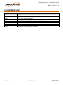
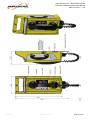
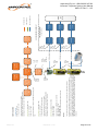
VOICECOM TELEPHONE SYSTEM User Manual MAG-157 Revision: 5 – January 2015 Designed and manufactured in Australia by Ampcontrol Pty Ltd Ampcontrol Pty Ltd – ABN 28 000 915 542 Voicecom Telephone System User Manual MAG-157 Rev 5 – 1/15 WARNING! CAUTION! This safety alert symbol identifies important safety messages in this manual and indicates a potential risk of injury or even death to personnel. When you see this symbol, be alert, your safety is involved, carefully read the message that follows, and inform other operators. This safety alert symbol identifies important information to be read in order to ensure the correct sequence of work and to avoid damage or even destruction of the equipment, and reduce any potential risk of injury or death to personnel. Supplementary information not directly affecting safety or damage to equipment. Carefully read the message that follows, and inform other relevant personnel. Information concerning possible impact on the environment and actions required for prevention and proper response. MAG-157 3/02/2015 10:19 Page 2 of 47 Ampcontrol Pty Ltd – ABN 28 000 915 542 Voicecom Telephone System User Manual MAG-157 Rev 5 – 1/15 Copyright Notice The Ampcontrol Intrinsically Safe Telephone System described in this document is the property of AMPCONTROL PTY LTD. It is furnished under a license agreement and is to be used only in accordance with the terms of the agreement. No part of the hardware or documentation may be reproduced, transmitted, transcribed, stored in a retrieval system, or translated into any language or computer language, in any form or by any means, without prior written permission of AMPCONTROL PTY LTD. Disclaimer While every effort has been made to assure the accuracy and clarity of this document, AMPCONTROL PTY LTD assumes no liability resulting from any omissions in this document, or from misuse of the information obtained herein. The information in this document has been carefully checked and is believed to be entirely reliable with all of the necessary information included. AMPCONTROL PTY LTD reserves the right to make changes to any products described herein to improve reliability, function, or design, and reserves the right to revise this document and make changes from time to time in content hereof with no obligation to notify any persons of revisions or changes. AMPCONTROL PTY LTD does not assume any liability arising out of the application or any use of any product or circuit described herein; neither does it convey license under its patent rights or the rights of others. Before You Begin We would like to take a moment to thank you for purchasing the Ampcontrol Intrinsically Safe Telephone System. WARNING! To become completely familiar with this equipment and to ensure correct operation, we strongly recommend that you take the time to read and thoroughly understand this user manual. Ampcontrol Contact Details 7 Billbrooke Close, Cameron Park, NSW, 2285 P +61 1300 267 373 | F +61 2 4903 4888 EMAIL: [email protected] WEB: www.ampcontrolgroup.com MAG-157 3/02/2015 10:19 Page 3 of 47 Ampcontrol Pty Ltd – ABN 28 000 915 542 Voicecom Telephone System User Manual MAG-157 Rev 5 – 1/15 TABLE OF CONTENTS 1 SAFETY AND OTHER WARNINGS ..................................................................5 1.1 Safe Use of Equipment ..............................................................................5 2 RECEIVING AND STORAGE ............................................................................6 2.1 Receiving ...................................................................................................6 2.2 Inspection ..................................................................................................6 2.3 Storage after Delivery ................................................................................6 2.4 Unpacking of Equipment ............................................................................6 3 INTRINSICALLY SAFE TELEPHONE SYSTEM OVERVIEW............................7 3.1 Interface Cabinet .......................................................................................8 3.2 Stand Alone Barrier ................................................................................. 11 4 SYSTEM COMPONENTS ............................................................................... 13 4.1 Auto-Auto Links ....................................................................................... 13 4.2 Intrinsically Safe Barrier ........................................................................... 14 4.3 Battery Charger ....................................................................................... 15 4.4 Voicecom Telephone ............................................................................... 16 4.5 Intrinsically Safe Indicator (ISI) ................................................................ 20 5 INSTALLATION ............................................................................................... 22 5.1 General Warnings .................................................................................... 22 5.2 Mandatory Installation Practices .............................................................. 23 5.3 Cable Considerations............................................................................... 23 6 SERVICE, MAINTENANCE & DISPOSAL ....................................................... 25 6.1 Equipment Service ................................................................................... 25 6.2 Equipment Maintenance .......................................................................... 26 6.3 Disposal ................................................................................................... 26 7 SPECIFICATIONS .......................................................................................... 27 7.1 Interface Cabinet and Batteries................................................................ 27 7.2 Barrier ...................................................................................................... 27 7.3 Voicecom Telephone ............................................................................... 28 7.4 Intrinsically Safe Indicator (ISI) ................................................................ 29 8 EQUIPMENT LIST .......................................................................................... 30 MAG-157 3/02/2015 10:19 Page 4 of 47 Ampcontrol Pty Ltd – ABN 28 000 915 542 Voicecom Telephone System User Manual MAG-157 Rev 5 – 1/15 1 SAFETY AND OTHER WARNINGS For safety reasons, the Intrinsically Safe Telephone System must be installed, operated and serviced only by competent personnel. Read and understand this instruction manual completely before installing, operating or servicing this equipment. Failure to install or operate this instrument in accordance with the instructions contained in this manual may create hazardous operating conditions. WARNING! To comply with the Conditions of Certification, ensure full serviceable life of the product, and avoid nullifying the warranty, it is essential to exercise great care with the installation, use and storage of the System components. Failure to comply with the Conditions of Certification may seriously compromise the integrity of the system and/or its components. The user must ensure that the “Conditions of Safe Use” outlined in the certificate are met or the certificate (and the I.S. rating) will not be valid. 1.1 Safe Use of Equipment The equipment supplied has been manufactured according to the state of the art, and designed to ensure a safe operation. The equipment may only be used within the design parameters. The instructions within this manual must be observed as an aid towards achieving maximum safety during operation. The owner/user is responsible for observing the following instructions: 1.1.1 Changes to Equipment Changes in the design and modifications to the equipment are not permitted. Unauthorised changes made to the hardware or operating firmware will void the manufacturer's warranty, and may compromise the integrity of the system into which it is installed and other connected equipment. 1.1.2 Equipment Knowledge Experience with, or understanding of, this equipment is essential for the safe installation and removal of the equipment. Therefore, in case of a question on how to safely proceed, contact Ampcontrol immediately. 1.1.3 Manual Handling Precautions have been taken to ensure all equipment is safe to handle and free from sharp edges. However care should always be taken when handling heavy enclosures and gloves should be worn. 1.1.4 Installation Correct operation and safety depend on the telephone system and associated equipment being installed correctly. Mechanical and or electrical installation and maintenance of plant and equipment must only be carried out by appropriately qualified personnel and must be tested thoroughly prior to operation. 1.1.5 Operation As safety depends on the I.S. Telephone System functioning correctly it is highly recommended that all safety functions of the system be periodically tested to ensure correct operation. MAG-157 3/02/2015 10:19 Page 5 of 47 Ampcontrol Pty Ltd – ABN 28 000 915 542 Voicecom Telephone System User Manual MAG-157 Rev 5 – 1/15 2 RECEIVING AND STORAGE 2.1 Receiving All possible precautions are taken to protect the equipment against damage or losses during shipment, however before accepting delivery, check all items against the packing list or bill of lading. If there are shortages or evidence of physical damage, notify Ampcontrol immediately. Notify Ampcontrol within 7 days (maximum) in case of shortages or discrepancies, according to the packing list. This action will help ensure a speedy resolution to any perceived problems. Keep a record of all claims and correspondence. Photographs are recommended. Where practicable do not remove protective covers prior to installation unless there are indications of damage. Boxes opened for inspection and inventory should be carefully repacked to ensure protection of the contents or else the parts should be packaged and stored in a safe place. Examine all packing boxes, wrappings and covers for items attached to them, especially if the wrappings are to be discarded. 2.2 Inspection Equipment that is found to be damaged or has been modified away from its published specification must not be used. Please contact Ampcontrol if the equipment is suspected to be different than that ordered or if it does not match the published specifications. 2.3 Storage after Delivery When the equipment is not to be installed immediately, proper storage is important to ensure protection of equipment and validity of warranty. All equipment should be stored indoors, preferably on shelves and protected from the elements. 2.4 Unpacking of Equipment The method of packing used will depend on the size and quantity of the equipment. The following cautions should be interpreted as appropriate. CAUTION! Take care when unpacking crates as the contents may have shifted during transport. The disposal of packaging materials, replaced parts, or components must comply with environmental restrictions without polluting the soil, air or water. Ensure that any timber and cardboard used as packaging is disposed of in a safe and environmentally responsible manner. Where possible, dispose of all waste products i.e. oils, metals, plastic and rubber products by using an approved recycling service centre. MAG-157 3/02/2015 10:19 Page 6 of 47 Ampcontrol Pty Ltd – ABN 28 000 915 542 Voicecom Telephone System User Manual MAG-157 Rev 5 – 1/15 3 INTRINSICALLY SAFE TELEPHONE SYSTEM OVERVIEW Ampcontrol manufactures a range of Intrinsically Safe (I.S.) telephones and interface equipment for underground mining applications, and for use in other Group I hazardous locations. The Telephone System is approved to AS/NZS 60079 and IEC 60079 for Intrinsic Safety Category Ex ia. This allows the telephone lines and telephones to be installed in Zone 0 hazardous locations. Interfacing equipment has the approval of the Australian Communications Authority (Suppliers Code No. N3463). The system is comprised of an interface cabinet, auto-auto link cards, isolation barriers and telephones. The system is compatible with standard 24 to 48V Analogue Telephone Line Extensions. The Voicecom Telephone has been designed to provide a user friendly communications solution. The enclosure is lightweight (<2kg) and IP67 rated to minimise damage to the unit. The telephone provides user customisation through programmable emergency call button, adjustable volume control and programmable quick-dial numbers. Key Features 1. Compatible with standard telephone PABX – note that the I.S. Telephone System requires a PBX to provide the signalling and control for calls. 2. Robust construction 3. Easy to install with flexibility to expand system 4. Optional Push-To-Talk for noisy environments There are two (2) configuration options depending on the number of I.S telephones you require. A standalone barrier can be used for a single telephone installation, or an interface cabinet can be used for applications where multiple telephones are required. MAG-157 3/02/2015 10:19 Page 7 of 47 Ampcontrol Pty Ltd – ABN 28 000 915 542 Voicecom Telephone System User Manual MAG-157 Rev 5 – 1/15 3.1 Interface Cabinet A single interface cabinet can connect up to 120 I.S. Telephone lines, providing all of the required signal conditioning, I.S. power limitation and battery backup. Note that the interface cabinet is not stand-alone; a PABX or SIP server is required to provide call initiation and handling. Discuss individual site requirements with Ampcontrol at the time of order. Figure 1: Ampcontrol Interface Cabinet The interface cabinet consists of: 1. A battery-backed power supply with sealed, maintenance free batteries, compliant with relevant ACMA regulations. A power supply of 240VAC 50Hz is required. See section 4.3 for details. Figure 2: Ampcontrol Interface Cabinet’s Rack Mounted AC/DC Battery Charger MAG-157 3/02/2015 10:19 Page 8 of 47 Ampcontrol Pty Ltd – ABN 28 000 915 542 Voicecom Telephone System User Manual MAG-157 Rev 5 – 1/15 2. Multiple 3RU shelf kits, each able to provide the signal conditioning and I.S. barriers for 15x telephone lines via the Auto-Auto Links and NB15AC barriers. See Sections 4.1 and 4.2 for details. Figure 3: Ampcontrol Interface 3RU Shelf Kit 3. Terminals and connecting hardware. This includes the I.S. Earth terminal block, which must be connected to the supply earth by a minimum 4mm2 earth conductor. I.S. Earth connection on site should be in accordance with AS/NZS60079.25 (Intrinsically safe electrical systems) and AS/NZS60079.14 (Electrical installations design, selection and erection). See Section 12.2.4 of Part 14 for details. MAG-157 3/02/2015 10:19 Page 9 of 47 Ampcontrol Pty Ltd – ABN 28 000 915 542 Voicecom Telephone System User Manual MAG-157 Rev 5 – 1/15 The capacity of the interface cabinet is determined by the number of shelf kits installed. For example, if 45 lines are required, 3 shelf kits will be installed (each has capacity for 15 lines). The maximum capacity of a single interface cabinet is 120 lines. It is limited to the number of shelf kits which may be installed, which is typically 8 for a standard-height cabinet. For additional lines, additional cabinets may be installed. See Figure 4 for a typical telephone system arrangement. SAFE AREA HAZARDOUS AREA ‘n’ 240VAC SUPPLY 16A CB 1 2W ANALOGUE EXTN PORT PABX 2W I.S. LINE VOICECOM PHONE I.S. RACK ‘n’ ‘n’ CHASSIS EARTH I.S. EARTH Figure 4: Interface Cabinet Telephone System Note that the I.S. Telephone System requires a site PBX for call functionality. Ampcontrol is able to provide both traditional digital and VoIP PBX solutions; contact Customer Service for enquiries. MAG-157 3/02/2015 10:19 Page 10 of 47 Ampcontrol Pty Ltd – ABN 28 000 915 542 Voicecom Telephone System User Manual MAG-157 Rev 5 – 1/15 3.2 Stand Alone Barrier This unit comprises of a single Auto-Auto Link Safety Barrier and DC power supply. A power supply of 240VAC 50Hz is required. This configuration allows for only one circuit (that is, one telephone) with no battery backup. Figure 5: Single Telephone Stand Alone Barrier MAG-157 3/02/2015 10:19 Page 11 of 47 Ampcontrol Pty Ltd – ABN 28 000 915 542 Voicecom Telephone System User Manual MAG-157 Rev 5 – 1/15 Figure 6 shows the arrangement for a single telephone circuit using a stand-alone barrier. SAFE AREA HAZARDOUS AREA 240VAC SUPPLY + EARTH FROM 10A G.P.O. 2W ANALOGUE EXTN PORT PABX 2W I.S. LINE STAND-ALONE BARRIER UNIT VOICECOM PHONE I.S. EARTH Figure 6: Single Telephone System Note that the I.S. Telephone System requires a site PBX for call functionality. Ampcontrol is able to provide both traditional digital and VoIP PBX solutions; contact Customer Service for enquiries. I.S. Earth connection on site should be in accordance with AS/NZS60079.25 (Intrinsically safe electrical systems) and AS/NZS60079.14 (Electrical installations design, selection and erection). See Section 12.2.4 of Part 14 for details. Clear provision is made for connection of I.S. Earth in both standalone and interface cabinet arrangements. MAG-157 3/02/2015 10:19 Page 12 of 47 Ampcontrol Pty Ltd – ABN 28 000 915 542 Voicecom Telephone System User Manual MAG-157 Rev 5 – 1/15 4 SYSTEM COMPONENTS 4.1 Auto-Auto Links An Auto-Auto Link is a modular plug-in printed circuit card and is required for each telephone extension. The Auto-Auto Link provides signal isolation between the safe area telephone equipment and telephone line and the telephone installed in the hazardous area. The modular printed circuit board plugs in to a standard 19" Rack Eurocard Shelf Kit that accommodates fifteen (15) Auto-Auto Links. 4.1.1 Brief Description The Auto-Auto Link removes the speech and ring signal from the incoming 24 to 48 Volt analogue telephone line. The speech is re-impressed on the telephone lines to the I.S telephones using the 24VDC supply from the system batteries. Any incoming ring signal is converted to a simple line voltage reversal which appears on the I.S telephone lines. The I.S telephone recognises this line reversal as a ring signal and emits an audible tone to indicate an incoming call. The off hook signal from the I.S telephones is also detected by the Auto-Auto Link PCB and relayed to the PABX or PSTN line or IP server where ATA’s are used. All signals to and from the I.S telephone lines are via the approved barrier which is mounted on the AutoAuto Link Shelf kit. The combination of the Auto-Auto Link circuit and the approved barrier creates total electrical isolation and full safety limiting between the PABX/PSTN/IP SERVER telephone lines in the safe area and the I.S telephone lines in the hazardous area. 4.1.2 Operation The Auto-Auto Link PCB is factory pre-set and requires no field adjustments. MAG-157 3/02/2015 10:19 Page 13 of 47 Ampcontrol Pty Ltd – ABN 28 000 915 542 Voicecom Telephone System User Manual MAG-157 Rev 5 – 1/15 4.2 Intrinsically Safe Barrier The NB15AC is an intrinsically safe Zener barrier. The barrier is designed to be installed in a safe area, providing an intrinsically safe output which can be used in Group I or IIC hazardous areas, as per certification ANZEx 12.3009X. The barrier consists of a combination of Zener diodes, power limiting resistors and fuses. These components limit any hazardous power signals through the barrier to a safe level before entering a hazardous area. The barrier provides isolation between the telephone equipment located in a safe area and the telephone installed in the hazardous area. The NB15AC barrier configuration used in the IS Telephone System is Configuration B. MAG-157 3/02/2015 10:19 Page 14 of 47 Ampcontrol Pty Ltd – ABN 28 000 915 542 Voicecom Telephone System User Manual MAG-157 Rev 5 – 1/15 4.3 Battery Charger The AC/DC Battery Charger is rack mounted and is installed in the top section of the Interface Cabinet. The Battery Charger is connected directly to the standby batteries and load in a float charge arrangement. Input supply to the standard Battery Charger is 240V ± 5% and should be protected by a 16A circuit breaker. Output Voltage is 27.6VDC and the Output Current is 5A. The front fascia of the Battery Charger contains a voltmeter that can be selected to read the battery or load voltage. An ammeter is provided for load current and five (5) LEDs indicate the status of the charger. Figure 7: Rack Mounted AC/DC Battery Charger 4.3.1 LED Indication The LED lights indicate the following operating conditions of the Battery Charger: DC OK BATT OK BATT ON-LINE BATT STATUS OVER TEMPERATURE 4.3.2 Standby Batteries The Ampere Hour rating of the 24VDC standby battery is dependent on the number of Auto-Auto Links installed and the time telephone communications must be maintained during a power failure. 12V Sealed Gel (no maintenance) batteries are supplied in a nominal 40AHr capacity. The capacity of the battery bank can be increased as required. Discuss individual site requirements with Ampcontrol at the time of order. MAG-157 3/02/2015 10:19 Page 15 of 47 Ampcontrol Pty Ltd – ABN 28 000 915 542 Voicecom Telephone System User Manual MAG-157 Rev 5 – 1/15 4.4 Voicecom Telephone The Ampcontrol Voicecom Telephone has been designed for use in the coal mining industry. The telephone is Ex ia certified for use in Group I hazardous areas, and provides a reliable solution to suit harsh underground environments. The enclosure is lightweight (<2kg) and IP67 rated. Easy installation Field-replaceable handset IEC certified to Ex ia: IECEx MSC 14.0019X Programmable quick-dial numbers Optional Push-To-Talk (PTT) for noisy environments DTMF and Pulse dialling options Figure 8: Voicecom Telephone 4.4.1 Brief Description The Voicecom Telephone has been designed to provide a user friendly communications solution. The lightweight design is coupled with an integrated carry handle to allow for easy transport and installation. The spring retained handset provides security and reduces the risk of damage, while providing improved portability of the unit. Should the handset be damaged, it may be replaced without the need to remove the telephone from the field. A 24VDC supply is provided from batteries within the Interface Cabinet to the telephone unit, no battery is required. Up to three (3) Voicecom telephones can be connected in a party line configuration, depending on phone line length and cross-section. MAG-157 3/02/2015 10:19 Page 16 of 47 Ampcontrol Pty Ltd – ABN 28 000 915 542 Voicecom Telephone System User Manual MAG-157 Rev 5 – 1/15 4.4.2 Mounting and Installation The carry handle is provided with mounting detail to allow for installation of the unit to 24mm rib bolts, or using M5 mounting screws. Mounting loops are provided for general use which can be used for extra mounting or for attaching additional phone information (for example, a phone list). An integrated terminal compartment allows for simple connection and can be accessed using a single retained hex nut. The cable is terminated through pre-tapped M16 gland entries into spring-cage terminals. Figure 9: Voicecom Telephone’s Terminal Compartment Power is to be supplied by a suitably rated I.S. barrier – the NB15AC, see Section 4.2. Connection to be terminated to the LINE IN terminals in the termination compartment. Connectors labelled FACTORY USE ONLY are not to be used for field termination. Incoming cable is to be connected via a suitably rated cable gland, and the termination compartment cover to be replaced in service. If an additional device is to be connected to the same line, the LINE OUT terminals may be used and the outgoing cable connected via a suitably rated cable gland. MAG-157 3/02/2015 10:19 Page 17 of 47 Ampcontrol Pty Ltd – ABN 28 000 915 542 Voicecom Telephone System User Manual MAG-157 Rev 5 – 1/15 4.4.3 Call Operation The Voicecom Telephone is used in the same manner as a normal telephone. Site procedures will apply to any special cases such as emergencies. Audio and visual notification is provided to signal an incoming call. Adjustable volume control allows configuration for a particular applications. If the handset remains off-hook for more than 30 minutes, the telephone will automatically hang up. A programmable emergency call button (programmed by default to 555) is provided. To make an emergency call, press the Emergency Call button (!) twice within a two second window. To dial a stored quick-dial number, the user presses Q, followed by the quick-dial entry required (1-9). 4.4.4 Programmable features The Voicecom Telephone has a number of user-accessible programmable features. These are: Quick-dial number entries on digits 1 through to 9 Adjustable DTMF levels (to combat signal losses on long telephone lines) Selectable tone or pulse dialling To program a quick-dial number: 1. Pick up handset 2. Dial * # (beep will be heard) 3. Dial 0 0 [key to program]. E.g. 0 0 1 for fast dial entry on key 1, or 0 0 EMERGENCY to change the Emergency dial string 4. Dial * # 5. Enter phone number 6. Dial # (2 beeps will be heard to finish) 7. Replace handset For example, to dial ‘0249034800’ into quick dial 1: (pick up handset) * # (beep) 0 0 1 * # 0 2 4 9 0 3 4 8 0 0 # (two beeps) (replace handset) MAG-157 3/02/2015 10:19 Page 18 of 47 Ampcontrol Pty Ltd – ABN 28 000 915 542 Voicecom Telephone System User Manual MAG-157 Rev 5 – 1/15 To program other phone settings: 1. Pick up handset 2. Dial * # (beep will be heard) 3. Dial [dial string] for setting to be adjusted, e.g. 1 0 2 to change dial type 4. Dial * # 5. Dial [dial string] for option selected, e.g. 0 1 for tone dialling 6. Dial # (2 beeps will be heard to finish) 7. Replace handset Setting Desciption DTMF Levels Dialling Type Options Dial String Desciption +6Db on high freq DTMF 101 All DTMF levels equal Tone 102 Pulse Dial String 01 02 01 02 For example, to set pulse dialling: (pick up handset) * # (beep) 1 0 2 * # 0 2 # (two beeps) (replace handset) Any mistake during programming will result in three beeps. The user must hang up to start again. 4.4.5 Certification Details IECEx MSC 14.0019X Ex ia I -20°C < Tamb < 60°C IP67 Electrical Parameters on Line In terminals: Ui = 30V Ii = 200mA Pi = 1.3W Ci = neg Li = neg See Conditions of Safe Use on certificate in appendix. The device conforms with IEC60079.11, section 6.3.13. All exposed non-metallic surfaces >100cm2 have a surface resistance complying with IEC60079.0, section 7.4.2. The Voicecom Telephone is suitable for use in Group I environments, with a temperature range -20°C to 60°C. See the appendix to this user manual for a copy of certificate IECEx MSC 14.0019X MAG-157 3/02/2015 10:19 Page 19 of 47 Ampcontrol Pty Ltd – ABN 28 000 915 542 Voicecom Telephone System User Manual MAG-157 Rev 5 – 1/15 4.5 Intrinsically Safe Indicator (ISI) The Ampcontrol Intrinsically Safe Indicator (ISI) is an accessory for the I.S. Telephone System. It can be connected to the same line as a Voicecom Telephone, and is used to provide an audible and visual alert to personnel in the area of an incoming ring. A typical installation for the ISI is in a roadway where a telephone is installed in an adjacent cut-through. When the telephone rings, the alert will be out of line-of-sight of operators. The ISI provides a secondary means of alert so that the call can be answered. Figure 10: Intrinsically Safe Indicator (ISI) Unit 4.5.1 Installation The ISI can be mounted to any type of enclosure via a threaded mounting sleeve, nylon washer and nut. The nylon washer provides ingress protection into the enclosure, and the ISI itself is encapsulated for environmental sealing. The integral wires of the ISI will be connected to terminals inside an enclosure having a minimum protection rating of IP54. Power is to be supplied by a suitably rated I.S. barrier – the NB15AC, see Section 4.2. The ISI has flying leads for wiring into terminals. It is possible to select audible alert, visual alert or both audible and visual alert. MAG-157 3/02/2015 10:19 Page 20 of 47 Ampcontrol Pty Ltd – ABN 28 000 915 542 Voicecom Telephone System User Manual MAG-157 Rev 5 – 1/15 4.5.2 Certification Details IECEx MSC 14.0019X Ex ia I -20°C < Tamb < 60°C IP67 Electrical Parameters on Line In terminals: Ui = 30V Ii = 200mA Pi = 1.3W Ci = neg Li = neg See Conditions of Safe Use on certificate in appendix. The device conforms with IEC60079.11, section 6.3.13. There are no user serviceable parts. For repairs or decommissioning, return to the manufacturer. The ISI is suitable for use in Group I environments, with a temperature range -20°C to 60°C. See the appendix to this user manual for a copy of certificate IECEx MSC 14.0019X. MAG-157 3/02/2015 10:19 Page 21 of 47 Ampcontrol Pty Ltd – ABN 28 000 915 542 Voicecom Telephone System User Manual MAG-157 Rev 5 – 1/15 5 INSTALLATION 5.1 General Warnings These instructions have been designed to assist users of the Intrinsically Safe Telephone System with installation. Before the telephone can be installed, there are a number of things that need to be considered and understood to prevent incorrect or unsafe operation of the telephone or the system into which it is installed. Along with relevant competence, and an understanding of the target application, the following points should be considered: 5.1.1 Ensure that the information provided in this user manual is fully understood. It is extremely important that the limitations and functionality of the I.S Telephone System are understood to prevent incorrect installation and use from creating a potentially dangerous risk. If in doubt as to the nature of the limitations or their implication, consult a competent authority such as a supervisor or Ampcontrol technical representative. 5.1.2 Ensure that the application into which the telephone is being installed has been properly defined, designed and approved. Any critical communications system needs to be properly designed and implemented. Such a system must be the result of structured risk analysis with the outcomes used to define the system requirements. These requirements, in turn, will guide the choice of equipment needed to implement the system. Understanding the needs of the system will ensure proper selection of equipment. 5.1.3 Ensure that the I.S Telephone System will properly perform the required functions within the system design. It is important to understand how the telephone is intended to interact with other equipment within a system. For safe and reliable use, it is crucial that neither the system’s logical operation nor its signalling be compromised by incompatibilities with connected equipment. 5.1.4 Modifications of any form to the I.S Telephone are prohibited. The telephone as supplied has been designed and manufactured to comply with the applicable standards. If modifications of any form are made to the telephone, the equipment may no longer be fit for use. If any modifications or damage to the telephone is evident, do not use the equipment and contact Ampcontrol for advice. MAG-157 3/02/2015 10:19 Page 22 of 47 Ampcontrol Pty Ltd – ABN 28 000 915 542 Voicecom Telephone System User Manual MAG-157 Rev 5 – 1/15 5.2 Mandatory Installation Practices The following information must be adhered to when installing the I.S Telephone System. Failure to adhere to this information may give rise to unsafe operation. Using the telephone in a manner that exceeds its electrical, functional or physical specifications, or in a way that is contrary to its operating restrictions, may create risks to personnel and/or equipment resulting in injury or death. 1. Ensure that the I.S. Earth connection is correctly installed as per AS/NZS 60079.14. 2. The telephone must be powered by an Ampcontrol supplied Interface Cabinet or Stand-Alone barrier. 3. The installation of the telephone must be carried out by suitably trained and qualified personnel. 4. Certification and identification labels fixed to the telephone must not be damaged, removed or covered before, during or after installation. 5. The supply to an installed I.S. Rack must be protected by a 16A circuit breaker. Any installed Stand-Alone barriers must be supplied from a standard 10A G.P.O. 6. The installation is to be in accordance with the relevant installation Standards/Codes of Practice. 7. Modifications must not be made to any part of the telephone. As supplied, the unit is built to, and complies with the relevant standards. Modifications to its construction will render the unit incompatible with its certification. 8. Complete and accurate records of the installation must be kept as part of the site installation. 5.3 Cable Considerations 5.3.1 Safe Area Telephone Lines A standard multicore telephone cable connects the Interface Cabinet Safe Area Krone Connection block to the PABX. Connections to the cabinet from the PBX are affected on these Krone connections. 5.3.2 Hazardous Area Cable Selection Ampcontrol can supply telephone cable suitable for deployment with the I.S telephone system. Where cables are to be sourced elsewhere, Ampcontrol recommends the use of AS/ACIF S008, AS/NZS 2381.7 compliant cable to maximise audio performance. Ampcontrol recommends the use of 0.90mm cable to minimise voltage drop to the telephone. Individual shielding of each pair is required by AS/NZS 2381, and is recommended to mitigate electrical interference from other systems. At the user’s discretion, Type B cable in accordance with AS/NZS 60079 may be used if non-individually screened cable is required. 5.3.3 Hazardous Area Cable Installation The cable connecting the Auto-Auto Link Barrier to the I.S telephone, through the hazardous area, must not exceed the parameters listed in the Certificate of Conformity (ANZEx 06.3042X). The telephone system must also be compliant with the requirements of AS/ACIF S008 - Requirements for Customer Cabling Products. The cable should be installed such that the impedance is minimised, and to reduce the effect of noise on the system the cable shielding should be earthed at the Head End only. It is important that the following installation practice be followed: Shields earthed to the chassis earth in one location only, at the I.S phone rack. Shields not connected together except for the point of earth connection Shields continuous all the way to the telephone It is helpful to treat the shield on an individually screened telephone pair as the third conductor for each MAG-157 3/02/2015 10:19 Page 23 of 47 Ampcontrol Pty Ltd – ABN 28 000 915 542 Voicecom Telephone System User Manual MAG-157 Rev 5 – 1/15 telephone service; it is to be properly carried through to the telephone and not cross connected with any other signal. Unused cores must be earthed. This earth should come from the head-end equipment earth to minimise interference. This may be achieved by carrying an earth signal from the head end on a pair of conductors in the cable bundle. It is the responsibility of the end user to audit the telephone system installation to ensure compliance with I.S. requirements. CAUTION! For a cable containing Intrinsically Safe circuits, non-I.S circuits must NOT be run in the same cable. MAG-157 3/02/2015 10:19 Page 24 of 47 Ampcontrol Pty Ltd – ABN 28 000 915 542 Voicecom Telephone System User Manual MAG-157 Rev 5 – 1/15 6 SERVICE, MAINTENANCE & DISPOSAL 6.1 Equipment Service If a handset is damaged, a replacement may be obtained from the manufacturer. See the Conditions of Safe Use for details. Otherwise, there are no user serviceable parts. For repairs or decommissioning, return to the manufacturer. A number of external system based checks should however be completed on a regular basis. These ‘routine inspections’ must be carried out by suitably trained people with knowledge of the telephone and the systems into which it is fitted. Routine inspections may take the form of either visual-only checks, or visual and ‘hands-on’ checks. 6.1.1 Visual Only Inspections A basic visual inspection focuses on looking at the installation for signs of physical damage, water or dust ingress and the condition of cables and labels. Observations would typically be: 1. Check that equipment enclosures, cable trays, conduits, etc. are in good order with no physical damage. 2. Check that connected cables are free from cuts, abrasions and obvious signs of damage. Cable restraints are in good order and correctly fitted. 3. Check that labels on equipment, wall boxes and cables are present and in good condition (especially certification labels). 4. Check that no modifications have been carried out to installed equipment. 6.1.2 Hands-On (Detailed) Inspections A more detailed inspection would include all of the elements of a visual inspection, plus some checks that cover the integrity of connections, fixtures and fittings. In addition to basic visual observations, more detailed integrity checks would involve: 5. Verify that equipment housings, wall boxes and other mechanical fixtures are secured in place. This includes terminal box lids, tightness of cable glands, integrity of wall-box mountings, security of equipment fixing to walls/DIN rails etc. 6. Verify all electrical connections are secure with no loose screw terminals or DIN rail terminals not fitted to rails etc. Particular attention is to be paid to the I.S. Earth connections. 7. Verify operation of the telephone by making and receiving calls; confirm that voice communication is clear. 8. Refer to site procedures regarding the testing of the emergency call functionality. 9. For interface cabinets equipped with battery chargers with diagnostic capability, regular (minimum 12 monthly) checks on battery health are recommended. Otherwise, it is recommended that the batteries be replaced every five years. MAG-157 3/02/2015 10:19 Page 25 of 47 Ampcontrol Pty Ltd – ABN 28 000 915 542 Voicecom Telephone System User Manual MAG-157 Rev 5 – 1/15 6.2 Equipment Maintenance WARNING! The Intrinsically Safe Telephone System has no user-serviceable parts. All repairs must be carried out by Ampcontrol only. If a fault develops, return to Ampcontrol for repair. It is essential that no attempt be made to repair the telephone as any attempt to dismantle or repair the telephone can seriously compromise the safety of the unit. 6.3 Disposal The electronic equipment discussed in this manual must not be treated as general waste. By ensuring that this product is disposed of correctly you will be helping to prevent potentially negative consequences for the environment which could otherwise be caused by incorrect waste handling of this product. MAG-157 3/02/2015 10:19 Page 26 of 47 Ampcontrol Pty Ltd – ABN 28 000 915 542 Voicecom Telephone System User Manual MAG-157 Rev 5 – 1/15 7 SPECIFICATIONS 7.1 Interface Cabinet and Batteries General Input Voltage Output Voltage to Batteries Output Current Cable Requirements 240VAC ± 5% at full output current, 50Hz 27.6VDC (24VDC) 5A Refer to Section 5 for details 7.2 Barrier General Certification I.S. Parameters Connection Method Configuration - B MAG-157 ANZEx 12.3009X Maximum V & I Uo Io 30V 66mA Group IIC (Maximum) Co Lo Lo/Ro 44nF 40µH 4µH/Ω 3/02/2015 10:19 Group I (Maximum) Co Lo Lo/Ro 1.5µF 2.0mH 15µH/Ω Page 27 of 47 Ampcontrol Pty Ltd – ABN 28 000 915 542 Voicecom Telephone System User Manual MAG-157 Rev 5 – 1/15 7.3 Voicecom Telephone General Certification Operating Current Ringing Volume Operating Temperature Humidity IECEx MSC 14.0019X 3.5 - 9.5mA 85dB @ 3’ -20 - 60°C 0 - 90%, non-condensing I.S. Parameters Maximum Input Voltage Maximum Input Current Maximum Input Power Maximum Internal Capacitance Maximum Internal Inductance Outputs Keypad Indication Compliances Mechanical Dimensions (HxWxD) Ingress Protection MAG-157 Ui Ii Pi Ci Li 30V 200mA 1.3W Negligible Negligible Dimple on “5” and “Emergency” buttons Yellow Ringing LEDs IEC 60079.0 IEC 60079.11 ETR 051 ITU-T P350 ITU-T E161 404x145x102mm IP67 3/02/2015 10:19 Page 28 of 47 Ampcontrol Pty Ltd – ABN 28 000 915 542 Voicecom Telephone System User Manual MAG-157 Rev 5 – 1/15 7.4 Intrinsically Safe Indicator (ISI) General Certification Operating Current Ringing Volume Operating Temperature Humidity IECEx MSC 14.0019X 5mA 85dB @ 3’ -20 - 60°C 0 - 90%, non-condensing I.S. Parameters Maximum Input Voltage Maximum Input Current Maximum Input Power Maximum Internal Capacitance Maximum Internal Inductance Mechanical Dimensions (HxWxD) Ingress Protection MAG-157 Ui Ii Pi Ci Li 30V 200mA 1.3W Negligible Negligible 45x115x61mm IP55 to be mounted on a minimum IP54 enclosure 3/02/2015 10:19 Page 29 of 47 Ampcontrol Pty Ltd – ABN 28 000 915 542 Voicecom Telephone System User Manual MAG-157 Rev 5 – 1/15 8 EQUIPMENT LIST Part Number 169890 169893 142036 117675 170364 170365 172639 173203 MAG-157 Description TELEPHONE VOICECOM WITH NORMAL HANDSET TELEPHONE VOICECOM WITH PTT HANDSET AUTO AUTO LINK V6 NO BARRIER BARRIER NB15AC REPLACEMENT HANDSET FOR VOICECOM TELEPHONE REPLACEMENT PTT HANDSET FOR VOICECOM TELEPHONE REPLACEMENT TERMINAL COVER AND O-RINGS MODULE TELEPHONE VCOM A/V ALARM ISI 3/02/2015 10:19 Page 30 of 47 Ampcontrol Pty Ltd – ABN 28 000 915 542 Voicecom Telephone System User Manual MAG-157 Rev 5 – 1/15 APPENDIX A DRAWINGS MAG-157 3/02/2015 10:19 Page 31 of 47 Ampcontrol Pty Ltd – ABN 28 000 915 542 Voicecom Telephone System User Manual MAG-157 Rev 5 – 1/15 MAG-157 3/02/2015 10:19 Page 32 of 47 MAG-157 3/02/2015 10:19 Installation to be undertaken by “competent persons” as defined in AS/NZS/IEC 2381.7/ 60079.14. Installation must comply with any site specific requirements or regulations as well as hazardous area installation standards including but not limited to: AS/NZS/IEC 2381.1, 60079.1, 2381.7, 60079.14 and 4871. Due consideration shall also be given to any special conditions of safe use listed in the certificates of components (such as ISI to be installed on an IP54 rated enclosure). Ui: 12.6V Ii: 100mA Ci: 1.6uF Li: neg Uo: 12.6V Io: 88mA Co: 1.8uF Lo: 38mH L2 Optional Voicecom VIA L1 I.S. Telephone Line Ui: 30V Ii: 200mA Ci: neg Li: neg I.S. Telephone Line Ui: 30V Ii: 200mA Ci: neg Li: neg Uo: 30V Io: 66mA Co: 1.5uF Lo: 2mH L/R: 15uH/R Uo: 30V Io: 66mA Co: 1.5uF Lo: 2mH L/R: 15uH/R Uo: 30V Io: 66mA Co: 1.5uF Lo: 2mH L/R: 15uH/R Voicecom Amplifier #2 I.S. Telephone Line Uo: 12.6V Io: 97.5mA Co: 30uF Lo: 49mH L/R: 1.52mH/R Ui: 30V Ii: N/A Ci: neg Li: neg Voicecom Amplifier #1 I.S. Power Supply Voicecom Controller VCA I.S. Power Supply Voicecom Amplifier #1 Cable values shown above are typical values only, and are provided as indicative. Notes Typical cable has L = 0.8mH/km and C = 50nF/km 38mH ÷ 0.8mH/km = 47.5km 200nF ÷ 50nF/km = 4km Therefore maximum distance between VCA and VTA = 4km VCA-VTA Audio (where VIA is omitted) CCABLE = Co – Ci = 200nF LCABLE = Lo – Li = 38mH Typical cable has L/R < 15uH and C = 50nF/km L/R of barrier = 15uH, so cable not limited by inductance Cable length > 500km based on 28.4uF ÷ 50nF/km VIA-VTA Audio (where VIA is used) CCABLE = Co – Ci = 28.4uF Li = neg, so L/R may be used for assessment VIA must be installed in a safe area. Recommend co-locating with VCA. VCA-VIA Audio (where VIA is used) CCABLE = Co – Ci = 1.8uF LCABLE = Lo – Li = 38mH Voicecom Amplifier #31 Typical cable has L/R < 15uH and C = 50nF/km L/R of barrier = 15uH, so cable not limited by inductance Cable length = 30km based on 1.5uF ÷ 50nF/km I.S. Telephone Line CCABLE = Co – Ci = 1.5uF Li = neg, so L/R may be used Cable Calculations NB15AC NB15AC NB15AC Auto/Auto Card Auto/Auto Card Auto/Auto Card I.S. Telephone Rack SURFACE EQUIPMENT PBX or ATA 2-wire I.S. Telephone 2-wire I.S. Audio I.S. Voicecom Line UNDERGROUND EQUIPMENT Voicecom Amplifier #31 Ampcontrol Pty Ltd – ABN 28 000 915 542 Voicecom Telephone System User Manual MAG-157 Rev 5 – 1/15 Page 33 of 47 Ampcontrol Pty Ltd – ABN 28 000 915 542 Voicecom Telephone System User Manual MAG-157 Rev 5 – 1/15 APPENDIX B CERTIFICATIONS MAG-157 3/02/2015 10:19 Page 34 of 47 Ampcontrol Pty Ltd – ABN 28 000 915 542 Voicecom Telephone System User Manual MAG-157 Rev 5 – 1/15 MAG-157 3/02/2015 10:19 Page 35 of 47 Ampcontrol Pty Ltd – ABN 28 000 915 542 Voicecom Telephone System User Manual MAG-157 Rev 5 – 1/15 MAG-157 3/02/2015 10:19 Page 36 of 47 Ampcontrol Pty Ltd – ABN 28 000 915 542 Voicecom Telephone System User Manual MAG-157 Rev 5 – 1/15 MAG-157 3/02/2015 10:19 Page 37 of 47 Ampcontrol Pty Ltd – ABN 28 000 915 542 Voicecom Telephone System User Manual MAG-157 Rev 5 – 1/15 MAG-157 3/02/2015 10:19 Page 38 of 47 Ampcontrol Pty Ltd – ABN 28 000 915 542 Voicecom Telephone System User Manual MAG-157 Rev 5 – 1/15 MAG-157 3/02/2015 10:19 Page 39 of 47 Ampcontrol Pty Ltd – ABN 28 000 915 542 Voicecom Telephone System User Manual MAG-157 Rev 5 – 1/15 MAG-157 3/02/2015 10:19 Page 40 of 47 Ampcontrol Pty Ltd – ABN 28 000 915 542 Voicecom Telephone System User Manual MAG-157 Rev 5 – 1/15 MAG-157 3/02/2015 10:19 Page 41 of 47 Ampcontrol Pty Ltd – ABN 28 000 915 542 Voicecom Telephone System User Manual MAG-157 Rev 5 – 1/15 MAG-157 3/02/2015 10:19 Page 42 of 47 Ampcontrol Pty Ltd – ABN 28 000 915 542 Voicecom Telephone System User Manual MAG-157 Rev 5 – 1/15 MAG-157 3/02/2015 10:19 Page 43 of 47 Ampcontrol Pty Ltd – ABN 28 000 915 542 Voicecom Telephone System User Manual MAG-157 Rev 5 – 1/15 MAG-157 3/02/2015 10:19 Page 44 of 47 Ampcontrol Pty Ltd – ABN 28 000 915 542 Voicecom Telephone System User Manual MAG-157 Rev 5 – 1/15 MAG-157 3/02/2015 10:19 Page 45 of 47 Ampcontrol Pty Ltd – ABN 28 000 915 542 Voicecom Telephone System User Manual MAG-157 Rev 5 – 1/15 MAG-157 3/02/2015 10:19 Page 46 of 47 Ampcontrol Pty Ltd – ABN 28 000 915 542 Voicecom Telephone System User Manual MAG-157 Rev 5 – 1/15 MAG-157 3/02/2015 10:19 Page 47 of 47