1
INSTALLATION GUIDE
Ceiling TV Mount
MHP-52
Max Load Capacity: 125 lbs (57kg)
Note: Read entire instruction sheet before you start installation and assembly.
WARNING
Be sure to read this entire manual thoroughly and you fully understand all the instructions and warning before
attempting to begin your installation.
This product should only be installed by someone who has a basic knowledge of buiding construction,in stallations
and fully understands these instructions.
Make sure that the supporting surface will safely support the combined load of the mount, the display and all
attached hardware and components.
The maximum load capacity is 125 pounds.
If mounting to a wall of wood stud construction, be sure that mounting bolts are anchored to the center of the
studs.
Always have someone assist you to lift and position your equipment.
Tighten screws and bolts firmly, but do not over tighten. Over tightening can damage the items and greatly reduce
their ability to hold. Please refer to suggested torque values where applicable in these instructions.
Tools Needed for Assembly
stud finder ("edge to edge" stud finder is recommended)
phillips screwdriver
drill with 1/4", 3/8", and 5/32" drill bits
Table of Contents
Parts List .............................................................................................................................................................................. 3
Installation to Wood Joist Ceiling .......................................................................................................................................... 4
Installation to Concrete Ceiling ............................................................................................................................................. 5
Installation of Extension Column ........................................................................................................................................... 6
Mounting the Assembly Adapter plate to screen ........................................................................................ ......................... 7
Attach Assembly Adapter plate to Assembly Arm .................. .................................................................... ......................... 8
Tilt Adjustment and cord Cord Coves and Wire Managment ............................................................................................. 8
2 of 8
Before you b egin, make sure all parts shown are included
with your product.
Parts may appear slightly different than illustrated.
Parts List
Description
A
nonskid nut
4
A
B
B
C
D
D
Hexagon fillister head screw
4
8
8
2
8
8
8
8
8
8
E
E
F
F
G
H
H
I
J
K
L
L
M
N
N
philips pan head screw
washer
allen cap screw
philips pan head screw
philips pan head screw
philips pan head screw
philips pan head screw
philips pan head screw
philips pan head screw
philips pan head screw
8
8
1
1
I
M
N
G
F
J
C
M6
M5
M8x50
Ø8.2xØ16x2.0
M8x50
4
4
4
E
B
B
25.65x25.65x2.5
Ø12.7xØ6.0x12.7
Ø19xØ8.2x19.6
8
allen wrench
allen wrench
concrete anchor
washer
hex bolt screw
A
Ø8.2xØ1.5x16
M8x15
8
allen cap screw
square spacer
spacer
spacer
H
Ø6xØ13x1.2
M4x3
M4x16
M4x30
M5x16
M5x30
M6x16
M6x30
M8x45
8
8
washer
D
A
M8x60
M6x12
K
plate (x1)
H
L
CC (x1)
DD (x1)
AA (x1) BB (x1)
3 of 8
adapter plate
EE (x2)
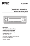
Installation to Wood Joist Finished Ceilings,
Exposed Wood Joists, or Wood Beam Ceilings
Drill four 1/4" (6 mm) dia. holes to a minimum
depth of 1.57" (40 mm). Attach ceiling plate
with four hex bolt screws M8x50 ( N ) as shown
using 1/2" (13mm) socket wrench.Tighten wood
screws ( N ).so ceiling plate is firmly attached.
WARNING
Tighten wood screws so that ceiling plate is firmly
attached, but do not overtighten. Overtightening can
damage the screws, greatly reducing their holding
power.
Make sure that mounting screws are anchored into the
center of the joist. The use of an "edge to edge" stud
finder is highly recommended.
N
4 of 8
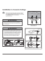
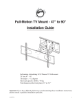
Installation to Concrete Ceilings
Drill four 3/8" (10 mm) dia. holes to a minimum depth of
1.57" (40 mm). Attach ceiling plate using four concrete
anchors (M ) and M8x50 hex bolt screws ( N ) as shown
in Illustration A and 1, 2, and 3 (below).
Tighten all fasteners.
M
WARNING
Tighten wood screws firmly, but do not overtighten.
Overtightening can damage the bolt, greatly reducing
its holding power.
N
Illustration A
WARNING
1
Concrete anchors are not intended for attachment to
concrete wall covered with a layer of plaster, drywall,
or other finishing material. If mounting to concrete wall
covered with plaster/drywall is unavoidable, plaster/
drywall (up to 5/8" thick) must be counterbored as
shown below. If plaster/drywall is thicker than 5/8",
custom fasteners must be supplied by installer.
CUTAWAY VIEW
INCORRECT
metal
bracket
concrete
M
Drill hole and insert anchor
2
N
CORRECT
metal
bracket
concrete
ceiling
concrete
M
Place ceiling plate over anchor and secure with screw
3
plaster/
dry wall
plaster/
dry wall
N
M
After repeating step one tighten all fasteners
5 of 8
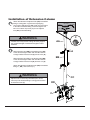
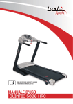
Installation of Extension Column
Attach threaded end of adjuster tube (AA) to threaded
fitting in ceiling plate . Tighten securely aligning
slot in end of adjuster tube (AA ) with one of the holes
in the side of threaded fitting. Insert and tighten one
M4 x 3 mm allen cap screw ( C) to lock adjuster
tube (AA) to threaded fitting.
C
WARNING
AA
Installer must verify that the ceiling will safely support
the combined weight of all attached equipment and
hardware.
A
Slide extension pipe (BB) over adjuster tube ( AA)
to the desired height. Attach with two M8 x 60 mm
hexagon fillister head screws (A ) and lock nut ( A ).
BB
Slide extension pipe (CC ) over adjuster tube (BB)
to the desired height. Attach with two M8 x 60 mm
hexagon fillister head screws( A) and lock nut ( A ).
Attach threaded end of adjuster tube (DD) to threaded
fitting in ( DD ) and lock nut ( C ).
A
WARNING
CC
Adjuster tube must be fully threaded (six or seven
full turns) onto threaded fitting in ceiling plate and then
locked with screw (C).
DD
C
6 of 8
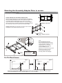
Mounting the Assembly Adapter Plate to screen
Modify the Adapter Plate
Adaptor Modify the Assembled Adapter Plate
Slide the adapter brackets into Assembled adapter plate slightly.
Place the Assembled Adapter Plate on the back of the display with
one Adapter Bracket aligned with a set of vertical mounting
y.
holes.Then,slide the other Adapter Bracket in or out until it aligns
with the second set of vertical mounting holes.The Adapter should
be horizontally centered on the back of the flat panel displa
Back of Screen
Adaptor and hooks
Adapter
Bracket
Adaptor and hooks Use four M6x12 screws and four washers
and tighten it with Phillips Head Screw Driver.
washers
(̛13x̛6x1.2)
M6x12
Screw
Adaptor and hooks
Mounting
Screw
M6&M8
Hole
M5 Hole
Square
spacer
Top of
Display
Note:
Recessed Mounting Holes.
If the mounting holes are recessed
into the back of the display, use the
supplied spacers to pack the
recessed hole. If the mounting
screw is M5&M6,use the
Spacers1.(K.1.)If the mounting screw
is M8,use the Spacers 2.(K.2.)
Ensure that the brackets are
securely fixed to the display.
*For screen with a hole
pattern in a pocket,spacers
go between Assembly
Adapter Plate and screen. Spacers
For Flat Back Screen
fig C.1
SCREEN
SCREEN
fig C.2
SPACER
SCREW
SCREW
OR
EE(adapter plate)
Select the small,medium,large or extra large screws from the baffled .Fastener pack then attach
screen brackets(AA) to screen following figure C.1 or C.2 on page 7.
7 of 8
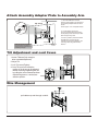
Attach Assembly Adapter Plate to Assembly Arm
1. Insert two M8x15mm screws
and two metal washers into swivel box
on Assembly Adapter Plate as above
shown.
Leave approx. 1/4" of exposed thread.
top screw
Iron spacer
M8x15mm
screw bolt
2. Lift the display and hook it
over the mounting head by lowering
the exposed portion of the top screws
down the open key slots.
.25"
washers
NOTE:This procedure will require
two persons.Ensure that the arm is
set to its maximum negative tilt prior
to attaching the display
M8x15mm
screw
3. Once in position, attach the bottom
two M8x15mm screws and two
washers to secure the display to the
mounting head using M5mm Allen
Wrench.
Tilt Adjustment and cord Coves
WARNING:
Before removing
your
display,ensure
the display has a
negative Tilt and
Tilt Lever is
LOCKED!
1.Loosen Tiltlevers(Only enough to
allow controlled adjustment)
2. Adjust Tilt
3. Lock Tilt Levers(Tighten)
4. Once Tilt Levers are locked,the
position of the levers can be adjusted
without loosening ortightening the unit
by pulling the levers outwards and then
repositioning them to a vertical,less
Tiltlever
obtrusive position.
Tighten
Loosen
Wire Management
pull cables up and through conduit .
8 of 8