1
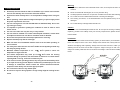
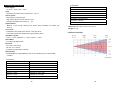
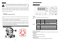
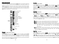
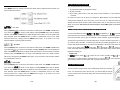
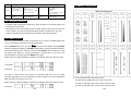
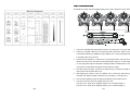
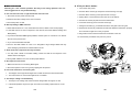
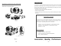
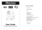
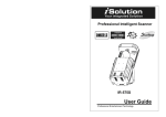
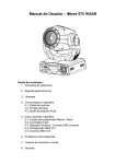
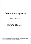
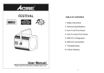
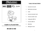
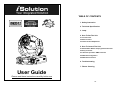
TABLE OF CONTENTS
1. Safety Instruction
2. Technical Specification
3. Lamp
4. How To Set The Unit
4.1 Control Panel
4.2 Main Function
4.3 Home Position Adjustment
5. How To Control The Unit
5.1 Master/Slave Built-In Preprogrammed Function
5.2 Easy Controller
5.3 iSolution Operation / DMX Controller
5.4 DMX 512 Configuration
5.5 DMX 512 Connection
6. Troubleshooting
7. Fixture Cleaning
User Guide
Please read these instructions carefully before use
1E
Warning
To prevent or reduce the risk of electrical shock or fire, do not expose the unit to rain or
1. Safety Instruction
moisture.
Please keep this User Guide for future consultation. If you sell the unit to another
user, be sure that they also receive this instruction booklet.
Unpack and check carefully there is no transportation damage before using the
Never touch bulb with bare fingers, as it is very hot after using.
Hot lamp explosion hazard. Do not open the unit within five minutes after switching off.
Do not start on the unit without bulb enclosure or housing are damaged.
unit.
Before operating, ensure that the voltage and frequency of power supply match
The housing, the lenses, or the ultraviolet filter must be replaced if they are visibly
the power requirements of the unit.
damaged.
The unit is designed for use with the MSD 250/2 or NSD 250/2 lamp. Do not use
Do not look directly at the light while the bulb is on.
any other type of lamp.
It’s important to ground the yellow/green conductor to earth in order to avoid
Caution
electric shock.
There are no user serviceable parts inside the unit. Do not open the housing or attempt any
The unit is for indoor use only. Use only in a dry location.
repairs by yourself. In the unlikely event your unit may require service, please contact your
The unit must be installed in a location with adequate ventilation, at least 50cm
nearest dealer.
from adjacent surfaces. Be sure that no ventilation slots are blocked.
Disconnect main power before fuse/lamp replacement or servicing.
Replace fuse/lamp only with the same type.
Make sure there are no flammable materials close to the unit while operating, as
it is fire hazard.
Use safety chain when fixes this unit. Don’t handle the unit by taking its head only,
Installation
The unit should be mounted via its mounting system ( as shown below ) on the bottom of the
base. Use clamps to fix the unit to truss. Always ensure that the unit is firmly fixed to avoid
vibration and slipping while operating. Always ensure that the structure to which you are
attaching the unit is secure and is able to support a weight of 50 kgs for each unit. Also
but always by taking its base.
Maximum ambient temperature is Ta : 40 ℃ . Don’t operate it where the
always use a safety cable that can hold 10 times of the weight of the unit when installing the
temperature is higher than this.
fixture.
Unit surface temperature may reach up to 85 ℃ . Don’t touch the housing
bare-hand during its operation, and allow about 15 minutes to cool down before
replacing bulb or serving, as the unit could be very hot.
In the event of serious operating problem, stop using the unit immediately. Never
try to repair the unit by yourself. Repairs carried out by unskilled people can lead
to damage or malfunction. Please contact the nearest authorized technical
assistance center. Always use the same type spare parts.
Don’t connect the device to any dimmer pack.
Do not touch any wire during operation as high voltage might be causing electric
shock.
2E
3E
8 Channels:
2. Technical Specification
Channel 1 = Pan
Power supply
- AC 120V ~ 60Hz / 230V ~ 50Hz
Channel 2 = Tilt
Lamp
- Discharge lamp MSD 250/2 or NSD 250/2
Channel 3 = Shutter
GY 9.5
Channel 4 = Effect wheel
Optical system
- High efficiency optical system
Channel 5 = Color
- High quality optical lens and dichroic colors
Channel 7 = Dimmer
- Manually adjustable beam angle: 16°~26°
Channel 8 = CMY Speed
Channel 6 = CYM Color Mix
Shutter/Dimmer
- Blackout, 0~100 smooth dimming and strobe speed variable(1~10 flashes per
second).
Dimension: 428 x 369 x 481 mm (L x W x H)
Weight: 24.2 kg
Color wheel
- Independent color wheel with 6 dichroic colors plus white.
Luminous intensity:
- Color wheel rotates with variable speed, giving rainbow effect.
CMY Mixing system
- Cyan: 0 ~ 100%, Magenta: 0 ~ 100%, Yellow: 0 ~ 100%
Effect Wheel
- Frost filter and diagonal lens
Movement
- Pan: 540° in 2.8 second.
- Tilt: 270° in 1.6 second.
- Automatic pan/ tilt position correction
DMX Channels
- Standard DMX512 signal addressing and can be controlled by any universal DMX
controller.
16 Channels:
Channel 1 = Pan
Channel 9 = Yellow
Channel 2 = Tilt
Channel 10 = CMY color Mix
Channel 3 = Pan/Tilt Speed
Channel 11 = CMY Speed
Channel 4 = Dimmer
Channel 12 = Effect Wheel
Channel 5 = Shutter
Channel 13 = No Function
Channel 6 = Color
Channel 14 = Pan 16 bit
Channel 7 = Cyan
Channel 15 = Tilt 16 bit
Channel 8 = Magenta
Channel 16 = Lamp On/Off/Reset
4E
5E
4. How To Set The Unit
3. Lamp
In case of replacement of the lamp or maintenance, do not open the
4.1. Control Panel
fixture within 15 minutes until the unit cools down after switching off.
Because of its high internal pressure, there might be a risk that the Discharge lamp
would explode during operation. The lamp emits intense UV radiation which is harmful
to the eyes and skin. The high luminance of the arc can cause severe damage to the
retina if looks directly at the lamp.
Discharge lamp:
MSD 250/2 or NSD 250/2 GY 9.5
1. Always switch off the main supply and never handle the lamp or luminaire when it is
Display
To show the various menus and the selected functions
hot.
2. Do not touch the bulb with bare hands. If this happens, clean the lamp with denatured
LED
DMX
On
DMX input present
3. The lamp generates UV radiation. Never operate the lamp without appropriate shielding.
MASTER
On
Master mode
4. When burning, the lamp operates at high pressure and there is a slight risk of arc tube
SLAVE
On
Slave mode
SOUND
Flashing
Sound activation
MENU
To select the programming functions
DOWN
To go backward in the selected functions
UP
To go forward in the selected functions
ENTER
To confirm the selected functions
alcohol and wipe it with a lint free cloth before installation.
rupture. The risk increases with age, temperature and improper handling of the lamp. Do
not use the lamp any longer than its specified life.
Button
5. Make sure the lamp is located in the center of the reflector for the best spot. Adjust lamp
position by screws A, B and C.
Remote controller input
By connecting to the 1/4” microphone jack to control the unit for Stand by, Function, and
Mode function.
Sensitivity
To adjust the sound-receiving sensitivity
Microphone
To receive audio signal for sound activation
DMX input/output
For DMX512 link, use 3-pin XLR plug cable to link the unit together.
6E
7E
4.2. Main Function
Channel Mode
To select any of the pre-set functions, press the MENU button up to when the required one
is shown on the display. Select the function by ENTER button and the display will blink. Use
Press the MENU button up to when the
DOWN and UP button to change the mode. Once the required mode has been selected,
button and the display will blink. Use DOWN and UP button to select the
press the ENTER button to setup or it will automatically return to the main functions without
Channel ) or
any change after idling 8 seconds. To go back to the functions without any change press the
ENTER button to setup or automatically return to the main functions without any change
MENU button. The main functions are shown below:
after 8 seconds. To go back to the functions without any change press the MENU button
is shown on the display. Pressing ENTER
(16
(8 Channel) mode. Once the mode has been selected, press the
again.
DMX512 Address Setting
Setting 16 Channel
Setting 8 Channel
Show mode 1
Show mode 2
Show mode 3
Show mode 4
Slave Mode " Normal "
Slave mode " 2 Light Show "
Blackout Mode " Yes Blackout "
Blackout Mode " No Blackout "
Pan Normal
Pan Inversion
Tilt Normal
Tilt Inversion
MENU
Show Mode
is showing on the display. Pressing ENTER
Press the MENU button up to when the
button and the display will blink. Use DOWN and UP button to select the
or
(show 2) or
(show 3) or
(show 1)
(show 4) mode. Once the mode has
been selected, press the ENTER button to setup or automatically return to the main
functions without any change after 8 seconds. To go back to the functions without any
change press the MENU button again.
Show 1 mode - Fixture is placed on the floor. Tilt movement angle 210°.
LED on
LED off
Show 2 mode - Fixture is fixed under ceiling. Tilt movement angle 90°.
Display Normal
Display Inversion
to the audience’s direction; i.e in front of the stage. Pan movement angle ( left to
Show 3 mode - Fixture is placed on the speaker, The spot is always projecting
Self-Test
right to left ): 160°.
Ambient temperature of lamp
below horizon.)
Fixture Hours
Lamp on
Lamp off
Tilt movement angle:
90° (
60° above horizon; 30°
Show 4 mode - Fixture is fixed under ceiling. The spot is mainly projecting in
front of the stage. Pan movement angle ( left to right to left ) :160°. Tilt movement
angle: 90° ( vertically, front 75°; back 15° )
Reset
Slave Mode
DMX512 Address Setting
Press the MENU button up to when the
is shown on the display. Pressing ENTER
Press the MENU button up to when the
button and the display will blink. Use DOWN and UP button to change the DMX512 address.
is shown on the display. Pressing ENTER
button and the display will blink. Use DOWN and UP button to select the
(normal)
Once the address has been selected, press the ENTER button to setup or automatically
or
(2 light show) mode. Once the mode has been selected, press the ENTER
button to setup or automatically return to the main functions without any change after 8
return to the main functions without any change after 8 seconds. To go back to the functions
seconds. To go back to the functions without any change press the MENU button again.
without any change press the MENU button again.
8E
9E
the MENU button.
Blackout Mode
Display normal mode for the fixture putting on the floor.
button and the display will blink. Use DOWN and UP button to select the
blackout) or
Display inversion mode for the fixture fixing under ceiling.
is shown on the display. Pressing ENTER
Press the MENU button up to when the
(yes
(no blackout) mode. Once the mode has been selected, press the
ENTER button to setup or automatically return to the main functions without any change
after 8 seconds. To go back to the functions without any change press the MENU button
again.
Self-Test
Press the MENU button up to when the
is blinking on the display. Pressing ENTER
button and the unit will run self-test by built-in program. To go back to the functions press the
MENU button again.
Pan Inversion
Press the MENU button up to when the
is shown on the display. Pressing ENTER
button and the display will blink. Use DOWN and UP button to select the
(pan inversion) mode. Once the mode has been selected, press the ENTER
or
Ambient temperature of lamp
(normal)
button to setup or automatically return to the main functions without any change after 8
seconds. To go back to the functions without any change press the MENU button again.
functions press the MENU button again.
Fixture Hours
Tilt Inversion
Press the MENU button up to when the
is shown on the display. Pressing ENTER
button and the display will blink. Use DOWN and UP button to select the
(normal)
(tilt inversion) mode. Once the mode has been selected, press the ENTER
or
is blinking on the display. Pressing ENTER
Press the MENU button up to when the
button and the ambient temperature of lamp will show on the display. To go back to the
Press the MENU button up to when the
is blinking on the display. Pressing ENTER
button and the display will show the number of working hours of the unit. To go back to the
functions press the MENU button again.
button to setup or automatically return to the main functions without any change after 8
Lamp ON/OFF
seconds. To go back to the functions without any change press the MENU button again.
Press the MENU button up to when the
Led Display
is showing on the display. Pressing
Press the MENU button up to when the
ENTER button and the display will blink. Use DOWN and UP button to select the
(Led on) or
is blinking on the display. Pressing ENTER
button and the display will blink. Use DOWN and UP button to select the
(Led off) mode. Once the mode has been selected, press the ENTER
or
(Lamp on)
(Lamp off) mode. Once the mode has been selected, press the ENTER button to
setup or automatically return to the main functions without any change after 8 seconds. To
go back to the functions without any change press the MENU button again.
button to setup or automatically return to the main functions without any change after 8
seconds. To go back to the functions without any change press the MENU button again.
Reset
Press the MENU button up to when the
Display Inversion
It is good for you to install the unit on the floor or under ceiling. Press the MENU button up to
when the
is blinking on the display. Use the ENTER button to change to the mode
(display inversion), It will automatically store after 8 seconds. Or press the ENTER
button again return to the mode
is blinking on the display. Pressing ENTER
button and all channels of the unit will return to their standard position. To go back to the
(display normal). To go back to the functions press
10E
functions press the MENU button again.
DMX RESET :
Set DMX value of channel 8 and channel 16 to 255, then all channels of the unit will return to
their standard home position.
11E
5. How To Control The Unit
4.3 Home Position Adjustment
Press MENU button for at least 5 seconds into offset mode to adjust the home position, the
functions are shown below:
You can operate the unit in three ways:
1. By master/slave built-in preprogram function
2. By easy controller
3. By IL-0824 ( please refer to the user guide of iLead controller ) or by universal DMX
controller
No need to turn the unit off when you change the DMX address, as new DMX address
setting will be effected at once. Every time you turn the unit on, it will show 250U on the
display and move all the motors to their ‘home’ position and you may hear some noises for
about 20 seconds. After that the unit will be ready to receive DMX signal or run the built-in
programs.
Pan offset
Press the MENU button for at least 5 seconds into offset mode, use DOWN and UP button
up to when the
5.1. Master/Slave Built-In Preprogrammed Function
is shown on the display. Pressing ENTER button and the display
will blink. Use DOWN and UP button to adjust the pan home position. Once the position has
been selected, press the ENTER button to setup or automatically return to the offset
functions without any change press the MENU button again, To go back to the main
functions without any change after 8 seconds.
You can select blackout mode
in
(yes blackout) or
(no blackout)
mode while the unit is turned on. By linking the units in master/slave connection, the first unit
will control the other units to give an automatic, sound activated, synchronized light show.
This function is good when you want an instant show. You have to select show (show 1, 2, 3,
4) modes by easy controller . Its DMX input jack will have nothing plugged into it, and Its
master LED will be constantly on and sound LED will flash to the music. The other units will
Tilt offset
Press the MENU button for at least 5 seconds into offset mode, use DOWN and UP button
up to when the
is shown on the display. Pressing ENTER button and the display will
blink. Use DOWN and UP button to adjust the tilt home position. Once the position has been
and select
(normal) or
(2 light show)
have to set in slave mode
mode, Their DMX cables plugged into the DMX input jacks (daisy chain) and the slave LED
lights will constantly on.
2-light show
selected, press the ENTER button to setup or automatically return to the offset functions
without any change press the MENU button again, To go back to the main functions without
In
any change after 8 seconds.
on the second unit to
2-light show. In order to create a great light show, you can set
get contrast movement to each other, even if you have two units only.
(slave mode),
means the unit works normally and
Color offset
Press the MENU button for at least 5 seconds into offset mode, use DOWN and UP button
up to when the
5.2. Easy Controller
is shown on the display. Pressing ENTER button and the display
will blink. Use DOWN and UP button to adjust the color home position. Once the color has
The easy remote control is used only in master/slave mode. By connecting
been selected, press the ENTER button to setup or automatically return to the offset
to the 1/4” microphone jack of the first unit, you will find that the remote
functions without any change press the MENU button again, To go back to the main
control on the first unit will control all the other units for Stand by, Function
functions without any change after 8 seconds.
and Mode.
12E
13E
means
Stand by
Function
Mode
Blackout the unit
Strobe
1. Color sync. strobe
2. Sync. strobe
3. Two-light strobe
X/Y moving show pattern Color selection
selection
( Show 1 ~ Show 4 )
Please refer to 4.2. Main
Functions- Show mode
X/Y moving setting
1.Pan position
2.Tilt position
3.Dimmer
First set Master unit, then set
Slave units’ position
Sound 1
(LED off )
Sound 2
(LED normal blinking)
Position/ Latch
(LED fast blinking)
Slow/Sound 3
(LED on)
5.4. DMX512 Configuration
5.3.1 iSolution Operation
·Consistent DMX configuration enable iScan, iRock and iShow to be linked together and
controlled at the same time.
·DMX address can be set remotely by iLead controller ( please refer to the user manual of
iLead controller ). No need to calculate the DMX channels of each fixture in the chain.
·Automatic switching between DMX function and built-in stand alone programs.
5.3.2 DMX Controller
If you use a universal DMX controller to control the units, you have to set DMX address from
1 to 512 channel so that the units can receive DMX signal.
Press the MENU button up to when the
is shown on the display. Pressing ENTER
button and the display will blink. Use DOWN and UP button to change the DMX512 address.
Once the address has been selected, press and keep ENTER button pressed up to when
the display stops blinking or storing automatically 8 seconds later. To go back to the
functions without any change press the MENU button again.
Please refer to the following diagram to address your DMX512 channel for the first 4 units.
16 Channels:
8 Channels:
You have to set the fixture’s show mode in 8 channels mode when you use IL-0824
controller. DMX address can be set remotely by IL-0824 controller. No need to calculate the
DMX channels of each fixture in the chain.
Please refer to the following diagram to address your DMX512 channel for the first 4 units.
i.) The unit will reset after about five seconds.
For DMX reset, put DMX value of CH-8 & CH-16 to 255,
For lamp on, put DMX value of CH-8 to 247 & CH-16 to 255.
For lamp off, put DMX value of CH-8 to 239 & CH-16 to 255.
8 Channels:
14E
15E
5.5. DMX512 Connection
The DMX512 is widely used in intelligent lighting control, with a maximum of 512 channels.
1.
If you use a controller with 5 pins DMX connector, you need to use a 5 to 3 pin adapter.
2.
At last unit, the DMX cable has to be terminated with a terminator. Solder a 120-ohm
1/4W resistor between pin 2(DMX-) and pin 3(DMX+) into a 3-pin XLR-plug and plug it
in the DMX-output of the last unit.
3.
Connect the unit together in a “daisy chain” by XLR plug from the output of the unit to
the input of the next unit. The cable cannot be branched or split to a “Y” cable. DMX512
is a very high-speed signal. Inadequate or damaged cables, soldered joints or corroded
connectors can easily distort the signal and shut down the system.
4.
The DMX output and input connectors are pass-through to maintain the DMX circuit,
when power is disconnected to the unit.
5.
Each lighting unit needs to have an address set to receive the data sent by the
controller. The address number is between 0-511 (usually 0 & 1 are equal to 1).
6.
The end of the DMX512 system should be terminated to reduce signal errors.
7.
3 pin XLR connectors are more popular than 5 pins XLR.
3 pin XLR: Pin 1: GND, Pin 2: Negative signal (-), Pin 3: Positive signal (+)
5 pin XLR: Pin 1: GND, Pin 2: Negative signal (-), Pin 3: Positive signal (+)
16E
17E
6. Troubleshooting
G. If The pan belt is broken
Following are a few common problems that may occur during operation. Here are
some suggestions for easy troubleshooting:
A. The unit does not work, no light and the fan does not work
1. Turn off the main power.
2. Unscrew all the screws (A) and open the base-housing cover (B).
3. Unscrew all the screws (C) and open the arm cover (D).
1. Check the connect power and main fuse.
4. Unplug all the connect wires that from the arm to the bottom.
2. Measure the mains voltage on the main connector.
5. Unscrew the screws (E) and remove the fixture head.
3. Check the power on LED.
6. Loose the screws (F), then loose the screws (G).
B. Not responding to DMX controller
7. Change a new belt (H) , put the belt around the axis gear and motor gear.
1. DMX LED should be on. If not, check DMX connectors, cables to see if link properly.
2. If the DMX LED is on and no response to the channel, check the address settings and
DMX polarity.
8. Screwed the screws (G), install the new belt and adjust the belt tension properly. Note:
do not fix belt too tight as it is easy to rupture.
9. Plug all the connect wires back that from the bottom to the arm.
3. If you have intermittent DMX signal problems, check the pins on connectors or on PCB of
10. Reverse the procedures from point 5 to point 2.
the unit or the previous one.
4. Try to use another DMX controller.
5. Check in the DMX cables run near or run alongside to high voltage cables that may
cause damage or interference to DMX interface circuit.
C. Some units don’t respond to the easy controller
C
D
C
1. You may have a break in the DMX cabling. Check the LED for the response of the
D
master/ slave mode signal.
2. Wrong DMX address in the unit. Set the proper address.
A
E
F
D. No response to the sound
B
B
A
H
1. Make sure the unit is not receiving DMX signal.
2. Check microphone to see if it is good by tapping the microphone
E. One of the channels is not working well
1. The stepper motor might be damaged or the cable connected to the PCB is broken.
A
G
2. The motor’s drive IC on the PCB might be out of condition.
F. The lamp is cutting out intermittently
1. The lamp is not working well. Check the main voltage either too high or too low.
2. Internal temperature may be too high. Check and if necessary replace the fan on the
head.
18E
19E
7. Fixture Cleaning
Pay attention to the belt tension when install the belt.
The cleaning of internal and external optical lenses and/or mirrors must be carried out
Please refer to the photos below:
periodically to optimize light output. Cleaning frequency depends on the environment in
which the fixture operates: damp, smoky or particularly dirty surrounding can cause greater
accumulation of dirt on the unit’s optics.
Clean with soft cloth using normal glass cleaning fluid.
Always dry the parts carefully.
Clean the external optics at least every 20 days. Clean the internal optics at least every
30/60 days.
F
EC Declaration of Conformity
G
We declare that our products (lighting equipments) comply with the following
Photo 1
specification and bears CE mark in accordance with the provision of the
Electromagnetic Compatibility (EMC) Directive 89/336/EEC.
EN55014-2: 1997 A1:2001, EN61000-4-2: 1995; EN61000-4-3:2002;
EN61000-4-4: 1995; EN61000-4-5: 1995, EN61000-4-6:1996,
EN61000-4-11: 1994.
&
Harmonized Standard
EN60598-1: 2000+ALL:2000+A12:2002
Safety of household and similar electrical appliances
Part 1 : General requirements
Adjust belt tension through loose the screw
Photo 2
20E
Innovation , Quality , Performance
21E