1
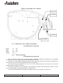
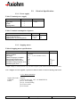
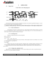
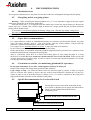
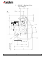
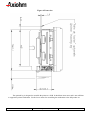
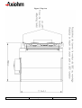
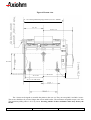
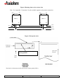
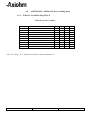
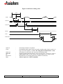
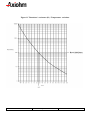
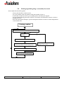
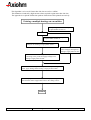
HTPN9050 USER MANUAL Reference : FDE - 3105721 - A November 99 AXIOHM, 1-9 Rue d’Arcueil BP 675, 92542 Montrouge Cedex, France Tel : (33) (0) 1 47 46 78 00 Fax (33) (0) 1 46 55 13 44 1/31 Table of Contents 1. GENERAL .............................................................................................................................. 5 2. SPECIFICATIONS.................................................................................................................. 5 2.1. Mechanical specifications ......................................................................................................................................5 2.1.1. 2.1.2. 2.2. Dimensions of the complete mechanism : .........................................................................................................6 Chassis mounting .............................................................................................................................................6 Electrical Specifications.........................................................................................................................................7 2.2.1. 2.2.2. 2.2.3. 2.2.4. 2.2.5. 2.2.6. Power supply ....................................................................................................................................................7 Stepping motor.................................................................................................................................................7 Microswitch specifications................................................................................................................................8 Opto-sensor specifications ................................................................................................................................8 Recommended use Opto-sensor ........................................................................................................................9 Printhead specifications..................................................................................................................................10 3. OPERATION ........................................................................................................................ 11 3.1. Paper feed.............................................................................................................................................................11 3.1.1. 3.1.2. 3.1.3. Motor initialisation :.......................................................................................................................................11 Printing mode : ..............................................................................................................................................11 Closing door and motor feed :.........................................................................................................................11 4. RECOMMENDATIONS ........................................................................................................ 12 4.1. - Mechanical stress...............................................................................................................................................12 4.2. - Energising and de energising printer................................................................................................................12 4.3. - Paper drive recommendations:..........................................................................................................................12 4.4. - Constraints to consider for maintaining printhead life expectancy : ..............................................................12 4.5. - Specific Recommendation for Version with Latch............................................................................................12 5. APPENDICES ...................................................................................................................... 13 5.1. APPENDIX 1 : Drawings of Printer....................................................................................................................14 5.2. APPENDIX 2 : 64-BIT LSI DRIVERS CHART AND OPERATION................................................................18 5.3. APPENDIX 3 : Electrical specifications of 64-bits LSI driver ...........................................................................20 5.4. APPENDIX 4 : 64 Bits LSI driver timing chart..................................................................................................21 5.4.1. TYPICAL LOADING SEQUENCE................................................................................................................21 5.5. APPENDIX 5 : Thermistor specifications ...........................................................................................................23 5.6. GENERAL CHARACTERISTICS .....................................................................................................................23 5.7. APPENDIX 6 : Heating time for HTPN9050 ......................................................................................................25 5.8. Printing algorithm giving a reasonably fast result..............................................................................................27 5.9. APPENDIX 7 : PAPER SPECIFICATIONS.......................................................................................................29 5.10. APPENDIX 8 : Printer connections.................................................................................................................30 HTPN9050 User's Manual Page 2 / 31 Reference : FDE - 3105721 - A List of figures: General view of printer ...........................................................................................................................................................5 Cut through view of printer .....................................................................................................................................................6 Right view.............................................................................................................................................................................14 Front view.............................................................................................................................................................................15 Top view ...............................................................................................................................................................................16 Bottom view..........................................................................................................................................................................17 Driver chart ..........................................................................................................................................................................18 Routing data to the resistor dots ............................................................................................................................................19 Dots print order.....................................................................................................................................................................19 LSI driver timing chart .........................................................................................................................................................22 Thermistor's resistance (R) / Temperature variations.............................................................................................................24 Pin numbers of flex cable ......................................................................................................................................................31 List of tables: Summary of printer specifications ...........................................................................................................................................4 Nominal power supply ............................................................................................................................................................7 Nominal consumption of printer..............................................................................................................................................7 Stepping motor specifications..................................................................................................................................................7 Motor feed timing diagram....................................................................................................................................................11 General electrical description of drivers ................................................................................................................................20 LSI driver symbols ................................................................................................................................................................21 Pinout of the printer flex cable ..............................................................................................................................................30 Recommended connectors for the flex cable ..........................................................................................................................31 HTPN9050 User's Manual Page 3 / 31 Reference : FDE - 3105721 - A WARNING This manual contains the basic operations to run your printer. Read it carefully before using your printer paying full attention to the chapter recommendations. Table 1 Summary of printer specifications ITEM VALUE UNIT Printing method - Current Consumption : Vcc Static thermal dot line printing 384 8 48 +0.1 60 -0.1 By Thermistor 2 0.125 Opto-sensor 4.75-5.25 4.5-7 1 42 * 55 250 325 5 Storage range Relative humidity Operating range Electrical lifetime *3 -20 to +60 no condensing 0 to +50 108 °C pulses on OE signal Mechanical lifetime *3 Dimensions Width Depth Height Weight Recommended paper 30 km Number of resistor dots Resolution Printing width Paper width Head T° detection Paper feed pitch Paper empty detection Operating voltage range Vcc (logic) Vch (dot) Current Consumption: Vch Current Consumption: Stepping motor dots Dots/mm mm mm Motor steps mm V DC V DC mA per resistor dot "on" at 5V mA per resistor dot "on" at 6.5V mA per activated phase at 5V mA per activated phase at 6.5V mA per 64 resistor dot ‘on’ at 5V °C 92.8 mm 76 mm 55 mm 150 g 2320061 in Axiohm references or other Axiohm approved papers (ex. : Jujo AF KS50 E3 & TF KS 50E3) *1 For a printhead with a resistance of 120 Ω *2 In standard conditions: 5 Volts, 30°C, for a printhead with a resistance of 120 Ω, at 480 PPS *3 Per AXIOHM conditions ( which are mainly : 5 V, room temperature (≈ 25°C), 480 pps, dot printing duty cycle = 30 %) HTPN9050 User's Manual Page 4 / 31 Reference : FDE - 3105721 - A 1. GENERAL Based on static thermal printing technology, the HTP printers are very easy to use, high reliability devices which are designed to be integrated into a large range of hand-held terminals. This manual also described the version HTPN9150, HTPN9450 and HTPN9550. Those references are versions with translucent cover, or/and latched cover. 2. 2.1. SPECIFICATIONS Mechanical specifications Figure 1 General view of printer Cover Molded chassis Tear-off bar Door closed microswitch Stepping motor Printhead spring HTPN9050 User's Manual Drive gear Page 5 / 31 Reference : FDE - 3105721 - A Figure 2 Cut through view of printer Ruber roller Print head Flex cable Out of paper opto sensor 2.1.1. Dimensions of the complete mechanism : (see appendices for drawings) Height Depth Width Weight : 55 mm : 76 mm : 92.8 mm : 150 g 2.1.2. Chassis mounting (see appendices for drawings) The user should be aware of not stressing the printer mechanism. Otherwise print quality can be degraded producing defects such as light printing or non homogeneity of the print. The only screws proposed for mounting are M2,5 or M2,6 only. They should not enter the nuts further than 4 mm in which case nuts could be damaged and turn freely inside bucket. The maximum torque applicable to the screws is 0,2 Nm. Disrespecting this could result in loose inserts inside the bucket (destructive situation). The printer's mechanism is not designed to hold anything more than itself and the paper within. No extra mass or weight should be attached through the assembly screws. It is not recommended to have any other part within close proxiity to the gears or print head. HTPN9050 User's Manual Page 6 / 31 Reference : FDE - 3105721 - A 2.2. Electrical Specifications 2.2.1. Power supply Table 2 Nominal power supply Printer Printhead : Logic (Vcc) Dot line Stepping Motor HTPN9050 5 5 5 V DC Table 3 Nominal consumption of printer Printer Printhead : Heating current / dot (Vch) Logic current/ dot (Vcc) Stepping motor (2 activated phases) * at nominal voltage HTPN9050 42* maxi 0.5 500 Units mA mA mA 2.2.2. Stepping motor Table 4 Stepping motor specifications Recommended control voltage Coil Resistance Number of phases Pitch angle Number of steps per revolution Paper feed for 2 motor steps Recommended control current Maximum starting frequency at 5V Maximum speed (at 5V * ) 5 20 2 (bipolar) 7.5° +/- 1° (non cumulative error) 48 0.125 250 620 680 VDC Ω +/- 7% mm mA/phase step/s step/s * higher voltage (or current) allows to go a bit faster (higher speed indicated in the heating time table). Note : if higher current is applied, a special care must be taken to avoid overheating of the motor 2.2.2.1. Motor connection length of the leads : 100 mm Connector : 6 pins top entry type J.S.T ref. B6B-PH-K-S Pinout : pin 1,2 : first winding pin 3,4 : second winding pin 5: Door switch pin 6: Ground HTPN9050 User's Manual Page 7 / 31 Reference : FDE - 3105721 - A 2.2.3. Microswitch specifications Contact resistance Maximum rating :<1Ω : 0.1 A -30 V DC 2.2.3.1. Connection Leads length Connector Switch Switch : 120 mm : Together with motor Door open closed 2.2.4. Opto-sensor specifications Absolute Maximum ratings IF (mA) 50 VR (V) 5 PD(mW) 75 VCEO(V) 30 IC(mA) 20 PC(mW) 75 VF (V) IF = 4 mA IR (µA) VR = 5 V ICEO (A) VCEO = 10V VCE(sat)(v) - Maxi 1.2 Maxi 10 Maxi 1.10-7 IO (mA) VCE = 5 V IF = 4 mA Typical 100 tr (µs) IC = 0.1 mA RL = 1 kΩ Typical 30 - 2.2.4.1. Connection Integrated with the printhead connection (See appendices) HTPN9050 User's Manual Page 8 / 31 Reference : FDE - 3105721 - A 2.2.5. Recommended use Opto-sensor The user should be aware that opto-sensors characteristics have very wide tolerances. We thus recommend the use of one of the schematics below. 2.2.5.1. Opto Sensor : Sample minimal external circuit VCC(5V) 47KΩ PRINTER Vo OPTO-SENSOR If Condition: For If = 20 mA ......... Output signal is LOW when paper is PRESENT ......... Output signal is HIGH when paper is EXHAUSTED Vo<1V, Vo>4V. 2.2.5.2. Sample external circuit with low consumption VCC(5V) VCC(5V) 10KΩ PRINTER OPTO--SENSOR µp output port BC807 47KΩ Vo 178Ω If Condition: Pulse wave from output port with low level during 0.6 ms, measuring Vo 0.2 ms after pulse falling edge. Same conditions for output signal Vo as in 2.2.5.1. HTPN9050 User's Manual Page 9 / 31 Reference : FDE - 3105721 - A 2.2.6. Printhead specifications Printer HTPN9050 Driver chips * 6 - Operating range (Vcc) / LSI supply Mean dot resistance (+ 10%) 4.75-5.25 * V DC 120 Ω Nominal dot supply voltage (-10/+40%) 5 V DC Nominal Heating current per dot 42 mA Filter any transient signal and parasitic on this line. Separate Vcc from Vch because Vch can go lower than 4.75 Volts. Vcc must be connected to the same power supply than the other electronic circuits which drive the printer. Note that three rank of head resistance are defined depending on the head resistance. This rank is indicated on the head (either on a sticker or directly written on the head). It allows to adjust heating time if very precise driving is required. Ranks are depicted in the table here after : Head resistance 127 to 132 Ω 115 to 126 Ω 108 to 114 Ω HTPN9050 User's Manual Rank A B C Page 10 / 31 Reference : FDE - 3105721 - A 3. 3.1. OPERATION Paper feed Table 5 Motor feed timing diagram t1 IP1 t2 IP2 Motor Steps td Heating cycles Note that each time the motor has been stopped for more than 8 ms, the next step should be longer by 1 ms in order to restart the motor in the appropriate position. Heating of subline should be started after a time td>0.5ms in order to reduce risks of unevenly spaced sublines when overheating the paper. Td can be reduced to 0 if the heating time is well adapted to the paper used. 3.1.1. Motor initialisation : This operation is necessary to place the motor in a good position when the printer electronic is powered on or reseted. Both phases must be powered with the same current during t1=1 ms. It must be followed by 16 motor steps in order to compensate the play in the gears. 3.1.2. Printing mode : There are 4 different positions for the motor phases. If P1 = A ; P2 = B The circulation is : __ ____ __ AB ⇒ AB ⇒ AB ⇒ AB ⇒ AB The position of the phases must be kept in memory while the phase currents are switched to zero in order to restart the motor in a good position. IP = ± 250 mA t2 > 2.2 ms After the motor has been switch off, before feeding the paper for further printing, the phases must be repowered at their position before switch off during 5 ms. Otherwise unevenly spaced lines may be printed. During printing, the motor phases should be maintained otherwise a paper motion can occur and induce unevenly spaced sublines. 3.1.3. Closing door and motor feed : When the door is closed, you should feed 1 to 2 cm of paper at high speed in order to reposition the platen roller and cover in good mechanical conditions. HTPN9050 User's Manual Page 11 / 31 Reference : FDE - 3105721 - A 4. 4.1. RECOMMENDATIONS - Mechanical stress Never apply mechanical stress to the printer because this could cause misalignment and degrade print quality. 4.2. - Energising and de energising printer Warning ! : When energising the thermal printhead (Vcc, 5 V) it is important to apply all the logic signals within 4 ms (particularly to de-energise all the OEs). If the line of dots (Vch, 5 V) is supplied before the control logic, resistor dots may be destroyed. Because the control logic has a random state, resistors might be heated for a longer period than the specified maximum, burning out the heated resistor. To avoid this, we recommend applying the heating voltage (Vch, ) after the logic supply voltage (Vcc). The same precaution should be taken at shut down. The heating supply Vch must be switched off before the logic supply Vcc. Care should be taken to allow enough time for residual capacitive charge to dissipate. 4.3. - Paper drive recommendations: - Use a paper reference 2320061 in AXIOHM classification (or references specified in this manual). Any other paper can induce problems such as : poor print quality, unevenly spaced sublines, reduced head life expectancy, chemical incompatibilities with bucket, roller or head. - Use a paper roll of a maximum diameter of 50 mm. A paper jam could occur otherwise. - Do not run the printer without paper: this would damage the printer. - Ensure that adequate air circulation around the printhead support/heatsink is provided. Poor ventilation of the printhead support/heatsink can degrade the print quality. - There is a possibility (when there is no latch) after loading paper (or after puling the paper in a wrong direction to cut it) that the cover switch stays open because the cover is not well closed. In this case the end of paper optical sensor will detect paper, try once to achieve 16 motor steps and check again the cover switch, if it stays open then stop printing. 4.4. - Constraints to consider for maintaining printhead life expectancy : - Do not print if thermistor is over 60°C. If this happens, head may be destroyed. - Respect other voltages and timings limits specified in this document. - Logic voltage on chip : care should be taken to filter any transient signal or parasitic in order to keep the driver in a known state: failure to observe this may result in head destruction. Separate the Vch and Vcc signals in order to stay in the defined limits of voltage on Vcc. Vcc must be connected to the same power supply than the other electronic circuits which drive the printer. 4.5. - Specific Recommendation for Version with Latch Enough Space must be left in front of the latch (on the host system) so that the user can release the latch with his finger (versions HTPN9450 and HTPN9550). See drawing "left" The latch should not be released from the side The latch must be released from the front HTPN9050 User's Manual Page 12 / 31 Reference : FDE - 3105721 - A 5. HTPN9050 User's Manual APPENDICES Page 13 / 31 Reference : FDE - 3105721 - A 5.1. APPENDIX 1 : Drawings of Printer Figure 3 Right view 10.3 ± 0.1 12.25 ± 0.1 24.5 ± 0.2 HTPN9050 User's Manual Page 14 / 31 Reference : FDE - 3105721 - A Figure 4 Front view The optional leg is designed to assemble the printer to a PCB. It should not incur stress and is not sufficient to support the printer mechanism. Use the lower inserts for assembling the mechanism to the full product set. HTPN9050 User's Manual Page 15 / 31 Reference : FDE - 3105721 - A Figure 5 Top view HTPN9050 User's Manual Page 16 / 31 Reference : FDE - 3105721 - A Figure 6 Bottom view 71 ± 0.2 when printhead spring is fitted (71.5± 0.1 without) 53.9 ± 0.5 45 ± 0.2 32.5 ± 0.1 40.4 ± 0.1 36.5 ± 0.5 with cover The 3 inserts are designed to assemble the printer to the user set. They can accept M2.5 and M2.6 screws. The screws should not be screwed longer than 4 mm inside bucket. The maximum acceptable torque is 0.2 Nm. The maximum pulling effort is 50 N by insert. Screwing outside of these maximum values may destroy the bucket. HTPN9050 User's Manual Page 17 / 31 Reference : FDE - 3105721 - A 5.2. APPENDIX 2 : 64-BIT LSI DRIVERS CHART AND OPERATION The LSI power and multiplexing circuit drivers located on the thermal printhead provide power control from logic signals and the DC power supply voltage. These circuits are supplied by 5 V ± 5% logic voltage. Take care to filter transient and parasitic on all logic lines. Undetermined states can happen and destroy the head. The power source should be disconnected from the logic source. The logic source must be connected to the same source as the electronic circuits in charge of controlling the printer. Each circuit features 64 open collector transistors, a 64-bit shift register and a 64-bit memory register. Each circuit controls 64 resistor dots on the printhead. Figure 7 Driver chart Vch 1 2 3 4 ...... (OUTPUTS).... 62 63 64 Line of resistor dots GND Output Enable (OE) OE Strobe 64 bits buffer register Serial Input (SI) 64 bits shift register CLOCK SERIAL OUTPUT (SO) HTPN9050 User's Manual Page 18 / 31 Reference : FDE - 3105721 - A Figure 8 Routing data to the resistor dots Note : See Appendix "Connection" for the available signals on the printer connection. R64 R1 R64 R1 Resistors Resistors CHIP n CHIP n+1 SI SO SI SO OUT IN CLK Strobe OE n OE n+1 Figure 9 Dots print order see on next page for description of dots position. paper path direction The first bit of data entered will be the first bit of data printed (FIFO). HTPN9050 User's Manual Page 19 / 31 Reference : FDE - 3105721 - A 5.3. APPENDIX 3 : Electrical specifications of 64-bits LSI driver Table 6 General electrical description of drivers Description Max. voltage at outputs 1 to 64 Max. voltage any other pin Max. output current Total max. output current Min Maxi 7 5.25 - 45 -2.88 =(64×(- 45.10-3)) Unit Volt Volt mA A The specifications given below are given for the following conditions : Logic voltage on chip : 4.75V < Vdd < 5.25V (care should be taken to filter any transient signal or parasitic in order to keep the driver in a known state: failure to observe this may result in head destruction) Clock frequency : 5 MHz Table 7 Logic current (5 V) Vdd supply current Min. high-level input voltage Max. low-level input voltage Max. high-level input current Max. low-level input current Min. high-level output voltage Max. low-level output voltage CONDITIONS 64 drivers on + VALUES 30 mA SYMBOL Idd Vcc = 5 Volts Vcc = 5 Volts 3.5 V (0.7×Vdd) 1.5 V (0.3×Vdd) 0.5 µA - 0.5 µA 4.45 V 0.05 V Vih Vil Iih Iil Voh Vol Io = Iohmax Io = Iolmax Table 8 Heating Current Max. power output current Max. output leakage current Max. output voltage HTPN9050 User's Manual CONDITIONS Vdon = Vdonmax Vdon = 5V Idout = Idomax VALUES -45 mA 1 µA 1.1 V Page 20 / 31 SYMBOL Idomax Idoleak Vdonmax Reference : FDE - 3105721 - A 5.4. APPENDIX 4 : 64 Bits LSI driver timing chart 5.4.1. TYPICAL LOADING SEQUENCE Table 9 LSI driver symbols Symbol Tclk t2 t3 t4 t5 t6 t7 t8 t9 t10 Description serial clock period clock pulse width data in to clock set-up time data in from clock hold time strobe high time clock to strobe delay time serial data out from clock delay OE to data out delay time data out fall time 10% --> 90% data out rise time 10% --> 90% Min Typ Maxi 5 70 40 40 100 100 1.5 1.5 120 4.5 4.5 4.5 Unit Mhz ns ns ns ns ns ns µs µs µs Vdd = 5V, Temp = 25 °C with resistive load, R1=120Ω connected to 5V HTPN9050 User's Manual Page 21 / 31 Reference : FDE - 3105721 - A Figure 10 LSI driver timing chart Tclk t2 Clock t3 t4 Serial in t7 t7 Serial out t6 t5 Strobe OEn: t8 t9 t8 t10 Data Out n : 90% 10% Serial in Clock : : Serial out STROBE OE Data Out n Note : : : : : HTPN9050 User's Manual 90% 10% Serial input for data to be printed Serial/parallel shift register clock, activated on leading edge of pulse (rest level = logic 0) Clock frequency is 5 MHz. The rising time of clock must be < 50 ns Serial data out sent back to the connector of the thermal head Signal for putting data into memory, active on logic level 1 (rest level = logic 0) Output Enable (OE1 to OE3): power activation signals active at logic level 1. Internal data out to heating points (not available on connector) All these inputs are CMOS compatible. Page 22 / 31 Reference : FDE - 3105721 - A 5.5. APPENDIX 5 : Thermistor specifications This thermistor has a resistance variation can be expressed as follows : Equation 1 Resistance value of thermistor 1 1 B× − T Tn R = Rn × e where T is in Kelvin degrees (°K) B = 4066 °K Rn = 100 KΩ : reference value at temperature Tn (298°K) The main specifications of the thermistor are listed in the following pages. NTC thermistor, rectangular size (IEC 12.05), silver palladium metallic coating. 5.6. GENERAL CHARACTERISTICS * Climatic category (IEC) 40/85/56 * Maximum operating temperatures : -20°C to +80°C * Rated resistance at 25° C : Rn = 100 KΩ (see table of values) * Tolerance for Rn : 5% * Maximum dissipation at 25° C : Pmax = 0.24 mW * Thermal dissipation factor : 5 mW/°C * Thermistor time constant / dot line : t = 30 sec * Resistance value as a function of temperature (see curves) Note that printing should be stopped if the thermistor value goes over 60°C. HTPN9050 User's Manual Page 23 / 31 Reference : FDE - 3105721 - A Figure 11 Thermistor's resistance (R) / Temperature variations HTPN9050 User's Manual Page 24 / 31 Reference : FDE - 3105721 - A 5.7. APPENDIX 6 : Heating time for HTPN9050 The heating time table is presented on next pages, it was achieved with the JUJO TF50KS E3 paper The motor cycle time for one dot line is given in the second top line of the table, it is the time for two motor steps. The column 3 (indicated with : speed <2 mm/s and motor cycle time > 62.5 ms) gives the required heating time, giving the necessary energy to obtain an optical density of 1.2. Three areas are then defined in the table : Area 1 : "white" : the motor cycle time for one dot line is greater than the heating time indicated in column 3 Area 2 : high lighted : the maximum heating time is greater than the motor cycle time Area 3 : indicated by " * " : the required heating time (function of speed, voltage and temperature) becomes greater than the motor cycle time, printer cannot be operated. How to use tables ? heating time can be controlled either with or without historical control. - Without historical control : apply the indicated heating time given as a function of speed, voltage and temperature. At high speed, printing quality for isolated dots might be affected with this method. Example : at 25 mm/s, 25°C and 5 volts : 3.85 ms - With historical control in area 1 : apply the indicated heating time (function of speed, voltage and temperature) when the dot has been heated on the previous subline, and the time from column 3 when it has not. This method gives the best printing quality. Example : at 25 mm/s, 30°C and 6 volts : previous dot dot to heat Heating time to apply dot ON 2.39 ms dot OFF 4.28 ms - With historical control in area 2 : apply the indicated heating time (function of speed, voltage and temperature) when the dot has been heated on the previous subline, and the motor cycle time when it has not. At high speed, printing quality for isolated dots might be slightly affected with this method. Example: at 35 mm/s, 10°C and 6.5 volts : previous dot dot to heat Heating time to apply dot ON 2.21 ms dot OFF 3.57 ms HTPN9050 User's Manual Page 25 / 31 Reference : FDE - 3105721 - A Speed (mm/s) Voltage Temp °C 4 Volts 4 Volts 4 Volts 4 Volts 4 Volts 4 Volts 4,5 Volts 4,5 Volts 4,5 Volts 4,5 Volts 4,5 Volts 4,5 Volts 5 Volts 5 Volts 5 Volts 5 Volts 5 Volts 5 Volts 5 Volts 5,5 Volts 5,5 Volts 5,5 Volts 5,5 Volts 5,5 Volts 5,5 Volts 5,5 Volts 6 Volts 6 Volts 6 Volts 6 Volts 6 Volts 6 Volts 6,5 Volts 6,5 Volts 6,5 Volts 6,5 Volts 6,5 Volts 6,5 Volts 6,5 Volts 7 Volts 7 Volts 7 Volts 7 Volts 7 Volts 7 Volts 0 °C 10 °C 20 °C 30 °C 40 °C 50 °C 0 °C 10 °C 20 °C 30 °C 40 °C 50 °C 0 °C 10 °C 20 °C 25 °C 30 °C 40 °C 50 °C 0 °C 10 °C 20 °C 25 °C 30 °C 40 °C 50 °C 0 °C 10 °C 20 °C 30 °C 40 °C 50 °C 0 °C 10 °C 20 °C 25 °C 30 °C 40 °C 50 °C 0 °C 10 °C 20 °C 30 °C 40 °C 50 °C R=120 Ohm < 2 mm/s 10 mm/s 20 mm/s 25 mm/s 30 mm/s 35 mm/s 40 mm/s 50 mm/s 60 mm/s >62,5 ms 12,5 ms 6,25 ms 5 ms 4,17 ms 3,57 ms 3,13 ms 2,5 ms 2,08 ms * * * * * * * * * * 3,87 3,34 * * 3,84 3,63 3,43 3,02 2,61 3,74 3,41 3,08 2,91 2,75 2,42 2,09 3,06 2,79 2,52 2,25 1,98 1,71 2,56 2,33 2,11 1,99 1,88 1,66 1,43 2,16 1,97 1,78 1,59 1,4 1,21 * * * * * * * * * * * 3,17 * * * 3,45 3,25 2,86 2,47 3,54 3,23 2,92 2,76 2,61 2,3 1,98 2,9 2,64 2,39 2,14 1,88 1,63 2,42 2,21 2 1,89 1,78 1,57 1,36 2,05 1,87 1,69 1,51 1,33 1,15 * * * * * * * * * * * 3,02 * * * * 3,1 2,73 2,36 * 3,08 2,78 2,64 2,49 2,19 1,89 2,77 2,53 2,28 2,04 1,79 1,55 2,31 2,11 1,9 1,8 1,7 1,5 1,29 1,96 1,79 1,61 1,44 1,27 1,1 15,06 13,73 12,41 11,08 9,76 8,43 11,34 10,34 9,35 8,35 7,35 6,35 8,85 8,07 7,29 6,9 6,51 5,73 4,96 7,1 6,47 5,85 5,54 5,22 4,6 3,97 5,82 5,3 4,79 4,28 3,77 3,26 4,85 4,43 4 3,79 3,57 3,15 2,72 4,11 3,75 3,39 3,03 2,67 2,3 HTPN9050 User's Manual 10,82 9,87 8,92 7,96 7,01 6,06 8,15 7,43 6,71 6 5,28 4,56 6,36 5,8 5,24 4,96 4,68 4,12 3,56 5,1 4,65 4,2 3,98 3,75 3,3 2,85 4,18 3,81 3,44 3,08 2,71 2,34 3,49 3,18 2,87 2,72 2,57 2,26 1,95 2,95 2,69 2,43 2,17 1,91 1,65 * * * * 5,83 5,04 * 6,18 5,58 4,99 4,39 3,79 5,28 4,82 4,35 4,12 3,89 3,42 2,96 4,24 3,86 3,49 3,31 3,12 2,75 2,37 3,47 3,17 2,86 2,56 2,25 1,95 2,9 2,64 2,39 2,26 2,13 1,88 1,62 2,46 2,24 2,02 1,81 1,59 1,38 * * * * * 4,71 * * * 4,66 4,1 3,54 4,94 4,5 4,07 3,85 3,63 3,2 2,77 3,96 3,61 3,26 3,09 2,91 2,57 2,22 3,25 2,96 2,67 2,39 2,1 1,82 2,71 2,47 2,23 2,11 1,99 1,76 1,52 2,3 2,09 1,89 1,69 1,49 1,29 Page 26 / 31 * * * * * * * * * * * * * * * * * 2,5 2,16 * * * 2,42 2,28 2,01 1,74 * 2,32 2,09 1,87 1,65 1,42 2,12 1,93 1,75 1,65 1,56 1,37 1,19 1,8 1,64 1,48 1,32 1,16 1,01 * * * * * * * * * * * * * * * * * * * * * * * * 1,86 1,61 * * 1,94 1,73 1,53 1,32 1,96 1,79 1,62 1,53 1,45 1,27 1,1 1,66 1,52 1,37 1,22 1,08 0,93 Reference : FDE - 3105721 - A 5.8. Printing algorithm giving a reasonably fast result Some simple rules should be applied: + always print less than 128 dots at once + on a given subline, print only packets of the same number of dots on + if more than 128 dots are on on a given subline print it with the motor stopped + use precomputed heating time tables with the Vch measures and Thermistor measure as index to heating time value. + Drive the motor phases through a specific interruption and timer in order to warrant independence with all other tasks. Printing a subline Count the number N of dots on to be printed on the subline If N>128 then otherwise Yes No send all of them to the printer (see appendix ) Start the motors phases. They should be monitored in parallel with the heating of the dots Call the algorithm for a ’ multiple heatings on one subline ‘ Apply the timings from ‘Heating a packet of dots’ Wait for the end of the motor phases. HTPN9050 User's Manual Page 27 / 31 Reference : FDE - 3105721 - A This algorithm is to be used if more than 128 dots are on for a subline. This limitation is induced by high currents values required to print more than 128 dots. The approach is to split the subline into packets of dots that will be printed successively. Printing a multiple heatings on one subline Yes : printing will be done in 2 packets of equal number of dots on. 129 ≤ N <255 ? No : printing will be done in 3 packets of equal number of dots on. Send the first N/3 dots on to the printer and apply timings from ‘heating a single packet of dots’ Send the first N/2 dots on to the printer and apply timing from ‘heating a single packet of dots’ Send the second N/3 dots on, preceded by dots off for positioning, to the printer and apply timings from ‘heating a single packet of dots’ Send the rest of dots on, preceded by dots off for positioning, to the printer, apply timings from ‘heating a single packet of dots’. Feed in the paper for one subline (2 motor steps). Printing will be done with the motor stopped and return to the calling routine. Return HTPN9050 User's Manual Page 28 / 31 Reference : FDE - 3105721 - A 5.9. APPENDIX 7 : PAPER SPECIFICATIONS The two recommended and tested references for paper are : - JUJO : AF KS50E3 & TF 50KS E3 (used to generate the heating time table shown in this manual) Property Grammage Thickness Surface smoothness Brightness Unit g/m2 µm sec % Value 58.5 ± 2 62 ± 2 500 ± 50 85 min °C 70 OD = 1 °C 78 SCAN P16 SCAN P11 SCAN P4 KN/m mN % 3.2 min 260 min Black 6 ± 0.5 Property Heat resistance Conditions 60°C, 24 hrs Unit OD Humidity resistance 40°C 90%RH 24 hrs (0.49 mj-dot) SCAN P11 25°C, 65%RH, dark place. OD OD OD - Value 0.25 max 1.25 min 0.15 max 1.25 min 0.95 ± 0.05 1.35 ± 0.05 3 years Method ISO 536 ISO 534 ISO 5627 ISO 2470 ISO 1924 OD = 0.2 Unit g/m2 µm sec % KN/m °C Value 58 ± 5 60 ± 5 250 min. 75 min 3.3 min 50 OD = 1 °C 98 ISO 1974 ISO 287 mN % 250 min Black 6.5 ± 1 Static initial activation temperature Static activation temperature Tensile strength Tear Strength Image Colour Moisture stability Dynamic Sensitivity Maximum Density Warranty (Image & Printability) - Method SCAN P6 SCAN P7 SCAN P3 (ISO 2470) OD = 0.2 Kanzaki : KP440 Property Grammage Thickness Surface smoothness Brightness Tensile strength Static initial activation temperature Static activation temperature Tear Strength Image Colour Moisture stability HTPN9050 User's Manual Page 29 / 31 Reference : FDE - 3105721 - A 5.10. APPENDIX 8 : Printer connections Table 10 Pinout of the printer flex cable Pin Number 1 2 3 4 5 6 7 8 9 10 11 12 13 14 15 16 17 18 19 20 21 22 23 24 25 26 Signal Vch Vch CLOCK STROBE D-in GND OE1 OE2 GND GND OE3 GND TH1 TH2 OE4 GND OE5 Collector opto Opto GND Anode opto GND OE6 D-out Vcc Vch Vch Comment Clock signal for serialising data to line Strobe signal for line print Data input GND OE for driver 1 OE for driver 2 GND GND OE for driver 3 GND connected to radiator (heatsink) Thermistor Thermistor OE for driver 4 GND OE for driver 5 Collector of end of paper opto sensor GND for Opto-sensor Anode of end of paper opto sensor GND OE for driver 6 Data out Logic power supply +5V Contact side 26 HTPN9050 User's Manual 1 Page 30 / 31 Reference : FDE - 3105721 - A Figure 12 Pin numbers of flex cable Pin n°26 Pin n°1 Table 11 Recommended connectors for the flex cable N° Supplier Reference 1 Molex 2 Stocko 5597 39-51-3264 5597 30-51-7263 MZF 9386-6-0-2626 MZF 8896-6-0-2626 The Connector requested : 26 pins, step of 1,25 mm, Zero insertion force. Note that using any other connector can destroy the flex cable. HTPN9050 User's Manual Page 31 / 31 Reference : FDE - 3105721 - A